

Abstract
Purpose:
The performance ability of position logic circuitry of gamma-camera to superimpose the X–Y gains obtained from different pulse height analyzers is multiple window spatial registration (MWSR). This study was conducted to evaluate the feasibility of dual-tracer method using 99mTc and 131I to assess MWSR.
Materials and Methods:
The procedure was carried out on a dual-head gamma-camera with rectangular NaI (Tl) crystal using a point source containing 99mTc pertechnetate and 131I-NaI. Pixel coordinates, full width at half-maximum of point spread function at 364 keV and 140 keV, and pixels with maximum count of images for dual detectors were analyzed and compared.
Results:
The experiment demonstrated an excellent correlation between the X and Y coordinates identified on 364 keV and 140 keV images (Spearman’s coefficient of rank correlation: 0.9, P < 0.0001). Intraclass correlation of studies performed on two separate occasions showed a good correlation (k = 0.87) demonstrating the reproducibility of the procedure.
Conclusion:
Dual-tracer method for evaluation of MWSR is a reproducible, accurate, and logical alternative to the routine National Electrical Manufacturers Association procedure.
Keywords: Acceptance tests, gamma-camera, multiple window spatial registration
Introduction
Acceptance tests are a set of tests performed to verify if the performance of installed imaging equipment matches the factory specifications. The reference for such tests, protocols, results, and implications are traceable to the National Electrical Manufacturers Association/International Electrotechnical Commission (NEMA/IEC) publications.[1,2] Standard procedures are performed with necessary phantoms and software, simulating clinical setting, and the results are verified. Some of the tests are so essential that it should be repeated on a routine/periodic basis. The results of acceptance tests form the baseline reference data for the user, which can be referred to during the life of the installed instrument.
There are a few tests that verify individual component of the instrument. One such test that verifies the ability of position logic circuitry to superimpose the X–Y gains obtained from different pulse height analyzers is “multiple window spatial registration” (MWSR). The accuracy of this registration has an implication on the ability of gamma-camera to perform qualitative and quantitative dual-isotope imaging. Few examples include dual-isotope parathyroid imaging with 99mTc sestamibi and 123I-NaI and lung ventilation-perfusion imaging with 133Xe gas and 99mTc MAA.
MWSR is performed using tracers having multiple gamma emissions such as 67Ga, 201Tl, and 111In. However, during pandemic situation, it is mammoth of a challenge to start a new conventional nuclear medicine facility. Given the greater challenges toward the import of radionuclides, custom clearances, and a single vendor for these tracers in the entire geographical area, the cost of 67Ga, 201Tl, and 111In has surged up several times compared to 2015.
As such, MWSR is an optional test for the modern-day gamma-camera which is equipped with 3 and more energy windows for imaging. Relying on these tracers to perform MWSR would not only add additional cost to the “User” but also substantially delay the process of licensing. We present the alternate logical solution for performing MWSR in this article.
Materials and Methods
The procedure was carried out on a dual-head gamma-camera with rectangular NaI(Tl) crystal with a thickness of 3/8th of an inch, 59 photomultiplier tubes in each detector, and a field of view of 533 mm × 387 mm. The procedure was repeated on the following day to assess accuracy and reliability.
Procedure
A point source with a cocktail of 50µCi of 99mTc pertechnetate and 50µCi of 131I-NaI was prepared. The objective was to make sure that the count rate didn’t exceed 10kilocounts/sec when the source is placed close to the exposed face of crystal. The possible reason is to avoid pile-up-related counting losses and image distortion
Adequate safety precautions and personal care were taken at the time of point source preparation
Collimators were removed from the detectors of gamma-camera
Point source was secured tightly in a tungsten-shielded container of thickness 1 cm and a central aperture of approximately 3 mm. It was covered with a tungsten cap of length and width 2.5 cm, respectively [Picture 1]
The detector was covered with a plastic case [Picture 2]. The collimated point source with aperture facing the detector surface was placed over the slots in the plastic case
The photo peaks of 140 keV from 99mTc and 364 keV from 131I were verified
Image acquisition was scheduled for 100 kcts in 256 × 256 matrix and word mode under the two photo peaks separately
Images were acquired by placing the point source approximately at about 75% distance from center to edge of the detector in all 4 quadrants (+X, -X, +Y and –Y) of both detectors.
Picture 1.

Tungsten shield used for securing point source
Picture 2.

Plastic case placed over the uncollimated detector
Image processing and interpretation
Images acquired under the photo peaks of dual energies were subtracted to qualitatively verify the shift in spatial registration of the image
Profiles were drawn along X and Y axes along the entire length and breadth of detector, assuring that it traverses through the center of the hot spot
Full width at half maximum (FWHM) of point spread function of images of both energies was observed and documented for X and Y profiles [represented by pixel number “X” in Pictures 3-6]. The spatial localization of pixel with maximum count for 140 keV and 364 keV was observed. The procedure was performed on both detectors, and the results were documented.
67Ga in its EC, γ mode of decay (T½ 78.26 hours) emits multiple gamma energies like 93keV (39% abundance), 185keV (21% abundance), 296kev (17% abundance), 393keV and 887keV. The NEMA procedure recommends considering 93keV, 185keV and 296keV energies for performing MWSR, as these energies are clinically relevant for imaging. 131I also emits multiple gamma emissions like 364keV (82% abundance), 637keV (7% abundance), 284keV (6% abundance), 723keV (2% abundance), 80keV (3% abundance) and a few more. In the present study, the clinically relevant emissions of 99mTc and 131I were chosen for imaging. There can be contribution of down scatter from higher energies in uncollimated source (5). It is minimal/negligible when the point source is collimated, as described above in the procedure. However, the procedure allows to test if the deviation is significant despite such down scatter contributions.•
Picture 3.

Point spread function of 140 keV image and pixel with maximum count in X coordinate represented by X = 128
Picture 6.

Point spread function of 364 keV image and pixel with maximum count in Y coordinate represented by X = 160
Picture 4.

Point spread function of 364 keV image and pixel with maximum count in X coordinate represented by X = 128
Picture 5.
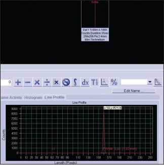
Point spread function of 140 keV image and pixel with maximum count in Y coordinate represented by X = 160
Statistical analysis
Statistical analysis was performed on MedCalc 20.014 software (MedCalc Software bv, Ostend, Belgium; https://www.medcalc.org; 2020). Microsoft Word and Excel were used to generate graphs and tables. Descriptive analysis was performed in this study. Continuous measurements were expressed as mean ± standard deviation (SD). Paired samples t-test was performed to compare FWHM of two images acquired under separate energy windows. Rank correlation was performed to assess pixel match for paired data. Intraclass correlation coefficient was performed to assess consistency / reproducibility of the measurements [Correlation coefficient Kappa <0.5 as poor, 0.5 to 0.75 as moderate, 0.75 to 0.9 as good and values > 0.9 as excellent, were considered].[3]
Results
FWHM of point spread function acquired in 364 keV and 140 keV and pixels with maximum count of images for detectors 1 and 2 were tabulated. The test was repeated on another day, and the results were tabulated.
On day 1
Correlation of the pixel numbers between the two images showed Spearman’s coefficient of rank correlation (rho): 0.963 (confidence interval [CI]: 0.893–0.987, P < 0.0001) and Kendall’s tau: 0.929 [CI: 0.772–0.980, P < 0.0001; Graph 1]. Full width at half maximum (FWHM) of Point spread function (PSF) obtained from 364 keV window in detector 1: 7.4 ± 0.14 (mean ± SD) and in detector 2: 7.21 ± 0.24 (Mean ± SD). Full width at half maximum (FWHM) of Point spread function (PSF) obtained from 140keV window in detector 1: 6.64 ± 0.14 (Mean ± SD) and in detector 2: 6.61 ± 0.20 (Mean ± SD). Paired samples t-test showed a mean difference in FWHM of − 0.6763, t = −13.537, P < 0.0001 [Graph 2].
Graph 1.

Comparison of pixel location of images from 364 keV and 140 keV energy windows in the first study
Graph 2.

Full width at half-maximum of PSF from 364 keV and 140 keV energy windows in the first study
On day 2
Correlation of the pixel numbers between the two images showed Spearman’s coefficient of rank correlation (rho): 0.929 (CI: 0.803–0.976, P < 0.0001) and Kendall’s tau: 0.889 [CI: 0.519–0.974, P < 0.0001; Graph 3]. Full width at half maximum (FWHM) of Point spread function (PSF) obtained from 364keV window in detector 1: 8.25 ± 0.05 (Mean ± SD) and in detector 2: 8.19 ± 0.28 (Mean ± SD). Full width at half maximum (FWHM) of Point spread function (PSF) obtained from 140keV window in detector 1: 7.16 ± 0.15 (Mean ± SD) and in detector 2: 7.06 ± 0.17 (Mean ± SD). Paired samples t-test showed a mean difference in FWHM of − 1.1106, t = −17.431, P < 0.0001 [Graph 4].
Graph 3.

Comparison of pixel location of images from 364 keV and 140 keV energy windows in the second study
Graph 4.

Full width at half-maximum of PSF from 364 keV and 140 keV energy windows in the second study
Intraclass correlation showed a good correlation (k = 0.87 [CI: 0.7032–0.9604]) between the results of two separate studies conducted on consecutive days. The predominant mode of interaction of gamma rays of energy 50keV to 250keV in NaI (Tl) crystal (density 3.67g/cm3 and effective atomic number 50) is by photoelectric effect [Figures 1 and 2].[4]
Figure 1.

Discrete pixel location of images (Y axis) acquired in two energy windows on consecutive days
Figure 2.
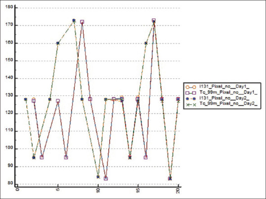
Comparison of pixel locations
The location of pixel with maximum count from Point spread function (PSF) of 140 keV and 364 keV matches with an excellent correlation on two separate studies [Graphs 1 and 3]. The difference in mean FWHM of PSF of two energies was significantly different from 0. The broadening of PSF profile of 364 keV can be explained by larger scatter events compared to 140 keV. Intraclass correlation of studies performed on two separate occasions under similar conditions showed a good correlation (k = 0.87), indicating that the procedure is reproducible and apparently not so operator dependent.
Discussion
Modern gamma-camera employs several correction data established in factory to improve nonuniformity and nonlinearity.[4] Basic performance parameters of gamma-camera are assessed using 99mTc source. Accurate MWSR indicates that the performance parameters such as pixel calibration and spatial linearity are not totally dependent on quantum efficiency of detector. Tuning for different radionuclide energies and calibration of gamma-camera is performed in factory setup, and limit of accuracy of spatial registration is established. Hence, MWSR is an optional test at the customer site.
Bergmann et al. studied the accuracy of MWSR using long lived 133Ba source (T½ 10.551 years) on three camera heads of different crystal thicknesses (9.5, 15.9, and 25.4 mm) with large rectangular field of views. 133Ba also known as “the mock 131I”, in its EC, γ mode of decay emits 80keV (34% abundance), 356keV (62% abundance), 303keV (18% abundance) and 384keV gamma rays. The authors used 80keV and 356 keV of 133Ba for the testing MWSR. The results were validated with measurements obtained from 67Ga source. The multiple window spatial registration errors obtained by the 133Ba method showed excellent reproducibility (standard deviation < 0.07 mm). Comparison between the results of 133Ba and 67Ga methods showed small differences with a correlation coefficient of 0.51 (p < 0.05) and were interchangeable.[5]
mTc pertechnetate and 131I-NaI are used to perform majority of the mandatory and optional NEMA acceptance tests. The only test that requires additional source procurement is MWSR. Given the pandemic circumstances, cost of 67Ga/201Tl/111In sources, time needed for importing and its implication on licensing, alternate method of MWSR procedure was conceived. In the present study, instead of mock-calibration source like 133Ba, a carefully prepared cocktail of 99mTc pertechnetate and 131I-NaI point source was used to conduct the test. The study demonstrated an excellent correlation between X and Y coordinates acquired on 99mTc and 131I energies in both detectors. The experiment repeated on consecutive days was reproducible indicating a logical and viable alternative to routine NEMA protocol using the costly 67Ga/201Tl/111In source. With the advancement in semiconductor detector gamma-camera, tests such as MWSR would have minuscule importance in future.
The objectives of performing acceptance tests in nuclear medicine facility should be:
To demonstrate and verify that the performance of installed instrument matches with factory specification under clinical simulation
To perform and record values of various quality control (QC) tests that form a baseline reference, so that the user can refer to it during the lifetime of the instrument
Hands-on training for the young nuclear medicine technologists, who might get once in a lifetime opportunity to witness acceptance tests.
There should be an agreement between the user and the manufacturer at the time of purchase regarding acceptance tests in terms of mobilization of phantoms, resources, and responsible manpower. The technical manpower should have adequate technical knowledge about the equipment and its operation, the purpose of each QC test, and its implications in clinical setting.
The technical person/team from the manufacturer should interact with nuclear medicine physicians and technical team (user), conduct the procedures, and demonstrate satisfactory results. The technical person should also know the alternate methods to perform the QC tests and apply those methods on a needed basis. Efforts should be taken to perform studies under ideal conditions, and the truthful results are documented. Even if the studies get delayed by a day or 2, attempt should be made to make sure that the user understands the performance capabilities of the instrument. The standard protocols documented in NEMA/IEC publications should guide the entire procedure. The user has all the rights to reject and advise repetition of tests if the procedure and results are not satisfactory.[6]
The manufacturer is responsible to make sure that the user is satisfied with list of procedures, conduct, and documentation of results. If the technical team of manufacturer works toward satisfying the licensing authority, the essence and objectives of acceptance tests will be lost. The entire procedure turns out stereotypical, and the purpose will just be to document the results under accepted limits.
Conclusion
Acceptance tests performed during equipment installation should be objective-driven, educative, and scientific, avoiding monotony yet adhering to the established guidelines such as NEMA. Optional tests such as MWSR must be cost-effective and should not delay the process of licensure. Dual-tracer method described in the present study is reproducible, accurate, cost-effective, and a swift logical alternative to routine NEMA procedure for evaluation of MWSR.
Financial support and sponsorship
Nil.
Conflicts of interest
There are no conflicts of interest.
References
- 1.National Electrical Manufacturers Association. NEMA Standards Publication NU 1-2007: Performance Measurements of Gamma Cameras. Rosslyn, VA: National Electrical Manufacturers Association; 2007. [Google Scholar]
- 2.IEC. IEC 60789: Medical Electrical Equipment – Characteristics and Test Conditions of Radionuclide Imaging Devices – Anger Type Gamma Cameras. Geneva: IEC; 2006. [Google Scholar]
- 3.Koo TK, Li MY. A guideline of selecting and reporting intraclass correlation coefficients for reliability research. J Chiropr Med. 2016;15:155–63. doi: 10.1016/j.jcm.2016.02.012. [DOI] [PMC free article] [PubMed] [Google Scholar]
- 4.Cherry S, Sorenson J, Phelps M. USA: Elsevier Science; 2003. Physics in Nuclear Medicine; pp. 235–9. [Google Scholar]
- 5.Bergmann H, Minear G, Raith M, Schaffarich PM. Multiple window spatial registration error of a gamma camera:133Ba point source as a replacement of the NEMA procedure. BMC Med Phys. 2008;8:6. doi: 10.1186/1756-6649-8-6. [DOI] [PMC free article] [PubMed] [Google Scholar]
- 6.Halama JR, Graham CD, Harkness BA, Kappadath SC, Madsen MT, Massoth RJ, et al. American Association of Physicists in Medicine. AAPM Report No. 177. Acceptance testing and annual physics survey recommendations for gamma camera, SPECT, and SPECT/CT Systems. [[Last accessed on 2022 Aug 15]]. Task Group No. 177 (TG 177), ISBN: 978-1-936366-68-2. Avalaible form: https://www.aapm.org/pubs/reports/RPT_177.pdf .