Abstract
Multielectrode arrays would benefit from intimate engagement with neural cells, but typical arrays do not present a physical environment that mimics that of neural tissues. We hypothesized that a porous, conductive hydrogel scaffold with appropriate mechanical and conductive properties could support neural cells in 3D, while tunable electrical and mechanical properties could modulate the growth and differentiation of the cellular networks. By incorporating carbon nanomaterials into an alginate hydrogel matrix, and then freeze-drying the formulations, scaffolds which mimic neural tissue properties were formed. Neural progenitor cells (NPCs) incorporated in the scaffolds formed neurite networks which spanned the material in 3D, and differentiated into astrocytes and myelinating oligodendrocytes. Viscoelastic and more conductive scaffolds produced more dense neurite networks, with an increased percentage of astrocytes and higher myelination. Application of exogenous electrical stimulation to the scaffolds increased the percentage of astrocytes and the supporting cells localized differently with the surrounding neurons. The tunable biomaterial scaffolds can support neural co-cultures for over 12 weeks, and enable a physiologically-mimicking in vitro platform to study the formation of neuronal networks. As these materials have sufficient electrical properties to be used as electrodes in implantable arrays, they may allow for the creation of biohybrid neural interfaces and living electrodes.
Keywords: bioelectronics, hydrogels, neuronal cultures, electrical stimulation, biomaterials
1. INTRODUCTION
Implantable multielectrode arrays are used to modulate electrically active tissues by recording and/or stimulation at the electrode sites[1–7]. These electrodes are traditionally composed of highly conductive materials, such as thin metal films. Although advances in photolithographic processing of these films have led to decreased feature sizes and increased electrode densities, the electrodes have limitations in terms of material conformability and chemical stability in aqueous environments, especially in applications of stimulation[8–13]. In contrast, polymers are flexible, biocompatible, and occasionally intrinsically conductive[14,15]. Further, this class of materials can be made porous and with high surface areas[16,17]. The latter is important when considering the emerging fields of biohybrid electronics and living electrodes, where cells are integrated directly into the electrodes to offer more biocompatible and stable interfaces, as the incorporated cells will be in contact with the host cells[18–20].
Initial biohybrid electronics studies demonstrated that neural and glial cells could remain viable for up to 4 weeks when incorporated in polymer-coated metals or conductive polymers, such as polypyrrole (PPy), with an increased neurite outgrowth in PPy as compared to the coated metal electrodes[21–23]. Soon after, PPy was combined with polystyrenesulfonate (PSS) to be electrochemically deposited as a high-surface area ‘fuzzy’ electrode coating to further improve cell integration[24,25]. Now, poly(3,4-ethylenedioxythiopene) is doped with PSS, or commonly known as PEDOT:PSS, and can be electrodeposited into small, confined microchannels for equally ‘fuzzy’ but also more mechanically compliant surfaces[26–28]. However, despite modifications of PEDOT:PSS and PPy systems, including incorporation into a hydrogel matrix to provide better cell interfaces, these composites have limitations. The porous nature of these conductive hydrogels is minimal which results in limited ability for cells to integrate and migrate through the matrix. Additionally, the mechanical properties of existing scaffolds are vastly different from native neural tissues, as the composites are more than 1000x stiff than the tissue[29,30] and unlike living tissues, demonstrate no viscoelasticity[31–33]. In contrast, viscoelastic hydrogel matrices embedded with minimal amounts of conductive additives can match the properties of biological tissues while demonstrating sufficient conductivity to record and/or stimulate the underlying tissue with a signal-to-noise ratio >10[34].
Here, we investigate how the integration and differentiation of neural progenitor cells (NPCs) can be affected by changing the mechanical and electrical properties of conductive, porous hydrogels (Figure 1A). The mechanical and electrical properties of the scaffolds can be independently tuned to investigate how each can affect the growth and differentiation of NPCs for more than 12 weeks. Additionally, these high surface area scaffolds (Figure 1B) enable the application of electrical stimulation, providing a platform to investigate its effects on NPC differentiation, while also altering the mechanical properties to direct cell phenotype and network formation. These electrically conductive, viscoelastic, and porous scaffolds are facile to fabricate (Figure 1C), and can recapitulate important physiologic properties, thus offering advancements to biohybrid electronics and neural interfaces.
Figure 1: A porous biomaterial scaffold with embedded carbon nanomaterials.
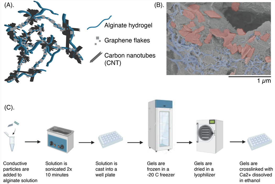
(A) Schematic of the scaffold, with a porous matrix of alginate (blue) that mechanically traps conductive carbon nanomaterials such as graphene flakes (GF, gray squares) and/or carbon nanotubes (CNT, black lines). (B) Scanning electron microscopy (SEM) micrographs of the scaffold, with the alginate left gray, the GFs falsely-colored in red, and the CNTs falsely-colored in blue. Scale bar: 1 μm. (C) Schematic showing the fabrication of the porous scaffolds.
2. RESULTS AND DISCUSSION
An electrically and mechanically tunable porous scaffold
To create bioelectronic hydrogel scaffolds with the mechanical profiles of neural tissues, an alginate matrix was mixed with conductive nanomaterials. A previously reported method to fabricate viscoelastic electrodes was modified[34] in order to preserve the viscoelastic, tissue-like mechanics of the alginate hydrogel, and to further minimize the amount of high aspect ratio additives added to the scaffold. The approach involved the freezing of the formulations before hydrogel crosslinking, to both create porosity and reduce the amount of conductive additives needed to achieve percolation. During the freezing step, ice crystals were formed and the non-soluble conductive additives confined to the polymer solution surrounding the ice. When the ice was removed and the porous composition crosslinked, the concentrated additives could form an electrically percolating path (Figure S1).
As the gel scaffolds were to be seeded with cells, the properties of the gels were targeted to match the properties of neural tissues, with G’<10 kPa, tan(δ)>0.2, and a conductivity of σ>3 S/m for sufficient recording and/or stimulation of the incorporated neurons[29,34–36]. To understand how the scaffold physical properties changed with increasing amounts of carbon nanomaterials, the local and bulk mechanics were assessed using nanoindentation (Figure 2A, 2B) and rheology (Figure 2C). Compositions at different concentrations of alginate, and at different additive compositions of graphene flakes (GF) and carbon nanotubes (CNT) between 0 and 1% total carbon content were compared. In our previously reported work, we found that scaffolds with both GF and CNT had greater conductivity than scaffolds with similar total carbon content but with just one of the additives. Scaffolds with GF content from 0-0.26% and CNT content from 0-0.997% were fabricated to ensure the material was easy to handle, mechanically stable, and with less variability in the distribution of conductive particles, as these formulations would later incorporate cells.
Figure 2: Electrical properties of the scaffold can be adjusted by varying amounts of each carbon nanomaterial, while keeping mechanical properties largely consistent.
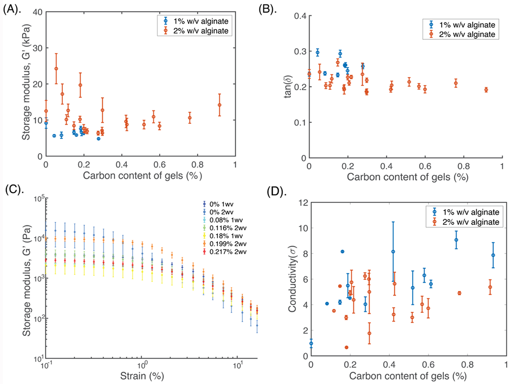
(A) Quantification of the storage modulus (G’), and (B) tan(δ) of the scaffolds with varying amounts of total carbon (graphene flakes and carbon nanotubes) using nanoindentation analysis (N=6 independent gels, n>5 measurements per gel). Gels with 1% (blue) and 2% (red) w/v alginate content are compared. Mean and standard error are shown for each graph. (C) Quantification of the bulk G’ versus % strain, with varying amounts of carbon (%) and with either 1% or 2% w/v alginate. N=4 independent gels for each composition. Legend (right) denotes the alginate w/v % of the composite, and the total amount of additive in the scaffold (%). (D) Quantification of gel conductivity with varying amounts of carbon, for 1% (blue) and 2% (red) w/v alginate. N=5 independent gels for each composition, with n>12 measurements per gel. Mean and s.d. are shown for each graph.
The local mechanical properties across the different gels were similar, with all formulations softer than 30 kPa (Figure 2A). Generally, the 2% w/v alginate formulations had larger moduli, with increased variability across the different samples. The tan(δ), in contrast, was larger, and thus the gels were more viscoelastic, for the 1% w/v alginate samples, although interestingly the standard deviation across all samples was less than that of the G’ measurements (Figure 2B). When the bulk mechanical properties were compared, the mechanical properties changed by less than an order of magnitude over all the tested formulations (Figure 2C).
The electrical properties of the formulations were also compared (Figure 2D). All values were between 4-10 S/m, and more conductive than the porous gels without any additives (<1 S/m). When compared to the nonporous formulations of the same compositions, the latter were more than 2 orders of magnitude less conductive (Figure S2). For the porous gels, formulations with 1% w/v alginate were slightly more conductive than the 2% w/v gels, with slightly higher variability. These gels were also more fragile, and were more likely to break when handled (Figure S3). The variability in mechanical and electrical properties of gels likely related to the fabrication process, which involves simple mixing and mechanical suspension of the additives in the polymer solutions; the resulting random distribution of particles during mixing and freezing steps likely led to some variability in particle distributions.
Gel formulations with less than 0.4% carbon additives in an alginate matrix of 1.5% and 2% w/v were able to meet the desired mechanical and electrical properties, and were used in all the following cell studies.
Scaffolds maintain cell viability and neuronal cell network formation
D1 mesenchymal stem cells (D1 MSCs) from mice were first incorporated into viscoelastic RGD-alginate scaffolds with varying amounts of conductive additives to assess their compatibility with cells. The cells distributed within the pores of the scaffolds (Figure 3A(i)), and maintained high viability across all scaffold conditions after 2 days (Figure 3A(ii)). Cell morphology changed slightly on the gels with the highest amount of CNT (0.23%, 0.26%), which suggested that the gel composition could affect the cells by increasing the number of D1 MSCs which had protrusions (Figure S4).
Figure 3: Porous conductive scaffolds can be tuned to support cell cultures of D1 MSCs and primary neuronal cells.
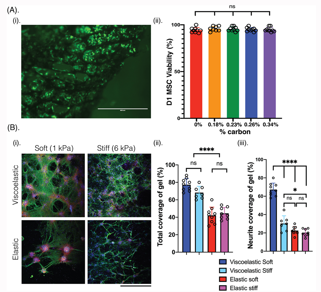
(A) (i) Photomicrograph of a 0.23% carbon content porous scaffold (black) seeded with D1 mesenchymal stem cells (D1 MSCs) after 2 days. Cells are stained using a live (green, calcein)/dead (red, ethidium) assay. Scale bar: 400 μm. (ii) Percentage of D1 MSCs that remain viable on viscoelastic scaffolds with varying amount of carbon content (% content). Mean and s.d. are plotted for each composition, with at least 9 gels per condition. (B) (i) Photomicrographs of primary rat neurons and rat glial progenitor cells seeded for 2 weeks in porous alginate-only scaffolds of different viscoelasticity (viscoelastic, elastic) and modulus (1 kPa, 6 kPa). Cells are stained for Tuj1 (green), phalloidin (red), MBP (white), and Hoescht (blue). Scale bar: 240 μm. (ii) Quantification of the total coverage of scaffold surface area by both cell types, and (iii) quantification of the neurite coverage of scaffold surface area. Mean and s.d. plotted for each condition. N=3 independent gels, with at least 8 field of views compared for each condition. All numerical data are presented as mean ± s.d. (one-way analysis of variance (ANOVA) and Tukey’s honestly significant difference (HSD) post hoc test: ***p < 0.0001, 0.01 < * P < 0.05, non-significant (n.s.) P > 0.05).
Neural cells were next cultured on scaffolds of different viscoelasticity (viscoelastic, tan(δ)=0.3-0.35; elastic, tan(δ)=0.1-0.15) and mechanical modulus (soft, 1 kPa; stiff, 6 kPa) (Figure S5). Primary neuronal cells alone formed networks on the various scaffolds, with the densest networks resulting on the viscoelastic soft materials, but the networks were relatively sparse. To promote more robust network formation, a 2:1 ratio of rat primary neurons and rat glial progenitor cells (GPCs) were then added into porous scaffolds. Here, the scaffold mechanical properties were compared rather than electrical properties, to first assess the role of mechanical environment on the resulting cellular networks (Figure 3B(i)). Networks of lattice-like structures formed on all scaffolds, with a substantially increased amount of substrate surface area covered by cells in all of the gel conditions (Figure 3B(ii)), as compared to coverage on a control of poly-d-lysine coated glass (Figure S6). In both viscoelastic gels, the cell coverage was substantially higher than on the elastic gels (Figure 3B(ii)). Additionally, the neurite-only coverage of the scaffolds was almost double on the viscoelastic soft substrates, which best matched the neural tissue mechanical properties, as compared to any other gel (Figure 3B(iii)). In the elastic gels, there were more frequent and larger aggregates of cells which had some neurite projections. The soft gels demonstrated phalloidin-positive cells localized at the nodes around the pores, perhaps suggesting these cells provided structural support to the neurite networks. These phalloidin-positive cells formed larger aggregates on the soft elastic gels, with a much smaller presence on the elastic stiff gels. Finally, staining for myelin basic protein (MBP, white) revealed few GPCs in all cultures, with an increase on the soft viscoelastic gels.
Viscoelastic and conductive scaffolds promote NPC differentiation into multiple lineages
Neural progenitor cells (NPCs) derived from human embryonic stem cells (hESCs) were next seeded onto scaffolds due to their high proliferative ability and multi-lineage potential to differentiate into neurons, astrocytes, and oligodendrocytes (Figure S7). In addition to formation of various cell types important to support neuronal networks at high scaffold densities, the human-derived NPCs allowed for a better platform to study the development of human neural cells and tissues, and offered a better transition to assess the integration of biohybrid electronics in implantable multielectrode arrays. NPCs were first added on top of the scaffolds to assess the compatibility of cells on the materials in 2D after 2 weeks (Figure S8) and 4 weeks (Figure S9). Both viscoelastic and elastic scaffolds, that were either soft (1 kPa) or stiff (6 kPa) were compared, and the softer, viscoelastic gels allowed for increased neuronal differentiation and neurite coverage of the scaffold.
Next, NPCs were transfected with tdTomato to allow for easier visualization, and cultured on (2D) to assess viability for 4 weeks (Figure S10), and then in (3D) viscoelastic and elastic substrates (2D) and scaffolds (3D) of similar stiffness (1 kPa), with varying carbon content for 6 weeks. First, NPCs were seeded on top of nonporous gels with no carbon additives to evaluate how 2D cultures would form on viscoelastic and on elastic substrates (Figure 4). After 1 week in culture, NPCs had formed aggregates which were larger on the elastic gels, and slightly less circular with some sprouting on the viscoelastic gels (Figure 4A). These aggregates were positive for stem cell markers (Nestin: green, Sox2: white). At 5 weeks, the viscoelastic substrates contained far fewer stem positive cells which were distributed throughout the scaffold, rather than in aggregates. In contrast, the elastic gels maintained cell aggregates, which were smaller in size than at 1 week, but with a similar organization of stem positive cells in the periphery of the clusters. Further, the decrease in stem positive cells at week 5 was less pronounced in elastic gels. Analysis of differentiated neuronal markers (Tuj1:green, NeuN: white) revealed neuronal cell coverage over most of the viscoelastic substrates, with only small aggregates of cells, many of which were not positive for the differentiated markers, on the elastic gels (Figure 4B).
Figure 4: Neural progenitor cells (NPCs) can be integrated onto the scaffolds (2D) for multiple weeks.
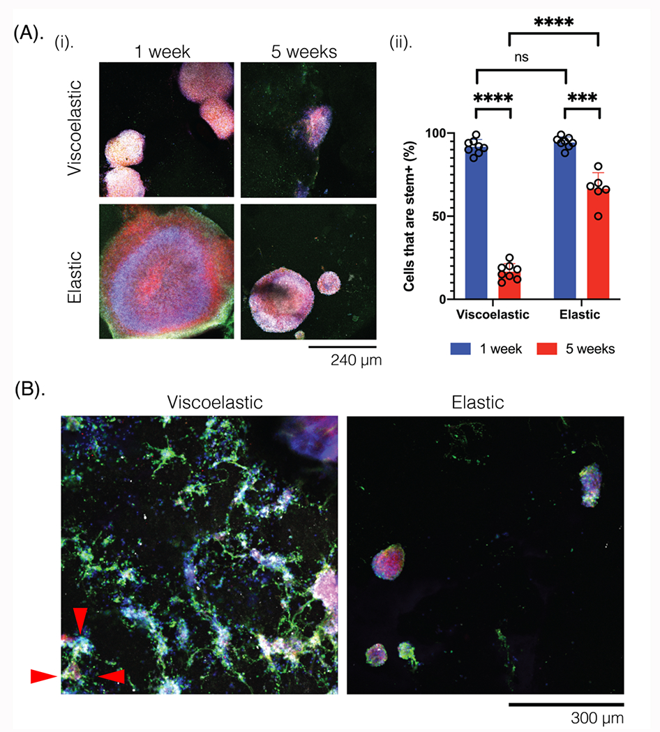
(A) (i) Photomicrographs of NPCs seeded onto scaffolds of different mechanical properties (viscoelastic, elastic), and with no carbon additives. Cells are compared after 1 week (left) and 5 weeks (right) in the scaffold, and stained for Nestin (green), Sox2 (white), NPC-tdTomato (red), and Hoescht (blue). Scale bar: 240 μm. (ii) Quantification of the stem-positive cells (Nestin+, Sox2+) after 1 or 5 weeks, on the viscoelastic and elastic scaffolds. N=3 gels per condition and at least 6 field of views for each condition. Numerical data are presented as mean ± s.d. (one-way analysis of variance (ANOVA) and Tukey’s honestly significant difference (HSD) post hoc test: ****P < 0.0001, 0.0001 < ***P < 0.001, non-significant (n.s.) P > 0.05). (B) Photomicrographs of NPCs after 5 weeks in viscoelastic (left) and elastic (right) substrates, stained for differentiated neural markers Tuj1 (green), NeuN (white), NPC (red), and Hoescht (blue). Red triangles indicate the sprouting behavior observed on the viscoelastic scaffolds. Scale bar: 300 μm.
Next, the neurite network formation (Tuj1: green) and cell coverage were qualitatively and quantitatively compared across different viscoelasticity and scaffold conductivity over time for cells seeded in 3D (Figure 5A). In addition to differences in mechanical properties (viscoelastic, elastic) of the scaffolds, the conductivity and amount of carbon additives were compared. As the scaffold conductivity increased, the percentage of aggregated cells, which was defined by a bundle of cells larger than 100 μm in diameter, decreased and cells instead distributed around the pores (Figure 5B). Additionally, as observed previously, the NPCs formed more aggregates on the elastic gels as compared to the equivalent viscoelastic formulation, with a more pronounced difference at higher carbon contents. The number of neuronal cells (Tuj1+) increased with the scaffold carbon content in both the viscoelastic and elastic gels (Figure 5C). Viscoelastic gels generally contained more neuronal cells than the equivalent elastic formulations although at the highest carbon content scaffolds the neuron content was similar.
Figure 5: Neurons form less cellular aggregates on more conductive scaffolds and neurites span the scaffold architecture.
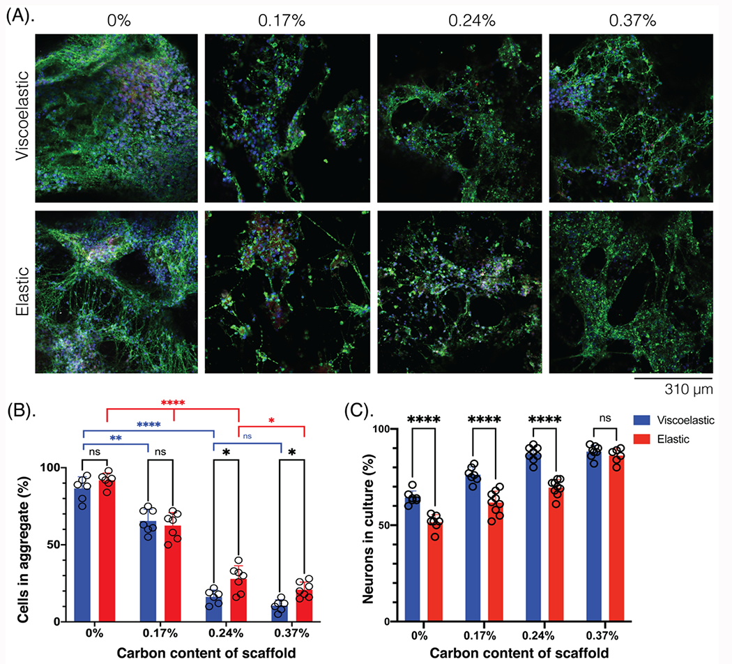
(A) Photomicrographs of NPCs in the scaffolds of different mechanical properties (viscoelastic, elastic) and scaffold carbon content (%), compared after 6 weeks in culture and stained for neuronal markers. Tuj1 (green), NeuN (white), NPC (red), Hoescht (blue). Scale bar: 310 μm. (B) Quantification of the number of cells that have aggregated together (aggregate diameter > 100 μm) across scaffold carbon content (%) and mechanical properties (viscoelastic: blue; elastic: red). At least 5 field of views compared for each condition. (C) Quantification of the neurons (Tuj1+) in culture (%), across scaffold carbon content (%) and mechanical properties (viscoelastic: blue; elastic: red). At least 7 fields of view compared for each condition. All numerical data are presented as mean ± s.d. (one-way analysis of variance (ANOVA) and Tukey’s honestly significant difference (HSD) post hoc test: ****P < 0.0001, 0.001<**-<0.01, 0.01 < *P < 0.05, non-significant (n.s.) P > 0.05).
When the scaffolds were assessed for astrocytes (GFAP: white), the distribution and size of these cells was also different across scaffold mechanics and conductivity (Figure 6A). The astrocytes were always in a plane below the neurons, and were both smaller and more abundant on the viscoelastic scaffolds (Figure 6B). On viscoelastic scaffolds, the astrocytes also formed long projections that spanned underneath neurites. Further, the cells were more likely to be found along the neurites at the perimeter of cells, rather than in the center of the clusters. There were fewer GFAP+ cells on the elastic scaffolds, but the cells were also much larger and localized in the center of aggregates. There was a significant increase in astrocytes on the higher carbon content viscoelastic scaffolds. Interestingly, there was no significant change in the astrocytes across the different conductivities in the elastic scaffolds.
Figure 6: Astrocyte differentiation after 6 weeks on scaffolds is impacted by scaffold mechanical and electrical properties.
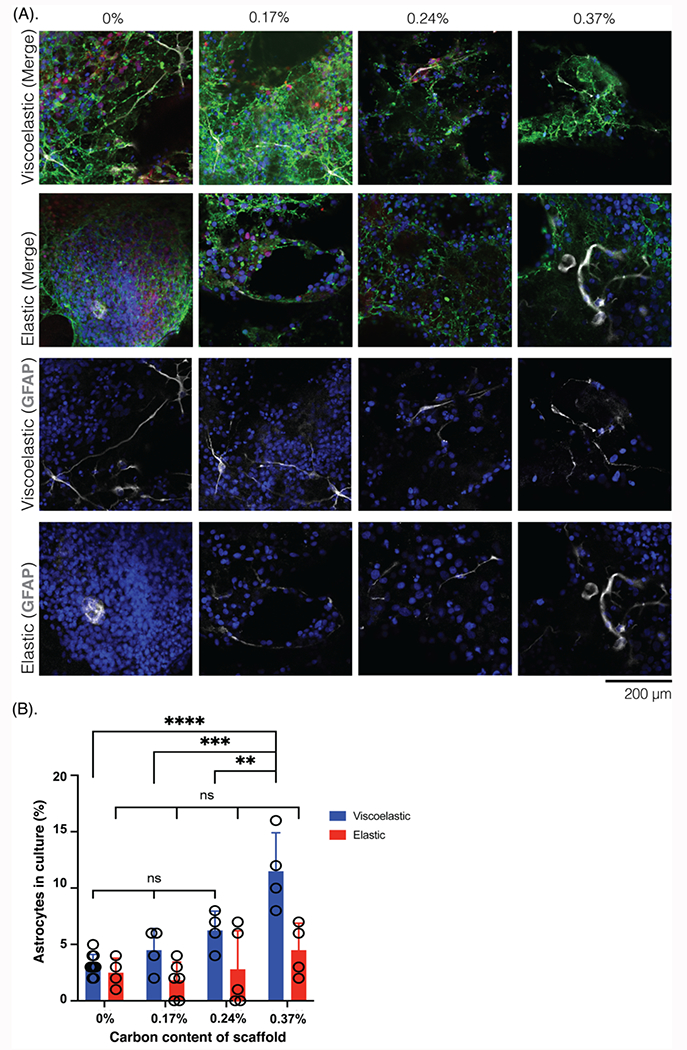
(A) Photomicrographs of NPCs in the scaffolds of different mechanical properties (viscoelastic, elastic) and scaffold carbon content (%), compared after 6 weeks in culture and stained for astrocyte marker, with neurites visualized as well. Top 2 rows, merged images: Tuj1 (green), GFAP (white), NPC (red), Hoescht (blue); bottom 2 rows, GFAP and Hoescht, only. Scale bar: 200 μm. (B) Quantification of the astrocytes (GFAP+) in the cultures (%), across scaffold carbon content (%) and mechanical properties (viscoelastic: blue; elastic: red). At least 6 field of views compared for each condition. All numerical data are presented as mean ± s.d. (one-way analysis of variance (ANOVA) and Tukey’s honestly significant difference (HSD) post hoc test: ****P < 0.0001, 0.0001 < ***p < 0.001, 0.001<**P<0.01, non-significant (n.s.) P > 0.05).
The differentiation of NPCs to oligodendrocytes, which produce the fatty myelin sheaths that insulate axons, was also assessed (MBP: white) (Figure 7A). There was more total myelin as well as longer myelinated segments on the viscoelastic gels than on any of the elastic gels. At the highest carbon content on viscoelastic scaffolds, the length of myelin spanned almost 400 μm (Figure 7B). Myelin thickness, as well as continuous segments, increased on the more conductive viscoelastic substrates, but there were no substantial changes on the elastic scaffolds (Figure 7C). At 0.24% carbon content, the myelin amount was not statistically different but as the cells formed fewer aggregates and there were more neurons, the myelin was thicker and was found along neurites rather than sporadically in aggregates (Figures 7A, 7C). This was visible on the elastic scaffolds, as well, even though the total length of myelin was quite low. At the highest carbon contents (0.37%), the myelin was more abundant. Myelin was readily visualized with a Z-stack 3D reconstruction (Figure S11), as the gels were each ~1 mm thick and had networks of cells that spanned the length of the gel. Analysis of gels at week 2 confirmed there were no myelinated segments at this time point (Figure S12), and additional images show the progress of myelination on viscoelastic and elastic scaffolds (Figure S13).
Figure 7: Myelination length and quantity is impacted by scaffold mechanical and electrical properties.
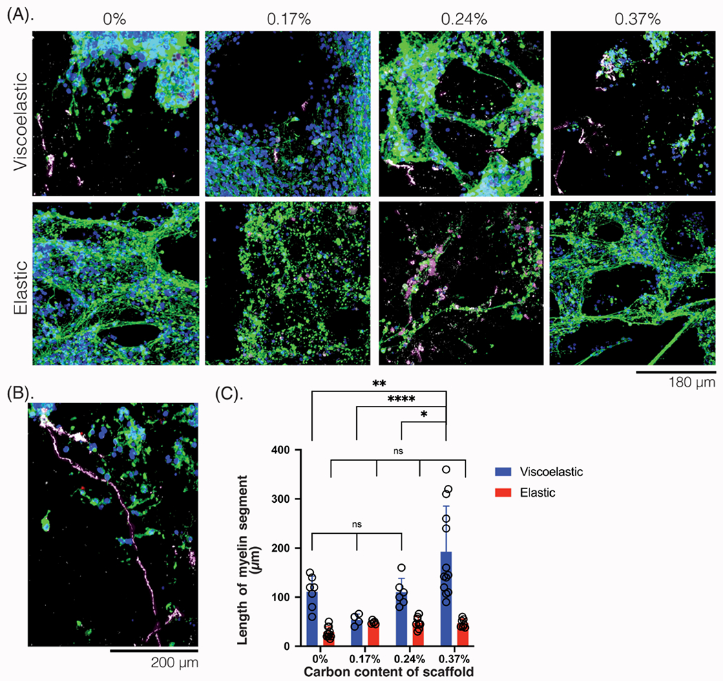
(A) 3D reconstructions of photomicrographs of NPCs in the scaffolds of different mechanical properties (viscoelastic, elastic) and scaffold carbon content (%), compared after 6 weeks in culture and stained for oligodendrocyte marker. Tuj1 (green), MBP (white-magenta), NPC (red), Hoescht (blue). Scale bar: 180 μm. (B) Photomicrograph of a viscoelastic scaffold with 0.37% carbon content, showing myelinated (white-magenta) neurites (green) spanning the entire length of the scaffold. Scale bar: 240 μm. (C) Quantification of the length of myelin (white-magenta, μm) across scaffold carbon content (%) and mechanical properties (viscoelastic: blue; elastic: red). At least 5 field of views compared for each condition. All numerical data are presented as mean ± s.d. (one-way analysis of variance (ANOVA) and Tukey’s honestly significant difference (HSD) post hoc test: ***P < 0.0001, 0.001 < **P < 0.01, 0.01 < * P < 0.05, non-significant (n.s.) P > 0.05).
Both viscoelastic (Figure 8A) and elastic (Figure 8B) scaffolds with 0.24% carbon content were imaged at a larger field of view, to compare the NPC differentiation and distribution in the material. The viscoelastic scaffolds demonstrated a neurite network that spanned the entire scaffold, without filling the pores of the biomaterial and with regions of myelination throughout the scaffold. In the elastic scaffolds, there were larger aggregates of cells without neurites, and with a decreased percentage of neurites on the scaffold. There were a few regions of myelination on the elastic scaffold, which were closer together rather than distributed throughout the scaffold.
Figure 8: NPC differentiation and localization is affected by scaffold mechanical and electrical properties.
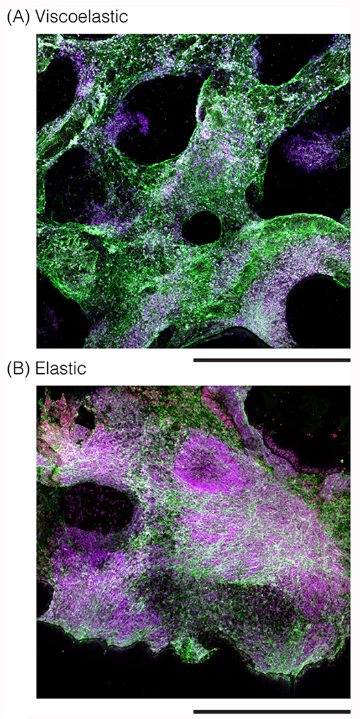
(A) 3D reconstructions of photomicrographs of NPCs in a viscoelastic 0.24% conductive scaffold, and (B) 3D reconstructions of photomicrographs of NPCs in an elastic 0.24% conductive scaffold. Cells stained after 6 weeks for Tuj1 (green), MBP (white), NPC (red), Hoescht (blue) and imaged over a larger field of view. Scale bar: 450 μm.
Electrical stimulation of the conductive scaffolds enhances NPC differentiation
The impact of exogenous electrical stimulation on NPC growth and differentiation was next explored. Based on the earlier results, only viscoelastic scaffolds were utilized, and scaffolds with no carbon, 0.23%, 0.26%, and 0.28% were explored. This reduced carbon range was chosen as these scaffolds offered similar neuron and astrocyte benefits as the 0.37% carbon contents, but were more mechanically stable. While the mechanical properties of these formulations were not significantly different (Figure 2A, 2B), the conductivity was slightly different depending on the exact amount of GF and CNT added. The narrow range in carbon content was explored to see how the amounts of additives could affect the viability of NPCs as external stimulation is applied. Square wave pulses were applied for 15 minutes to all the scaffolds, either daily or every other day, for a duration of 8 days, (Figure 9A). After 6 days in vitro (DIV), scaffolds that received stimulation daily had very few viable cells (Figure 9B). In contrast, viable cells that infiltrated throughout the entire scaffold were found with stimulation every other day (Figure S14).
Figure 9: Application of exogenous electrical stimulation on NPC-laden scaffolds to modulate resulting networks.
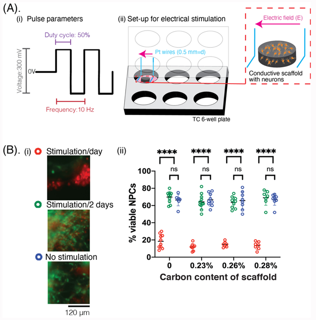
(A) (i) Schematic showing the parameters of the electrical pulses applied to the scaffold. (ii) Schematic showing the set-up of electrical stimulation. The conductive scaffold (gray) is cell-laden (yellow) and placed between two parallel platinum wires (blue), which have been machined to fit into the lid of a 6-well tissue culture plate. Electric fields are generated across the scaffold as electrical pulses are applied (pink arrow). (B) (i) Photomicrographs showing the NPCs in viscoelastic-only scaffolds after 6 total days of the stimulation paradigm. Cells are stained using a live (green, calcein)/dead (red, ethidium) assay. Scale bar: 120 μm. (ii) Quantification of the viability (%) of cells in the scaffold, comparing cells that received daily stimulation (red), stimulation/2 days (green), or no stimulation (blue) over a 6 day study, with scaffolds of different carbon content for each stimulation condition.
After stimulation was completed, the cells were left in the scaffolds for a total of 51 DIV and analyzed for NPC differentiation to neurons (Figure 10A) and astrocytes (Figure 10B), and myelination (Figure 10D). In gels that had been stimulated daily, there were many cells that were not positive for any of these differentiation markers, with sparse Tuj1 networks and no myelin staining. On scaffolds that had received stimulation every other day, there was a significant increase in the number of differentiated neurons (Figure 10A), and this increase was further amplified on scaffolds with carbon additives. There was also a significant increase in the differentiation into astrocytes, especially on the scaffolds with added carbon. Astrocytes were again located in planes below the neurons, but formed much longer protrusions and networks than on gels that had received no stimulation (Figure 10B). Astrocytes were in the center of cell aggregates (Figure 10C), rather than in the periphery when there was no stimulation. In many regions of aggregated cells, the astrocyte protrusions were found perpendicular to the neurites.
Figure 10: Evaluation of neurons, astrocytes, and oligodendrocytes after exogenous electrical stimulation of NPC-laden scaffolds.
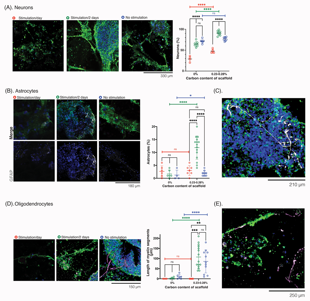
(A) Photomicrographs of the cells at 51 days in vitro (DIV), after following the stimulation paradigm for the first 8 days of culture, and stained for neuronal markers. Tuj1 (green), NPC (red), Hoescht (blue). Scale bar: 330 μm. Quantification (right) of neurons in the cultures (%), across each stimulation condition. (B) Photomicrographs of the cells at 51 DIV, after receiving 8 days of the stimulation paradigm, stained for astrocytic and neurite markers. Top row: merged images, Tuj1 (green), GFAP (white), NPC (red), Hoescht (blue); bottom row: GFAP and Hoescht, only. Scale bar: 180 μm Quantification (right) of the astrocytes (%) in the cultures, comparing different scaffold carbon content and different stimulation paradigms (daily: red, green: every 2 days, blue: no stimulation). (C) Photomicrograph of cells at 51 DIV, after receiving stimulation every other day in the first 8 days, to show the size and distribution of astrocytes over a larger field of view. Tuj1 (green), GFAP (white), NPC (red), Hoescht (blue). Scale bar: 210 μm. (D) Photomicrographs of cells at 51 DIV, after receiving 8 days of the stimulation paradigm, and stained for oligodendrocyte and neurite markers. Tuj1 (green), MBP (white-magenta), NPC (red), Hoescht (blue). Quantification (right) of length of myelin (μm) in each condition for different stimulation paradigms (daily: red, green: every 2 days, blue: no stimulation). (E) Photomicrograph of cells at 51 DIV, after receiving stimulation every other day in the first 8 days, to show the size and distribution of myelination in a smaller field of view. Tuj1 (green), MBP (white-magenta), NPC (red), Hoescht (blue). Scale bar: 250 μm. All numerical data are presented as mean ± s.d. (one-way analysis of variance (ANOVA) and Tukey’s honestly significant difference (HSD) post hoc test: ***P < 0.0001, 0.0001 < ***P < 0.001, 0.001 < **P < 0.01, 0.01 < *P < 0.05, non-significant (n.s.) P > 0.05).
Despite changes in the astrocyte number and phenotype, electrical stimulation every other day had no impact on the amount of myelin found in the gels (Figure 10D). The myelin spanned ~100 μm and only along a few of the neurites (Figure 10E), as observed in Figures 7A, 7C. This could relate to the specifics of electrical stimulation, as the exogeneous electrical pulses were generated by a function generator. While designed to have positive and negative components that spanned the entire duty cycle, the pulses were not perfectly biphasic. A biphasic stimulator could offer more compatible pulses for stimulation, and further improve the differentiation and myelination capabilities of the oligodendrocytes[37–40].
Interestingly, while the application of exogenous electrical stimulation did not affect the myelination of the neurites, the inherent electrical properties of the scaffold substantially increased the presence of neurons (Figure 10A), presence of astrocytes (Figure 10B), and the amount of myelination (Figure 10D). From the 0% carbon to 0.23-0.28% scaffolds, the % neurons in the culture increased from ~60% to ~80% respectively, and the % astrocytes increased from ~2% to ~13%, respectively. Additionally, while scaffolds with no carbon additives had myelin segments < 50 μm, the scaffolds with 0.23-0.28% carbon content had many myelin segments which were > 100 μm. As the inherent conductivity already had an influence on the composition of the cultures, the further exploration of electrical stimulation parameters could further enhance these differences.
3. CONCLUSIONS
We report a highly tunable biomaterial scaffold which can support the growth, proliferation, and network formation of various cell types, from MSCs to neurons and NPCs. When incorporating NPCs into the scaffolds, the cells were able to differentiate into different neural cell lineages. Further, NPCs were able to form neuronal networks with regions of myelination and structural support by astrocytes. The porous scaffolds overcome many existing limitations in biohybrid electronics, such as the use of materials with mechanical properties that are very different from those of native neural tissue, minimal ability for neuronal cells to form 3D networks, and the use of metals which release ions or apply high charge injection of current into the cultures.
while enabling the investigation of the roles of mechanical and electrical environment(s) in the development of neurons. As mechanical and electrical properties may have different effects in the formation of each cell type and the resulting cellular networks, the platform allows for independent investigation of each stimulus.
In terms of the mechanical properties of the scaffold, the modulus has been shown to influence network formation of neurons and astrocytes[20,41–43], but little work has been done to investigate the impact of the viscoelasticity of scaffolds on neural cells. The more elastic hydrogel formulations contained more and larger aggregates of neural cells. This could be because the cells are unable to remodel these scaffolds. The extracellular matrix, in contrast, is viscoelastic in nature and is continuously modulated by cells. As the viscoelastic scaffolds are able to better recapitulate the mechanical modulus and properties of the extracellular matrix, neurons may be able to better spread on the material and form networks that mimic those found in vivo.
In terms of electrical properties, scaffolds of higher conductivity tend to contain more CNTs which form dense bundles, and increase the surface roughness of the scaffolds. Past studies have demonstrated improved integration of neuronal cells onto materials with high surface area, such as by micro- and nano-topographies[44–47]. It has been reported that these rougher materials regulate and activate the YAP/TAZ pathway[48,49], and increase paxillin-mediated adhesion[45]. As the latter binds to proteins involved in reorganizing the actin cytoskeleton, and as the neuronal growth cone involves actin dynamics, the increased roughness of the more conductive scaffolds could facilitate the formation of neuronal networks. Further, there are multiple additives and hydrogels which would be compatible with the fabrication method, thus allowing for increased tunability of the mechanical and electrical properties of the scaffolds and further regulation of these mechanosensors.
Since electrical pulses can be applied without damaging the biomaterial networks, or displacing any conductive particles, the scaffolds can be used to deliver exogenous electrical stimulation and study how electrical pulses can be used to differentiate or guide the NPCs. Future work could investigate how different pulse profiles could best differentiate NPCs into specific lineages, and further promote the differentiation into neurons and astrocytes. Additionally, since the described biomaterial enables the formation of 3D neuronal co-cultures in physiologically-mimicking environments, the materials offer a more translational platform to assess the influence of drugs and other small molecules on the networks.
The porous, conductive alginate scaffolds can support neural cells for more than 12 weeks, while offering sufficient electrical properties to be used as the electrodes in implantable multielectrode arrays. This would enable biohybrid electronics which offer a tissue-mimicked interface, while remaining viscoelastic and able to conform to the site of implantation. These materials can be further employed for tissue engineering applications both in vitro and in vivo to modulate neuronal cultures and tissues.
4. EXPERIMENTAL SECTION
Fabrication of conductive hydrogels:
To prepare the porous gels, varying amounts of conductive nanoparticles were mixed into 1%, 1.5% or 2% (w/v) RGD-alginate dissolved into DiH2O. Alginate with two different molecular weights was used to form gels with ‘elastic’ or ‘viscoelastic’ properties, respectively: High Molecular Weight (HMW) alginate Protonal LF10/60, and Low Molecular Weight (LMW) alginate Protonal LF10/60 3mRad irradiation. RGD-alginate was prepared by coupling the oligopeptide GGGRGDSP (Peptides International) to the sterile alginate using carbodiimide chemistry, as previously described[50].
The mixture was briefly vortexed before being placed in a sonicator bath for 10 minutes, twice (solutions were briefly vortexed between each sonication step). The solution was then cast into tissue culture plates (typically 12, 24, or 48 well plates depending on the number of cells available) before being frozen at −20 C. Once frozen, the plates were transferred to a lyophilizer (Freezone, Labconco). Gels were cross-linked by ionic crosslinking with Ca2+ dissolved in ethanol at a concentration of 450mM.
Briefly, to make conductive formulations, the particles were mechanically suspended into the hydrogel matrix and then vortexed/sonicated as described above. Two types of carbon nanomaterials were used to create the conductive hydrogels: multiwalled carbon nanotubes (CNT) (Nanocyl NC3100) and graphene flakes (GF) (Sixonia, Germany at a concentration of 2.143 mg/mL in water without any additives). The CNTs had a diameter of 10 nm and a length of 1.5 μm, and the GF were 1-2 μm in lateral dimensions. We include the relative amounts of GF and/or CNT added to each gel composition, as well as the amount of hydrogel and the total % carbon in Table S1.
Mechanical measurements:
Scaffolds were characterized using nanoindentation and rheology. In both cases, at least 4 gels per condition were tested. The local, surface properties of the gels were measured by nanoindentation, using a G200 nanoindentator (Keysight Technologies) with a spherical tip (diameter: 400 μm). Mechanical characterization of the material was done at room temperature using hydrated gels. At least ten measurements were taken per gel, each at different locations, and gels were rehydrated every five measurements to avoid drying. The elastic modulus (G′), storage modulus (G″) and tan(δ) were recorded. For both the local and bulk properties, the G’, G”, and tan(δ) were characterized.
Rheological characterization was done with a DHR-2 TA Instrument. Conductive hydrogels discs of 20 mm in diameter were placed on the rheometer, and a 20 mm flat plate geometry was used to measure the samples across a strain sweep and with a constant frequency at 1 Hz, and then a frequency sweep at 0.5% strain. At least 3 samples for each gel composition were characterized, and the samples were >1 mm thick.
In all cases of local and bulk mechanical characterization, the samples were measured in a hydrated state (e.g. cell media, PBS with 10 mM CaCl2). They were removed from their mold, placed on a clean glass slide, and any excess liquid was wicked away. To ensure that the samples were not drying out, we changed the sample every 6 minutes.
Electrical measurements:
The conductivity of the gels was obtained by a 4-point probe and resistance meter to measure the sheet resistance, Rs, of the material. 4 insulated wires were soldered to pins of a header, with a spacing of 2.54 mm between adjacent pins. This probe spacing was more than 10x smaller than the gel diameter to avoid any edge effects. The two outer probes conduct current, and the inner two probes are used to measure the voltage change. From Rs, conductivity can be calculated:
where t: thickness of the gel, C: correction factor defined by the geometry of the sample with respect to the spacing of the probes and can be calculated using the following reference[51], and σ: conductivity of the gel. The sheet resistance was measured at 10-20 locations on the gel, and at least 3 gels per composition were measured before plotting the average conductivity for each formulation.
Porosity of the conductive hydrogels:
Previously, we reported on the porosity of the conductive scaffolds, and found that their porosity was minimally affected between 0-3% total carbon content (Reference [34], Figure S15). The porosity between all formulation was between 75-92%, with a slight decrease in porosity as higher amounts of CNT were added. Using these results, we chose formulations in this study with relative amounts of GF and CNT that would keep the porosity similar (between 85-92%) across all tested formulations.
Cell seeding onto the gels (2D):
Cells were placed on top of the nonporous gels, in 2D, by pipetting a solution of cells in media on top of the gel surface. 100 μl was added on top of each gel, and the cells left to attach to the gel surface for 15 minutes. After this initial window, the rest of the media was added (+100 μl to each well in a 24 well plate; +300 μl to each well in a 12 well plate).
Cell seeding into the gels (3D):
The scaffolds were removed from any media they had been stored in before cell seeding, and allowed to slightly dry for 10 minutes to allow the cell solution to readily soak into the scaffold. Cells were added into the porous scaffolds (3D), by placing two concentrated droplets (50 μl each) of cells into the scaffold, for a final cell density of 100,000 cells/gel. After ~5 minutes, the rest of the media was added to each well.
Cell culture maintenance:
Various cell lines and types were used to assess the cytotoxicity of the materials and investigate the properties of mechanical environment on cell networks.
Mesenchymal stem cells (MSCs):
Murine MSCs (D1s, ATCC) were split when they reached 80% confluency, and were cultured using Complete DMEM media (DMEM+10% fetal bovine serum (FBS)+1% pen/strep). Cells were seeded into gels cast into a 12 well plate (d=15 mm) at a density of 500x105 cells/well. A media change was performed every 2 days.
Primary neuron cells:
Primary rat astrocytes and neurons were purchased from Lonza, and seeded on top (2D) or inside (3D) gels. Cells were kept in culture for 5-14 days, during which a half media change was done every few days. Neural basal medium (NBM) with 2% B27 and 1% Glutamax was used to culture the neuron and astrocyte coculture. Bright field microscopy was used to image the cells daily to confirm viability and assess network changes. Cells were seeded into gels cast into a 24 well plate (d=13 mm) at a density of 10x105 cells/well. Half of the media was changed every 4-5 days.
Glial progenitor cells (GPCs):
Rat GPCs (Lonza) were purchased, and expanded for two passages before mixing with primary rat cortical neurons (Lonza). To keep their stem state, a knock-out media (StemPro NSC SFM, A1050901 ThermoFisher) supplemented with 1% GlutaMAX (35050-061, ThermoFisher) and 10 ng/ml PDGF-AA (recombinant human, PH60035) was used to keep the GPCs undifferentiated. When the GPCs were added to neurons, the neuronal media (described above) was used to support all cell types, as neuronal media could still support GPCs. Cells were seeded into gels at a ratio of 2:1 neurons to GPCs, and cast into a 24 well plate (d=13 mm) at a density of 40x105 cells/well. Half of the media was changed every 4-5 days.
Generation of tdTomato hESCs:
hES cells (H1 (WA01), WiCell) were electroporated with a plasmid containing an AAVS1-targeting sgRNA and Cas9-2A-GFP (Addgene Plasmid #38138) and a second donor template plasmid containing a splice acceptor with puromycin for selection from the endogenous AAVS1 expression, a constitutively expressed tdTomato using the CAGGS promoter, and 800-900 bp homology arms for the AAVS1 locus flanking the sgRNA targeting cut site. Electroporations were done using a 4D nucleofector (Lonza) according to the manufacturer’s instructions and 1:4 molar ratio of Cas9 to donor template plasmid. After electroporation, cells were plated in a 10 cm Matrigel-coated dish and allowed to recover for 3 days. After recovery, cells were selected with puromycin from the endogenous AAVS1 expression for 5 days at 1 μ/mL to generate pure tdTomato-positive hESCs.
Neuronal progenitor cells (NPCs):
hESCs were cultured in feeder-free conditions on Matrigel (Corning) and mTesr Plus (StemCell Technologies) and passaged every 5-7 days at approximately 1:10 split ratio using Versene treatment for 4 minutes and removal from the culture dish with gentle pipetting. NPC differentiation was carried out as previously described[52,53]. Briefly, hESCs were collected as single cells using TrypLE Express and seeded at 5x10⁶ cells/well of a Matrigel-coated 6-well plate in NPC differentiation medium consisting of NGD base media (below) supplemented with 2.5 μM Dorsomorphin (Peprotech), 10 ng/mL bFGF (Peprotech), 1:500 dilution of human insulin solution (Sigma Aldrich #I9278), and 10 μM ROCK inhibitor (Y-27632). NGD base medium consisted of 500 mL Neurobasal medium (Gibco), 5 mL 100X Glutamax (Gibco), 5 mL 10,000 U/mL penicillin/streptomycin (Gibco), 10 μM ascorbic acid, 5 mL 100X sodium pyruvate (Gibco), 0.5M NaCl, 0.012% lactic acid, 3.5 ng/mL biotin, 2 μg/mL Albumax I (Gibco), and 2.5 mL of Neuroplex N2 supplement (Gibco). NPC differentiation media was changed daily (minus ROCK inhibitor after the first day) until neural rosettes appeared. 3 days after rosette appearance, the cells were passaged 1:2 for up to three passages as NPCs, and the media was changed to NPC differentiation medium minus dorsomorphin. ROCK inhibitor was added back to the NPC differentiation medium minus dorsomorphin for one day during passaging. To freeze the NPCs, accutase enzyme was added (1 ml/6 well), and incubated for 5-10 minutes until all the cells had lifted off. The cells were collected with a p1000 tip into a 15 ml tube with NPC media, and spun at 100g for 8 minutes. The freezing solution consisted of (I) Solution A: NPC media with rock inhibitor (1;500), and (ii) Solution B: 80% KSR and 20% DMSO. Solution A was added first, chilled ahead of time, and then a chilled Solution B was gentled added. The cells were transferred to freezing vials and placed into freezing chambers in −80 C.
For use in studies, NPC vials were thawed completely and transferred to a 15 ml tube with NPC media. The cells were spun at 100g for 8 minutes, and resuspend in fresh NPC media (NBM+10 ng/ml FGF + Insulin (1:500). Ahead of time, a 1:100 dilution of rBM in sterile DMEM was added to each well of a 6 well plate and left for 1 hour at room temperature. The rBM was then removed, and stored at 4C with PBS until ready for use. Thawed NPCs were added to each well with rock inhibitor (1:1000), and media was changed daily. Cells were passaged 1:3 or 1:4 after 4-5 days, using accutase to detach the cells. This process was repeated up to one more time. When differentiating the NPC, the media was changed to a 1:1 mix of NBM and DMEM/F12 HEPES with glutamine, with 0.5% N2, 1% B27, 1% Glutamax, and 1% pen/strep.
Cells were seeded into gels cast into a 24 well plate (d=13 mm) at a density of 100x105 cells/well. The media was half changed every 4-5 days, taking care to avoid disrupting the cells and tilting the plate at angle to minimize the disturbances the cells might experience. An upright EVOS light microscope was used to image the cells daily and observe any significant changes in viability.
Immunohistochemistry (IHC) staining:
To prepare gels for IHC, the gels were first fixed with a 4% solution of paraformaldehyde (PFA) for 15 minutes at room temperature, and then rinsed 3 times with PBS containing 10 mM CaCl2. Gels were stored at 4 C in PBS + 10mM CaCl2 until ready for further steps. Prior to staining, the cells were permeabilizing with 0.1% Triton X-100 in PBS + CaCl2 for 6-8 minutes, and then rinsed 3x with PBS+10 mM calcium, and then blocked in blocking buffer (PBS + 10 mM calcium with 5% goat serum and 1% BSA) for 1.5-3 hours. Samples were incubated with primary antibodies overnight in 4C and the concentrations found in the table below. On the following day, the cells were rinsed 6 times with blocking buffer and then incubated for 1-1.5 hours at room temperature with the secondary antibodies at the concentration listed below. After 2 rinses, a Hoescht stain and/or phalloidin, if applicable, was added to the samples at room temperature for 45 minutes. Finally, the gels were rinsed twice and then carefully transferred onto glass slides, where mounting medium (Prolong Gold Glass Antifade, Invitrogen) and a glass coverslip were added.
The following antibodies were used at the designated concentrations:
| Primary antibody | Dilution | Secondary antibody | Dilution |
|---|---|---|---|
| Tuj1 (Abcam ab18207) | 1:1000 | Anti-rabbit Alexa 647 | 1:500 |
| Anti-rabbit Alexa 488 | 1:500 | ||
| NeuN (Abcam ab104224) | 1:500 | Anti-mouse Alexa 488 | 1:500 |
| poly NeuN (Invitrogen PA578599) | 1:500 | Anti-rabbit Alexa 488 | 1:1000 |
| Nestin (Abcam ab22035) | 1:100 | Anti-mouse Alexa 488 | 1:300 |
| NeuN (Abcam ab104224) | 1:200 | Anti-mouse Alexa 647 | 1:300 |
| Sox2 (Abcam ab97959) | 1:200 | Anti-rabbit Alexa 647 | 1:300 |
| GFAP (Abcam ab4648) | 1:500 | Anti-mouse Alexa 647 | 1:400 |
| Poly MBP (Invitrogen PA110008) | 1:1000 | Anti-chicken Alexa 488 | 1:500 |
| GFAP (Abcam ab68428) | 1:500 | Anti-rabbit Alexa 488 | 1:500 |
| Phalloidin 488 | 1:200 | ||
We provide negative controls of the antibodies in Figure S14.
Image acquisition:
Images were collected using a Zeiss confocal, on 5x, 10x, 20x, 40x, and 63x objectives. Both 2D images as well as Z-stacks were collected to create 3D reconstructions with IMARIS. Files were saved as .czi and then converted to .tiff or .png using ImageJ.
False coloring of MBP:
To better visualize the MBP and myelin staining, images were opened with Adobe Photoshop and regions of interest were selected with the ‘Quick selection tool’ and/or the brush tool. The desired regions were highlighted, and then a new layer added with ‘Color’, at which time ‘magenta’ was selected. The layer was overlayed on the original image to create a magenta overlay on the MBP.
Electrical stimulation set-up:
The lid of a 6-well plate was milled to have 2 holes, spaced 20 mm, each with a 0.6 mm bit piece, so that the openings could fit platinum wires (wire diameter: 0.5 μm). The wires were fed through the openings until they touched the bottom of the plate, and bent to span the length of the well. Next, they were glued in place with 5 minute epoxy and allowed to completely dry overnight. Cables (banana-clip) were attached to a function generator, which was set to the desired frequency, voltage amplitude, and duty cycle as well as pulse waveform. The stimulation profile was confirmed by connecting an LED and observing the pattern. The platinum-lid was sprayed with ethanol and left to fully dry under a tissue-culture hood. A new, sterilized 6-well plate was opened under the hood, and the platinum-wire lid was placed on top. The well was filled with the desired media, and the cell-laden scaffold carefully placed in the center of the well with sterile tweezers. Stimulation was applied to the material by connecting the clip-end of the cable to the platinum wires, with the anode on the left side and the cathode connected on the right side, while the cells and plates were in the incubator. Pulses were applied for the desired duration, after which the scaffold was carefully placed into its original well (typically scaffolds were cast in 24 or 48 well plates to be smaller than the spacing of the platinum wires).
Parameters of electrical stimulation:
Although a function generator was used to apply the pulses, the charge was balanced as much as possible; while proper biphasic pulses were not possible, we were able to include positive and negative portions of charge. The positive pulse came first and so at the end of each duty cycle (50%), there was negative voltage. A low voltage range (Vpp < 1 V) was selected to minimize negative effects to the NPCs and to remain far below the water window of our platinum electrodes. The frequency was chosen based on the lower range reported in existing literature[54,55] and presentations from conferences, to allow the cells to fully repolarize after stimulation. This was also done as our goal was to possibly affect differentiation rather than migration of the cells. As the cells are distributed throughout the scaffold at DIV 51, rather than clustered together, we think that the migration was not substantially affected.
Statistical testing:
Statistical analysis was done using Prism 9, and data were first confirmed to be normally distributed (Figure S16).
Supplementary Material
Acknowledgements
The authors thank Irene de Lazaro and Nuria Lafuente Gomez for their help with NPC culture maintenance and media changes. We thank Michael Tarkanian (MIT) for his assistance with the design and fabrication of the stimulation set-up, and Garrett Fitzmaurice from Harvard Catalyst for his consultation on the statistical testing of the data.
Funding sources:
this work was supported in part by the Center for Nanoscale Systems at Harvard University, which is a member of the National Nanotechnology Infrastructure Network, which is supported by the National Science Foundation under award no. 1541959. We thank the Weitz lab for the use of their rheometer, which is funded by Materials Research Science and Engineering Center of Harvard University under National Science Foundation award no. DMR-1420570. This work was supported by an NSF GRFP to CMT, an NIH grant to DJM (RO1DE013033), an NIH grant to DJM (5R01DE013349), NSF-MRSEC DMR-2011754, and funding by the Wyss Institute for Biologically Inspired Engineering at Harvard University. Support for M.B. was provided by the EPFL WISH Foundation. This work was supported by funding by the Wellcome Leap HOPE project to D.J.M. and R.J., and used to support A.K. and T.L.
Footnotes
Conflict of Interest
C.M.T. and D.J.M. have filed a patent application on the viscoelastic conductive scaffolds.
Data Availability Statement
The data that support the findings of this work are available from the corresponding author upon reasonable request.
References
- [1].Minev IR, Musienko P, Hirsch A, Barraud Q, Wenger N, Moraud EM, Gandar J, Capogrosso M, Milekovic T, Asboth L, Torres RF, Vachicouras N, Liu Q, Pavlova N, Duis S, Larmagnac A, Voros J, Micera S, Suo Z, Courtine G, Lacour SP, Science (80-.). 2015, 347, 159. [DOI] [PubMed] [Google Scholar]
- [2].Lee M, Lee S, Kim J, Lim J, Lee J, Masri S, Bao S, Yang S, Ahn J-H, Yang S, NPG Asia Mater. 2021, 13, 65. [Google Scholar]
- [3].Rubehn B, Bosman C, Oostenveld R, Fries P, Stieglitz T, J. Neural Eng 2009, 6, 036003. [DOI] [PubMed] [Google Scholar]
- [4].Lacour SP, Benmerah S, Tarte E, Fitzgerald J, Serra J, McMahon S, Fawcett J, Graudejus O, Yu Z, Morrison B, Med. Biol. Eng. Comput 2010, 48, 945. [DOI] [PubMed] [Google Scholar]
- [5].Jackson A, Zimmermann JB, Nat. Rev. Neurol 2012, 8, 690. [DOI] [PubMed] [Google Scholar]
- [6].Guitchounts G, Cox D, Sci. Rep 2020, 10, 3830. [DOI] [PMC free article] [PubMed] [Google Scholar]
- [7].Tolstosheeva E, Gordillo-González V, Biefeld V, Kempen L, Mandon S, Kreiter A, Lang W, Sensors 2015, 15, 832. [DOI] [PMC free article] [PubMed] [Google Scholar]
- [8].Shepherd RK, Villalobos J, Burns O, Nayagam DAX, J. Neural Eng 2018, 15, 041004. [DOI] [PMC free article] [PubMed] [Google Scholar]
- [9].Shepherd RK, Carter PM, Dalrymple AN, Enke YL, Wise AK, Nguyen T, Firth J, Thompson A, Fallon JB, J. Neural Eng 2021, 18, 036021. [DOI] [PMC free article] [PubMed] [Google Scholar]
- [10].Harris AR, Bioelectron. Med 2020, 3, 37. [Google Scholar]
- [11].Mercanzini A, Cheung K, Buhl DL, Boers M, Maillard A, Colin P, Bensadoun J-C, Bertsch A, Renaud P, Sensors Actuators A Phys. 2008, 143, 90. [Google Scholar]
- [12].Minev IR, Wenger N, Courtine G, Lacour SP, APL Mater. 2015, 3, 014701. [Google Scholar]
- [13].Márton G, Orbán G, Kiss M, Fiáth R, Pongrácz A, Ulbert I, PLoS One 2015, 10, e0145307. [DOI] [PMC free article] [PubMed] [Google Scholar]
- [14].Hambrecht FT, Biomaterials 1982, 3, 187. [DOI] [PubMed] [Google Scholar]
- [15].Heywang G, Jonas F, Adv. Mater 1992, 4, 116. [Google Scholar]
- [16].Sun B, Wu T, Wang J, Li D, Wang J, Gao Q, Bhutto MA, El-Hamshary H, Al-Deyab SS, Mo X, J. Mater. Chem. B 2016, 4, 6670. [DOI] [PubMed] [Google Scholar]
- [17].Durgam H, Sapp S, Deister C, Khaing Z, Chang E, Luebben S, Schmidt CE, J. Biomater. Sci. Polym. Ed 2010, 21, 1265. [DOI] [PubMed] [Google Scholar]
- [18].Rochford AE, Carnicer-Lombarte A, Curto VF, Malliaras GG, Barone DG, Adv. Mater 2020, 32, 1903182. [DOI] [PubMed] [Google Scholar]
- [19].Stieglitz T, Ruf H, Gross M, Schuettler M, Meyer J-U, Biosens. Bioelectron 2002, 17, 685. [DOI] [PubMed] [Google Scholar]
- [20].Aregueta-Robles UA, Martens PJ, Poole-Warren LA, Green RA, J. Polym. Sci. Part B Polym. Phys 2018, 56, 273. [Google Scholar]
- [21].Aizawa M, in Proc. Annu. Int. Conf. IEEE Eng. Med. Biol. Soc. Vol. 13 1991, IEEE, n.d., pp. 1792–1793. [Google Scholar]
- [22].Williams RL, Doherty PJ, J. Mater. Sci. Mater. Med 1994, 5, 429. [Google Scholar]
- [23].Cui X, Lee VA, Raphael Y, Wiler JA, Hetke JF, Anderson DJ, Martin DC, J. Biomed. Mater. Res 2001, 56, 261. [DOI] [PubMed] [Google Scholar]
- [24].Berggren M, Gtowacki ED, Simon DT, Stavrinidou E, Tybrandt K, Chem. Rev 2022, 122, 4826. [DOI] [PMC free article] [PubMed] [Google Scholar]
- [25].Nyberg H, Inganas Tobias, Jerregard Olle, Biomed. Microdevices 2002, 4, 43. [Google Scholar]
- [26].Rauer SB, Bell DJ, Jain P, Rahimi K, Felder D, Linkhorst J, Wessling M, Adv. Mater. Technol 2022, 7, 2100836. [Google Scholar]
- [27].M. et al. ElMahmoudy, Macromol. Mater. Eng 2017, 302. [DOI] [PMC free article] [PubMed] [Google Scholar]
- [28].Garma LD, Ferrari LM, Scognamiglio P, Greco F, Santoro F, Lab Chip 2019, 19, 3776. [DOI] [PubMed] [Google Scholar]
- [29].Tringides CM, Mooney DJ, Adv. Mater 2022, 34, 2107207. [DOI] [PubMed] [Google Scholar]
- [30].Marzocchi M, Gualandi I, Calienni M, Zironi I, Scavetta E, Castellani G, Fraboni B, ACS Appl. Mater. Interfaces 2015, 7, 17993. [DOI] [PubMed] [Google Scholar]
- [31].Budday S, Sommer G, Birkl C, Langkammer C, Haybaeck J, Kohnert J, Bauer M, Paulsen F, Steinmann P, Kuhl E, Holzapfel GA, Acta Biomater. 2017, 48, 319. [DOI] [PubMed] [Google Scholar]
- [32].Budday S, Nay R, de Rooij R, Steinmann P, Wyrobek T, Ovaert TC, Kuhl E, J. Mech. Behav. Biomed. Mater 2015, 46, 318. [DOI] [PMC free article] [PubMed] [Google Scholar]
- [33].Chaudhuri O, Cooper-White J, Janmey PA, Mooney DJ, Shenoy VB, Nature 2020, 584, 535. [DOI] [PMC free article] [PubMed] [Google Scholar]
- [34].Tringides CM, Vachicouras N, de Lázaro I, Wang H, Trouillet A, Seo BR, Elosegui-Artola A, Fallegger F, Shin Y, Casiraghi C, Kostarelos K, Lacour SP, Mooney DJ, Nat. Nanotechnol 2021, DOI 10.1038/s41565-021-00926-z. [DOI] [PMC free article] [PubMed] [Google Scholar]
- [35].Budday S, Sommer G, Holzapfel GA, Steinmann P, Kuhl E, J. Mech. Behav. Biomed. Mater 2017, 74, 463. [DOI] [PubMed] [Google Scholar]
- [36].Distler T, Schaller E, Steinmann P, Boccaccini AR, Budday S, J. Mech. Behav. Biomed. Mater 2020, 111, 103979. [DOI] [PubMed] [Google Scholar]
- [37].Emery B, Science (80-.). 2010, 330, 779. [DOI] [PubMed] [Google Scholar]
- [38].Gary DS, Malone M, Capestany P, Houdayer T, McDonald JW, J. Neurosci. Res 2012, 90, 72. [DOI] [PubMed] [Google Scholar]
- [39].Pease-Raissi SE, Chan JR, Neuron 2021, 109, 1258. [DOI] [PMC free article] [PubMed] [Google Scholar]
- [40].Li D, Li Q, Neural Regen. Res 2017, 12, 1613. [DOI] [PMC free article] [PubMed] [Google Scholar]
- [41].Flanagan LA, Ju Y-E, Marg B, Osterfield M, Janmey PA, Neuroreport 2002, 13, 2411. [DOI] [PMC free article] [PubMed] [Google Scholar]
- [42].Georges PC, Miller WJ, Meaney DF, Sawyer ES, Janmey PA, Biophys. J 2006, 90, 3012. [DOI] [PMC free article] [PubMed] [Google Scholar]
- [43].Flouda P, Yun J, Loufakis D, Shah SA, Green MJ, Lagoudas DC, Lutkenhaus JL, Sustain. Energy Fuels 2020, 2301. [Google Scholar]
- [44].Xie C, Hanson L, Xie W, Lin Z, Cui B, Cui Y, Nano Lett. 2010, 10, 4020. [DOI] [PMC free article] [PubMed] [Google Scholar]
- [45].Milos F, Belu A, Mayer D, Maybeck V, Offenhäusser A, Adv. Biol 2021, 5, DOI 10.1002/adbi.202000248. [DOI] [Google Scholar]
- [46].WICK P, MANSER P, LIMBACH L, DETTLAFFWEGLIKOWSKA U, KRUMEICH F, ROTH S, STARK W, BRUININK A, Toxicol. Lett 2007, 168, 121. [DOI] [PubMed] [Google Scholar]
- [47].Chighizola M, Dini T, Lenardi C, Milani P, Podestà A, Schulte C, Biophys. Rev 2019, 11, 701. [DOI] [PMC free article] [PubMed] [Google Scholar]
- [48].Tonazzini I, Masciullo C, Savi E, Sonato A, Romanato F, Cecchini M, Sci. Rep 2020, 10, 3742. [DOI] [PMC free article] [PubMed] [Google Scholar]
- [49].Blumenthal NR, Hermanson O, Heimrich B, Shastri VP, Proc. Natl. Acad. Sci 2014, 111, 16124. [DOI] [PMC free article] [PubMed] [Google Scholar]
- [50].Chaudhuri O, Gu L, Klumpers D, Darnell M, Sidi A, Weaver JC, Huebsch N, Lee H, Lippens E, Duda GN, Mooney DJ, 2016, 15, 326. [DOI] [PMC free article] [PubMed] [Google Scholar]
- [51].Topsoe H, Geometric Factors in Four Point Resistivity Measurement. Bulletin No. 472-13., 1966. [Google Scholar]
- [52].Muffat J, Li Y, Yuan B, Mitalipova M, Omer A, Corcoran S, Bakiasi G, Tsai L-H, Aubourg P, Ransohoff RM, Jaenisch R, Nat. Med 2016, 22, 1358. [DOI] [PMC free article] [PubMed] [Google Scholar]
- [53].Muffat J, Li Y, Omer A, Durbin A, Bosch I, Bakiasi G, Richards E, Meyer A, Gehrke L, Jaenisch R, Proc. Natl. Acad. Sci 2018, 115, 7117. [DOI] [PMC free article] [PubMed] [Google Scholar]
- [54].Staples NA, Goding JA, Gilmour AD, Aristovich KY, Byrnes-Preston P, Holder DS, Morley JW, Lovell NH, Chew DJ, Green RA, Front. Neurosci 2018, 11, DOI 10.3389/fnins.2017.00748. [DOI] [PMC free article] [PubMed] [Google Scholar]
- [55].Vitale F, Summerson SR, Aazhang B, Kemere C, Pasquali M, ACS Nano 2015, 9, 4465. [DOI] [PubMed] [Google Scholar]
Associated Data
This section collects any data citations, data availability statements, or supplementary materials included in this article.
Supplementary Materials
Data Availability Statement
The data that support the findings of this work are available from the corresponding author upon reasonable request.


