Abstract
The aim of the prosthetic devices is to replicate the able-bodied angle-torque profile of a healthy human during locomotion. A lightweight and energy-efficient ankle joint is able to lower the actuator peak power and/or energy consumption per gait cycle, while adequately fulfilling the profile matching constraints. This study presents the design optimization of the prosthetic ankle joint containing an elastic element and actuator coupled with a rigid triangular part. The dimensions of the ankle joint triangular part were optimized to minimize actuator peak power and maximize spring energy within its elastic limits. As a result of series simulation tests, at 1.1 and 1.6 m/s walking speeds, the simulation of dorsi/plantar flexion shows up to 78.8% and 66.98% reduction in motor peak power compared to a direct drive system, respectively. Low power ankle-prosthetic device that closely matches the angle-torque profile of a healthy human’s ankle, is one of the key parameters for the cost-effectiveness of lower limb prostheses.
Keywords: peak power reduction, prosthetic ankle joint, series-elastic actuator, design optimization, kinematics
Introduction
There are around 185,000 people in the United States who undergo amputation each year, and this number will be doubled by 2050. 1 Moreover, there were 34,109 amputations carried out in hospitals in the United Kingdom between 2007 and 2010. 2 As a result of a limb loss, one's mental, vocational, and physical abilities affect, resulting in the degradation of the amputee’s quality of life. 3 Prosthetic devices improve the quality of life of amputees after the amputation. In terms of applications, the routine walk is not the only application of contemporary prostheses, but these devices also enable amputees to participate in sports activities such as swimming, cycling, and athletics. In this pursuit, several studies have focused on prosthetic devices, including lower 4 and upper limb prostheses. 5
Concurrent technological advancements in extending battery life, micro-controller processing power, and efficient electromagnetic actuators have realized prosthetic ankle joints that can closely mimic healthy human walk for amputees. 6 In active prostheses, electromagnetic actuators provide controlled torque to energize the artificial limbs while simultaneously matching the desired motion profile. Such feature is missing in passive prostheses where the lack of a powered system puts the onus on matching lower limb motion, with the healthy walk, of an amputee. Studies have shown that below-knee amputees using passive prostheses experience several problems during the gait cycle, including slow pace in walking, non-symmetric gait profile, and higher metabolic rates in comparison to those of healthy human beings.7,8 In the development of lower limb-powered prostheses, the available prosthetic ankle joints are Energy Storage and Return (ESAR),9,10 passive Solid Ankle Cushioned Heel (SACH), 10 and quasi-passive ankle-foot prosthesis. 11 The SACH foot provides no substantial movement about the ankle either in dorsiflexion/plantar-flexion or eversion/inversion. 10 Moreover, the actuator is not used directly to provide instantaneous power to the ankle joint in quasi-passive ankle-foot prosthesis. 12 The ESAR feet consist of carbon fiber material along with energy storage elements. Over the range of motion (ROM), the ESAR feet save energy during the stance phase and release it during the push-off phase.13,14 Moreover, the ESAR feet can effectively replicate the functionality of the Achilles tendon. 15
Unfortunately, ESAR falls short of accurately replicating some crucial attributes of locomotion, namely, positive work done on the center of body mass. During natural locomotion, the leg muscles perform both positive and negative work on the center of mass of the body such that the net work done on the center of mass is zero. In the absence of positive work, amputees wearing passive prostheses, require 20% more oxygen consumption compared to healthy humans 16 and find their gait speed lowered by 10% to 20%. 14 There are several differences between a human ankle and mechanical-based passive ankle prostheses. The human ankle provides more positive work than negative mechanical work during normal to high walking speeds.8,17,18 Only a well-designed and highly optimized actuation system can adequately match the dynamics of able-bodied lower limb motion such as angle-torque profile.
In recent years, multiple types of actuation systems have been proposed to mimic human ankle behavior including electric motors15,19–24 and pneumatic actuators. 25 Among many options, electric motors are a suitable option in terms of size, weight, and providing instantaneous torque and power output during locomotion. At the ankle joint, the magnitude of the net positive work increases with the walking speed. As a result of the higher walking speed, a powered prosthetic ankle joint requires a long-life battery to fulfill the needs of an amputee. The semi-active prostheses, for instance, the Rheo foot – Ossur or C-Leg – Ottobock have a run-time of 18–36 h during the continuous operation. 26 The use of multiple batteries is often prohibited by the device wearability constraints which limit overall weight and baggage overhead.
The selection of a suitable motor for matching the able-bodied angle-torque profile must carefully adhere to weight and power constraints. Prior work on direct drive systems shows that these devices may closely mimic the angle-torque profile but significantly increase the system weight. 27 To some degree increasing the mechanical efficiency of ball screws or gearboxes can mitigate the implications of excess weight. Another solution is to lower the motor peak power (PP) requirements by adding an elastic element in series with the motor. In comparison with direct drive, the results have shown that a series elastic actuator (SEA) mechanism can reduce energy requirement (ER) by 41% and PP by 69% during normal walk. 28 Furthermore, the comparison among multiple configurations of SEA has been investigated for walking and running.27,29,30 A powered prosthetic ankle joint can overcome the constraints of ROM as well as can deliver positive work at the body's center of mass. However, it usually requires high motor power to overcome the stated constraints during walking and running locomotion.28,31 A different combination of motor and elastic elements reduced both PP and ER. 32 For an 80 kg person, without a SEA, the positive PP and work are 160 W and 16 J at 1.1 m/s walking speed, respectively. 31 During walking (1.1 − 1.6 m/s), the mechanical PP (0.6 − 1.3 W/kg) is needed to mimic the healthy human ankle angle-torque curves. 28 On the other hand, running speed ranges from 2.6 to 3 m/s, and the mechanical PP (2.6 − 2.8 W/kg) is required. 31 At faster speeds, for example, at 4 m/s, the actuator PP (3.9 W/kg) increases four-fold. During walking (1.1 − 1.6 m/s), energy requirement is about 0.14 − 0.18 J/(kgm) whereas, for running (2.6–4 m/s) it is approximately 0.22 J/(kgm). 28
In powered prosthetic ankle joints, a series of elastic elements, for example, a spring, can assist the motor to achieve low peak power over the ROM. The introduction of elastic elements significantly alters the ankle joint’s energy consumption profile which provides greater freedom for tuning energy storage and release between the actuator and elastic elements. Although the design optimization is based on the prosthetic ankle joint (SpringActive), 33 in this research, we find the optimal dimension of the central triangle part of the prosthetic ankle joint that provides improved energy flow between the motor and spring. It has been observed that fine tweaks in the triangular part dimensions can significantly decrease motor peak power as well as the maximum value of spring energy. More importantly, we show that it is possible to achieve both objectives simultaneously if the optimization employs for searching the geometrical landscape of the triangular part. Using a suitable stiffness value, the motor peak power has been reduced up to 68% for walking. 28 In this study, the peak power is reduced further by optimizing the dimensions of the triangular part.
The geared five-bar mechanism has been designed and optimized to provide a better performance in terms of impedance torque and power requirements during locomotion. 34 However, the limitation of this work is an inefficient active force during plantar-flexion which needs an improvement in the performance of the power transmission system. Furthermore, the four-bar driving mechanism for prosthetic ankle joint has been proposed and optimized to reduce the required maximum torque of the motor. 35 But the optimized design performed considerably worse when the human subject changed.
A complex system design incorporating elastic elements can increase cost, system weight, and failure rate due to additional hardware. Among the pressing challenges lies the cost-effective and power-efficient design of a powered prosthetic ankle joint that accurately matches the weight and size of the healthy individual and provides enough instantaneous torque and power output for the amputee. For example, a person with a 75 kg weight has an approximate foot of 2.5 kg and needs a torque output and peak power of 140 Nm and 350 W respectively for normal walk.36,37 These objectives require system modeling and optimization using a low complexity model, yet simultaneously capable of reducing both PP and ER. An efficient system design to reduce the peak power requirement of the powered ankle is the main contribution of this research; its details are systematically unrolled in the remainder of the manuscript as follows. Section-2 details system modeling and design optimization. Section-3 contains simulation results while conclusion and future work constitute sections 4 and 5 respectively.
Methodology
The mathematical optimization requires the system parametric model with appropriate inputs and outputs. This mathematical model will be used in the optimization scheme to calculate the best suitable dimensions of the triangular part of the powered ankle.
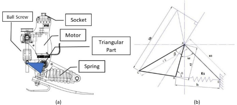
Figure 1(a) shows a prosthetic ankle joint with a motor connected to the ball screw with a belt and pulley mechanism. The mathematical model will be developed using reference torque and ankle angle as input and the required angle ω, which defines the orientation of the central triangular part with some reference and can be subsequently used to calculate the required motor angle, will be the output of the model. The angle ω will be calculated to match the reference values of torque T and ankle angle ϕ simultaneously. The exact mathematical model is derived initially but it results in an implicit solution for ω. Since the model will be called recursively in the optimization scheme, a model with an explicit solution is preferable in the numerical calculation. The details of the mathematical model with explicit and implicit solutions are given in the following subsections.
Figure 1.
(a) The schematic model of the prosthetic ankle joint is presented with highlighted sections. The actuator is connected with the spring in a series configuration through a ball-screw mechanism. Moreover, the timing-belt pulley system is used to transfer the motion from the actuator to the ball screw. It is worth mentioning here that the spring travel is mainly dependent on the central triangular part as highlighted. (b) The schematic diagram of the triangular part with the assigned parameters is presented. The triangular components r1, r2, and angle β are the major parameters used to lower the peak power requirement. Here x3 represents the fixed length between ankle joint A and spring fixed support D.
Exact formulation
This section discusses the mathematical model of the ankle prosthesis without any approximations.
Using triangle ΔABD as shown in Figure 1(b), the following expression is obtained using cosine law.
| (1) |
| (2) |
The terms l0 and Fs represent the free length of the spring and spring force, respectively. The torque T defines the able-bodied torque profile, generated due to spring force in the powered ankle. The term T is given as
| (3) |
By using sine law,
| (4) |
| (5) |
Equation (3) becomes,
| (6) |
| (7) |
The final relationship between torque T and angle ω is expressed as
| (8) |
To match the able-bodied torque profile, the iterative algorithm is employed due to the implicit equation to compute the angle ω.
Explicit formulation
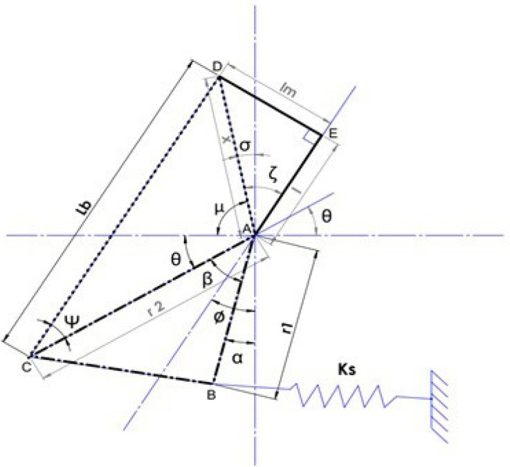
The equation (8) shows the implicit nature of the ω in the exact solution which is not preferable for the optimization process. An explicit solution for omega is preferred and it can be calculated with appropriate assumptions. The spring can be assumed to remain horizontal throughout the stride which is valid for small angles changes in the orientation of the triangular part. As shown in Figure 2, the expression for the torque about the joint A is derived herein. Considering the triangle ΔACD, the following expression is obtained using the cosine law
| (9) |
Figure 2.
As shown in the central triangular part in Figure 1 (a), the schematic diagram of the central triangular part with additional parameters is presented.
The terms Lb and r2 represent the ball screw length and length AC, respectively. The term x can be calculated by applying Pythagoras theorem using triangle ΔADE
| (10) |
To calculate the angle θ, eq. (9) is modified as
| (11) |
Using the triangle ΔACD, the angle Ψ is calculated as
| (12) |
To determine the angle μ, consider the triangle ΔADE in which lm and l represent the length DE and length AE, respectively.
| (13) |
The final expression for the angle μ is represented by employing the human ankle joint angle ϕ as
| (14) |
The α angle can be calculated as
| (15) |
The term β denotes the angle between the length AC and AB. To determine the torque about the ankle joint A, the spring force is calculated as
| (16) |
In eq. (16), Ks and r1 depict the spring constant and length AB, respectively. The final expression is written as
| (17) |
To track the able-bodied angle-torque profile, the ball screw movement is determined by calculating angle α followed by angle θ. Using eq. (16) and (17), the following equation is obtained
| (18) |
Equation (18) is modified to
| (19) |
The angle α can now be calculated by modifying eq. (19) as
| (20) |
The term Tr depicts the reference torque of the ankle joint. For the given reference torque, 31 the angle α can be calculated to mimic the healthy human ankle torque profile. The accuracy of the explicit solution is verified from its comparison with the implicit exact solution. The simulation is performed to analyze the difference between these two derived methods. In terms of motor power calculation, the maximum difference between the results is 0.03616 W which is negligible as compared to 160 W for an 80 kg person. Since the difference between the exact and explicit method is negligible, throughout the study, the explicit method is employed due to its less computational complexity.
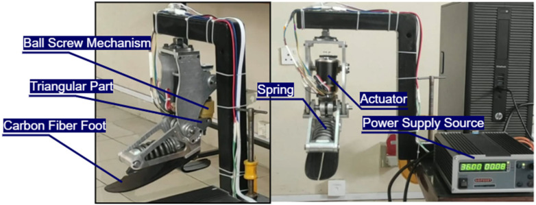
Although the hardware setup is beyond the scope of the presented research, the prototype prosthetic ankle joint conferring to the optimized design parameters is currently being developed, as shown in Figure 3. The materials used are aluminum alloy 7075 & 6061 and Steel ASTM A36, whereas the material used for spring is Music Wire ASTM A228. The BLDC Maxon EC-I motor is being controlled with Beaglebone board via Maxon controller.
Figure 3.
The experimental setup of a powered ankle prosthetic foot for its evaluation in the lab environment.
Design optimization
To attain the able-bodied torque profile against the instantaneous value of ankle angle ϕ, the ball screw mechanism is attached with the actuator at one end and with the elastic element which attaches at a predetermined angle at the other end through a central triangular part ΔABC as shown in Figure 1(a). The healthy human ankle torque cannot be achieved merely with the elastic element due to insufficient torque at the ankle joint if we followed the ankle’s angle profile. Therefore, an actuation system is required to mimic the healthy human ankle torque during locomotion. As we mentioned in the introduction section, the series-elastic actuator is one of the feasible solutions to mimic the able-bodied angle-torque profile with less powered consumption. Motor power plays an important role in the system’s efficiency. The motor power is the product of the required motor velocity and motor torque. Either motor velocity or motor torque should be reduced to improve the power flow within the system. For the prosthetic ankle joint, the spring is stretched between 30% and 50% of the gait cycle. After that, the stretched spring returned to its original position to generate the torque at the ankle joint. In other words, the elastic element stored energy during the terminal stance and released it during the push-off phase. The energy stored in the spring is dependent on the parameters of the triangle ΔABC, including spring-free length, stiffness, and type of the spring. As well as the mounting position and orientation of the spring in the system. In explicit formulation, the spring is assumed to remain in a horizontal position for a small range of angles which is a valid assumption. It is already observed that SEA reduced PP and energy requirements as compared with a direct drive system. Thus, the PP can be reduced further by the optimization of the parameters r1, r2, and the angle β. The sequential quadratic programing (SQP) method is employed to minimize the PP requirement. For optimization, the upper and lower bound of design variables are selected based on the design constraints and allowable spring travel range. The pseudo-code of the algorithm for optimization of ankle prosthesis to reduce peak power requirement is presented in Table 1. Moreover, the objective function f and the constraints g can be expressed as
Table 1.
Pseudocode for optimization of the triangular part to reduce the peak power requirement.
| Algorithm’s Description |
|---|
|
Subjected to
| (21) |
Results and discussion
In this research work, the optimized design is tested for multiple walking speeds to effectively validate the proposed results. In this pursuit, the simulation studies of the powered prosthetic ankle joint model as well as the optimization of the design are presented in the following paragraphs.
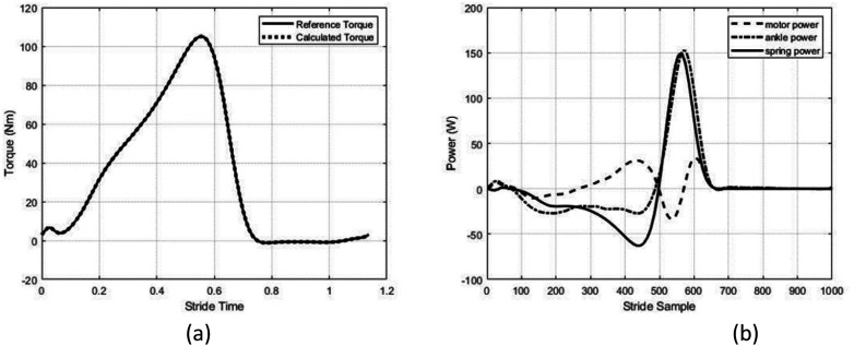
Throughout the simulation study, the simulations are carried out for a subject of 80 kg, and the results are compared with the reference data. 31 The overall data at multiple speeds during walking and running are presented in Table 2. The listed parameters are used for simulation: r1 = 27 mm, r2 = 45 mm, β = 85 deg, Ks = 445 kN/m, lm = 25.4 mm, l = 96.7 mm, and Lb = 109.5 mm. The spring stiffness value is selected from literature. 33 Using eq. (12), the angle α is calculated using the reference torque data followed by the calculation of the ball screw motion profile. By incorporating the ball screw motion profile along with the reference input ϕ, the calculated and reference torque profile perfectly matched as shown in Figure 4(a). In the case of the spring model, which is Music Wire ASTM A228, the maximum energy stored in the spring is limited to 17.4504 J due to spring capacity. Thus, the maximum energy should be under the allowable range. The allowable spring travel to mimic the able-bodied angle and torque profile is 8.856 mm. The simulations were performed for 80 kg person at 1.1 and 1.6 m/s walking speeds. The results are presented and discussed in the following subsections.
Table 2.
Positive and negative work (J/kg) and positive and negative PP (W/kg) at the ankle joint during locomotion.
| Gait | Walking | Running | ||||||||||
|---|---|---|---|---|---|---|---|---|---|---|---|---|
| Speed (m/s) | 0.5 | 1.1 | 1.6 | 2.1 | 2.6 | 0.5 | 1.1 | 1.6 | 2.1 | 2.6 | 3.0 | 4.0 |
| Positive Peak Power | 0.9 | 2.0 | 3.2 | 4.3 | 4.6 | 5.3 | 6.0 | 6.1 | 7.1 | 8.7 | 10 | 14.1 |
| Negative Peak Power | 0.5 | 0.4 | 0.4 | 0.5 | 0.8 | 4.8 | 4.6 | 3.6 | 3.7 | 4.4 | 5.1 | 7 |
| Positive Work | 0.12 | 0.20 | 0.29 | 0.45 | 0.54 | 0.54 | 0.6 | 0.6 | 0.64 | 0.70 | 0.8 | 0.98 |
| Negative Work | 0.14 | 0.13 | 0.07 | 0.04 | 0.05 | 0.48 | 0.42 | 0.31 | 0.27 | 0.29 | 0.32 | 0.39 |
Figure 4.
(a) The reference torque (solid line) represents the healthy human ankle torque. While the dotted line depicts the torque calculated from the derived model. (b) The motor power (dashed line) represents the power delivered and received by the motor during a gait cycle. The ankle power (dash-dot line) shows the healthy human ankle power which needs to be eclipsed. The spring power (solid-line) depicts the instantaneous power generated in the spring. Overall, the graph shows the power flow at 1.1 m/s walking during locomotion.
At 1.1 m/s walking
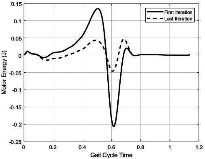
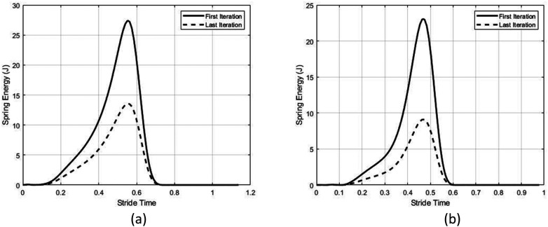
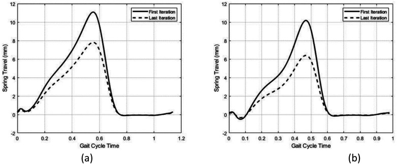
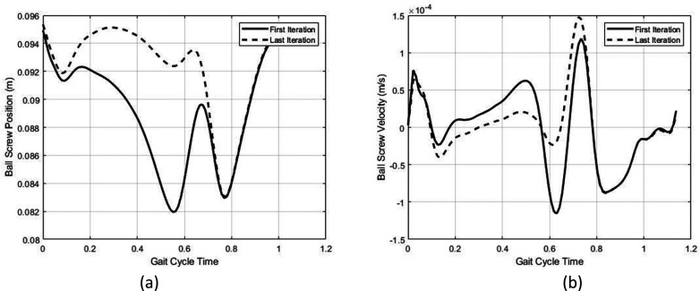
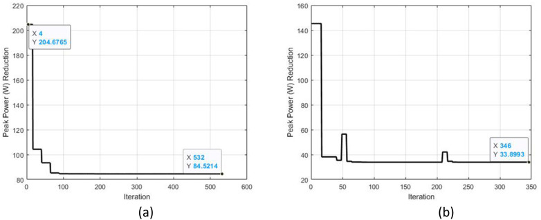
The value of the design variables for optimization are initialized as r1 = 24 mm, r2 = 45 mm, and β = 92 deg. The MATLAB function fmincon is used for optimization using the SQP method. At the first iteration of the optimization, the PP and maximum energy stored in spring are 150.0821 W and 27.34 J, respectively. In the case of a direct drive prosthetic ankle joint, the positive peak power is 160 W at 1.1 m/s walking as represented in Table 2. At the first iteration of optimization, the spring extension is reached up to 11.088 mm which is outside of the safe range. At optimized design variables, the PP value is reduced to 33.8974 W which is almost a 79% reduction at 1.1 m/s walking. Also, the energy stored and released in the motor at optimized design variables is significantly reduced as shown in Figure 5. The maximum energy stored in the spring before the push-off phase is reduced to 13.53 J at optimized design variables as shown in Figure 6(a). Moreover, the spring travel is reduced to 7.91 mm as shown in Figure 7(a). The corresponding ball screw motion profile at the first and last iteration is shown in Figure 8. The optimized design variables at 1.1 m/s walking are r1 = 31.2 mm, r2 = 45.1 mm, and β = 91.74 deg. The optimization curve is represented as shown in Figure 9(b). The motor power, spring power, and ankle power flow at optimized variables are represented as shown in Figure 4(b). At optimized design variables, most of the power required to mimic the able-bodied ankle profile is provided by the spring instead of a motor as shown in Figure 4(b).
Figure 5.
At un-optimized design variables, the motor energy flow is higher than the energy profile at optimized design variables at 1.1 m/s walking.
Figure 6.
(a) The maximum limits of the energy stored in the given spring are less than the energy stored at unoptimized design variables at 1.1 m/s walking. At optimized design variables, the energy storage is lowered to safe limits. (b) The energy storage and release profile at the first and last iteration of the optimization in the spring at 1.6 m/s walking.
Figure 7.
(a) during the push-off phase, the maximum spring stretch at 1.1 m/s walking was reduced to 7.9 mm at optimized design variables from 11.1 mm. (b) Spring travel profile at optimized and un-optimized design variables at 1.6 m/s walking.
Figure 8.
(a) By inspecting the first and last iteration of the optimization, the ball screw position is less varied in the first half gait cycle at optimized design variables as compared to un-optimized design variables. This study is conducted at 1.1 m/s walking. (b) At the first half gait cycle, the magnitude of the ball-screw velocity at 1.1 m/s walking is less as compared to the initially chosen design variables.
Figure 9.
(a) At un-optimized design variables, the peak power stays at around 204 W. After 530 iterations, the peak power is reduced to 84.52 W at 1.6 m/s walking. (b) Optimization curve at 1.1 m/s walking.
At 1.6 m/s walking
The design variables are initialized as r1 = 28 mm, r2 = 52 mm, and β = 88 deg. At the first iteration of optimization, the PP and maximum energy stored in spring are 204.67 W and 23.0317 J, respectively. In the case of a direct drive prosthetic ankle joint, the required PP is 256 W at 1.6 m/s walking. It is noted that the maximum energy stored in the spring surpassed the safe range. The spring travel is calculated to be about 10.173 mm which is again crossed the allowable safe range. The peak power value is reduced to 84.5214 W which amounted to a 66.98% reduction at optimized design variables. The maximum energy stored in the spring is reduced to safe limits from 23.0317 J to 9.09 J as shown in Figure 6(b). Moreover, the spring travel is lowered to 6.39 mm as represented in Figure 7(b). The optimized design variables are r1 = 42 mm, r2 = 60 mm, and β = 82 deg. The optimization curve is shown in Figure 9(a). Furthermore, the power flow in the powered prosthetic ankle joint during locomotion at optimized design variables where negative motor power indicates the power flow towards the motor which can be utilized if the motor-controller has a regenerative capability.
Conclusion
This work optimized the triangular part of the prosthetic ankle joint to reduce the peak power requirements with the help of both the exact and explicit kinematic models. It has been observed that the fine tweaks in the triangular part dimensions significantly reduced the motor peak power as well as maximized the value of the spring energy. The solution space of design variables is selected based on the design constraints. As a result of optimization, the peak power value is reduced up to 78.8% compared with the direct drive system at 1.1 m/s walking speed, while a reduction of 66.98% is observed at 1.6 m/s walking speed. Moreover, the optimization reduced the spring travel range to its safe limits as well as kept the spring energy storage limits within the allowable range. Overall, the amputee potentially can take more steps having the same metabolic cost with the optimized prosthetic ankle joint.
Currently, the control architecture is being designed followed by implementation on the prosthetic ankle joint. The finalized prosthetic ankle joint will be installed on the below-knee amputee for its evaluation in the lab environment for the clinical trials. Moreover, the regenerative motor controller will be employed to utilize the negative power to recharge the battery during locomotion.
Footnotes
The author(s) declared no potential conflicts of interest with respect to the research, authorship, and/or publication of this article.
Funding: The author(s) received no financial support for the research, authorship, and/or publication of this article.
ORCID iD: Muhammad Bilal https://orcid.org/0000-0002-4261-7645
References
- 1.Ziegler-Graham K, MacKenzie EJ, Ephraim PL, et al. Estimating the prevalence of limb loss in the United States: 2005 to 2050. Arch Phys Med Rehabil 2008; 89: 422–429. [DOI] [PubMed] [Google Scholar]
- 2.Kyberd PJ, Hill W. Survey of upper limb prosthesis users in Sweden, the United Kingdom and Canada. Prosthet Orthot Int 2011; 35: 234–241. [DOI] [PubMed] [Google Scholar]
- 3.Maqbool HF, Husman MAB, Awad MI, et al. A real-time gait event detection for lower limb prosthesis control and evaluation. IEEE Trans Neural Syst Rehabil Eng 2017; 25: 1500–1509. [DOI] [PubMed] [Google Scholar]
- 4.Kumar PK, Charan M, Kanagaraj S. Trends and challenges in lower limb prosthesis. IEEE Potentials 2017; 36: 19–23. [Google Scholar]
- 5.Cordella F, Ciancio AL, Sacchetti R, et al. Literature review on needs of upper limb prosthesis users. Front Neurosci 2016; 10: 209. [DOI] [PMC free article] [PubMed] [Google Scholar]
- 6.Asif M, Tiwana MI, Khan US, et al. Advancements, trends and future prospects of lower limb prosthesis. IEEE Access 2021; 9: 85956–85977. [Google Scholar]
- 7.Colborne GR, Naumann S, Longmuir PE, et al. Analysis of mechanical and metabolic factors in the gait of congenital below knee amputees. A comparison of the SACH and Seattle feet. Am J Phys Med Rehabil 1992; 71: 272–278. [DOI] [PubMed] [Google Scholar]
- 8.Winter DA, Sienko SE. Biomechanics of below-knee amputee gait. J Biomech 1988; 21: 361–367. [DOI] [PubMed] [Google Scholar]
- 9.Holgate R, Sugar T, Nash A, et al. A passive ankle-foot prosthesis with energy return to mimic able-bodied gait. In: Proceedings of the ASME design engineering technical conference. 2017, pp.1–8. [Google Scholar]
- 10.Fite KB. Overview of the components used in active and passive lower-limb prosthetic devices. In: Tepe V, Peterson CM. (eds) Full stride: advancing the state of the art in lower extremity gait systems. New York, NY: Springer New York, 2017, pp.55–74. [Google Scholar]
- 11.Shepherd MK, Rouse EJ. Design of a quasi-passive ankle-foot prosthesis with biomimetic, variable stiffness. In: Proceedings - IEEE international conference on robotics and automation. IEEE, 2017, pp.6672–6678. [Google Scholar]
- 12.Shepherd MK, Rouse EJ. The VSPA foot: a quasi-passive ankle-foot prosthesis with continuously variable stiffness. IEEE Trans Neural Syst Rehabil Eng 2017; 25: 2375–2386. [DOI] [PubMed] [Google Scholar]
- 13.Gitter A, Czerniecki JM, DeGroot DM. Biomechanical analysis of the influence of prosthetic feet on below-knee amputee walking. Am J Phys Med Rehabil 1991; 70: 142–148. [DOI] [PubMed] [Google Scholar]
- 14.Czerniecki JM, Gitter A, Munro C. Joint moment and muscle power output characteristics of below knee amputees during running: the influence of energy storing prosthetic feet. J Biomech, 24. Epub ahead of print 1991. DOI: 10.1016/0021-9290(91)90327-J. [DOI] [PubMed] [Google Scholar]
- 15.Ferris AE, Aldridge JM, Rábago CA, et al. Evaluation of a powered ankle-foot prosthetic system during walking. Arch Phys Med Rehabil 2012; 93: 1911–1918. [DOI] [PubMed] [Google Scholar]
- 16.Molen NH. Energy/speed relation of below-knee amputees walking on a motor-driven treadmill. Int Zeitschrift für Angew Physiol Einschließlich Arbeitsphysiologie 1973; 31: 173–185. [DOI] [PubMed] [Google Scholar]
- 17.Palmer ML. Sagittal plane charactrization of normal human ankle function across a range of walking gait speeds, https://dspace.mit.edu/handle/1721.1/16802 (2002, accessed 17 September 2021).
- 18.Hansen AH, Childress DS, Miff SC, et al. The human ankle during walking: implications for design of biomimetic ankle prostheses. J Biomech 2004; 37: 1467–1474. [DOI] [PubMed] [Google Scholar]
- 19.Hitt JK, Sugar TG, Holgate M, et al. An active foot-ankle prosthesis with biomechanical energy regeneration. J Med Devices, Trans ASME, 4. Epub ahead of print 2010. DOI: 10.1115/1.4001139. [DOI] [Google Scholar]
- 20.Zhu J, Wang Q, Wang L. PANTOE 1: Biomechanical design of powered ankle-foot prosthesis with compliant joints and segmented foot. In: IEEE/ASME international conference on advanced intelligent mechatronics, AIM. IEEE, 2010, pp.31–36. [Google Scholar]
- 21.Sup F, Varol HA, Mitchell J, et al. Self-contained powered knee and ankle prosthesis: Initial evaluation on a transfemoral amputee. In: 2009 IEEE international conference on rehabilitation robotics, ICORR. IEEE, 2009, pp.638–644. [DOI] [PMC free article] [PubMed] [Google Scholar]
- 22.Suzuki R, Sawada T, Kobayashi N, et al. Control method for powered ankle prosthesis via internal model control design. In: 2011 IEEE international conference on mechatronics and automation, ICMA. IEEE, 2011, pp.237–242. [Google Scholar]
- 23.Herr HM, Grabowski AM. Bionic ankle-foot prosthesis normalizes walking gait for persons with leg amputation. Proc R Soc B Biol Sci 2012; 279: 457–464. [DOI] [PMC free article] [PubMed] [Google Scholar]
- 24.Cherelle P, Matthys A, Grosu V, et al. The AMP-Foot 2.0: a powered transtibial prosthesis that mimics intact ankle behavior. meca.rma.ac.be, http://citeseerx.istpsu.edu/viewdoc/download?doi=10.1.1.381.5854&rep=rep1&type=pdf (2010, accessed 3 September 2021).
- 25.Versluys R, Lenaerts G, Van Damme M, et al. Successful preliminary walking experiments on a transtibial amputee fitted with a powered prosthesis. Prosthet Orthot Int 2009; 33: 368–377. [DOI] [PubMed] [Google Scholar]
- 26.Ossur. PROPRIO FOOT® — Because the world isn’t flat. Ossur.com. Össur , https://www.ossur.com/en-us/prosthetics/feet/proprio-foot#specificationContentAnchor (2012, accessed 10 January 2022).
- 27.Grimmer M, Eslamy M, Gliech S, et al. A comparison of parallel- and series elastic elements in an actuator for mimicking human ankle joint in walking and running. In: Proceedings - IEEE international conference on robotics and automation. IEEE, 2012, pp.2463–2470. [Google Scholar]
- 28.Grimmer M, Eslamy M, Seyfarth A. Energetic and peak power advantages of series elastic actuators in an actuated prosthetic leg for walking and running. Actuators 2014; 3: 1–19. [Google Scholar]
- 29.Liu J, Osman NAA, Al KM, et al. Optimization and comparison of typical elastic actuators in powered ankle-foot prosthesis. Int J Control Autom Syst 2022; 20: 232–242. [Google Scholar]
- 30.Lee C, Kwak S, Kwak J, et al. Generalization of series elastic actuator configurations and dynamic behavior comparison. Actuators 2017; 6: 1–26. [Google Scholar]
- 31.Grimmer M, Seyfarth A. Mimicking human-like leg function in prosthetic limbs , pp. 105–155. (2014).
- 32.Eslamy M, Grimmer M, Seyfarth A. Effects of unidirectional parallel springs on required peak power and energy in powered prosthetic ankles: Comparison between different active actuation concepts. In: 2012 IEEE international conference on robotics and biomimetics, ROBIO 2012 - conference digest. IEEE, 2012, pp.2406–2412. [Google Scholar]
- 33.Grimmer M, Holgate M, Holgate R, et al. A powered prosthetic ankle joint for walking and running. Biomed Eng Online 2016; 15: 37–52. [DOI] [PMC free article] [PubMed] [Google Scholar]
- 34.Dong D, Ge W, Liu S, et al. Design and optimization of a powered ankle-foot prosthesis using a geared five-bar spring mechanism. Int J Adv Robot Syst 2017; 14: 1–12. [Google Scholar]
- 35.Morrison T, Trainor D, Su H. Optimization of the compliant drive mechanism for a prosthetic ankle. Proc ASME Des Eng Tech Conf, 10. Epub ahead of print 2020. DOI: 10.1115/DETC2020-22442. [DOI] [Google Scholar]
- 36.Au SK, Dilworth P, Herr H. An ankle-foot emulation system for the study of human walking biomechanics. In: Proceedings - IEEE international conference on robotics and automation. IEEE, 2006, pp.2939–2945. [Google Scholar]
- 37.Gates DH. Characterizing ankle function during stair ascent, descent, and level walking for ankle prosthesis and orthosis design. Boston: Boston University Boston, 2004. [Google Scholar]


