Abstract
Objective
To evaluate the following null hypothesis the skeletal and dentoalveolar expansion patterns in the coronal and axial planes are not different with two different types of microimplant-assisted rapid palatal expansion (MARPE) systems.
Methods
Pretreatment (T0) and post-MARPE (T1) cone-beam computed tomography (CBCT) images of 32 patients (14 males and 18 females; mean age, 19.37) were analyzed. We compared two different MARPE systems. One MARPE system included the maxillary first premolars, maxillary first molars, and four microimplants as anchors (U46 type, n = 16), while the other included only the maxillary first molars and microimplants as anchors (U6 type, n = 16).
Results
In the molar region of the U6 and U46 groups, the transverse expansion at the midnasal, basal, alveolar, and dental levels was 2.64, 3.52, 4.46, and 6.32 mm and 2.17, 2.56, 2.73, and 5.71 mm, respectively. A significant difference was observed in the posterior alveolar-level expansion (p = 0.036) and posterior basal-bone-level expansion (p = 0.043) between the groups, with greater posterior skeletal and alveolar expansion in the U6 group.
Conclusions
Compared with the U46 group, the U6 group showed greater posterior expansion at the alveolar and basal-bone levels, with an almost parallel split. Both groups showed a pyramidal expansion pattern in the coronal view.
Keywords: Microimplant-assisted rapid palatal expansion, Maxillary transverse discrepancy, Cone-beam computed tomography, Bicortical engagement
INTRODUCTION
Rapid palatal expansion (RPE) is a treatment modality for patients with transverse discrepancies that have a prevalence of 8–23%, with an average of approximately 10% in adults.1 However, Proffit and White2 reported that 30% of adults had a transverse discrepancy. RPE enables maxillary skeletal expansion by separating the midpalatal suture and is used to treat bilateral or unilateral buccal crossbites. RPE is indicated until adolescence for growing patients with mixed dentition.3 However, for young adults and adolescents, who present skeletal maturity after growth-spurt completion, nonsurgical RPE can cause well-known side effects, including buccal tipping of the anchor teeth, loss of buccal alveolar bone height, detrimental periodontal consequences, and lack of long-term stability.4-7 The skeletal expansion in RPE is obtained by overcoming the resistance from the zygomatic buttress and separation of the circum-maxillary sutures, such as the midpalatal and pterygopalatine sutures.7,8 With increased age, these sutures are difficult to disarticulate due to increased bone density and interdigitation. Therefore, in adults with maxillary constriction, surgically assisted RPE (SARPE) or microimplant-assisted RPE (MARPE), that uses various temporary anchorage devices, is recommended.4,9 Although SARPE can surgically resolve maxillary constriction, it is limited by cost, time, and morbidity due to surgery. Moreover, according to a recent study, a more parallel expansion pattern in the palate and basal bone was observed in the MARPE group compared with that in the SARPE group in the coronal and axial planes.4
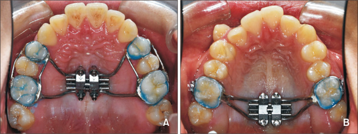
MARPE utilizes four palatal microimplants combined with a palatal expander, and either the maxillary first premolars and molars (U46 type) or only the maxillary first molars (U6 type), for appliance anchorage. The two types of MARPE use different microimplant sites based on the position of the jackscrew (anterior and posterior) (Figure 1). The U6 type includes a posterior jackscrew and microimplants, while the U46 type includes an anterior jackscrew and microimplants between the maxillary first premolars and first molars.1 Despite several studies on coronal and axial expansion using MARPEs, data comparing orthodontic outcomes of two different types of MARPE are lacking.1,10-13
Figure 1.
MARPE appliances. A, U46 type (MSE-12; Biomaterials, Seoul, Korea). B, U6 type (MSE-12; Biomaterials).
MARPE, microimplant-assisted rapid palatal expansion.
Cone-beam computed tomography (CBCT) allows imaging at relatively low radiation dosages and shows the skeletal and dentoalveolar structures with minimal image distortion.14-17 Unlike two-dimensional radiographs, CBCT clarifies the angular and linear movements of each tooth and three-dimensional (3D) changes in the maxillofacial complex after maxillary expansion.18 Lim et al.19 reported the stability of the skeletal, alveolar, and dental changes using the hybrid hyrax expander (which is similar to the U46 type in this study) using CBCT, and de Oliveira et al.4 evaluated the skeletal and dentoalveolar changes with maxillary skeletal expanders (MSEs), (which is similar to the U6 type in this study) using CBCT.20
This study aimed to compare the expansion amounts and patterns of two different types of MARPE systems (U6 and U46) in the axial (anterior and posterior) and coronal planes (skeletal, alveolar, and dental) using pre- and post-expansion CBCT images. Our null hypothesis was that the skeletal and dentoalveolar expansion patterns in the coronal and axial planes are not different with two different types of MARPE systems (U6 and U46).
MATERIALS AND METHODS
This clinical study was approved by the Institutional Review Board of the Dankook University Dental Hospital (DKUDH IRB 2021-9-003).
Participants
This retrospective study enrolled 36 patients diagnosed with a transverse discrepancy, since April 2005 at the Department of Orthodontics, College of Dentistry, Dankook University, Korea. Patients who met the inclusion criteria were recruited consecutively, and out of 36 patients, four failed to exhibit opening of the midpalatal suture, indicating a mean maxillary expansion success rate of 88.9%. Finally, this study included 32 patients (14 males and 18 females) with a mean age of 19.37 years (minimum, 12 years; maximum, 29 years).
Participants were selected according to the following inclusion criteria: 1) age > 12 years; 2) Available CBCT images taken before maxillary expansion (T0) and after a 3-month retention period following maxillary expansion (T1); 3) No history of general diseases or congenital cranial malformations; 4) Midpalatal suture split after maxillary expansion observed on post-MARPE CBCT images (T1); 5) No impacted maxillary first premolars and maxillary first molars; and 6) No history of orthodontic treatment.
Treatment protocol
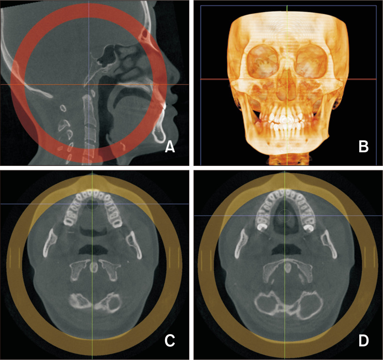
In this study, we compared two types of tooth- and bone-borne MARPEs. One type included the maxillary first premolars, maxillary first molars, and four microimplants as anchors (U46 group, n = 16), and the other included only the maxillary first molars and microimplants as anchors (U6 group, n = 16) (Figure 1). Before using MARPE, the palatal bone depth was measured on the T0 CBCT images after orientation (Figure 2) for distinguishing the bony cortices of the palate and nasal floor.21 The microimplant length was selected based on the measured depth. The MARPE (MSE-12, type I; 0.8 mm expansion in 4 turns [1 revolution]; Biomaterials, Seoul, Korea) device made passive contact with the underlying tissue and was soldered to four bands in the U46 group and two bands in the U6 group. After cementation of the device on the maxillary first premolars and molars (U46 type) or the maxillary first molars (U6 type), four titanium microimplants (OAS-T1511 1.5 mm × 11 mm, OSA-T1513 1.5 mm × 13 mm; Biomaterials) were installed in the slots of the device.22
Figure 2.
Re-orientation A, Sagittal view: palatal plane is parallel to the axial plane. B, Coronal view: 3D image, the line joining the lower margins of the orbits is parallel to the axial plane. C, D, Axial view: Lines passing through the palatal root canals of the bilateral maxillary first premolars (C) and first molars (D).
The microimplants were installed symmetrically with reference to the midpalatal suture using a contra-angle engine driver for positioning. Subsequently, an MSE ratchet wrench driver was used to install the remaining screw with an insertion torque between 15N and 20N. The activation protocol was 2 turns/day until the prescribed expansion was achieved.4 The amount of expansion was determined based on the Yonsei Transverse Index (YTI), which is the distance difference between the furcations of the maxillary and mandibular first molars. Patients were followed-up weekly or fortnightly until YTI reached the normal range (YTI in normal occlusion, –0.39 ± 1.87 mm).23
Measurements
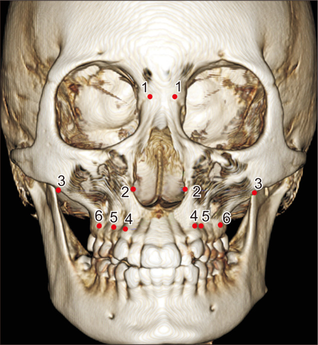
CBCT images were acquired in C-mode (full skull mode) for 17 seconds, with a voxel size of 0.39 mm, using a CT scanner (Alphard VEGA; ASAHI Roentgen IND, Kyoto, Japan) set at 6.0 mA and 80 kV. Patients were asked to sit upright with the Frankfort horizontal plane parallel to the floor. The images were imported as DICOM files using the 3D imaging software InVivo5® (Anatomage, San Jose, CA, USA), and all measurements were performed. Image reorientation was performed with the lower margin of the orbit parallel to the axial plane in the coronal view, and the palatal plane parallel to the axial plane in the sagittal view, as shown in Figure 2. Maxillary expansion at the alveolar level was evaluated based on a previous study by Magnusson et al.24 using the Ectocanine, Ectopremolare, and Ectomolare which are the most inferolateral points on the alveolar ridge at the center of the bilateral maxillary canines, maxillary first premolars, and maxillary first molars, respectively (Figure 3).
Figure 3.
Landmarks used in this study. 1, The most lateral point of the nasofrontal suture. 2, The most lateral point of the nasal cavity. 3, The most inferolateral point of the zygomaticomaxillary suture. 4, Ectocanine, the most inferolateral point on the alveolar ridge at the center of the maxillary canine. 5, Ectopremolare, the most inferolateral point on the alveolar ridge at the center of the maxillary first premolar. 6, Ectomolare, the most inferolateral point on the alveolar ridge at the center of the maxillary first molar. The measurement definitions are presented in Table 1.
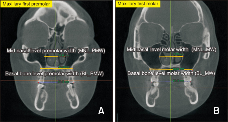
To measure skeletal expansion, the bilateral nasofrontal suture width, nasal cavity width, and zygomaticomaxillary suture distance were measured using a 3D coordinate system for reconstructed images. After reorientation of the 3D images, two coronal slices passing through the palatal root canals of the maxillary first premolars and molars, respectively, were obtained. The distance between the most medial points on the basal bone was measured to determine the basal bone-level premolar and molar widths. The distance between the most lateral points of the nasal cavity was measured to determine the midnasal-level premolar and molar widths (Figure 4).
Figure 4.
Skeletal expansion measurement. A, The distance between the most lateral points of the nasal cavity was measured for the midnasal-level premolar width. The distance between the most medial points on the basal bone at the junction of the lateral wall of the maxillary sinus and the buccal cortex of the maxillary alveolar bone was measured for the basal-bone-level premolar width. B, The distance between the most lateral points of the nasal cavity was measured for the midnasal-level molar width. The distance between the most medial points on the basal bone at the junction of the lateral wall of the maxillary sinus and the buccal cortex of the maxillary alveolar bone was measured for the basal-bone-level molar width.
BL_PMW, basal bone level premolar width; BL_MW, basal bone level molar width; MNL_PMW, midnasal level premolar width; MNL_MW, midnasal level molar width.
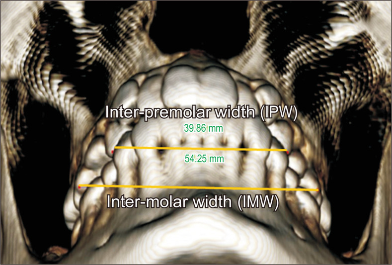
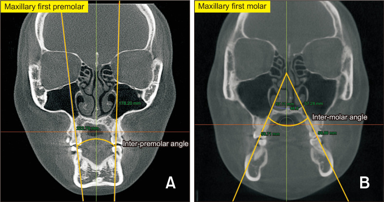
Using a 3D coordinate system, linear dental measurement was performed, including the inter-premolar width and inter-molar width, which represent the distance between the buccal cusp tips of the maxillary first premolars and mesiobuccal cusp tips of the maxillary first molars, respectively (Figure 5). For angular dental measurement, the angle between the lines joining the bilateral fossa and palatal root apices of the maxillary first premolars was measured as the inter-premolar angle (IPA), and the angle between the lines joining the bilateral fossa and palatal root apices of the maxillary first molars was measured as the inter-molar angle (Figure 6). The landmarks and measurements evaluated in this study and their definitions are summarized in Tables 1 and 2 and Figure 3.
Figure 5.
Linear dental measurement. IPW, and IMW were measured using a 3D coordinate system.
3D, three-dimensional; IPW, inter-premolar width; IMW, inter-molar width.
Figure 6.
Dental angular measurement. A, The angle between the lines joining the bilateral fossa and palatal root apices of the maxillary first premolars was measured as the inter-premolar angle. B, The angle between the lines joining the bilateral fossa and palatal root apices of the maxillary first molars was measured as the inter-molar angle.
Table 1.
Definition of skeletal and dental measurements
| Measurement (abbreviation) | Measurement dimension | Description |
|---|---|---|
| Skeletal measurement | ||
| Bilateral nasofrontal suture width (BNSW) | 3D coordinate system | Distance between the most lateral point of the nasofrontal suture point |
| Nasal cavity width (NCW) | 3D coordinate system | Distance between the most lateral point of the nasal cavity |
| Zygomaticomaxillary suture distance (ZD) | 3D coordinate system | Distance between the most infero-lateral point of the zygomaticomaxillary suture |
| Basal bone level premolar width (BL_PMW) | Coronal plane slice | Distance between the most medial point of basal bone at the coronal slice of the premolar region |
| Basal bone level molar width (BL_MW) | Coronal plane slice | Distance between the most medial point of basal bone at the coronal slice of the molar region |
| Midnasal level premolar width (MNL_PMW) | Coronal plane slice | Distance between the most lateral point of the nasal cavity at the coronal slice of the premolar region |
| Midnasal level molar width (MNL_MW) | Coronal plane slice | Distance between the most lateral point of the nasal cavity at the coronal slice of the molar region |
| Alveolar measurement | ||
| Ectocanine width (ECW) | 3D coordinate system | Distance between the most infero-lateral alveolar ridge point of the maxillary canine |
| Ectopremolare width (EPMW) | 3D coordinate system | Distance between the most infero-lateral alveolar ridge point of the maxillary first premolar |
| Ectomolare width (EMW) | 3D coordinate system | Distance between the most infero-lateral alveolar ridge point of the maxillary first molar |
| Dental measurement | ||
| Inter-premolar width (IPW) | 3D coordinate system | Distance between the bilateral buccal cusp of maxillary first molar |
| Inter-molar width (IMW) | 3D coordinate system | Distance between the bilateral mesiobuccal cusp of the maxillary first molar |
| Inter-premolar angle (IPA) | Coronal plane slice | Angle between the fossa-apex (palatal root) line |
| Inter-molar angle (IMA) | Coronal plane slice | Angle between the fossa-apex (palatal root) line |
3D, three-dimensional.
Table 2.
Combination of measurements in Table 1
| Combination of measurement | ||
|---|---|---|
| Amount of expansion | Formula | Description |
| ∆BNSW | ∆BNSW (T1)–∆BNSW (T0) | Amount of bilateral nasofrontal suture width expansion before and after MARPE |
| ∆NCW | ∆NCW (T1)–∆NCW (T0) | Amount of nasal cavity width expansion before and after MARPE |
| ∆ZD | ∆ZD (T1)–∆ZD (T0) | Amount of zygomaticomaxillary suture distance expansion before and after MARPE |
| A_den | IPW (T1)–IPW (T0) | Amount of anterior dental width expansion before and after MARPE |
| P_den | IMW (T1)–IMW (T0) | Amount of posterior dental width expansion before and after MARPE |
| A_alv | EPMW (T1)–EPMW (T0) | Amount of anterior alveolar width expansion before and after MARPE |
| P_alv | EMW (T1)–EMW (T0) | Amount of posterior alveolar width expansion before and after MARPE |
| A_basal | BL_PMW (T1)–BL_PMW (T0) | Amount of anterior basal width expansion before and after MARPE |
| P_basal | BL_MW (T1)–BL_MW (T0) | Amount of posterior basal width expansion before and after MARPE |
| A_mid | MNL_PMW (T1)–MNL_PMW (T0) | Amount of anterior midnasal width expansion before and after MARPE |
| P_mid | MNL_MW (T1)–MNL_MW (T0) | Amount of posterior midnasal width expansion before and after MARPE |
| AP_den | P_den–A_den | Difference in anterior and posterior dental width expansion |
| AP_alv | P_alv–A_alv | Difference in anterior and posterior alveolar width expansion |
| AP_basal | P_basal–A_basal | Difference in anterior and posterior basal width expansion |
| AP_mid | P_mid–A_mid | Difference in anterior and posterior midnasal width expansion |
BNSW, bilateral nasofrontal suture width; NCW, nasal cavity width; ZD, zygomaticomaxillary suture distance; AP_den, difference in anterior and posterior dental width expansion; AP_alv, difference in anterior and posterior alveolar width expansion; AP_basal, difference in anterior and posterior basal width expansion; AP_mid, difference in anterior and posterior midnasal width expansion; IPW, inter-premolar width; IMW, inter-molar width; EPMW, ectopremolare width; EMW, ectomolare width; BL_PMW, basal bone level premolar width; BL_MW, basal bone level molar width; MNL_PMW, midnasal level premolar width; MNL_MW, midnasal level molar width; MARPE, microimplant-assisted rapid palatal expansion.
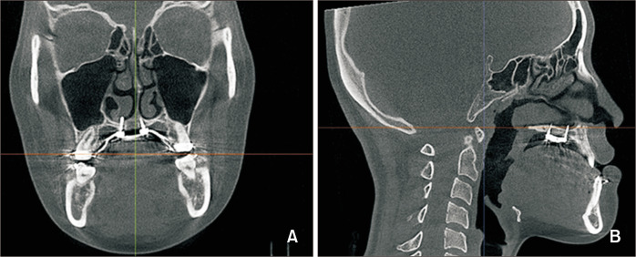
For each type of MARPE, the number of microimplants with bicortical engagement at the palate and nasal floor was evaluated on coronal and sagittal radiographs (Figure 7).
Figure 7.
Bicortical engagement at the palate and nasal floor by microimplants. A, Coronal view. B, Sagittal view.
Statistical analysis
A pilot study was conducted at the beginning of the study. The sample size was calculated using G*power 3.1.9.4 for Windows (Heinrich-Heine-University, Dusseldorf, Germany). A minimum of 12 patients were required in each group to maintain a power of at least 80% with a significance level of 0.05. All data were analyzed using SPSS for Windows ver. 25.0 (IBM Corp., Armonk, NY, USA). All measurements were performed by a single examiner (H.Y.C.). To determine the intra-examiner error, we re-measured 10 samples two weeks after the initial measurement. All intraclass correlation coefficients were > 0.907, indicating high reproducibility.
Normality of the data was tested using the Shapiro–Wilk test, and the Levene test was used to evaluate the homogeneity of distribution. A linear mixed-effects model including age, amount of expansion, and retention period to determine the variables that affect differences between the types of MARPE revealed no confounding factors.
Differences between the U6 and U46 groups were compared using independent t-tests and Mann–Whitney U tests. Paired sample t-tests and Wilcoxon signed-rank tests were used to compare skeletal and dentoalveolar measurements at T0 and T1 within the groups according to the normality of data distribution. Statistical significance was set at p < 0.05.
RESULTS
The mean prescribed expansion and duration of retention were 6.13 ± 2.06 mm (U6 group, 6.66 ± 2.03 mm; U46 group, 5.60 ± 2.00 mm) and 144.0 days (U6 group, 123.81 days; U46 group, 164.19 days), respectively (Table 3). Follow-up CBCT image (T1) were acquired after the retention period.
Table 3.
Comparison of the number of patients, age, Yonsei transverse index value and amount of expansion between the groups
| Variable | U6 type (SD) (n = 16) | U46 type (SD) (n = 16) | p-value |
|---|---|---|---|
| Age (yr) | 19.50 (4.27) | 19.06 (4.73) | 0.696 |
| YTI value (mm) at T0 | −3.45 (0.85) | −2.91 (0.91) | 0.101 |
| Amount of prescribed expansion (mm) | 6.66 (2.03) | 5.60 (2.00) | 0.148 |
| YTI value (mm) at T1 | −0.25 (0.56) | −0.49 (0.56) | 0.250 |
| Duration of retention (day) | 123.81 (59.75) | 164.19 (126.34) | 0.261 |
YTI, Yonsei transverse index; SD, standard deviation; N, number of patients.
At three months after the post-expansion retention period, the midnasal, basal, alveolar, and dental level transverse expansion in the molar region was 2.64, 3.53, 4.46, and 6.33 mm and 2.17, 2.31, 2.73, and 5.65 mm in the U6 and U46 groups, respectively. Posterior alveolar- and basal-bone-level expansion were significantly different between the groups (p = 0.036 and p = 0.043, respectively), with greater posterior skeletal and alveolar expansion in the U6 group (Table 4).
Table 4.
Comparison of the skeletal, alveolar, and dental maxillary expansion between the groups
| Measurement | Landmark | U6 type | U46 type | U6 type vs. U46 type | p-value | ||||||
|---|---|---|---|---|---|---|---|---|---|---|---|
| Mean difference | SD | p-value | Mean difference | SD | p-value | Comparison | |||||
| Skeletal | ∆BNSW | 0.47 | 0.83 | 0.039 | 0.67 | 0.91 | 0.01 | 0.525 | |||
| ∆NCW | 2.68 | 1.97 | < 0.001 | 2.31 | 1.61 | < 0.001 | 0.724a | ||||
| ∆ZD | 3.07 | 1.77 | < 0.001 | 2.68 | 2.16 | < 0.001 | 0.578 | ||||
| A_mid | 2.69 | 1.43 | < 0.001 | 2.14 | 1.35 | < 0.001 | 0.184a | ||||
| P_mid | 2.64 | 1.25 | < 0.001 | 2.17 | 1.11 | < 0.001 | 0.239a | ||||
| A_basal | 2.85 | 1.82 | < 0.001 | 2.56 | 2.02 | < 0.001 | 0.402a | ||||
| P_basal | 3.53 | 2.01 | < 0.001 | 2.31 | 1.43 | < 0.001 | U6 type > U46 type | 0.043a,* | |||
| Alveolar | A_alv | 4.08 | 2.03 | < 0.001 | 4.29 | 1.69 | < 0.001 | 0.745 | |||
| P_alv | 4.46 | 2.23 | < 0.001 | 2.73 | 2.22 | < 0.001 | U6 type > U46 type | 0.036* | |||
| Dental | A_den | 4.77 | 2.22 | < 0.001 | 5.32 | 2.41 | < 0.001 | 0.505 | |||
| P_den | 6.33 | 2.19 | < 0.001 | 5.65 | 2.57 | < 0.001 | 0.428 | ||||
BNSW, bilateral nasofrontal suture width; NCW, nasal cavity width; ZD, zygomaticomaxillary suture distance; SD, standard deviation; N, number of subjects.
aMann–Whitney U test.
*p < 0.05.
The difference in anterior and posterior alveolar (AP_alv) was significantly different between the groups (p < 0.001). Compared with that in the premolar region, AP_alv in the molar region was 0.69 mm greater in the U6 group and 1.56 mm lesser in the U46 group (Table 5).
Table 5.
Anterior and posterior linear differences in expansion between the U6 type and the U46 groups (posterior–anterior)
| Measurement | U6 type | U46 type | p-value | |||
|---|---|---|---|---|---|---|
| Mean | SD | Mean | SD | |||
| AP_den (mm) | 1.58 | 2.47 | 0.33 | 1.99 | 0.138 | |
| AP_alv (mm) | 0.69 | 1.43 | −1.56 | 2.09 | 0.001a,*** | |
| AP_basal (mm) | 0.68 | 0.88 | −0.22 | 1.67 | 0.077 | |
| AP_mid (mm) | −0.05 | 1.09 | 0.04 | 0.96 | 0.818 | |
AP_den, difference in anterior and posterior dental width expansion; AP_alv, difference in anterior and posterior alveolar width expansion; AP_basal, difference in anterior and posterior basal width expansion; AP_mid, difference in anterior and posterior midnasal width expansion; SD, standard deviation.
aMann–Whitney U test.
***p < 0.001.
Compared with that in the premolar region, alveolar-level expansion in the molar region was 109% and 64% in the U6 and U46 groups, respectively. The dental expansion achieved was not significantly different between the groups (Table 4).
Both groups showed pyramidal maxillary expansion in the coronal view; the more superiorly the anatomical structure location from the appliance, the lesser the expansion observed. Compared to those at T0, the bilateral nasofrontal suture width, nasal cavity width, and zygomaticomaxillary suture distance at T1 increased by 0.47, 2.68, and 3.07 mm (p < 0.05) and by 0.67, 2.31, and 2.68 mm (p < 0.05) in the U6 and U46 groups, respectively. None of the above measurements differed significantly between the groups (Table 4).
Regarding angular measurements (T1–T0), IPA in the U6 and U46 types increased by 2.64° and 6.04°, respectively (p = 0.036). The inter-molar angle increased by 7.06° and 5.88°, respectively (p = 0.752) (Table 6).
Table 6.
Anterior and posterior angular difference (°) in expansion between the U6 and the U46 groups (posterior–anterior)
| Measurement | U6 type (SD) | U46 type (SD) | p-value |
|---|---|---|---|
| IPA (T1–T0) | 2.64 (5.88) | 6.04 (5.18) | 0.036* |
| IMA (T1–T0) | 7.06 (5.27) | 5.88 (6.49) | 0.752a |
IPA, inter-premolar angle; IMA, inter-molar angle; T0, pretreatment; T1, after a 3-month retention period following maxillary expansion; SD, standard deviation.
aMann–Whitney U test.
*p < 0.05.
DISCUSSION
In this study, we used CBCT to evaluate post-expansion skeletal and dentoalveolar changes between the U6- and U46-type MARPE. In particular, we focused on the differences in coronal and axial expansion between the groups.
Most previous studies have described the orthopedic effects of RPE and MARPE.25-28 Gunyuz Toklu et al.26 compared the skeletal effects of hybrid expanders (tooth-and-bone supported) with those of traditional tooth-supported expanders, while Altieri and Cassetta28 compared tooth-supported expanders with bone-supported expanders and the latter showed greater increase in the nasal floor width, which is consistent with the results of the present study. In contrast, Lagravère et al.27 found no significant differences in skeletal structures between bone-supported (using two anterior palatal microimplants) and tooth-supported expanders, which is inconsistent with our findings. Unlike previous studies, we compared two types of tooth-and-bone-supported MARPE (U46 and U6 types using four microimplants in different positions) in both the axial and coronal planes. In this study, out of 36 patients, four showed no signs of midpalatal suture split, indicating a 88.9% success rate. Moreover, the number of bicortically engaged microimplants was significantly different between and the groups (Table 7).
Table 7.
Number of bicortically engaged microimplants according to MARPE type
| Measurement | U6 type (SD) | U46 type (SD) | p-value |
|---|---|---|---|
| Number of bicortically engaged microimplants | 3.88 (0.5) | 2.56 (0.96) | 0.001a,*** |
MARPE, microimplant-assisted rapid palatal expansion; SD, standard deviation.
aMann–Whitney U test.
***p < 0.001.
Lione et al.20 used a conventional RPE in growing patients and reported that the midpalatal suture split at the anterior and posterior nasal spines was 3.01 and 1.15 mm, respectively. Thus, the posterior expansion was 40% of that in the anterior region, with a fan-shaped expansion. However, Cantarella et al.7 used an MSE expander and reported that the midpalatal suture split at the posterior nasal spine (4.3 mm) was 90% of that at the anterior nasal spine (4.8 mm). Different biomechanics in MSE using four microimplants, compared to conventional RPE, cause expansion forces closer to the center of resistance of the maxilla, thereby resulting in more skeletal expansion of the maxillary complex.13,29,30 As patients with bilateral or unilateral crossbite in the molar region are more common, most patients with transverse discrepancy need more expansion posteriorly than anteriorly. Recently, Lee et al.21 reported that in MARPE with four bicortically engaged microimplants, the posterior region of the maxilla showed more expansion than the anterior region, with a ratio of 111%. This series of studies shows that in maxillary expansion, skeletal anchorage increases posterior expansion by better overcoming the resistance of anatomical structures such as the midpalatal suture, zygomatic buttress, and pterygopalatine suture.31-33 This study also showed similar results; in the U6 group, alveolar expansion in the maxillary first molar and first premolar regions was 4.46 and 4.08 mm, respectively (Table 4). Moreover, AP_alv was significantly greater indicating greater posterior alveolar expansion than that in the U46 group (p = 0.001) (Table 5). Posterior basal bone expansion was 3.53 mm in the U6 group, indicating greater posterior skeletal expansion than that in the U46 group (2.31 mm) (p = 0.043) (Table 4).
In a previous study on SARPE in a similar age group, parallel expansion in the axial view was obtained upon the release of the pterygoid plates.34 When the pterygoid plates were not released, anterior expansion was greater than the posterior expansion.5,35,36 This means that among the circum-maxillary sutures and structures resisting maxillary expansion, disarticulation of the pterygopalatine suture is the most important factor for successful maxillary expansion. In this study, the number of bicortically engaged microimplants based on the MARPE design (U46 type and U6 type) was one of the main factors for pterygopalatine suture release and maxillary expansion (Table 7).
Lee et al.21 recently reported a significant correlation between the number of microimplants with bicortical engagement and pterygopalatine suture openings. In this study, we observed a significantly greater number of bicortically engaged microimplants in the U6 group (3.88 ± 0.5) than in the U46 group (2.56 ± 0.96) (Table 7), and greater alveolar and skeletal expansion was observed in the U6 group.7,20 Thus, the ability of the U46 type to overcome suture resistance to promote posterior suture split was less than that of the U6 type.
The palatal soft tissue along the midpalatal suture becomes thickest at a point 4 mm behind the incisive papilla.37 Therefore, if MARPEs are placed on the anterior slope of the palate, the depth of the microimplant placed inside the bone is shallower than that placed in the posterior region. Therefore, longer microimplants are needed for bicortical engagement. Our results show that the in the U46 group, the anterior microimplants rarely penetrated the cortical bone of the nasal floor.
Maxillary expansion showed a pyramidal pattern and decreased as the vertical distance from the device increased. The higher the anatomical structure, the smaller the amount of transverse expansion. Skeletal expansion, determined based on the basal and alveolar expansions in the molar region, was greater in the U6 group than in the U46 group (Figure 8).
Figure 8.
Comparison of the skeletal, alveolar, and dental maxillary expansion in the premolar and molar regions between the U6 and the U46 groups.
Factors for efficient maxillary expansion by different types of MARPE include
• Bicortical microimplant engagement is a critical factor for pterygopalatine suture opening and parallel skeletal expansion.21,30,32
• The vertical location of the expansion jackscrews resulted in different expansion patterns. The deeper the palatal vault, the more directly the forces (close to the center of resistance of the maxilla) can be applied to the circummaxillary sutures and basal bone. When microimplants were installed in the deeper palate, the leverage effect was lower in the posterior region than that with conventional RPE.
• MARPEs placed in the posterior region overcome the resistance of the pterygopalatine suture and zygomatic buttress bone well.38 Whereas, when placed on the anterior palatal slope, bicortical engagement is difficult to achieve. Moreover, the stability is lower than with bicortical engagement, in which microimplants resist lateral forces more effectively.32
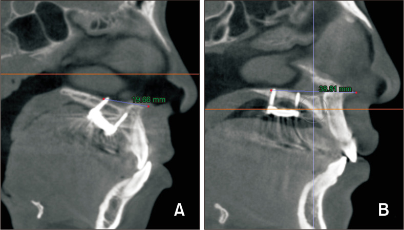
In addition to bicortical engagement, the distance from the posterior microimplant to the anterior nasal spine (ANS) affects MARPE. In this study, the average distance in the U6 and the U46 groups was 38.91 and 29.26 mm, respectively (Figure 9). Future studies should evaluate the post-MARPE difference in multiple planes according to the distance from the palatal microimplant to the ANS.
Figure 9.
A, Distance from the ANS to the posterior microimplant in the U46 group (mean, 29.26 mm), B, distance from the ANS to the posterior microimplant in the U6 group (mean, 38.91 mm).
ANS, anterior nasal spine.
The degree of buccal tipping of the maxillary first molars was higher than that of the premolars in the U6 group. As expected, the angular change in the maxillary first premolars in the U46 group was greater than that in the U6 group (Table 6). The jackscrew exerting lateral forces caused bending of the alveolar bone in the posterior teeth39 and tipping of the anchor teeth.40 de Oliveira et al.4 reported an average buccal inclination of 3.3° in the first molar using MSE. In this study, the changes in inter-molar angles were 7.06° and 5.88° in the U6 and U46 groups, respectively. We observed a slight increase in dental tipping compared with previous studies, and we considered the residual stress of the MARPE during the retention period as a possible cause for the difference. Similar to other studies, the degree of buccal tipping of the maxillary first molars was greater than that of the maxillary first premolars in the U6 group. However, the degree of buccal tipping was similar in the maxillary first premolars and molars in the U46 group.
Based on these results, it was possible to determine the ratios of skeletal, alveolar, and dental expansions. In addition, clinicians can clearly recognize the anteroposterior differences in the dental and skeletal effects at various vertical levels according to the MARPE design and utilize the appliance suitable for each indication.
As a limitation of the present study, additional studies with long-term follow-up and larger samples are needed to accurately evaluate the differences in skeletal (basal-bone and midnasal level) expansion between the groups. Moreover, analysis of the long-term stability of the skeletal expansion effect after different types of MARPE is needed to further our knowledge and help clinicians select the appropriate expansion appliance for their patients.
CONCLUSIONS
The null hypothesis of this study was rejected. The conclusions of this study are as follows.
First, both types of MARPE devices efficiently split the sutures. The U6 group showed greater expansion at the alveolar and basal-bone levels in the posterior region, with an almost parallel split, compared to the U46 group. In contrast, in the U46 group, the midpalatal suture opening was greater anteriorly than posteriorly.
Second, both types of MARPE devices showed a pyramidal pattern of expansion in the coronal view. In the U6 group, basal and alveolar expansions in the molar region were greater than those in the U46 group, indicating greater skeletal expansion.
Funding Statement
FUNDING None to declare.
Footnotes
AUTHOR CONTRIBUTIONS
Conceptualization: HYC, SML. Data curation: HYC. Formal analysis: HYC, SML. Investigation: HYC. Methodology: HYC, SML, JWL. Project administration: HYC, SML, JWL, DHC, MHL. Resources: HYC, SML. Supervision: SML, JWL, DHC, MHL. Validation: HYC. Visualization: HYC. Writing–original draft: HYC, SML. Writing–review & editing: HYC, SML, JWL, DHC, MHL.
CONFLICTS OF INTEREST
No potential conflict of interest relevant to this article was reported.
REFERENCES
- 1.Lee SR, Lee JW, Chung DH, Lee SM. Short-term impact of microimplant-assisted rapid palatal expansion on the nasal soft tissues in adults: a three-dimensional stereophotogrammetry study. Korean J Orthod. 2020;50:75–85. doi: 10.4041/kjod.2020.50.2.75. https://doi.org/10.4041/kjod.2020.50.2.75. [DOI] [PMC free article] [PubMed] [Google Scholar]
- 2.Proffit WR, White RP., Jr Who needs surgical-orthodontic treatment? Int J Adult Orthodon Orthognath Surg. 1990;5:81–9. https://pubmed.ncbi.nlm.nih.gov/2074379/ [PubMed] [Google Scholar]
- 3.Mohan CN, Araujo EA, Oliver DR, Kim KB. Long-term stability of rapid palatal expansion in the mixed dentition vs the permanent dentition. Am J Orthod Dentofacial Orthop. 2016;149:856–62. doi: 10.1016/j.ajodo.2015.11.027. https://doi.org/10.1016/j.ajodo.2015.11.027. [DOI] [PubMed] [Google Scholar]
- 4.de Oliveira CB, Ayub P, Ledra IM, Murata WH, Suzuki SS, Ravelli DB, et al. Microimplant assisted rapid palatal expansion vs surgically assisted rapid palatal expansion for maxillary transverse discrepancy treatment. Am J Orthod Dentofacial Orthop. 2021;159:733–42. doi: 10.1016/j.ajodo.2020.03.024. https://doi.org/10.1016/j.ajodo.2020.03.024. [DOI] [PubMed] [Google Scholar]
- 5.Park JJ, Park YC, Lee KJ, Cha JY, Tahk JH, Choi YJ. Skeletal and dentoalveolar changes after miniscrew-assisted rapid palatal expansion in young adults: a cone-beam computed tomography study. Korean J Orthod. 2017;47:77–86. doi: 10.4041/kjod.2017.47.2.77. https://doi.org/10.4041/kjod.2017.47.2.77. [DOI] [PMC free article] [PubMed] [Google Scholar]
- 6.Gurel HG, Memili B, Erkan M, Sukurica Y. Long-term effects of rapid maxillary expansion followed by fixed appliances. Angle Orthod. 2010;80:5–9. doi: 10.2319/011209-22.1. https://doi.org/10.2319/011209-22.1. [DOI] [PMC free article] [PubMed] [Google Scholar]
- 7.Cantarella D, Dominguez-Mompell R, Mallya SM, Moschik C, Pan HC, Miller J, et al. Changes in the midpalatal and pterygopalatine sutures induced by micro-implant-supported skeletal expander, analyzed with a novel 3D method based on CBCT imaging. Prog Orthod. 2017;18:34. doi: 10.1186/s40510-017-0188-7. https://doi.org/10.1186/s40510-017-0188-7. c0a5028c7c5749d28981e5b6114032c6 [DOI] [PMC free article] [PubMed] [Google Scholar]
- 8.Abate A, Cavagnetto D, Fama A, Matarese M, Lucarelli D, Assandri F. Short term effects of rapid maxillary expansion on breathing function assessed with spirometry: a case-control study. Saudi Dent J. 2021;33:538–45. doi: 10.1016/j.sdentj.2020.09.001. https://doi.org/10.1016/j.sdentj.2020.09.001. [DOI] [PMC free article] [PubMed] [Google Scholar]
- 9.Annarumma F, Posadino M, De Mari A, Drago S, Aghazada H, Gravina GM, et al. Skeletal and dental changes after maxillary expansion with a bone-borne appliance in young and late adolescent patients. Am J Orthod Dentofacial Orthop. 2021;159:e363–75. doi: 10.1016/j.ajodo.2020.11.031. https://doi.org/10.1016/j.ajodo.2020.11.031. [DOI] [PubMed] [Google Scholar]
- 10.Harzer W, Reusser L, Hansen L, Richter R, Nagel T, Tausche E. Minimally invasive rapid palatal expansion with an implant-supported hyrax screw. Biomed Tech (Berl) 2010;55:39–45. doi: 10.1515/bmt.2010.002. https://doi.org/10.1515/bmt.2010.002. [DOI] [PubMed] [Google Scholar]
- 11.Deeb W, Hansen L, Hotan T, Hietschold V, Harzer W, Tausche E. Changes in nasal volume after surgically assisted bone-borne rapid maxillary expansion. Am J Orthod Dentofacial Orthop. 2010;137:782–9. doi: 10.1016/j.ajodo.2009.03.042. https://doi.org/10.1016/j.ajodo.2009.03.042. [DOI] [PubMed] [Google Scholar]
- 12.Garib DG, Navarro R, Francischone CE, Oltramari PV. Rapid maxillary expansion using palatal implants. J Clin Orthod. 2008;42:665–71. https://pubmed.ncbi.nlm.nih.gov/19075382/ [PubMed] [Google Scholar]
- 13.MacGinnis M, Chu H, Youssef G, Wu KW, Machado AW, Moon W. The effects of micro-implant assisted rapid palatal expansion (MARPE) on the nasomaxillary complex--a finite element method (FEM) analysis. Prog Orthod. 2014;15:52. doi: 10.1186/s40510-014-0052-y. https://doi.org/10.1186/s40510-014-0052-y. [DOI] [PMC free article] [PubMed] [Google Scholar]
- 14.De Cock J, Mermuys K, Goubau J, Van Petegem S, Houthoofd B, Casselman JW. Cone-beam computed tomography: a new low dose, high resolution imaging technique of the wrist, presentation of three cases with technique. Skeletal Radiol. 2012;41:93–6. doi: 10.1007/s00256-011-1198-z. https://doi.org/10.1007/s00256-011-1198-z. [DOI] [PubMed] [Google Scholar]
- 15.Mah JK, Danforth RA, Bumann A, Hatcher D. Radiation absorbed in maxillofacial imaging with a new dental computed tomography device. Oral Surg Oral Med Oral Pathol Oral Radiol Endod. 2003;96:508–13. doi: 10.1016/S1079-2104(03)00350-0. https://doi.org/10.1016/s1079-2104(03)00350-0. [DOI] [PubMed] [Google Scholar]
- 16.Abate A, Gaffuri F, Lanteri V, Fama A, Ugolini A, Mannina L, et al. A CBCT based analysis of the correlation between volumetric morphology of the frontal sinuses and the facial growth pattern in caucasian subjects. A cross-sectional study. Head Face Med. 2022;18:4. doi: 10.1186/s13005-022-00308-3. https://doi.org/10.1186/s13005-022-00308-3. 5646d82bd58547428037b43553fdb251 [DOI] [PMC free article] [PubMed] [Google Scholar]
- 17.Farronato M, Maspero C, Abate A, Grippaudo C, Connelly ST, Tartaglia GM. 3D cephalometry on reduced FOV CBCT: skeletal class assessment through AF-BF on Frankfurt plane-validity and reliability through comparison with 2D measurements. Eur Radiol. 2020;30:6295–302. doi: 10.1007/s00330-020-06905-7. https://doi.org/10.1007/s00330-020-06905-7. [DOI] [PubMed] [Google Scholar]
- 18.Timock AM, Cook V, McDonald T, Leo MC, Crowe J, Benninger BL, et al. Accuracy and reliability of buccal bone height and thickness measurements from cone-beam computed tomography imaging. Am J Orthod Dentofacial Orthop. 2011;140:734–44. doi: 10.1016/j.ajodo.2011.06.021. https://doi.org/10.1016/j.ajodo.2011.06.021. [DOI] [PubMed] [Google Scholar]
- 19.Lim HM, Park YC, Lee KJ, Kim KH, Choi YJ. Stability of dental, alveolar, and skeletal changes after miniscrew-assisted rapid palatal expansion. Korean J Orthod. 2017;47:313–22. doi: 10.4041/kjod.2017.47.5.313. https://doi.org/10.4041/kjod.2017.47.5.313. [DOI] [PMC free article] [PubMed] [Google Scholar]
- 20.Lione R, Ballanti F, Franchi L, Baccetti T, Cozza P. Treatment and posttreatment skeletal effects of rapid maxillary expansion studied with low-dose computed tomography in growing subjects. Am J Orthod Dentofacial Orthop. 2008;134:389–92. doi: 10.1016/j.ajodo.2008.05.011. https://doi.org/10.1016/j.ajodo.2008.05.011. [DOI] [PubMed] [Google Scholar]
- 21.Lee DW, Park JH, Moon W, Seo HY, Chae JM. Effects of bicortical anchorage on pterygopalatine suture opening with microimplant-assisted maxillary skeletal expansion. Am J Orthod Dentofacial Orthop. 2021;159:502–11. doi: 10.1016/j.ajodo.2020.02.013. https://doi.org/10.1016/j.ajodo.2020.02.013. [DOI] [PubMed] [Google Scholar]
- 22.Baltatu MS, Tugui CA, Perju MC, Benchea M, Spataru MC, Sandu AV, et al. Biocompatible titanium alloys used in medical applications. Rev Chim. 2019;70:1302–6. doi: 10.37358/RC.19.4.7114. https://doi.org/10.37358/RC.19.4.7114. [DOI] [Google Scholar]
- 23.Koo YJ, Choi SH, Keum BT, Yu HS, Hwang CJ, Melsen B, et al. Maxillomandibular arch width differences at estimated centers of resistance: comparison between normal occlusion and skeletal class III malocclusion. Korean J Orthod. 2017;47:167–75. doi: 10.4041/kjod.2017.47.3.167. https://doi.org/10.4041/kjod.2017.47.3.167. [DOI] [PMC free article] [PubMed] [Google Scholar]
- 24.Magnusson A, Bjerklin K, Kim H, Nilsson P, Marcusson A. Three-dimensional assessment of transverse skeletal changes after surgically assisted rapid maxillary expansion and orthodontic treatment: a prospective computerized tomography study. Am J Orthod Dentofacial Orthop. 2012;142:825–33. doi: 10.1016/j.ajodo.2012.08.015. https://doi.org/10.1016/j.ajodo.2012.08.015. [DOI] [PubMed] [Google Scholar]
- 25.Lin L, Ahn HW, Kim SJ, Moon SC, Kim SH, Nelson G. Tooth-borne vs bone-borne rapid maxillary expanders in late adolescence. Angle Orthod. 2015;85:253–62. doi: 10.2319/030514-156.1. https://doi.org/10.2319/030514-156.1. [DOI] [PMC free article] [PubMed] [Google Scholar]
- 26.Gunyuz Toklu M, Germec-Cakan D, Tozlu M. Periodontal, dentoalveolar, and skeletal effects of tooth-borne and tooth-bone-borne expansion appliances. Am J Orthod Dentofacial Orthop. 2015;148:97–109. doi: 10.1016/j.ajodo.2015.02.022. https://doi.org/10.1016/j.ajodo.2015.02.022. [DOI] [PubMed] [Google Scholar]
- 27.Lagravère MO, Carey J, Heo G, Toogood RW, Major PW. Transverse, vertical, and anteroposterior changes from bone-anchored maxillary expansion vs traditional rapid maxillary expansion: a randomized clinical trial. Am J Orthod Dentofacial Orthop. 2010;137:304.e1–12. discussion 304–5. doi: 10.1016/j.ajodo.2009.09.016. https://doi.org/10.1016/j.ajodo.2009.09.016. [DOI] [PubMed] [Google Scholar]
- 28.Altieri F, Cassetta M. Comparison of changes in skeletal, dentoalveolar, periodontal, and nasal structures after tooth-borne or bone-borne rapid maxillary expansion: a parallel cohort study. Am J Orthod Dentofacial Orthop. 2022;161:e336–44. doi: 10.1016/j.ajodo.2021.11.007. https://doi.org/10.1016/j.ajodo.2021.11.007. [DOI] [PubMed] [Google Scholar]
- 29.Carlson C, Sung J, McComb RW, Machado AW, Moon W. Microimplant-assisted rapid palatal expansion appliance to orthopedically correct transverse maxillary deficiency in an adult. Am J Orthod Dentofacial Orthop. 2016;149:716–28. doi: 10.1016/j.ajodo.2015.04.043. https://doi.org/10.1016/j.ajodo.2015.04.043. [DOI] [PubMed] [Google Scholar]
- 30.Lee RJ, Moon W, Hong C. Effects of monocortical and bicortical mini-implant anchorage on bone-borne palatal expansion using finite element analysis. Am J Orthod Dentofacial Orthop. 2017;151:887–97. doi: 10.1016/j.ajodo.2016.10.025. https://doi.org/10.1016/j.ajodo.2016.10.025. [DOI] [PMC free article] [PubMed] [Google Scholar]
- 31.Tausche E, Hansen L, Hietschold V, Lagravère MO, Harzer W. Three-dimensional evaluation of surgically assisted implant bone-borne rapid maxillary expansion: a pilot study. Am J Orthod Dentofacial Orthop. 2007;131(4 Suppl):S92–9. doi: 10.1016/j.ajodo.2006.07.021. https://doi.org/10.1016/j.ajodo.2006.07.021. [DOI] [PubMed] [Google Scholar]
- 32.Pickard MB, Dechow P, Rossouw PE, Buschang PH. Effects of miniscrew orientation on implant stability and resistance to failure. Am J Orthod Dentofacial Orthop. 2010;137:91–9. doi: 10.1016/j.ajodo.2007.12.034. https://doi.org/10.1016/j.ajodo.2007.12.034. [DOI] [PubMed] [Google Scholar]
- 33.Ghoneima A, Abdel-Fattah E, Hartsfield J, El-Bedwehi A, Kamel A, Kula K. Effects of rapid maxillary expansion on the cranial and circummaxillary sutures. Am J Orthod Dentofacial Orthop. 2011;140:510–9. doi: 10.1016/j.ajodo.2010.10.024. https://doi.org/10.1016/j.ajodo.2010.10.024. [DOI] [PMC free article] [PubMed] [Google Scholar]
- 34.Ramieri GA, Spada MC, Austa M, Bianchi SD, Berrone S. Transverse maxillary distraction with a bone-anchored appliance: dento-periodontal effects and clinical and radiological results. Int J Oral Maxillofac Surg. 2005;34:357–63. doi: 10.1016/j.ijom.2004.10.011. https://doi.org/10.1016/j.ijom.2004.10.011. [DOI] [PubMed] [Google Scholar]
- 35.Asscherickx K, Govaerts E, Aerts J, Vande Vannet B. Maxillary changes with bone-borne surgically assisted rapid palatal expansion: a prospective study. Am J Orthod Dentofacial Orthop. 2016;149:374–83. doi: 10.1016/j.ajodo.2015.08.018. https://doi.org/10.1016/j.ajodo.2015.08.018. [DOI] [PubMed] [Google Scholar]
- 36.Pinto PX, Mommaerts MY, Wreakes G, Jacobs WV. Immediate postexpansion changes following the use of the transpalatal distractor. J Oral Maxillofac Surg. 2001;59:994–1000. discussion 1001. doi: 10.1053/joms.2001.25823. https://doi.org/10.1053/joms.2001.25823. [DOI] [PubMed] [Google Scholar]
- 37.Kim HJ, Yun HS, Park HD, Kim DH, Park YC. Soft-tissue and cortical-bone thickness at orthodontic implant sites. Am J Orthod Dentofacial Orthop. 2006;130:177–82. doi: 10.1016/j.ajodo.2004.12.024. https://doi.org/10.1016/j.ajodo.2004.12.024. [DOI] [PubMed] [Google Scholar]
- 38.Braun S, Bottrel JA, Lee KG, Lunazzi JJ, Legan HL. The biomechanics of rapid maxillary sutural expansion. Am J Orthod Dentofacial Orthop. 2000;118:257–61. doi: 10.1067/mod.2000.108254. https://doi.org/10.1067/mod.2000.108254. [DOI] [PubMed] [Google Scholar]
- 39.Lione R, Franchi L, Cozza P. Does rapid maxillary expansion induce adverse effects in growing subjects? Angle Orthod. 2013;83:172–82. doi: 10.2319/041012-300.1. https://doi.org/10.2319/041012-300.1. [DOI] [PMC free article] [PubMed] [Google Scholar]
- 40.Garrett BJ, Caruso JM, Rungcharassaeng K, Farrage JR, Kim JS, Taylor GD. Skeletal effects to the maxilla after rapid maxillary expansion assessed with cone-beam computed tomography. Am J Orthod Dentofacial Orthop. 2008;134:8–9. doi: 10.1016/j.ajodo.2008.06.004. https://doi.org/10.1016/j.ajodo.2008.06.004. [DOI] [PubMed] [Google Scholar]


