

Significance
Electrolytes with moderate lithium polysulfide (LiPS) solubility are urgently needed to simultaneously mediate the conversion of sulfur (S)/lithium sulfide and suppress LiPS shuttling for achieving practical lithium–sulfur (Li-S) batteries. Here, we show selective fluorination of electrolyte solvents as an effective way to systematically tune solubilities of LiPSs and formulated the single-solvent, single-salt electrolytes with moderate LiPS solubility for high-performance Li-S batteries. The correlation between LiPS solubility, fluorination degree of the electrolyte solvent, and battery performance was systematically investigated. Li-S batteries with optimal LiPSs solubility (~70 mM) exhibited a fivefold increase in cycle life compared with commercial ether-based electrolytes. This work provides a molecular design approach for electrolyte engineering toward high energy density, stable cycling, and long-calendar-life Li-S batteries.
Keywords: Li-S batteries, electrolyte engineering, moderate polysulfide solubility, long calendar life
Abstract
Lithium–sulfur (Li-S) batteries with high energy density and low cost are promising for next-generation energy storage. However, their cycling stability is plagued by the high solubility of lithium polysulfide (LiPS) intermediates, causing fast capacity decay and severe self-discharge. Exploring electrolytes with low LiPS solubility has shown promising results toward addressing these challenges. However, here, we report that electrolytes with moderate LiPS solubility are more effective for simultaneously limiting the shuttling effect and achieving good Li-S reaction kinetics. We explored a range of solubility from 37 to 1,100 mM (based on S atom, [S]) and found that a moderate solubility from 50 to 200 mM [S] performed the best. Using a series of electrolyte solvents with various degrees of fluorination, we formulated the Single-Solvent, Single-Salt, Standard Salt concentration with Moderate LiPSs solubility Electrolytes (termed S6MILE) for Li-S batteries. Among the designed electrolytes, Li-S cells using fluorinated-1,2-diethoxyethane S6MILE (F4DEE-S6MILE) showed the highest capacity of 1,160 mAh g−1 at 0.05 C at room temperature. At 60 °C, fluorinated-1,4-dimethoxybutane S6MILE (F4DMB-S6MILE) gave the highest capacity of 1,526 mAh g−1 at 0.05 C and an average CE of 99.89% for 150 cycles at 0.2 C under lean electrolyte conditions. This is a fivefold increase in cycle life compared with other conventional ether-based electrolytes. Moreover, we observed a long calendar aging life, with a capacity increase/recovery of 4.3% after resting for 30 d using F4DMB-S6MILE. Furthermore, the correlation between LiPS solubility, degree of fluorination of the electrolyte solvent, and battery performance was systematically investigated.
The increasing energy demand in battery markets necessitates the development of next-generation battery systems beyond conventional lithium (Li)-ion batteries (1–4). Among various rechargeable batteries, the lithium–sulfur (Li-S) battery is particularly promising due to its remarkably high specific energy (theoretically 2,600 Wh kg−1, four times higher than that of Li-ion counterpart) and the earth’s abundance of sulfur (S) (3, 5–7). Lithium polysulfides (LiPSs), the soluble intermediates formed during battery cycling, assist the conversion between the insoluble and insulating S and lithium sulfide (Li2S) (8, 9). However, highly soluble LiPSs in the conventional 1,3-dioxolane/1,2-dimethoxyethane (DOL/DME) electrolyte (solubility, ~1,100 mM based on S atom, [S]) (10) diffuse to the anode side and react with Li metal (i.e., notorious LiPS shuttling effect), causing rapid capacity fade, low Coulombic efficiency (CE) (11), and severe self-discharge (12–14). These limitations significantly decrease the cell-level energy density, cycle life, and calendar life, thus hindering practical applications of Li-S batteries.
To address the abovementioned challenges, tremendous efforts have been focused on employing physical and chemical LiPS-trapping strategies in cathodes/separators (15–20). Regulating Li-S conversion pathways to avoid LiPS formation by developing sulfurized polyacrylonitrile (21, 22) and small S molecule (23) cathodes have also attracted extensive attention. However, Li-S cells developed by those strategies often suffer from a high electrolyte-to-S (E/S) ratio (>15 µL mg−1) (15–20) or low S contents (often <60%) (21–23).
Electrolyte design is another important strategy for tuning the LiPS solubility and speciation (24). Major efforts have been focused on studying the electrolytes to access both high and low LiPS solubilities which we summarize and define based on S atom in Fig. 1A, from ultrahigh (>4,000 mM [S]) (10, 25–27), high (4,000 to 200 mM [S]) (8, 10, 28, 29), low (50 to 5 mM [S]) (28, 30–33), to ultralow (<5 mM [S]) (31, 32) solubility of LiPSs (Fig. 1A and SI Appendix, Table S1). However, electrolytes with moderate LiPS solubility (200 to 50 mM [S], green zone in Fig. 1A) have not been explored. We hypothesize that moderate LiPS solubility could be promising since it affords sufficient concentration of polysulfide molecules to mediate the conversion between S and Li2S but is not high enough to cause appreciable LiPS shuttling.
Fig. 1.
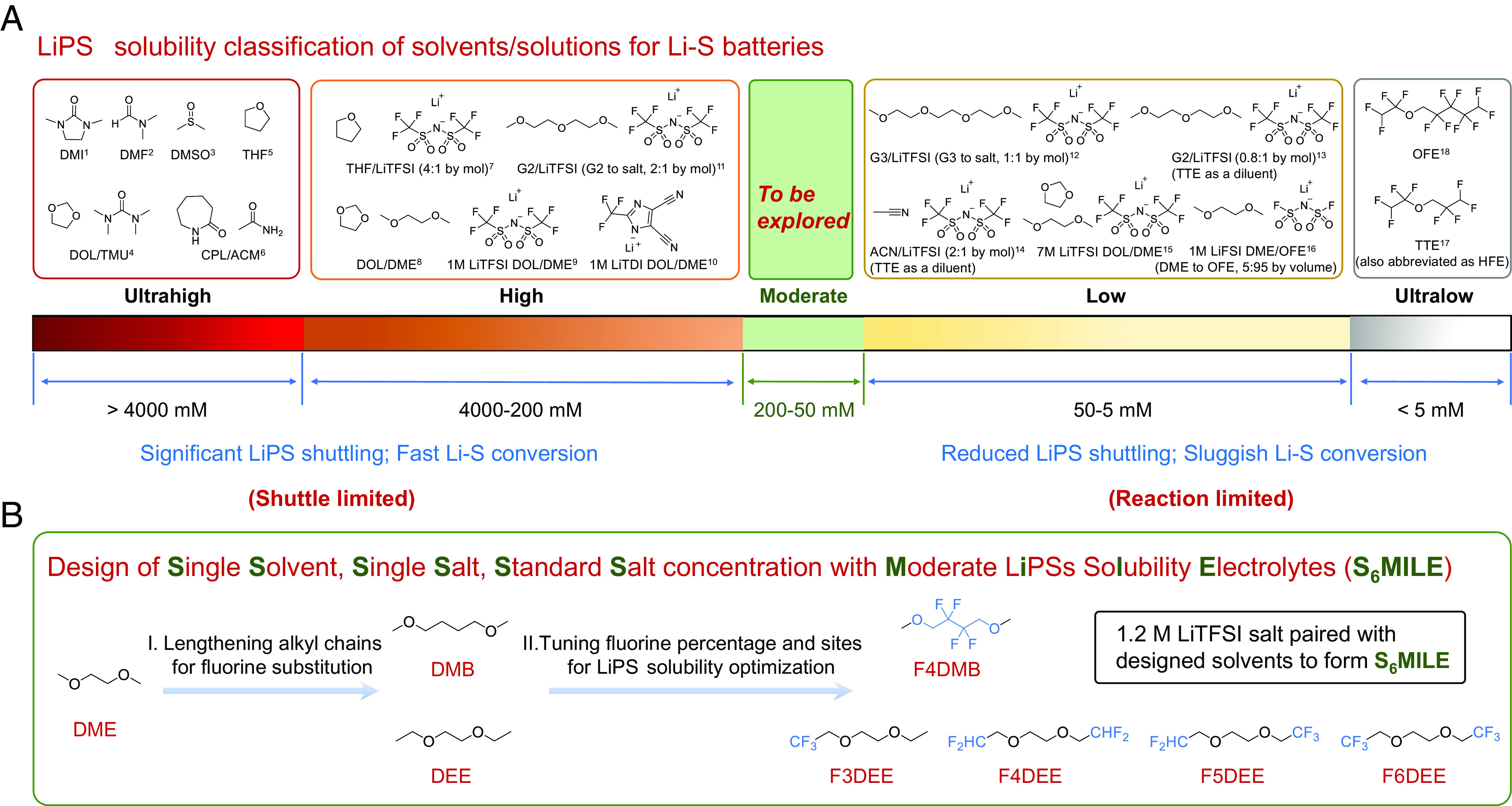
Design concepts of high-performance electrolytes for Li-S batteries. (A) LiPS solubility classification of solvents and solutions for Li-S batteries. Major efforts have been focused on designing the electrolytes with ultrahigh (>4,000 mM, in S atom, [S]), high (4,000 to 200 mM, [S]), low (50 to 5 mM, [S]), and ultralow (<5 mM, [S]) solubility of LiPSs. Electrolytes with moderate LiPS solubility (200 to 50 mM, [S]) are to be explored. See SI Appendix, Table S1 for details. (B) Logical flow for the design of Single-Solvent, Single-Salt, Standard Salt concentration with Moderate LiPS Solubility Electrolytes (S6MILE) for high-performance Li-S batteries.
Electrolytes with ultrahigh LiPS solubility, such as 1,3-dimethyl-2-imidazolidinone (DMI) (26) and dimethyl sulfoxide (10), required less electrolyte solution volume and enabled fast Li-S reaction kinetics. Conventional ether-based electrolytes (e.g., DOL/DME) (8, 34) with high LiPS solubility are widely investigated to optimize the performance of Li-S batteries. However, electrolytes with ultrahigh and high solubility of LiPSs suffered from significant shuttling effect and instability against Li metal anode (10, 26). On the other hand, electrolytes with low LiPS solubility, such as high-concentration electrolytes (HCEs) (28, 30), localized HCEs (LHCEs) (31, 32), and ionic liquid electrolytes (33), mainly focused on lowering the solubility of LiPSs by minimizing the solvent-to-salt ratio. Highly fluorinated solvents with ultralow LiPS solubility are usually needed as diluents in HCEs/LHCEs to decrease the viscosity (28, 31, 32). Although decreasing the LiPS solubility has been shown to be effective in reducing capacity decay from the shuttling effect, low concentration of polysulfides would sacrifice the Li-S conversion kinetics to release full capacity during cycling (35). The solubility of LiPSs in most previously reported sparingly solvating electrolytes was lower than 50 mM [S], leading to sluggish Li-S conversion (requiring elevated operation temperature, ≥55 °C) and low S capacity utilization (24, 28, 32, 36). Moreover, accommodating high concentrations of Li salt requires highly solvating solvents [e.g., acetonitrile (32) and glyme (28, 30, 31, 33)], which tend to be reactive with the Li metal anodes.
Here, we investigated the electrochemical performance of electrolyte solvents with the LiPS solubility from 37 to 1,100 mM [S] and found the solubility of LiPSs in the moderate range from 50 to 200 mM [S] performed the best. Using selective fluorination of electrolyte solvents, we prepared Single-Solvent, Single-Salt, Standard Salt concentration with Moderate LiPS Solubility Electrolytes, namely S6MILE, for Li-S batteries. Specifically, we hypothesize that a series of fluorinated ether molecules (Fig. 1B) as solvents will allow us to systematically correlate their LiPS solubilities with battery performance and further identify an optimal electrolyte solvent molecular design for promoting sufficient reaction kinetics but suppressing the shuttling effect.
We varied the numbers of fluorine (F) atoms on solvent molecules to tune the solubility of LiPSs (LiPS solubility from 37 to 200 mM [S]). Using molecular dynamics (MD) simulations, we systematically investigated the solvation structures and solubility of LiPSs in the rationally designed solvents. The S6MILE were made with 1.2 M lithium bis(trifluoromethanesulfonyl)imide (LiTFSI) as the single salt in the corresponding solvents. By thoroughly evaluating the specific capacity and CE of all the fluorinated ether electrolytes (F3DEE, F4DEE, F4DMB, F5DEE, and F6DEE, shown in Fig. 1B), fluorinated-1,2-diethoxyethane (F4DEE) with the LiPS solubility of 140 mM [S] and fluorinated-1,4-dimethoxybutane (F4DMB) with the LiPS solubility of 70 mM [S] exhibited the optimal LiPS solubility and the best Li-S battery performance at room temperature (RT) and 60 °C, respectively. The Li-S cell using F4DEE-S6MILE showed a high capacity of 1,160 mAh g−1 at 0.05 C at RT. Further, F4DMB-S6MILE based Li-S battery exhibited a high capacity of 1,526 mAh g−1 at 0.05 C at 60 °C and an average CE of 99.89% for 150 cycles at 0.2 C (including 5 activation cycles) under low E/S ratio (5 µL mg−1), which is a fivefold increase in cycle life compared with the conventional DOL/DME electrolyte. Surprisingly, Li-S batteries using the F4DMB-S6MILE exhibited 4.3% capacity increase/recovery after 30 d of calendar aging, while the cells with conventional DOL/DME (even with lithium nitrate additive) suffered from 16% capacity loss. Such an outstanding calendar-aging performance for Li-S batteries has not been observed before. Additionally, our designed molecule has a high boiling point (>150 °C at 1 atm) and can be readily scaled up for industrial applications. We believe that the molecular design to access the moderate LiPS solubility range represents an exciting direction for Li-S batteries.
Results and Discussions
Design Principles of High-Performance Electrolytes for Li-S Batteries.
In Li-S batteries, solid S converts to a group of intermediates, LiPSs (Li2Sx, 2<x<8), upon lithiation. The cell performance is highly related to the solubility of LiPSs in the electrolytes. For electrolytes with ultrahigh/high solubility of LiPSs, such as DMI and DOL/DME, the shuttling effect limits the cell performance (fast capacity decay and low CE) (37). On the contrary, the cell performance using electrolytes with low/ultralow LiPS solubilities is limited by the sluggish Li-S reaction (low capacity utilization and short cycle life) due to the high electron/ion transfer resistance in the solid-solid S-Li2S electrochemistry (35) (SI Appendix, Fig. S1). Therefore, designing the electrolytes with moderate LiPS solubility is crucial to limit the shuttling effect but still enable fast reaction kinetics.
The solubility of LiPSs is related to the solvation ability of Li+ in the electrolytes (38). In conventional ether electrolytes (e.g., DME), Li+ ions are solvated by DME to form a stable five-member ring structure (Li+ clamped by two –O– groups) (39), which enhances the cation–anion separation of LiPSs and thus results in high solubility of LiPSs. To decrease and tune the solubility of LiPSs in the electrolytes, we modified the DME backbone using electron-withdrawing F atoms at the β-position of –O– (Fig. 1B). Specifically, we use longer alkyl spacers in 1,2-diethoxyethane (DEE) and 1,4-dimethoxybutane (DMB), providing sites for tunable F substitution. The modified ethers can maintain their solvation ability when the –F group is further away from –O– groups (40, 41). Selected positions on ether backbones are functionalized with various numbers of F atoms to finely tune the LiPS solvation while simultaneously maintaining the stable cycling with Li metal. By incorporating the electron-withdrawing –CF3 and/or –CHF2 groups into the DEE backbone, four kinds of electrolytes were obtained with different numbers of F atoms ranging from 3 to 6, including F3DEE, F4DEE, F5DEE, and F6DEE (Fig. 1B). Among these molecules, weaker solvation ability was achieved by adding more F atoms in the ether backbone. F4DMB is obtained by incorporating –CF2– groups into DMB (Fig. 1B). Although both F4DEE and F4DMB possess the same numbers of substituted F atoms, the difference in substitution positions resulted in different LiPS solubility as discussed below.
Solubility and Solvation Structure of LiPSs in the Developed Solvents.
To test the solubility of LiPSs, Li2S6 was added into the different solvents to give a nominal concentration of 0.1 M based on Li2S6, and the solutions were rested for 7 d to achieve equilibrium. As shown in Fig. 2A, all the solutions were supersaturated except for the control, DOL/DME (named DD hereafter). From F6DEE to DD (left to right), the solution color became darker, indicating that the concentration of LiPSs in the solvent became higher (30, 31). This qualitative observation confirms our design hypothesis that adding more F atoms in the ether backbones can decrease the dissolution of LiPSs.
Fig. 2.

Experimental and theoretical studies on the lithium polysulfide (Li2S6) solubility and solvation structures in ether and fluorinated ether systems. (A) Photograph of 0.1 M Li2S6 (based on stoichiometric amounts of S8 and Li2S) in different electrolyte solvents. From left to right are F6DEE, F5DEE, F4DMB, F4DEE, F3DEE, DEE, and DD. All the solutions are saturated except for DD. (B) Polysulfide solubility of each electrolyte solvent. The solubility of Li2S6 in the designed solvents (DEE, F3DEE-F6DEE, and F4DMB) is quantified by ICP-OES measurement. The solubility of Li2S6 in DD is adapted from ref. 10. (C) Representative solvation structures of the first Li2S6 solvation sheath and (D) the size distribution of Li2S6 clusters in the DD and designed solvents from classical MD simulations. (E) Frequency of the largest Li2S6 cluster.
The solubility of LiPSs in the solvents was further quantified by inductively coupled plasma optical emission spectrometer (ICP-OES) measurement. The summarized results in Fig. 2B show that the solubility follows the order of DD > DEE > F3DEE > F4DEE > F4DMB > F5DEE > F6DEE in the range of 1,100 to 37 mM [S]. LiPS solubility in DEE is one order of magnitude lower than the conventional DD solvent (10) (~200 versus 1,100 Mm [S]). The solubility of LiPSs further decreased as more F atoms were added, which went from 200 to 37 Mm [S] (from DEE to F6DEE). In contrast, the solubility of LiPSs previously reported for sparingly solvating electrolytes was mostly <50 mM [S] (24, 28). Therefore, the extended moderate range of LiPS solubility achieved by our design provides opportunities to systematically investigate the correlation between the solubility of LiPSs and battery performance, eventually identifying the optimized electrolyte for Li-S batteries.
To provide a better understanding, the solvation structures of LiPSs were further modeled by MD simulations. Selecting Li2S6 as a representative of LiPSs, we calculated the solvation structures of Li2S6 (Fig. 2C) and the distribution of Li2S6 cluster size (Fig. 2D) in DD, DEE, and various fluorinated ether solvents. A higher frequency of larger Li2S6 cluster sizes (e.g., 32- and/or 40-atom clusters) is an indication of poorer solvation ability of LiPSs for the solvent. The frequency of large Li2S6 cluster sizes in the fluorinated ether solvents was found to follow the trend F3DEE < F4DEE < F4DMB < F5DEE (Fig. 2E), matching well with the LiPS solubility trend shown in Fig. 2B.
Correlating LiPS Solubility with Electrochemical Performance of Li-S Batteries.
We paired the designed solvent molecules (DEE, F3DEE, F4DEE, F4DMB, and F5DEE) with 1.2 M LiTFSI salt to formulate single-solvent single-salt electrolytes and tested their electrochemical performance in the Li-S cells. Saturated LiTFSI in F6DEE is used since the solubility of LiTFSI in F6DEE is slightly <1.2 M due to its poor solvation ability. The conventional DD electrolyte is used for the reference. The ionic conductivities measured with separators followed the trend of DD > DEE > F3DEE ≅ F4DEE > F5DEE > F4DMB > F6DEE (SI Appendix, Fig. S2). Fig. 3A shows the voltage profiles of Li-S cells using different electrolytes at a rate of 0.05 C and at RT. The cell using F4DEE with moderate LiPS solubility (140 mM [S]) showed the highest discharge capacity of 1,160 mAh g−1. The cell using DEE (high LiPS solubility, ~200 mM [S]) showed a discharge capacity of 634 mAh g−1, and a charge capacity of 2,001 mAh g−1 (even higher than the theoretical value), indicating severe LiPS shuttling. The F5DEE cell with low LiPS solubility (<50 mM [S]) exhibited a discharge capacity as low as 441 mAh g−1. We further tested cell cycling performance using the DD, DEE, and fluorinated ether electrolytes at RT under flooded conditions (Fig. 3B and SI Appendix, Fig. S3). The Li-S cell capacity follows a nonlinear relation with the LiPS solubility in different solvents (Fig. 3C). This observation contradicts with the previously accepted concept that lowering LiPS solubility results in better cell performance. The cell using F4DEE with moderate LiPS solubility (140 mM [S]) showed the highest average discharge capacity of 651 mAh g−1, accompanied by a high CE of 97.6%. SI Appendix, Fig. S4 shows the normalized discharge capacity of Li-S cells over the course of 50 cycles at RT. Li-S cells using F4DMB and F5DEE electrolytes presented more stable cycling than that of F3DEE and F4DEE electrolytes, indicating that the shuttling effect was significantly reduced due to the decrease of LiPS solubility.
Fig. 3.

Electrochemical performance of Li-S batteries using S6MILE at RT and 60 °C. (A) The voltage profiles of Li-S cells using DD, DEE, and fluorinated ether electrolytes at 0.05 C at RT. (B) Cycling performance of Li-S cells using DD, DEE, and fluorinated ether electrolytes at RT. The cells were first cycled at 0.05 C (2 cycles) and then at 0.1 C (3 cycles), followed by continued cycling at 0.2 C. (C) LiPS solubility–specific capacity relationship plot of different electrolytes at RT. The specific capacity was calculated by averaging the discharge capacity of the first 50 cycles from Fig. 3B. (D) The voltage profiles of Li-S cells using different electrolytes at 0.05 C and at 60 °C. (E) Enlarged first cycle discharge voltage profiles from (D). (F) Typical voltages of the first plateau for solid S conversion to LiPSs (determined at the capacity reaching 15 mAh g−1) and the second plateaus for LiPSs conversion to Li2S (determined at the capacity reaching 900 mAh g−1). (G) Cycling performance of Li-S cells using different fluorinated ether electrolytes (F3DEE-F6DEE and F4DMB) at 60 °C. The conventional DDN electrolyte is used for the reference. DD and DEE electrolytes failed to continuous cycle owing to the shutting effect. (H) LiPS solubility–specific capacity relationship plot of different electrolytes. The specific capacity was calculated by averaging the discharge capacity of the first 50 cycles from Fig. 3G. (I) Average CE of Li-S cells for different electrolytes. The CE was calculated by averaging the CE of the first 50 cycles from SI Appendix, Fig. S6. For all the Li-S cells, the E/S ratio is 15 µL mg−1, and the S content of the cathode is 63%.
We further study the electrochemical performance of Li-S batteries using the designed electrolytes at 60 °C to understand the correlation between LiPS solubility and Li-S cell performance at elevated temperature (Fig. 3 D–I). The cells using DD and DEE (high LiPS solubility, ≥200 mM [S]) showed high initial discharge capacity (>1,200 mAh g−1) at 0.05 C and at 60 °C, but they cannot be charged to the cutoff voltage after the first discharge owing to severe LiPS shuttling (Fig. 3D). By contrast, the F6DEE cell with the lowest LiPS solubility (37 mM [S]) can be cycled, albeit accompanied by the lowest initial discharge capacity of 842 mAh g−1 at 0.05 C and at 60 °C. F4DMB was found to be an optimal solvent with moderate LiPSs solubility (70 mM [S]). The Li-S cell with F4DMB-S6MILE delivered the highest initial discharge capacity of 1,563 mAh g−1 at 0.05 C and at 60 °C, which is ~93% S utilization. S K-edge X-ray absorption revealed the reaction pathway from elemental S to LiPSs and finally to Li2S (SI Appendix, Fig. S5).
To further analyze how the solubility of LiPSs affects the cell performance, we define two plateau voltages to represent the two-step Li-S conversion reactions: The voltage of the first plateau (solid S conversion to LiPSs) is extracted at 15 mAh g−1, and the second plateau (LiPSs conversion to Li2S) is at 900 mAh g−1 (Fig. 3E). As the LiPS solubility decreased, the voltage of the first plateau decreased, while that of the second increased (Fig. 3F). This indicates that decreasing LiPS solubility suppresses the formation of LiPSs, thus reducing the shuttling effect; however, when the solubility is lower than the threshold (e.g., in the F6DEE system), the cell showed high overpotential and low capacity utilization due to the sluggish Li-S conversion with insufficient supply of LiPSs.
Fig. 3G and SI Appendix, Fig. S6 show the cell cycling performance of the fluorinated ether electrolytes at 60 °C. The DD electrolyte with 1 wt% lithium nitrate additives (named DDN hereafter) was chosen as the control. The cells were first cycled at 0.05 C (2 cycles) and then at 0.1 C (3 cycles), followed by continued cycling at 0.2 C. The correlation between Li-S cell capacity and the LiPSs solubility at 60 °C showed a similar nonlinear relation as that in RT (Fig. 3H). As the LiPS solubility increased, the average discharge capacity first increased and then decreased. The cell using F4DMB-S6MILE showed the highest discharge capacity of 1,050 mAh g−1, almost two times higher than that of the DDN cell (647 mAh g−1). The DDN electrolyte with high LiPS solubility resulted in significant shuttling effect. Moreover, F5DEE with low LiPS solubility (<50 mM [S]) also showed a lower average capacity of 679 mAh g−1, which is attributed to the sluggish Li-S conversion reaction. The corresponding CE of these cells increased as the LiPS solubility decreased, owing to the suppression of LiPS shuttling. F4DMB, F5DEE, and F6DEE all showed average CEs of >98.6% over 50 cycles (Fig. 3I and SI Appendix, Fig. S6). Further, benefiting from the moderate LiPS solubility enhanced Li-S kinetics, the F4DMB S6MILE cell showed a good rate capability, achieving a discharge capacity of 1,339.4 mAh g−1, 1,070 mAh g−1, 721.3 mAh g−1, and 438 mAh g−1 based at 0.1 C, 0.2 C, 0.4 C, and 0.8 C, respectively (SI Appendix, Fig. S7).
Li Plating and Stripping Behavior.
To investigate the electrolyte stability toward Li metal, we performed the Aurbach CE test (42, 43) in Li∥Cu half cells with conventional DD, DEE, and the fluorinated ether electrolytes (Fig. 4 A and B and SI Appendix, Fig. S8). The DD electrolyte delivered a low average CE of 96.93% with repeated measurements. By contrast, F4DEE, F4DMB, and F5DEE electrolytes showed substantial improvement over DD, with average CEs higher than 98%. The CE of all the electrolytes followed the trend of F3DEE < DEE < DD < F6DEE (saturated) < F4DEE ≅ F4DMB ≅ F5DEE (Fig. 4B). The F3DEE electrolyte exhibited the lowest CE of 90.83% probably owing to its high solvent reactivity. The high stability of F4DMB-S6MILE was further validated by the long-term Li plating and stripping (Fig. 4C), which showed stable cycling for 200 cycles with an average CE of 97.88%. Furthermore, we examined the CE of Li∥Cu cells using DD and F4DMB electrolytes with saturated LiPSs, which resembles the case of Li-S batteries under lean electrolyte conditions (E/S ratio ≤5 µL mg−1). The DD electrolyte delivered a low initial CE of 23.7% and rapidly failed within 15 cycles as indicated by the fluctuating charge curve (SI Appendix, Fig. S9). By contrast, the F4DMB electrolyte with moderate LiPS solubility showed substantial improvement over DD, with average CE higher than 97% for 100 cycles. The Li CE of electrolytes with moderate LiPS solubility here outperforms most previously reported sparingly solvating electrolytes for Li-S cells (typically < 96.5%) (28, 32).
Fig. 4.

Li plating and stripping behavior in different electrolytes at 60 °C. (A) Aurbach CE of Li∥Cu cells. Repeated cell results are shown in SI Appendix, Fig. S5. (B) Each bar stands for the mean of repeated Aurbach CE measurements, and every single measurement is shown with hollow dots. (C) The Li plating and stripping CE of Li∥Cu cells over 200 cycles at 0.5 mA cm−2 and 1 mAh cm−2. (D) SEM image of Li metal deposited on Cu foil using the F4DMB electrolyte. Corresponding XPS (E) O 1s and (F) F 1s spectra of the Li metal surface. (G) SEM image of Li metal deposited on Cu foil using the DD electrolyte. Corresponding XPS (H) O 1s and (I) F 1s spectra of the Li metal surface.
Scanning electron microscopy (SEM) and X-ray photoelectron spectroscopy (XPS) are used to further study Li morphology and solid electrolyte interphase (SEI) in the F4DMB-S6MILE and the DD electrolyte. As shown in Fig. 4D, the Li deposits showed micrometer-sized chunky structures. The O 1s and F 1s XPS profiles showed anion-derived SEI (44, 45), rich in inorganic LiF and Li2O species (Fig. 4 E and F and SI Appendix, Fig. S10). Such an SEI chemistry has previously been shown to be effective for Li metal stability (40, 46, 47). In contrast, the Li deposits showed much sharper and dendritic structures in the DD electrolytes (Fig. 4G). Fig. 4 H and I showed low XPS signals for Li2O and LiF, indicating that the SEI is lack of anion-derived species in the DD electrolyte. The nondendritic Li deposition morphology and desired SEI composition in the F4DMB-S6MILE explain its high Li plating and stripping efficiency, which is beneficial for the stable cycling of Li-S batteries under harsh conditions (high S content and lean electrolyte).
Li-S Battery Performance under Lean Electrolyte Conditions.
A low E/S ratio (i.e., lean electrolyte condition) is essential to achieve high cell-level energy density and practical applications (48–50); thus, we lower the E/S ratio from 15 to 5 µL mg−1 (Fig. 5 A and B and SI Appendix, Fig. S11). With highly dissolved LiPSs and shuttling effect, the cell with the benchmark electrolyte DDN showed a rapid capacity fading within 50 cycles and a low average CE of 92.07%. In contrast, the cell using the F4DMB-S6MILE showed stable cycling with an average CE as high as 99.58% for 50 cycles (Fig. 5C). Relative to the initial specific capacity of 936.5 mAh g−1 at 0.2 C, the capacity retention of the F4DMB electrolyte is 92.9% at 50th cycle (only 75.3% for the DDN electrolyte).
Fig. 5.

Electrochemical performance of Li-S batteries at harsh conditions using DDN and F4DMB electrolytes. (A) and (B) The cycling performances of Li-S cells using lean electrolyte conditions (E/S ratio, 5 µL mg−1). Repeated cell results are shown in SI Appendix, Fig. S7. (C) Capacity retention and average CE of DDN and F4DMB electrolytes at 0.2 C. (D) SEM image of high sulfur content cathodes (67.5% S). (E) Long-cycling performance of Li-S cells under lean electrolyte and high S content conditions. The cell was operated at 0.05 C for the first two cycles and then at 0.1 C for three cycles, followed by continued cycling at 0.2 C at 60 °C.
We further increased the S content in the cathode from 63 to 67.5% using nickel-coated carbon flower (51) as the S host (Fig. 5D). Incorporating Ni helped Li2S nucleation, showing a smaller voltage dip than that of the conventional S@C cathode (SI Appendix, Fig. S12). Benefiting from the moderate LiPS solubility, the F4DMB electrolyte showed stable cycling for 150 cycles with an average CE of 99.89% at 0.2 C at 60 °C under such harsh conditions (67.5% S content and lean electrolyte simultaneously), which outperforms the reported sparingly solvating electrolytes (28, 31–33, 52) (SI Appendix, Table S2). Relative to the initial specific capacity of 1,054 mAh g−1 at 0.2 C, the capacity retention of the F4DMB electrolyte is 97% at the 30th cycle and 47.4% at the 150th cycle (SI Appendix, Fig. S13). In comparison, the Li-S cell with DDN, which has one order of magnitude higher LiPSs solubility than F4DMB (1,100 versus 70 mM [S]), rapidly failed within 30 cycles as indicated by the fluctuating charge curve and an average CE as low as 70.6% (Fig. 5E and SI Appendix, Fig. S14). This originates from the failure of Li+ conduction during charging or internal short circuit, typically caused by the consumption and/or high viscosity of the electrolyte under lean condition (28, 53). We further fabricated high-loading Li-S cells (5.3 mg cm−2 S) using the F4DMB electrolyte and performed the electrochemical test under lean electrolyte (E/S ratio, 7 µL mg−1) and limited lithium (40 µm thick, roughly 8 mAh cm−2) conditions. The ratio of anode capacity to cathode capacity is 0.9. These conditions are harsh among the state-of-the-art cells. The high-loading cell showed the discharge capacity of 1,309 mAh g−1 at 0.05 C and stable cycling with an average CE of 96% for 20 cycles at 0.1 C (SI Appendix, Fig. S15). Moreover, we constructed Li-S pouch cells by pairing thin Li foil (40 μm thick, roughly 8 mAh cm−2) with a high-loading sulfur cathode (4 mg cm−2, roughly 6.7 mAh cm−2). The poorly performing DDN showed a discharge capacity of 977.4 mAh g−1 with a CE as low as 87.7%, while the F4DMB pouch cell showed a higher CE of 95.3% and a discharge capacity as high as 1,175 mAh g−1 (SI Appendix, Fig. S16).
Calendar-Aging Behavior in DDN and S6MILE.
Calendar aging is a critical metric for practical battery applications; however, this factor has not been thoroughly investigated in the Li-S battery research. The catholyte nature of Li-S battery chemistry is potentially detrimental to the calendar performance due to shuttling-induced self-discharge. Therefore, we further studied the calendar-aging behavior using F4DMB-S6MILE. In the conventional DDN electrolyte, S/LiPSs continuously dissolve and migrate from the cathode to the anode side driven by the concentration gradient and then react with Li metal to form LiPSs/Li2S (Fig. 6A). This inevitable shuttling causes the loss of upper discharge plateaus and significant decrease of cell capacity (18, 54). In contrast, the F4DMB electrolyte with finely controlled solubility of both S and LiPSs (SI Appendix, Fig. S17) can effectively reduce self-discharge during long-term resting by suppressing the dissolution and migration of S/LiPSs. Moreover, a small amount of Li2S formed during the resting period (SI Appendix, Fig. S18) facilitates Li2S nucleation in the following discharge, thus slightly recovering the cell capacity after resting (Fig. 6B).
Fig. 6.

Calendar-aging/self-discharge behavior in the DDN and F4DMB electrolytes. Schematic of the self-discharge behavior in (A) DDN and (B) F4DMB electrolytes. Cycle voltage profiles of Li-S cells with resting protocols using the (C) DDN electrolyte and (D) F4DMB electrolyte at lean electrolyte conditions (E/S ratio is 5) at 0.1 C. Rest for 30 d at 5th cycle at fully charged state at RT. (E) The capacity change after 30-d long-term rest at RT for DDN (gray) and F4DMB (blue) electrolytes. Each bar stands for the average capacity change for repeated cells. The value of every single cell is shown with hollow dots. Four activation cycles are used before cell resting. Capacity change ratio is defined by (Q5th-Q4th) to Q4th. Negative capacity change means capacity loss; Positive capacity change means capacity recovery. All the cells are cycled at 0.1 C at 60 °C. (F) Capacity fade rate chart of self-discharge behavior in different systems. Suppression of self-discharge by electrolyte engineering (a1-a6), separator modification (b1-b4), and cathode design (c1-c3). d1, d2, e1, and e2 are the data in this work. See SI Appendix, Table S3 for details. Note: Repeated cell results are shown in SI Appendix, Figs. S10–S14.
We first activated the cells for 4 cycles at 0.1 C using an E/S ratio of 5 µL mg−1, and then at the 5th cycle, we charged the batteries to 100% state of charge and left them at open circuit at RT for a long period of 30 d. After this calendar aging, we discharged the cells at the same rate to obtain their capacity (Fig. 6 C and D). The cell using DDN showed a drastic average capacity loss of 7.4% after resting for 30 d owing to severe self-discharge as evidenced by the shortened first discharge plateau. By contrast, the cell using F4DMB-S6MILE accomplished an impressive average capacity increase/recovery of 6.0% due to the Li2S seeds formation during resting, which facilitates Li2S nucleation in the following discharge, thus showing the lengthened second discharge plateau. Multiple cells were cycled to show the repeatability. The cells with the F4DMB-S6MILE showed an average capacity increase/recovery of 4.6% with ±1.3% variation after resting for 30 d (Fig. 6E). We further performed the calendar-aging tests at different E/S ratios and different rest periods (SI Appendix, Figs. S19–S23). All the cells using the F4DMB-S6MILE showed capacity increase/recovery after resting. By contrast, all the cells using DDN electrolytes showed obvious capacity loss using the same rest protocols. When increasing the E/S ratio to 15 µL mg−1, the cell using the DDN electrolyte showed 16% capacity loss, while the cell with the F4DMB electrolyte surprisingly recovered 4.3% capacity after resting for 30 d. A comparison with previous literature (18, 31, 54–63) is shown in Fig. 6F and SI Appendix, Table S3. While all previous works reported significant capacity loss after calendar aging, our cells with F4DMB-S6MILE are the only ones showing capacity recovery after long-term storage.
Conclusions
In summary, we designed and investigated fluorinated ether–based S6MILE for Li-S batteries and correlated LiPS solubility in the electrolyte solvents with battery performance. The F4DEE-S6MILE and F4DMB-S6MILE showed an optimal LiPS solubility at RT and 60 °C for Li-S batteries, respectively, which gave a balanced effect between reduced LiPS shutting and fast Li-S reaction kinetics. The Li-S cell with the F4DMB-S6MILE simultaneously possessed a high average CE of up to 99.89% and a high average capacity of 787.3 mAh g−1 for 150 cycles at 60 °C (2 cycles at 0.05 C, 3 cycles at 0.1 C, and following cycles at 0.2 C) even under harsh conditions (high S content of 67.5% and lean electrolyte of E/S equal to 5 µL mg−1). Moreover, the cell with the F4DMB-S6MILE showed outstanding calendar-aging behavior, setting a record where it showed a capacity increase/recovery of 4.3% after 30-d storage at 100% state of charge. These excellent battery performances of the F4DMB-S6MILE are attributed to its finely tuned and optimized LiPS solubility. Our work shows the promise of systematic molecular-level tuning of electrolyte design for practical, long calendar life, and high performance Li-S batteries.
Methods
Preparation of Electrolytes.
DOL and DME were purchased from Sigma-Aldrich. DEE was purchased from Acros. Fluorinated ether solvents (F3DEE, F4DEE, F4DMB, F5DEE, and F6DEE) were synthesized using previous reported procedures (41). All the electrolytes were made in an argon-filled glovebox. LiTFSI (Solvay) was dried in the glovebox at 100 °C for 3 d. 1.2 M LiTFSI DEE, F3DEE, F4DEE, F4DMB, and F5DEE electrolytes were obtained by dissolving LiTFSI (344 mg) in 1 mL DEE, F3DEE, F4DEE, F4DMB, and F5DEE, respectively. For the F6DEE saturated electrolyte (<1.2 M LiTFSI), we used a saturated solution of LiTFSI. The conventional 1 M LiTFSI DOL/DME with 1wt% LiNO3 was used as the control electrolyte.
MD Simulations.
MD simulations were performed with the LAMMPS package (64). Specifically, the molar ratio of Li2S6 in all the solutions was set to be around 0.05 M to maintain consistency with the experiment while generating accurate statistics for the cluster size distribution. The interatomic interactions were parameterized using the OPLS-AA force field (65). Parameters for the solvents were taken from refs. 39 and 41, while Li2S6 is parameterized with DFT at LC-BLYP level of theory with def2-TZVP basis set using the Orca package. The initial configurations were randomly generated using the Packmol package (66). The simulation was performed with the following schedule in successive order: an initial energy minimization, a 2 ns equilibration at T= 300 K in the NPT ensemble, a 1.5 ns thermalization from T= 300 K to 450 K in the NPT ensemble, a 1 ns equilibration at T= 450 K in the NPT ensemble, a 1.5 ns annealing from T= 450 K to 300 K in the NPT ensemble, a 5 ns equilibration at T-300 K in the NPT ensemble, and a production run of 15 ns at T= 300 K in the NVT ensemble. The MD run used a timestep of 1 fs and was carried out at a pressure of 1 atm. The temperature and pressure were regulated with a Nose–Hoover thermostat and barostat, with a damping parameter of 0.2 ps and 1 ps, respectively.
For each system, selected snapshots from the last 5 ns trajectory of the MD production run were subjected to subsequent analysis, with every two snapshots separated by 250 ps to reduce statistical correlation. The solvation structure analysis was carried out using the MDAnalysis package (67, 68). A custom breadth-first search algorithm was developed for salt-ion cluster size distribution analysis. The algorithm starts with one random unvisited Li (marked as visited) and searches for its neighboring S atoms within a specified cutoff distance; its associated S62− anions were marked as visited and part of the cluster. A secondary step followed, where for every S atom of the marked S62− ions in the primary step, its unvisited neighboring Li+ ions were marked as visited and part of the cluster. All Li+ and S62− ions belonging to a common cluster can be thus found by recursively iterating these two steps. This search process continued for the whole system to compute the statistics of salt-ion clusters. The cutoff distance for neighboring atoms was set to be 2.5 Å.
Electrochemical Measurements.
S cathodes are prepared using the slurry method. S/carbon composite (90 wt% S), carbon black (C65), carbon nanotubes, and polyvinylidene fluoride at a 70:9:9:12 weight ratio were dispersed in 1-methyl-2-pyrrolidinone (NMP) solvent. The slurry was coated onto a carbon-coated aluminum foil by doctor blading and drying under vacuum at 60 °C for 48 h. The S content of the cathode is 63 wt%. The electrodes were cut into circular disks with a mass loading of 1 to 2 mg cm−2 except when otherwise noted. The high-loading S electrodes are prepared using the same method with a mass loading of 5.3 mg cm−2 or 4.0 mg cm−2. Nickel-coated carbon flower (51) was used as the S host for higher S content cathodes (67.5 wt% S). The Li-S coin cells were assembled using the Li metal anode and the Celgard separator (Trilayer PP/PE/PP). All the electrolytes were added to give the desired ratio E/S ratio (µL mg−1). The E/S ratio of 15 was used in flooded conditions. For lean conditions, the ratio is 5. The Li-S cells were operated between 1.2 and 3 V at 60 °C except when otherwise noted. Charge/discharge rates are calculated assuming the theoretical capacity of S (1,675 mAh g−1).
Li∥Cu half-cell cycling was tested by depositing 1 mAh cm−2 of Li onto the Cu electrode followed by stripping to 1 V at 0.5 mA cm−2 at 60 °C. For the Aurbach CE test, 1) 9 precycles between 0 and 1 V are initialized to clean the Cu electrode surface; 2) deposit 5 mAh cm−2 Li on Cu at 0.5 mA cm−2 and strip to 1 V for formation cycle; 3) deposit 5 mAh cm−2 Li on Cu at 0.5 mA cm−2 as a Li reservoir; 4) repeatedly strip/deposit Li of 1 mAh cm−2 at 0.5 mA cm−2 for 10 cycles; and 5) strip all Li to 1 V.
Materials Characterization.
Scanning electron microscope (SEM) characterization was performed using the FEI Magellan 400 XHR SEM. XPS profiles were collected with a PHI VersaProbe 3 scanning XPS microprobe. S K-edge X-ray absorption spectroscopy was performed at beamline 14-3 at Stanford Synchrotron Radiation Lightsource. The monochromator was calibrated by setting the maximum energy of the pre-edge feature of sodium thiosulfate to 2,472.02 eV. Measurements were made using a Si(111) double crystal monochromator. The fluorescence signal was monitored using a 7-element vortex detector. Samples were contained in a He atmosphere during measurement. The beam diameter was 5 µm. The LiPSs solubility was measured by the ICP-OES (ICAP6300). Li and S standards (1,000 ppm) for ICP-OES were purchased from Sigma-Aldrich and were diluted for calibration.
Supplementary Material
Appendix 01 (PDF)
Acknowledgments
This work is supported by the U.S. Department of Energy, under the Assistant Secretary for Energy Efficiency and Renewable Energy, Office of Vehicle Technologies, the Battery Materials Research Program, and the Battery500 Consortium. Part of this work was performed at the Stanford Nano Shared Facilities, supported by the NSF under award no. ECCS-2026822. Use of the Stanford Synchrotron Radiation Lightsource, SLAC National Accelerator Laboratory, is supported by the U.S. Department of Energy, Office of Science, Office of Basic Energy Sciences under contract no. DE-AC02-76SF00515.
Author contributions
X.G., Z.Y., Z.B., and Y. Cui designed research; X.G., Z.Y., J.W., X.Z., Y. Ye, H.G., X.X., Y. Yang, Y. Chen, S.E.B., L.C.G., P.Z., H.S., and J.A. performed research; Z.Y. contributed new reagents/analytic tools; X.G., Z.Y., J.W., X.Z., Y. Ye, H.G., X.X., Y. Yang, Y. Chen, S.E.B., L.C.G., P.Z., H.S., J.A., Z.B., and Y. Cui analyzed data; and X.G., Z.Y., J.W., X.Z., Z.B., and Y. Cui wrote the paper.
Competing interests
The key materials and battery applications in this work have been filed as International Applications PCT/US2020/048423 and PCT/US2022/47472. Z.Y. is the co-founder and a board member of Feon Energy, Inc.
Footnotes
This article is a PNAS Direct Submission.
Contributor Information
Zhenan Bao, Email: zbao@stanford.edu.
Yi Cui, Email: yicui@stanford.edu.
Data, Materials, and Software Availability
Supplementary information is available in the online version of the paper. Correspondence and requests for materials should be addressed to Y. Cui and Z.B.
Supporting Information
References
- 1.Duffner F., et al. , Post-lithium-ion battery cell production and its compatibility with lithium-ion cell production infrastructure. Nat. Energy 6, 123–134 (2021), 10.1038/s41560-020-00748-8. [DOI] [Google Scholar]
- 2.Viswanathan V., et al. , The challenges and opportunities of battery-powered flight. Nature 601, 519–525 (2022), 10.1038/s41586-021-04139-1. [DOI] [PubMed] [Google Scholar]
- 3.Zhou H., Chen Y., Cui Y., Formulating energy density for designing practical lithium–sulfur batteries. Nat. Energy 7, 312–319 (2022), 10.1038/s41560-022-01001-0. [DOI] [Google Scholar]
- 4.Liu Y., Zhou G., Liu K., Cui Y., Design of complex nanomaterials for energy storage: Past success and future opportunity. Acc Chem. Res. 50, 2895–2905 (2017), 10.1021/acs.accounts.7b00450. [DOI] [PubMed] [Google Scholar]
- 5.Bruce P. G., Freunberger S. A., Hardwick L. J., Tarascon J. M., Li-O2 and Li-S batteries with high energy storage. Nat. Mater. 11, 19–29 (2011), 10.1038/nmat3191. [DOI] [PubMed] [Google Scholar]
- 6.Ji X., Lee K. T., Nazar L. F., A highly ordered nanostructured carbon-sulphur cathode for lithium-sulphur batteries. Nat. Mater. 8, 500–506 (2009), 10.1038/nmat2460. [DOI] [PubMed] [Google Scholar]
- 7.Ye Y., et al. , Toward practical high-energy batteries: A modular-assembled oval-like carbon microstructure for thick sulfur electrodes. Adv. Mater. 29, 1700598 (2017), 10.1002/adma.201700598. [DOI] [PubMed] [Google Scholar]
- 8.Chen J., et al. , Restricting the solubility of polysulfides in Li-S batteries via electrolyte salt selection. Adv. Energy Mater. 6, 1600160 (2016), 10.1002/aenm.201600160. [DOI] [Google Scholar]
- 9.Di Donato G., et al. , Electrolyte measures to prevent polysulfide shuttle in lithium-sulfur batteries. Batteries Supercaps 5, e202200097 (2022), 10.1002/batt.202200097. [DOI] [Google Scholar]
- 10.Pan H., et al. , On the way toward understanding solution chemistry of lithium polysulfides for high energy Li-S redox flow batteries. Adv. Energy Mater. 5, 1500113 (2015), 10.1002/aenm.201500113. [DOI] [Google Scholar]
- 11.He Y., et al. , Developing A “polysulfide-phobic” strategy to restrain shuttle effect in lithium-sulfur batteries. Angew. Chem. Int. Ed. Engl. 58, 11774–11778 (2019), 10.1002/anie.201906055. [DOI] [PubMed] [Google Scholar]
- 12.Dörfler S., et al. , Challenges and key parameters of lithium-sulfur batteries on pouch cell level. Joule 4, 539–554 (2020), 10.1016/j.joule.2020.02.006. [DOI] [Google Scholar]
- 13.Cano Z. P., et al. , Batteries and fuel cells for emerging electric vehicle markets. Nat. Energy 3, 279–289 (2018), 10.1038/s41560-018-0108-1. [DOI] [Google Scholar]
- 14.Wen G., et al. , Insights into multiphase reactions during self-discharge of Li-S batteries. Chem. Mater. 32, 4518–4526 (2020), 10.1021/acs.chemmater.0c00235. [DOI] [Google Scholar]
- 15.Wei Seh Z., et al. , Sulphur-TiO2 yolk-shell nanoarchitecture with internal void space for long-cycle lithium-sulphur batteries. Nat. Commun. 4, 1331 (2013), 10.1038/ncomms2327. [DOI] [PubMed] [Google Scholar]
- 16.Tao X., et al. , Balancing surface adsorption and diffusion of lithium-polysulfides on nonconductive oxides for lithium-sulfur battery design. Nat. Commun. 7, 11203 (2016), 10.1038/ncomms11203. [DOI] [PMC free article] [PubMed] [Google Scholar]
- 17.Lei T., et al. , Inhibiting polysulfide shuttling with a graphene composite separator for highly robust lithium-sulfur batteries. Joule 2, 2091–2104 (2018), 10.1016/j.joule.2018.07.022. [DOI] [Google Scholar]
- 18.Chung S.-H., Manthiram A., Lithium-sulfur batteries with the lowest self-discharge and the longest shelf life. ACS Energy Lett. 2, 1056–1061 (2017), 10.1021/acsenergylett.7b00245. [DOI] [Google Scholar]
- 19.Bai S., Liu X., Zhu K., Wu S., Zhou H., Metal–organic framework-based separator for lithium–sulfur batteries. Nat. Energy 1, 16094 (2016), 10.1038/nenergy.2016.94. [DOI] [Google Scholar]
- 20.Zheng G., et al. , Amphiphilic surface modification of hollow carbon nanofibers for improved cycle life of lithium sulfur batteries. Nano Lett. 13, 1265–1270 (2013), 10.1021/nl304795g. [DOI] [PubMed] [Google Scholar]
- 21.Cai G., et al. , Solvent selection criteria for temperature-resilient lithium-sulfur batteries. Proc. Natl. Acad. Sci. U.S.A. 119, e2200392119 (2022), 10.1073/pnas.2200392119. [DOI] [PMC free article] [PubMed] [Google Scholar]
- 22.Zhao X., et al. , Sulfurized polyacrylonitrile for high-performance lithium sulfur batteries: Advances and prospects. J. Mater. Chem. A 9, 19282–19297 (2021), 10.1039/d1ta03300j. [DOI] [Google Scholar]
- 23.Xin S., et al. , Smaller sulfur molecules promise better lithium-sulfur batteries. J. Am. Chem. Soc. 134, 18510–18513 (2012), 10.1021/ja308170k. [DOI] [PubMed] [Google Scholar]
- 24.Liu Y., et al. , Electrolyte solutions design for lithium-sulfur batteries. Joule 5, 2323–2364 (2021), 10.1016/j.joule.2021.06.009. [DOI] [Google Scholar]
- 25.Cheng Q., et al. , Full dissolution of the whole lithium sulfide family (Li2 S8 to Li2 S) in a safe eutectic solvent for rechargeable lithium-sulfur batteries. Angew. Chem. Int. Ed. Engl. 58, 5557–5561 (2019), 10.1002/anie.201812611. [DOI] [PubMed] [Google Scholar]
- 26.Baek M., Shin H., Char K., Choi J. W., New high donor electrolyte for lithium-sulfur batteries. Adv. Mater. 32, e2005022 (2020), 10.1002/adma.202005022. [DOI] [PubMed] [Google Scholar]
- 27.Zhang G., et al. , The radical pathway based on a lithium-metal-compatible high-dielectric electrolyte for lithium-sulfur batteries. Angew. Chem. Int. Ed. Engl. 57, 16732–16736 (2018), 10.1002/anie.201810132. [DOI] [PubMed] [Google Scholar]
- 28.Pang Q., et al. , Tuning the electrolyte network structure to invoke quasi-solid state sulfur conversion and suppress lithium dendrite formation in Li–S batteries. Nat. Energy 3, 783–791 (2018), 10.1038/s41560-018-0214-0. [DOI] [Google Scholar]
- 29.Zhang C., et al. , Chelate effects in glyme/lithium Bis(trifluoromethanesulfonyl)amide solvate ionic liquids, part 2: Importance of solvate-structure stability for electrolytes of lithium batteries. J. Phys. Chem. C 118, 17362–17373 (2014), 10.1021/jp504099q. [DOI] [PubMed] [Google Scholar]
- 30.Suo L., Hu Y. S., Li H., Armand M., Chen L., A new class of solvent-in-salt electrolyte for high-energy rechargeable metallic lithium batteries. Nat. Commun. 4, 1481 (2013), 10.1038/ncomms2513. [DOI] [PubMed] [Google Scholar]
- 31.Zheng J., et al. , High-fluorinated electrolytes for Li–S batteries. Adv. Energy Mater. 9, 1803774 (2019), 10.1002/aenm.201803774. [DOI] [Google Scholar]
- 32.Lee C. W., et al. , Directing the lithium-sulfur reaction pathway via sparingly solvating electrolytes for high energy density batteries. ACS Cent. Sci. 3, 605–613 (2017), 10.1021/acscentsci.7b00123. [DOI] [PMC free article] [PubMed] [Google Scholar]
- 33.Dokko K., et al. , Solvate ionic liquid electrolyte for Li–S batteries. J. Electrochem. Soc. 160, A1304–A1310 (2013), 10.1149/2.111308jes]. [DOI] [Google Scholar]
- 34.Tsao Y., et al. , Designing a quinone-based redox mediator to facilitate Li2S oxidation in Li-S batteries. Joule 3, 872–884 (2019), 10.1016/j.joule.2018.12.018. [DOI] [Google Scholar]
- 35.Li G., et al. , Revisiting the role of polysulfides in lithium-sulfur batteries. Adv. Mater. 30, e1705590 (2018), 10.1002/adma.201705590. [DOI] [PubMed] [Google Scholar]
- 36.Cheng L., et al. , Sparingly solvating electrolytes for high energy density lithium-sulfur batteries. ACS Energy Lett. 1, 503–509 (2016), 10.1021/acsenergylett.6b00194. [DOI] [PMC free article] [PubMed] [Google Scholar]
- 37.Huang Y., et al. , Recent advances and strategies toward polysulfides shuttle inhibition for high-performance Li-S batteries. Adv. Sci. (Weinh) 9, e2106004 (2022), 10.1002/advs.202106004. [DOI] [PMC free article] [PubMed] [Google Scholar]
- 38.Su C. C., He M., Amine R., Chen Z., Amine K., The relationship between the relative solvating power of electrolytes and shuttling effect of lithium polysulfides in lithium-sulfur batteries. Angew. Chem. Int. Ed. Engl. 57, 12033–12036 (2018), 10.1002/anie.201807367. [DOI] [PubMed] [Google Scholar]
- 39.Yu Z., et al. , Molecular design for electrolyte solvents enabling energy-dense and long-cycling lithium metal batteries. Nat. Energy 5, 526–533 (2020), 10.1038/s41560-020-0634-5. [DOI] [Google Scholar]
- 40.Cao X., et al. , Monolithic solid–electrolyte interphases formed in fluorinated orthoformate-based electrolytes minimize Li depletion and pulverization. Nat. Energy 4, 796–805 (2019), 10.1038/s41560-019-0464-5. [DOI] [Google Scholar]
- 41.Yu Z., et al. , Rational solvent molecule tuning for high-performance lithium metal battery electrolytes. Nat. Energy 7, 94–106 (2022), 10.1038/s41560-021-00962-y. [DOI] [Google Scholar]
- 42.Aurbach D., Gofer Y., The correlation between surface chemistry, surface morphology, and cycling efficiency of lithium electrodes in a few polar aprotic systems. J. Electrochem. Soc. 136, 3198–3205 (1989). [Google Scholar]
- 43.Adams B. D., Zheng J., Ren X., Xu W., Zhang J.-G., Accurate determination of coulombic efficiency for lithium metal anodes and lithium metal batteries. Adv. Energy Mater. 8, 1702097 (2018), 10.1002/aenm.201702097. [DOI] [Google Scholar]
- 44.Ren X., et al. , Localized high-concentration sulfone electrolytes for high-efficiency lithium-metal batteries. Chem 4, 1877–1892 (2018), 10.1016/j.chempr.2018.05.002. [DOI] [Google Scholar]
- 45.Wang H., et al. , Dual-solvent Li-ion solvation enables high-performance Li-metal batteries. Adv. Mater. 33, e2008619 (2021), 10.1002/adma.202008619. [DOI] [PubMed] [Google Scholar]
- 46.Chen S., et al. , High-voltage lithium-metal batteries enabled by localized high-concentration electrolytes. Adv. Mater. 30, e1706102 (2018), 10.1002/adma.201706102. [DOI] [PubMed] [Google Scholar]
- 47.Kim M. S., et al. , Suspension electrolyte with modified Li(+) solvation environment for lithium metal batteries. Nat. Mater. 21, 445–454 (2022), 10.1038/s41563-021-01172-3. [DOI] [PubMed] [Google Scholar]
- 48.Chen J., et al. , Improving lithium-sulfur battery performance under lean electrolyte through nanoscale confinement in soft swellable gels. Nano Lett. 17, 3061–3067 (2017), 10.1021/acs.nanolett.7b00417. [DOI] [PubMed] [Google Scholar]
- 49.Zhao M., et al. , Lithium-sulfur batteries under lean electrolyte conditions: Challenges and opportunities. Angew. Chem. Int. Ed. Engl. 59, 12636–12652 (2020), 10.1002/anie.201909339. [DOI] [PubMed] [Google Scholar]
- 50.Pan H., et al. , Addressing passivation in lithium-sulfur battery under lean electrolyte condition. Adv. Funct. Mater. 28, 1707234 (2018), 10.1002/adfm.201707234. [DOI] [Google Scholar]
- 51.Tsao Y., et al. , A nickel-decorated carbon flower/sulfur cathode for lean-electrolyte lithium-sulfur batteries. Adv. Energy Mater. 11, 2101449 (2021), 10.1002/aenm.202101449. [DOI] [Google Scholar]
- 52.Zheng J., et al. , Manipulating electrolyte and solid electrolyte interphase to enable safe and efficient Li-S batteries. Nano Energy 50, 431–440 (2018), 10.1016/j.nanoen.2018.05.065. [DOI] [Google Scholar]
- 53.Shi L., et al. , Early failure of lithium-sulfur batteries at practical conditions: Crosstalk between sulfur cathode and lithium anode. Adv. Sci. (Weinh) 9, e2201640 (2022), 10.1002/advs.202201640. [DOI] [PMC free article] [PubMed] [Google Scholar]
- 54.Wang L., Liu J., Yuan S., Wang Y., Xia Y., To mitigate self-discharge of lithium–sulfur batteries by optimizing ionic liquid electrolytes. Energy Environ. Sci. 9, 224–231 (2016), 10.1039/c5ee02837j. [DOI] [Google Scholar]
- 55.Huang F., et al. , Akin solid–solid biphasic conversion of a Li–S battery achieved by coordinated carbonate electrolytes. J. Mater. Chem. A 7, 12498–12506 (2019), 10.1039/c9ta02877c. [DOI] [Google Scholar]
- 56.Sun M., et al. , Assessment on the self-discharge behavior of lithium-sulfur batteries with LiNO3-possessing electrolytes. ACS Appl. Mater. Interfaces 10, 35175–35183 (2018), 10.1021/acsami.8b11890. [DOI] [PubMed] [Google Scholar]
- 57.Chung S.-H., Chang C.-H., Manthiram A., A core–shell electrode for dynamically and statically stable Li–S battery chemistry. Energy Environ. Sci. 9, 3188–3200 (2016), 10.1039/c6ee01280a. [DOI] [Google Scholar]
- 58.Wang Y., Meng Y., Zhang Z., Guo Y., Xiao D., Trifunctional electrolyte additive hexadecyltrioctylammonium iodide for lithium-sulfur batteries with extended cycle life. ACS Appl. Mater. Interfaces 13, 16545–16557 (2021), 10.1021/acsami.1c02580. [DOI] [PubMed] [Google Scholar]
- 59.Lu H., et al. , Application of partially fluorinated ether for improving performance of lithium/sulfur batteries. J. Electrochem. Soc. 162, A1460–A1465 (2015), 10.1149/2.0281508jes]. [DOI] [Google Scholar]
- 60.Waqas M., et al. , Molecular ‘capturing’ and ‘seizing’ MoS2/TiN interlayers suppress polysulfide shuttling and self-discharge of Li–S batteries. Energy Storage Mater. 27, 333–341 (2020), 10.1016/j.ensm.2020.02.015. [DOI] [Google Scholar]
- 61.Xu J., et al. , Towards high performance Li-S batteries via sulfonate-rich COF-modified separator. Adv. Mater. 33, e2105178 (2021), 10.1002/adma.202105178. [DOI] [PubMed] [Google Scholar]
- 62.Gordin M. L., et al. , Bis(2,2,2-trifluoroethyl) ether as an electrolyte co-solvent for mitigating self-discharge in lithium-sulfur batteries. ACS Appl. Mater. Interfaces 6, 8006–8010 (2014), 10.1021/am501665s. [DOI] [PubMed] [Google Scholar]
- 63.Ma L., et al. , Nitrogen-doped carbon nanotube forests planted on cobalt nanoflowers as polysulfide mediator for ultralow self-discharge and high areal-capacity lithium-sulfur batteries. Nano Lett. 18, 7949–7954 (2018), 10.1021/acs.nanolett.8b03906. [DOI] [PubMed] [Google Scholar]
- 64.Thompson A. P., et al. , LAMMPS–a flexible simulation tool for particle-based materials modeling at the atomic, meso, and continuum scales. Comput. Phys. Commun. 271, 108171 (2022), 10.1016/j.cpc.2021.108171. [DOI] [Google Scholar]
- 65.Jorgensen W. L., Maxwell D. S., Tirado-Rives J., Development and testing of the OPLS all-atom force field on conformational energetics and properties of organic liquids. J. Am. Chem. Soc. 118, 11225–11236 (1996). [Google Scholar]
- 66.Martinez L., Andrade R., Birgin E. G., Martinez J. M., PACKMOL: A package for building initial configurations for molecular dynamics simulations. J. Comput. Chem. 30, 2157–2164 (2009), 10.1002/jcc.21224. [DOI] [PubMed] [Google Scholar]
- 67.Gowers R. J., et al. , “MDAnalysis: A python package for the rapid analysis of molecular dynamics simulations” in Proceedings of the 15th Python in Science Conference, Benthall S., Rostrup S., Eds. (2016), pp. 98–105.
- 68.Michaud-Agrawal N., Denning E. J., Woolf T. B., Beckstein O., MDAnalysis: A toolkit for the analysis of molecular dynamics simulations. J. Comput. Chem. 32, 2319–2327 (2011), 10.1002/jcc.21787. [DOI] [PMC free article] [PubMed] [Google Scholar]
Associated Data
This section collects any data citations, data availability statements, or supplementary materials included in this article.
Supplementary Materials
Appendix 01 (PDF)
Data Availability Statement
Supplementary information is available in the online version of the paper. Correspondence and requests for materials should be addressed to Y. Cui and Z.B.