

Abstract
Radio frequency identification (RFID) has gained significant attention because it provides a highly versatile platform for identifying, tracking, and monitoring objects. An emerging trend in this technology is the use of nonlinear RFID, such as passive harmonic tags, which have been demonstrated to be effective against clutters, echoes, crosstalk, and other electromagnetic interferences. This article presents a comprehensive review of recent advances and applications of passive harmonic RFIDs and integrated systems. A passive harmonic RFID exploits the frequency orthogonality of the transmitted (fundamental tone) and received (harmonics) radio-frequency (RF) signals to enable robust interrogation in noisy and cluttered environments, not possible with traditional passive linear RFIDs. This review article evaluates passive harmonic RFID systems in comparison to traditional systems and highlights their pros and cons. Several state-of-the-art chipless and chip-based harmonic RFIDs are presented, and their novel applications in identification, tracking, sensing, and biotelemetry are discussed. The review summarizes the key successes and challenges of passive harmonic RFID systems and provides insights into their future development, implementation, and optimization.
Index Terms—: radio frequency identification (RFID), passive RFID, harmonic radar, harmonic transponder, nonlinear backscatter
I. INTRODUCTION
RADIO frequency identification (RFID) technology, which facilitates efficient data collection and communication among wirelessly connected devices, is expected to become increasingly crucial as the Internet of Things (IoT) continues to expand. RFID technology has been extensively implemented for tagging, locating, sensing, and tracking objects across a wide range of industries, including retail [1], [2], logistics [3], [4], healthcare [5]–[7], and agriculture [8]. Recent studies have examined the utilization of RFID systems in different frequencies, ranging from low frequency (LF) to microwave industrial, scientific, and medical (ISM) bands [9]–[13]. An LF RFID system is utilized for short-range communication, primarily in applications such as inventory management, access control, and asset tracking within close proximity [10], [11], [14]. On the other hand, RFID systems operating at higher frequencies, such as ultra-high frequency (UHF) or microwave, possess a longer read range, making them suitable for tracking larger items like vehicles and shipping containers or for use in industrial and outdoor environments [12], [15], [16]. RFID systems can also be classified into active and passive systems based on their power source. Active RFID systems are equipped with an integrated power source, usually a battery, while passive RFID systems rely on the energy harvested from the reader’s signal. Although active RFIDs have the capability to transmit data over long distances, they come with added complexity, maintenance requirements, shorter lifespan, and temperature limitations. The use of micro-batteries may minimize the size of the system; however, they still require frequent replacement, which can be costly and time-consuming for large-scale applications [17]. In contrast, passive RFIDs can operate indefinitely, thereby reducing maintenance costs and increasing system lifespan. Additionally, passive RFIDs can operate in a wide range of temperatures, making them suitable for harsh environments and remote locations where active RFIDs may not be practical. In general, while active RFIDs may be more appropriate for certain applications, passive RFIDs are often the preferred choice for long-term, low-maintenance, and cost-effective solutions.
A passive RFID system, as depicted in Fig. 1, typically consists of a passive RFID tag and a reader or interrogator. The transponder receives radio-frequency (RF) signals emitted by the interrogator and, in response, transmits modulated signals containing specific information pertaining to the object. The interrogator subsequently recognizes the signals from the transponder and extracts the desired information, such as the object’s location, inventory information, or other relevant data. However, conventional RFID systems utilize the same frequency for both uplink and downlink transmissions, which can result in issues such as self-jamming, multipath scattering, and poor performance in cluttered environments [Fig. 1] [8], [13], [18]–[20]. To address these challenges, researchers have proposed the utilization of different frequency bands for data transmission (Tx) and receiving (Rx) [21]–[25]. One widely employed approach is using harmonic radar and harmonic transponder-based systems [23]–[26]. In these systems, the transponders receive signals at the fundamental frequency from a harmonic radar and respond by nonlinear backscattering harmonics (usually the second harmonic). This allows the harmonic radar to effectively access useful information even in cluttered environments [Fig. 1]. Given these advantages, passive harmonic RFIDs represent a promising solution for identifying, sensing, and tracking objects in various scenarios [25]–[29].
Fig. 1.

Comparison of traditional (left) and harmonic RFID systems (right). Traditional RFID systems operating at a single frequency are vulnerable to clutters and multipath propagation effect, while harmonic RFID systems can significantly mitigate the interference.
This article provides a comprehensive review of passive harmonic RFID systems, which play a vital role in a plethora of IoT-based applications. The comparison of conventional and harmonic RFID systems, the design and implementation of harmonic transponders, as well as recent developments in the application of passive harmonic RFIDs, are examined in detail. Section II provides a brief history and a comparison of traditional and harmonic RFID systems. Section III presents the analysis of harmonic RFID transponders, including both chipless and chip-based transponders, with a particular focus on antennas and circuits that convert the received RF signal into its harmonics. Section IV outlines applications of passive harmonic RFID systems in various sectors. These include the identification of objects and individuals, accurate localization of specific objects (e.g., insects and livestock), and monitoring of physical, chemical, and biological (e.g., human vital signs) parameters. Section V discusses the challenges and future directions of passive harmonic RFIDs. This review article provides an in-depth overview of the design, implementation, and practical use of passive harmonic RFID systems.
II. Conventional and Harmonic RFID Systems
A. Brief History
The evolution of the practical radar system can be traced back to 1935, when Watson-Watt first demonstrated a system utilizing the reflection of radio waves off an aircraft to detect and track its location [30]. In the ensuing decade, radar technology underwent a period of rapid development, leading to the creation of a series of radars designed for the detection of aircrafts, ships, and other military targets [31]–[33]. In the 1970s, radar technology was introduced to the field of entomology for direct observation of high-flying insects [34]–[36]. The implementation of entomological radars has significantly impacted the field, enabling cost-effective, long-term tracking and monitoring of the movements of airborne insects, a task previously unattainable through visual observation or video recording. In [37], a vertical-looking radar (VLR) is employed to investigate the migration patterns of high-altitude insects. The VLR emits a beam that is directed vertically and nutates around its vertical axis, along with the rotation of the polarization plane. An inset passing through the nutating beam can modulate the radar cross-section, yielding radar echoes that possess characteristics associated with the speed, direction, orientation, size, and shape of the insect. These parameters can be determined by applying specialized algorithms to the complex Fourier transform of the backscattered signal. The findings of the research suggest that it may be feasible to conduct efficient, continuous, and prolonged monitoring of the density, orientation, composition, and direction of movement of insects. The vertical-beam radars have been further refined to realize enhanced accuracy in the estimation of the mass and density of airborne targets [38]–[41]. Despite the undeniable significance and noteworthy accomplishments of the research, there remain non-negligible limitations and challenges that must be acknowledged. The system, while able to identify species based on size, lacks the capability to provide more detailed identification features. Furthermore, its applicability is restricted to scenarios where there is a low density of objects. In situations where the density of objects is high, the received radar signal can become severely compromised, resulting in inaccurate information about the target. More importantly, the system is only able to detect insects flying at high altitudes, as those flying in close proximity to the ground are obscured by reflections from the ground, plants, and other natural and man-made reflectors.
B. Conventional RFID Systems
Radar is an instrument that transmits an interrogation signal and receives its reflection from objects, and a radar alone is incapable of providing specific information or identification for individual objects. On the other hand, RFID technology, which has its roots in radar technology, integrates radar and radio broadcasting. This allows data transmission and basic information processing functions using the radio wave, thereby enabling precise tracking, recognition, and identification of objects. An RFID system typically comprises a reader and RFID tags. The RFID tag affixed to the target object receives the interrogation signal and either transmits (in the case of active tags) or reflects (in the case of passive tags) RF signals back to the reader. The return signal contains the identification information (i.e., ID) of a specific object, such as its category, specific position, and inventory information [13], [42]–[45]. While RFID technology has partially mitigated the aforementioned challenges in radar technology, conventional RFID systems continue to face significant issues related to clutter, jamming, and multipath propagation [8], [13], [18]–[20]. These electromagnetic interferences can originate from a variety of sources, including the reception of direct radio signals by the side or back-lobe of the receiver antenna, the presence of multiple readers and targets, and the reflection and scattering from strong-reflecting objects such as the ground in underground or ground-dwelling object tracking, metal objects in industrial environments, and human bodies in biomedical and vital sign monitoring applications. The prevalence of clutter and multipath interference has been found to greatly obscure the low-power signal returned by the RFID tag, especially for the passive tags examined in this review. This significantly impairs the performance of RFID systems. Therefore, it is imperative that these challenges be addressed with a sense of urgency. A straightforward remedy is to separate the transmit and receive frequency of the transponder. For instance, in [46], a self-oscillating mixer is leveraged to realize the transponder that can upconvert the incoming signal to a higher carrier frequency by incorporating a dual-band substrate-integrated-waveguide (SIW) metamaterial antenna. Nevertheless, an external voltage supply is still needed to power up the transistor. While the issue of DC supply can be resolved by using the concept of wireless power transfer, as shown in [47], this may result in a complex circuit topology.
B. Harmonic RFID Systems
Recent advancements in harmonic RFID technology have exhibited a high degree of robustness towards clutter and multipath interference, effectively addressing the long-standing issue in linear RFID systems [24], [25], [48]–[50]. Harmonic RFID systems consist of harmonic readers and harmonic transponders. Distinct from conventional RFID systems, which employ identical frequency bands for both transmission and reception of radio signals, these harmonic RFID systems incorporate a more advanced approach. They utilize a fundamental frequency for the downlink communication (from reader to tag) and a harmonic frequency for the uplink communication (from tag to reader) [Fig. 1]. This makes them particularly effective in tracking and monitoring objects that are challenging to detect with traditional passive linear RFID systems, particularly for those situated surrounded by reflectors and ground.
Mascanzoni and Wallin first developed a portable harmonic RFID system for tracking the movement of tagged carabid beetles [48]. The system employs a commercially available RECCO radar, which transmits a continuous wave signal at 915 MHz and receives at 1830 MHz. The passive tags, which are constructed with Schottky diodes and thin wire antennas, are affixed to the insects. When illuminated by the interrogation signal, these tags re-radiate the signal at the second harmonic (1830 MHz), thereby providing the localized position of the insect. This method has been demonstrated to be effective in locating and identifying stationary or low-speed moving targets, such as snails and butterflies, within a detection range of a few tens of meters [51]–[53]. It is worth noting, however, that this rudimentary RFID system functions solely as a direction finder and is not capable of measuring the target range or flight trajectories of insects. To overcome this difficulty, a more advanced RFID system has been developed, which utilizes a pulsed harmonic radar emitting brief, high-power bursts of electromagnetic radiation [49]. This results in a high peak power of the transmitted signal, facilitating the detection of tags at greater distances while maintaining a low average power consumption. The utilization of pulsed harmonic radars allows for the determination of the position, track, and velocity of low-flying objects. Studies have demonstrated the effectiveness of this type of RFID system in tracking the flight paths of bumble bees, moths, and honey bees at low altitudes and at distances of up to 900 m, with a consistently reliable operational range of 750 m [24], [49].
Recently, a range of methodologies have been proposed to further augment the performance of harmonic RFID systems, with an emphasis on reducing system dimensionality and increasing detection range, accuracy, and sensitivity. It has been reported that the use of vertically polarized antennas in a harmonic RFID system is more efficient in tracking insects, such as hornets [50], compared to horizontally polarized antennas (i.e., wire antennas in Refs. [48], [49]). This is attributed to the fact that the tags used for tracking are typically mounted on the insect’s back in a vertical orientation, which is more practical than horizontal mounting. As the tag remains vertical during most of the insect’s flight, vertically polarized antennas ensure minimal loss of polarization and consistent detection of the tag. As a matter of fact, antennas are critical components in harmonic RFID systems, which are expected to exhibit optimal performance within a compact size. Further examination of antenna design in harmonic RFID systems will be discussed in the subsequent section. In addition, efforts have also been undertaken to improve the performance of harmonic RFID systems through the optimization of signal processing. For instance, Tsai and colleagues proposed a harmonic radar utilizing the pseudorandom code positioning technique to attain high range accuracy and sensitivity [54]. The sensitivity of the transceiver is determined to be −120 dBm, which is 27 dB below the noise level. Maggiora and colleagues improved the sensitivity of a harmonic radar by using pulse compression techniques [55]. This advancement enables precise tracking of hornets within a detection range of approximately 500 m.
Generally speaking, harmonic RFID technology represents a powerful and versatile tool for detecting objects in cluttered and noisy environments, which is not possible with conventional RFID systems. With ongoing advancements and optimizations, harmonic RFID systems have been successfully applied in a wide range of fields [48]–[50], [56], [57]. In these applications, transponders play a crucial role as they must be specifically designed to meet the requirements of the intended environment or purpose. In the following, we will discuss the classification and design of harmonic transponders as well as the applications of passive harmonic RFID systems.
III. Harmonic Transponders
Transponders constitute the core of an RFID system, as they contain the identification information of the targeted object. Passive transponders can be classified into two categories: chipless RFID and chip-based RFID. The primary distinction between the two types lies in the presence of microchips, with chipless RFID lacking microchips and chip-based RFID incorporating them. Chipless RFID tags have the advantage of simple circuit design and low cost, with prices as low as 1 cent [58]. However, the backscattering principle utilized in these tags limits the read distance and information storage capability. Typically, chipless RFID tags have a read distance of approximately 1 m and data storage capacity ranging from one to a few tens of bits. On the other hand, chip-based RFID tags have a read distance of 1–12 m and data storage capacity of tens or hundreds of bits [59]. Furthermore, the reading capability of chipless RFID tags is limited, with only one or up to three tags able to be read at a time. In contrast, chip-based RFID tags can be read simultaneously in large numbers, with recent research indicating a capability of up to 1000 tags [59]. Additionally, chipless RFID tags typically require antennas with larger bandwidths, while chip-based RFID tags only necessitate narrow-band antennas [60]. A comprehensive comparison of the characteristics of chipless and chip-based RFID tags is presented in Table I, highlighting the key differences between the two types of tags. Overall, chipless RFID tags offer cost-effectiveness, suitable for near-field communication, while chip-based RFID tags offer greater read distance, storage capacity, and simultaneous reading capability, suitable for a wider range of applications.
TABLE I.
Comparison of Chipless and Chip-based RFID
| Characteristics | Chipless RFID | Chip-based RFID |
|---|---|---|
| Microchips | Absent | Present |
| Cost | Low (US$0.01) | Medium (US$0.1–1) |
| Reading distance | Short (~ 1 m) | Long (1–12 m) |
| Data storage capacity | Low/medium | High |
| Reading capability | Up to 3 tags at a time | 1000 tags at a time |
| Reader power level | Low | Medium/high |
| Tag antenna design | Complex | Simple |
| Tag system design | Simple | Complex |
| Harsh environment | High tolerance | Low tolerance |
A. Chipless RFID
Recent research has demonstrated the capabilities of both one-bit and multi-bit passive chipless RFID tags [56], [57], [61]–[64]. One-bit passive chipless RFID tags are composed of antennas and a passive nonlinear frequency multiplier. These tags typically feature two antennas: one operating at the fundamental frequency () for receiving the interrogation signal and another operating at the second harmonic frequency () for retransmitting the signal. The passive frequency multiplier, which is employed for harmonic generation, is commonly constructed using a Schottky diode as the primary component for harmonic generation and lumped elements for impedance matching and filtering, enhancing the performance of the transponder. In multi-bit tags, additional resonant elements are added for ID encoding, which allows for a greater amount of data to be encoded and transmitted.
In the design of chipless RFID tags, it is essential to comprehend the critical aspects of the system and to anticipate and optimize the performance of the harmonic transponder. One critical metric that can be employed to evaluate the performance of harmonic tags is the harmonic cross-section, which is represented by [56]
| (1) |
where represents the conversion efficiency of the tag, and denote the gain of the tag antennas at the fundamental and second harmonic frequencies, respectively, and is the fundamental wavelength. The harmonic cross-section area of the tag can be further utilized to calculate the second harmonic power detected by the radar and to evaluate the overall performance of the harmonic RFID system, by utilizing the harmonic radar range equation [56]:
| (2) |
where denotes the second harmonic power received by the radar, represents the fundamental power transmitted by the radar, signifies the harmonic cross-section defined in Eq. (1), and are the radar transmitting and receiving antenna gain at the fundamental and second harmonic frequency, respectively, symbolizes the distance between the radar and tag, and is the second harmonic wavelength. Eqs. (1) and (2) have been validated in numerous studies, including Ref. [56] and many subsequent related works [65]–[67]. In [56], a chipless RFID tag is designed to function at the fundamental frequency of 9.41 GHz and the second harmonic frequency of 18.82 GHz. The RFID tag comprises a dipole antenna and a Schottky diode paralleled with an inductive loop, as shown in Fig. 2(a). The tag achieves optimal performance with a 12-mm-long dipole antenna when in isolation, and with an 8-mm-long dipole antenna fed 2 mm from the attached end when mounted on insects. The measured harmonic cross-section of the tag shows excellent consistency with simulated predictions, verifying the validity of the theory.
Fig. 2.
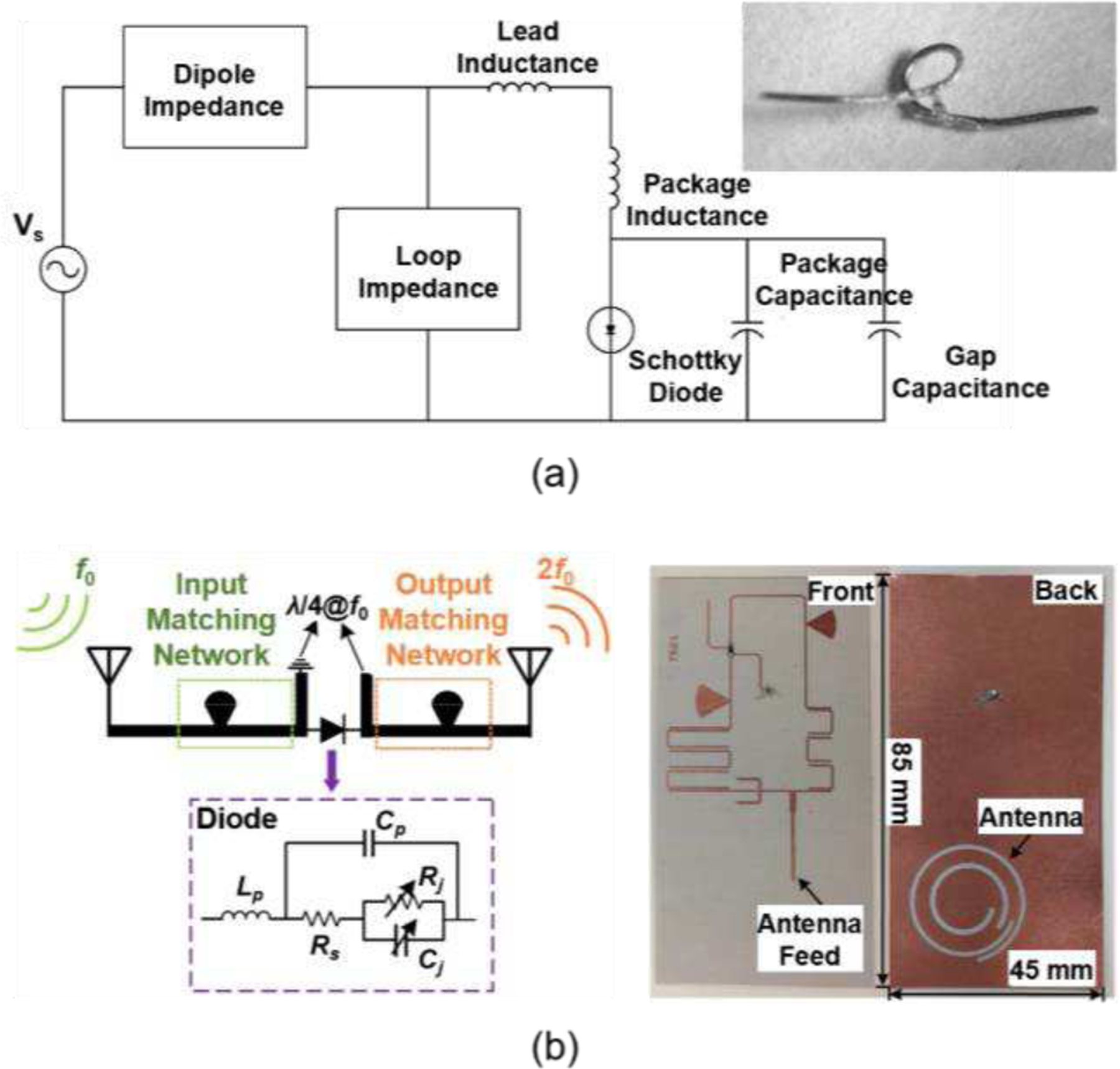
(a) Schematic of the transponder formed by a dipole antenna and a diode with a parallel connected inductive loop. Inset: photograph of the transponder [56]. (b) Schematic of the SMS7621-based harmonic transponder (left) and its photograph (right) [57].
It is established through Eq. (1) that the performance of a chipless tag can be optimized through the careful design of both the antenna and frequency multiplier. Ref. [56] achieves the optimal design by experimenting with different antennas while keeping the frequency conversion stage, specifically the diode and inductive loop, unchanged. In [57], the maximum readout range of a passive chipless tag is realized through the careful selection of the Schottky diode. The tag receives the RF signal at the fundamental frequency (3.5 GHz) and re-radiates the modulated signal at the second harmonic frequency (7 GHz). As shown in Fig. 2(b), the diode is considered to be the sole nonlinear component in a passive chipless transponder. Its conversion loss plays a significant role in determining the overall conversion efficiency of the transponder. A comparison of different Schottky diodes reveals that SMS7621 has a lower conversion loss of the tag, resulting in a longer detection range. Specifically, the SMS7621-based transponder can achieve a maximum readout distance of 8 m at room temperature, which is 1 m greater than that of the SMS7630-based transponder. Furthermore, it is found that low temperatures have the potential to increase the maximum readout range of the transponder. When the temperature is varied from −40°C to +40°C, the maximum readout distance increases from 7.4 m to 7.7 m for the SMS7621-based transponder, and from 6.4 m to 7.1 m (more than 10%) for the SMS7630-based transponder.
The transponders discussed in Refs. [56] and [57] can be classified as one-bit passive chipless tags. These tags utilize the presence or absence of a second harmonic signal to encode the logic “1” or “0”. Other notable examples of one-bit harmonic tags include those that utilize off-the-shelf Schottky diode (e.g., HSMS-2850) [61], as well as those that employ custom diodes (e.g., organic pentacene-based diodes) [62], and innovative antenna designs [63]. Single-bit harmonic tags, with relatively simple system architecture, have demonstrated their effectiveness in a diverse array of locating, sensing, and tracking applications [49], [60]–[63]. However, in certain identification applications, the utilization of multi-bit tags, which possess a greater coding capacity, may be deemed more suitable. Multi-bit tags utilize multiple resonant elements that can be configured in various forms, including but not limited to split-ring resonators (SRRs) [64], [68], spiral resonators [69], open-loop resonators [70], microstrip resonators [71], and antennas [64]. Fig. 3 presents two representative examples of multi-bit harmonic tags, where the resonant elements are implemented using (a) band stop SRRs and (b) narrowband diode antennas. The utilization of multiple resonant elements, each resonating at a specific desired frequency, enables the encoding of multi-bit identification information. One or a pair of resonant elements is responsible for encoding a single bit. The information retransmitted by the tag is encoded in the frequency spectrum, with the binary digits “1” and “0” represented by the presence or absence of resonant dips at a particular frequency band. To ensure optimal operation, the antenna and diode of multi-bit tags are typically required to cover a wide frequency range. In [64], a Schottky diode BAT 15–03 and a wideband bow tie antenna are utilized to meet the bandwidth requirements. Recent studies have also proposed chipless harmonic RFID transponders that execute multiplexed sensing by leveraging frequency and phase shifts [25], [72], [73]. The characteristics of these passive harmonic transponders are summarized in Table II.
Fig. 3.

Multi-bit harmonic transponders composed of (a) a wide-band bow-tie antenna and band stop split-ring resonators and (b) narrowband dipole antennas [64].
TABLE II.
Representatives of Passive Chipless and Chip-based Harmonic RFID Transponders
| Ref. | Type | Size (L×W) (mm2) | Frequency (GHz) | Data storage capacity | Read range (m)/Power | Antenna | Harmonic Generator | Other components | Comments |
|---|---|---|---|---|---|---|---|---|---|
| [56] | Chipless | 8×1§ | 9.41 & 18.82 | One-bit | 7 (4 kW) | A single dipole antenna | Schottky diode (HSCH-5340) | Inductive loop | Miniature, lightweight |
| [57] | Chipless | 85×45 | 3.5 & 7 | One-bit | 8 (25 dBm) | A dual-band antenna | Schottky diode (SMS7621) | Matching networks | Increased read range |
| [61] | Chipless | 75×65 | 1.2 & 2.4 | One-bit | 0.4 (8 dBm) | Nested slot antennas | Schottky diode (HSMS-2850) | Filtering and matching networks | Compact, paper-substrate |
| [62] | Chipless | ~200×200 | 0.0075 & 0.015 | One-bit | 0.125 (10 dBm) | Two coil antennas | Pentacene-based diode | None | Fully-organic, paper-substrate |
| [63] | Chipless | 9.5×9.5 | 5.9–6 & 11.8–12 | One-bit | 58 (0.1 W) | Modified Minkowski loops | Schottky diode (HSCH-5340) | None | Compact, low power, increased read range |
| [64] | Chipless | ~90×70 | 1.65–7.65 | 4 bits | 0.165† (13 dB) | A wideband bow tie antenna | Schottky Diode (BAT 15–03W) | Four SRRs | Multi-bit, low-cost |
| ~60×30 | 2–6 | 1 or 2 bits | Cross coupled dipoles | One or two SRRs | |||||
| ~50×25 | 2–6 | 2 or 3 bits | Four or six dipole antennas | None | |||||
| [25] | Chipless | N.A | 0.902–0.928 & 1.804–1.856 | Analog | 4.5 (10 dBm) | One Rx antenna and one Tx sensing antenna | MiniCircuit MK-546 | Sensing element | Low cost, high resolution |
| [72] | Chipless | 100×70 | 1.23, 1.73, & 2–6 | Analog | 4 (25 dBm) | Two Rx antennas and one Tx antenna | Schottky diode (HSMS-2850) | Filtering and matching networks | Flexible, low-profile, multi-functional |
| [75] | Chip-based | ~55×20# | 1 & 2 | Multi-bit (1 kHz)* | ~15 (30 dBm) | Two separate antennas | NLTL | Energy harvester, digital logic unit, etc. | High precision, high resolution, |
| [27] | Chip-based | ~80×25# | 0.915 & 1.83 | Multi-bit | 4.6 (0 dBm) | Two separate antennas | NLTL | Energy harvester, microcontroller, etc. | High precision, reduced interference |
| [77] | Chip-based | ~80×60 ~110×17 ~90×40⁑ |
0.434 & 0.868 | 8 bits | 1.8 (18 dBm) | Two meandered dipole antennas | NLTL | Energy harvester, modulation unit, etc. | Ultra-low power |
| [78] | Chip-based | N.A. | 0.95 & 1.9 | Multi-bit (500 Hz)* | ~1.5–2 (−20 dBm)|| | Two separate antennas | NLTL | Energy harvester, digital logic unit, etc. | Multi-functional, increased sensitivity |
| [79] | Chip-based | ~100×90 | 0.434 0.868 | Multi-bit (1 kHz)* | 8 (30 dBm) | A dual-band bow-tie shaped antenna | Schottky diode (HSMS-2850) | Energy harvester, microcontroller, etc. | Single-antenna, increased read range |
| [80] | Chip-based | 2.5×2.5# | 5.8 & 11.6 | 4 bits | N.A. | On-chip antennas | Injection locked LC oscillator | Rectifier, oscillator, register, amplifier, etc. | Fully-integrated, low-power |
| [81]‡ | Chip-based | ~30×20# | 2.4 & 4.8 | Multi-bit | 4† (25 dBm) | A wideband horn antenna | Controllable second-harmonic termination | Power management unit, microcontroller, etc. | Low-power uplink, uncompromised rectification |
| [82] | Chip-based | ~50×30 | 0.915 & 2.745 | Multi-bit | 6.5 (30 dBm) | A dual-band antenna | Internal circuitry of RFID IC | RFID IC | Third-harmonic, increased read range |
represents that while various design dimensions are analyzed in the reference, the value presented here correlates the maximum read range.
represents the distance between reader and tag during the experiments and does not indicate the maximum read range, while other values in this column represent the maximum read range, corresponding to the lowest conversion loss.
represents the power of harmonic signal converted by the tag, while other values in this column represent the fundamental power transmitted by the radar.
indicates the size of the tag circuit and does not include the size of antennas, while other values in this column indicate the overall dimensions of tags.
The three dimensions here represent the sizes of the Rx antenna (434 MHz), Tx antenna (868 MHz), and circuit of the tag, respectively.
focuses on the design and implementation of an integrated rectifier-transmitter for harmonic wireless sensing applications and does not fully demonstrate a chip-based RFID system.
represents the sampling rate or data modulation rate.
B. Chip-based RFID
Chip-based harmonic transponders are similar in design to conventional chip-based transponders, but possess an additional functional block for frequency conversion. The functional components that are common to both conventional and harmonic transponders with chips include (1) antennas for receiving and re-radiating signals; (2) an energy harvester, which captures transmitted interrogation power and converts it to usable DC energy to power the microchip; and (3) integrated circuits (IC) for generating and storing identification data. The chip-based harmonic tags exhibit a greater diversity of configurations in comparison to their chip-less counterparts. As reported in Ref. [74], a chip-based harmonic RFID system is proposed for the localization of objects with high precision and resolution. Fig, 4(a) illustrates the schematic and image of the harmonic transponder. In this design, Antenna 1 (ANT 1) is utilized to receive the RF signal at the fundamental frequency and to provide the fundamental signal to the energy harvesting and downlink demodulation units. The energy harvester powers the digital logic circuits and the tag receiver. Furthermore, Antenna 2 (ANT 2) is also employed to receive the fundamental signal, which is then transmitted to a nonlinear transmission line (NLTL). The NLTL, composed of ladders of inductors and capacitors, is responsible for generating the second harmonic signal and reflecting it back to ANT 2, which subsequently retransmits the signal to the reader. The RFID system operates in the UHF band, with the fundamental (downlink) frequency of around 1 GHz and the second harmonic (uplink) frequency of around 2 GHz. It is demonstrated that the system achieves millimeter-level ranging resolution and centimeter-level precision with a sampling rate of 15 Hz. Additionally, a thorough investigation is carried out to examine the effects of the quantity of tags on critical system parameters, including the rate of data collection, power consumption, and inaccuracies in location estimation. The results point out that the proposed harmonic RFID system, aided by code division multiple access (CDMA), can enable the concurrent localization of multiple tags. The transponder design presented in Ref. [74] has since been adopted in subsequent studies referenced as Refs. [75], [76].
Fig. 4.

Schematic and circuit implementation of the chip-based harmonic transponders, as in (a) Ref. [74] and (b) Ref. [77], which comprise Rx and Tx antennas, energy harvesters, digital circuits, and harmonic generators.
In [77], a harmonic RFID tag with a representative configuration is utilized. As depicted in Fig. 4(b), the interrogation signal is received via ANT 1 and subsequently divided into two paths. One path is converted to DC power through an energy harvester, providing energy for the tag circuits, while the other path passes through a frequency multiplier (NLTL) before being retransmitted by ANT 2. The resulting harmonic signal, backscattered by the transponder, is then received by the reader and undergoes post-signal processing to obtain the transmitted ID. The tag configuration presented in Ref. [77] is consistent with those reported in recent literature [27], [78], which may be streamlined by incorporating a single broadband or multi-band antenna in place of the two separated antennas [79]. We note that chip-based harmonic RFID systems predominantly operate within the UHF bands, owing to the comparatively low path loss and accessibility of unlicensed frequency bands. These systems may be optimized for higher operating frequencies by leveraging on-chip technology [80] and advanced circuit designs [81].
The utilization of the second harmonic signal in the aforementioned harmonic RFID systems has been established as an efficient method for mitigating self-jamming and multipath propagation. In recent developments, the application of the third harmonic signal in RFID systems has been proposed as a means of enhancing energy harvesting [26], activating sensor units [16], and facilitating communication between the tag and reader [82]. The third harmonic signal can be utilized as the RF input to an energy harvester, which is then rectified to DC energy and reinjected into the RFID chip. This methodology improves the sensitivity of the chip, resulting in a 2.5-m enhancement of the readout range [26]. Furthermore, the third harmonic signal can directly provide energy to a sensor linked with the tag, thereby expanding the functionality of the tag [16]. Additionally, as shown in Fig. 5, the third harmonic can also be used for downlink and uplink communication between the tag and reader [82]. To achieve this, an RF harmonic interface layer is implemented in the conventional reader to transmit the interrogation signal and receive the third harmonic signal containing identification information. A custom-designed dual-band harmonic tag antenna, which operates at both fundamental and third harmonic frequencies, is coupled to a traditional RFID chip to increase third harmonic radiation efficiency. The transponder re-radiates the third harmonic signal (2745 MHz) once it receives the fundamental signal (915 MHz). The proposed third harmonic RFID system not only preserves the advantages of the second harmonic RFID system, but also offers enhanced readout range, increased data rate, and greater potential for various applications.
Fig. 5.

Harmonic RFID system which utilizes the third harmonic signal for downlink and uplink transmissions between the reader and tag. The system consists of a conventional UHF interrogator, a custom designed harmonic RF layer and a harmonic RFID tag [82].
C. Antennas for RFID
The harmonic RFID transponder necessitates the utilization of either two separate antennas or a dual-band/wide-band antenna for the reception of the fundamental frequency and the transmission of the harmonic frequency. It is desirable for antennas to possess satisfactory performance within a compact size. The miniature and lightweight characteristics of the antenna promote its implementation on small objects. The high gain and directivity characteristics of the antenna enhance its capability of producing a sufficient directional radiation field, potentially extending the readout range. In specific RFID applications, a wide operating bandwidth is desirable to cover the entire operating frequency range [64], [72]. The polarization of the antenna is also a crucial factor that needs to be considered, as careful selection of the polarization of the tag antenna and reader antenna can minimize polarization loss and improve transmission distance [50]. Additionally, it is imperative to take into account the potential impact of external factors, such as metallic objects or human presence, on the performance of the RFID antenna when implementing the system in specific scenarios [83]–[85].
To date, numerous antennas have been developed to meet the requirements of RFID applications [84]–[91]. A comprehensive summary of representative works in antenna design for RFID is presented in Table III, including the performance characteristics of the antennas. In [84], an electrically small antenna is proposed, which features a gain of 0.08 dBi at the operating frequency of 923 MHz. As depicted in Fig. 6(a), the antenna has a dual-layer structure, utilizing two loaded via-patches that are fed through a dual-element planar inverted-F antenna array. The proposed antenna offers two main advantages: its compact size, measuring , and its reliable performance when mounted on metallic surfaces, making it well-suited for applications involving metallic objects. Furthermore, a capacitively coupled patch antenna presented in Ref. [85] can also be mounted on metallic objects [Fig. 6(b)]. The antenna exhibits a −10 dB bandwidth of 43 MHz (889–932 MHz), spanning the 902–928 MHz UHF band. This antenna, with its wide bandwidth, may be a viable option for the previously mentioned multi-bit RFID systems.
TABLE III.
Representatives of Antennas for RFID Applications
| Ref. | Antenna Configuration | Size (L×W×H) (mm3) | Frequency (GHz) | Maximum Realized Gain (dBi) | Bandwidth (MHz) | Fractional Bandwidth (%) | Radiation Efficiency (%) | Characteristics |
|---|---|---|---|---|---|---|---|---|
| [84] | Dual-layer, two patches fed via a PIFA array | 26×14×2.4 | 0.923 | −1.4 | 16* | 1.7* | 23 | Electrically small, metal-mountable |
| [85] | A meandered patch fed by a coupled microstrip line | 100×50×0.8 | 0.915 | −3.8§ | 43 | 4.7 | N.A. | Broadband, metal-mountable |
| [86] | Slotted, magnetic dipole-based antenna | 180×60×20† | 0.92 | 5.3 | 62 | 6.7 | N.A. | Low-profile, vertical polarized |
| [87] | A single longer dipole and a pair of shorter dipoles | 43×26×0.5† | 2.4 5 |
7.5 9.5 |
120 2100 |
5 42 |
>95 | Dual-band, single-substrate |
| [88] | SIR coupled dipole antenna | 25×9×1.6 | 2.4 5–6 |
2.6 3.6 |
95 1380 |
4.0 26.5 |
88.6 96.87 |
Dual-band, broadband, electrically small |
| [89] | Hybrid-fed microstrip antenna | ~35×35×1.5† | 3 6 |
1.17 3.33 |
50 240 |
1.7 4.0 |
40–70 | Dual-fed, low-profile |
| [90] | Diamond-shaped patch antenna | 150×150×1.66† | 0.915 2.45 |
7.8 9.4 |
18 80 |
2.0 3.3 |
87 94 |
Dual-band, single-substrate |
| [91] | Rectangular slot antenna | 2.5×2.5×2.5† | 24 40 |
−1 0 | ~5000 ~8000 |
19 20 |
41 31 |
On chip, dual-band, millimeter-wave |
represents −3 dB (half-power) bandwidth/fractional bandwidth, while others represent −10 dB bandwidth/fractional bandwidth.
represents that the results are obtained from simulations, while others are obtained from measurements.
refers solely to the dimensions of the resonator or radiator and does not encompass the overall dimensions of the antenna.
Fig. 6.

(a) An electrically small, metal-mountable antenna operating at 923 MHz [84]. (b) A wideband, metal-mountable antenna operating in the range of 889–932 MHz [85].
Dual-band or wideband antennas, which enable simultaneous reception and transmission using a single antenna, are generally considered a superior option to using separate receiving and transmitting antennas [87]–[91]. The utilization of dual-band or wideband antennas in the design of harmonic RFID systems can significantly decrease the overall dimension and complexity of the system, while concurrently ensuring sufficient isolation between the fundamental and harmonic signals. A dual-band directional antenna operating at 2.4 GHz and 5 GHz is presented in [87]. The dual-band antenna comprises a single longer dipole with capacitive loadings and a pair of shorter dipoles to cater to the lower and upper frequency bands, respectively. All the dipole structures, as well as the microstrip feed line, are printed on a common substrate, facilitating a compact and planar configuration [Fig. 7(a)]. The experimental results indicate that the antenna exhibits antenna gains of 7.5 dBi and 9.5 dBi for the 2.4-GHz and 5-GHz bands, respectively. The −10 dB bandwidths for the 2.4-GHz band and the 5-GHz band are respectively determined to be 120 MHz and 2100 MHz, corresponding to relative bandwidths of 5% and 42%. Moreover, a coplanar, dual-band antenna is proposed in Ref. [88] for RFID applications in the 2.4-, 5.2-, and 5.8-GHz frequency ranges. As illustrated in Fig. 7(b), the design employs a stepped impedance resonator (SIR) to attain resonance at the lower frequency and a modified planar dipole that is coupled with the SIR to achieve resonance at the higher frequency with wide-band coverage. The resulting antenna exhibits a nearly omnidirectional radiation pattern and achieves maximum gains of 2.6 dBi at 2.48 GHz and 3.6 dBi at 5.35 GHz. In a more recent study [89], a compact hybrid-fed microstrip antenna is proposed for harmonic RFID applications. The antenna features an outer split ring patch operating at the fundamental frequency and an inner circular patch operating at the second harmonic. The proposed antenna demonstrates satisfactory gain and radiation efficiency, and has been effectively implemented in a harmonic microfluidic sensor [92].
Fig. 7.

Dual-band RFID antennas operating at (a) 2.4 GHz and 5 GHz and [87] (b) 2.4-, 5.2-, and 5.8-GHz frequency bands [88].
IV. Applications of Passive Harmonic RFIDS
Passive harmonic RFID technology has demonstrated remarkable advantages in various domains for identification [64], [77], tracking [93], [94], and monitoring of objects [95]–[97]. In this section, we systematically categorize the diverse applications of passive harmonic RFID systems documented in academic literature. A comprehensive overview of their utilization is provided, offering detailed information on each application. The objective is to impart a systematic and thorough understanding of the numerous applications of passive harmonic RFID systems.
A. Tagging and Identification
Tagging and identification is probably considered as one of the most fundamental applications of RFID systems. In [77], a compact and low-power harmonic RFID tag is designed and evaluated experimentally. The proposed tag is powered by an energy harvesting unit and can function with received signal strength as low as −6 dBm. The digital modulation circuitry of the RFID tag employs a shift register to create the identification code, which is loaded in parallel as an 8-bit data stream and transmitted in series upon deactivation. An increased number of bits may also be possible by incorporating multiple shift registers. Additionally, an interrogator is designed to power the tag and read the transmitted ID within a range of 1.8 m when the transmitted power is 18 dBm. The read range could be further extended by increasing the transmitted power or implementing high-gain antennas. Moreover, harmonic transponders with larger data storage capacities and faster data transmission speeds may be achievable with more sophisticated integrated circuits [75], [77].
Besides chip-based harmonic RFID tags, chipless harmonic RFIDs have been increasingly used for identification and tagging as an attractive alternative to traditional barcodes [58], [64]. The chipless RFIDs employ resonators or antennas that operate at individual frequencies to generate single-bit or multiple-bit identification information. Despite the benefits of low cost, simple design, and lightweight, many chipless RFIDs, as well as a portion of chip-based RFIDs, still experience interference issues in environments with multiple tags or readers. To address this challenge, the CDMA protocol has been proposed for harmonic RFID systems [74], [76]. This protocol enables the system to handle situations where a large and unknown number of tags are present. Furthermore, the CDMA protocol allows the tag to differentiate between downlink commands from multiple readers and respond accordingly, thus effectively addressing reader-to-reader collisions with a minimal rate of read failure. The harmonious integration of the harmonic technology and the CDMA protocol offers a promising solution for identification in complex and dynamic environments with multiple paths and scattering.
B. Tracking and Localization
Harmonic RFID systems have been established as a reliable approach for accurately tracking insects that fly at low altitudes or over flat terrain [48], [49], [56]. Psychoudakis et al. developed a harmonic RFID system aimed at monitoring the migration of the Emerald Ash Borer [63]. This system comprises a low-power, portable radar unit and a compact RF tag that can be affixed to the insect. The integration of the Avago/Agilent HSCH-5340 diode and a modified Minkowski loop antenna significantly improves the harmonic conversion efficiency and decreases the tag size, in comparison to previous systems. The system boasts a remarkable detection range of up to 58 m, when operating at 5.9 and 11.8 GHz with 0.1 W transmit power and 22 dBi Rx/Tx antenna gain. In a more recent study reported in Ref. [55], the miniature passive tags attached to the insects allow the harmonic RFID system to effectively track the flight trajectory and nest location of the insects. The georeferenced tracks of hornets in the vicinity of Calvo, located in the interior of Liguria, Italy, are depicted in Fig. 8(a), where the entomological radar is represented by a blue square situated in the center of the image. The small, colored squares along the tracks serve as visual markers to indicate the precise location of the hornets. This study utilizes pulse compression technique to enhance the sensitivity of the system, achieving a total detection range of approximately 500 m.
Fig. 8.
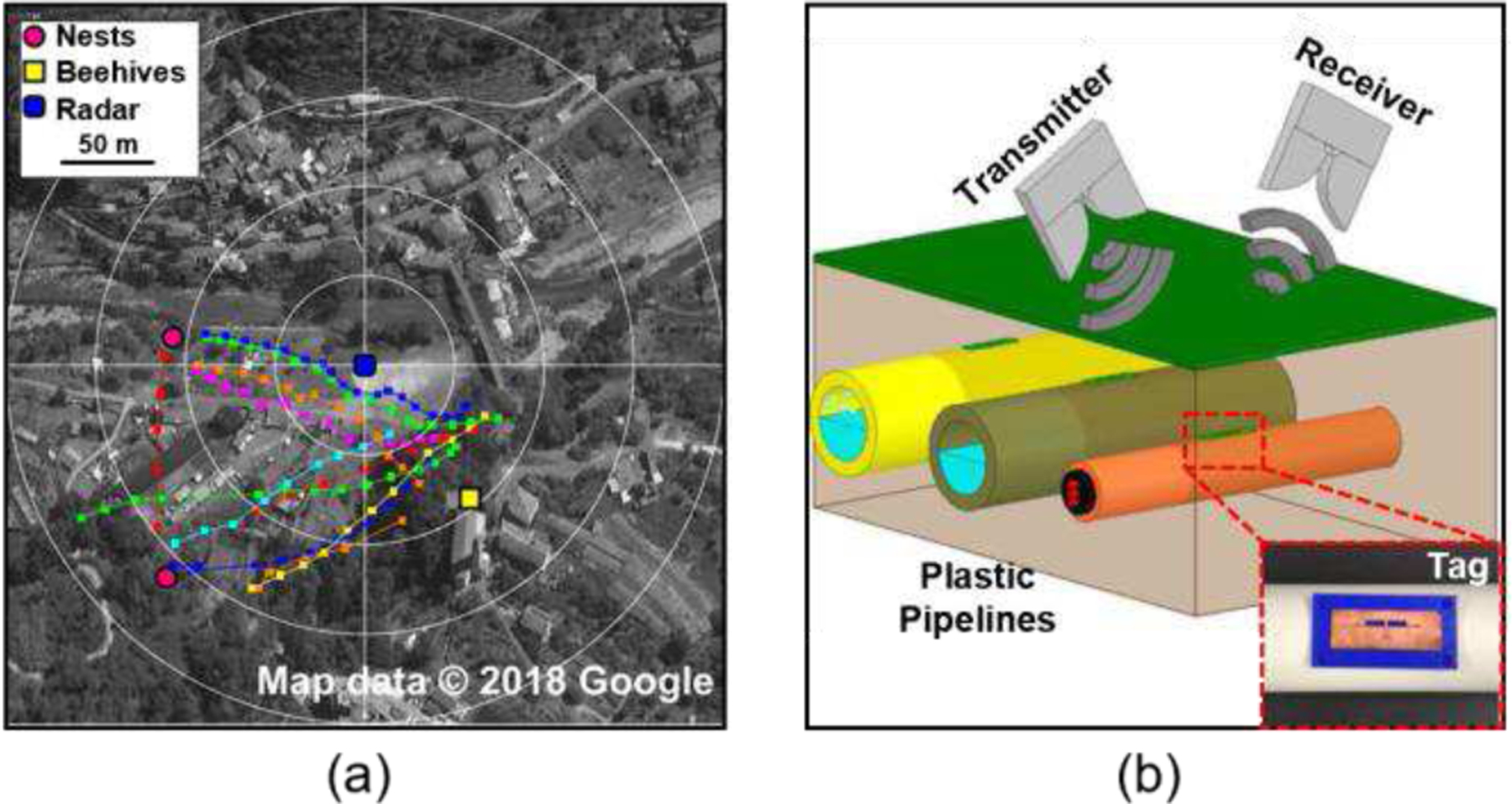
Application of harmonic RFID systems for (a) tracking of Asian hornets [55] and (b) localizing buried plastic pipelines [94].
The implementation of passive harmonic tags has proven to be an effective means of localizing buried or subterranean objects [93], [94], [98]. As discussed in Ref. [93], a frequency-modulated harmonic tag can adjust its modulation frequency based on the target asset. Results from the study indicate that the tag could be read from a depth of up to 60 cm in soil with 25% water content. Another study (Ref. [94]) suggests the utilization of a 3-D printed tag attached directly to the buried asset (e.g., plastic pipelines) for localization purposes, as shown in Fig. 8(b). The location and orientation of the pipeline can be determined through analysis of the polarization of the tag antenna. Results show that the system could detect the tag when it is buried 20 cm beneath the surface. Furthermore, the utilization of harmonic tags has also been shown to accurately track the burial depth of underground pipelines, as discussed in Ref. [98]. By employing a genetic algorithm-based post-processing method, the phase information of the received harmonic signal can provide an accurate estimation of the burial depth. This study presents a design for harmonic tags that are capable of detecting underground pipelines at depths up to 5 feet in various soil media with differing moisture contents.
C. Sensing and Monitoring
Passive harmonic RFID technology has been widely employed in various domains for wireless sensing and monitoring of physical and chemical parameters, such as temperature, humidity, strain, gas, and pH [99], [96], [95]. In most application scenarios, variations in parameters to be monitored can cause a shift or even disappearance of the backscattered harmonic signal, thus allowing the sensing function. Here, we thoroughly examine three representative areas of its application: food quality monitoring [95], [100]–[102], crack monitoring [96], [103], [104], and liquid monitoring [25], [29], [92], [105], [106]. The monitoring of food quality is of paramount importance in ensuring the quality and safety of food products during prolonged storage. A compact and cost-effective harmonic RFID sensor is developed in Ref. [95] for monitoring pH levels, a critical indicator of food quality in packaged food products such as milk and meat. As shown in Fig. 9(a), the sensor comprises a dual-band annular ring antenna, a harmonic generator, and a varactor-based sensing element. The capacitance of the varactor changes with variations in pH, resulting in a shift in the resonant frequency of the receiving antenna. The sensor demonstrates a sensitivity of 4 MHz per pH unit change, with a pH range of 3 to 8. Its compact size and comparable range and sensing capabilities make it a desirable alternative to previous harmonic sensors. Further seminal works relevant to harmonic transponder-based food sensing can be explored in Refs. [100]–[102].
Fig. 9.

Application of harmonic RFID systems for (a) sensing pH of packaged food products [95], (b) monitoring the occurrence of cracks [96], and (c) determining the type (left, [92]) and volume (right, [25]) of liquid.
A frequency-doubling antenna sensor for wireless monitoring of strains and cracks is proposed in Ref. [96]. This sensor consists of two patch antennas and a diode-based frequency multiplier [Fig. 9(b)]. The resonance frequency of the patch antenna is highly sensitive to the length of the antenna and the substrate surface, and thus undergoes a substantial shift upon the occurrence of strain or crack. Further advancement in the concept is presented in Ref. [104], by incorporating a compact design for crack monitoring through the integration of two orthogonally positioned annular slot antennas, with one nested inside the other. Both designs exhibit enhanced interrogation distance, improved sensitivity, and notably reduced background scatters and interferences.
In the realm of liquid sensing, a recent study (Ref. [92]) presents a passive harmonic sensor consisting of a reconfigurable dual-band microstrip antenna and a passive frequency doubler, as depicted in Fig. 9(c). The peak of the frequency hopping spread spectrum can be modified by the dielectric properties of liquid mixtures, allowing for the detection of the type of liquid in the microfluidic cavity. Ref. [25] employs a harmonic transponder to accurately sense liquid volume at the microliter scale. The transponder comprises a metamaterial-inspired electrically-small antenna connected to a passive nonlinear frequency multiplier [Fig. 9(c)]. The frequency response of the transponder is optimized to be highly sensitive to liquid volume. With the implementation of post-processing algorithms, a resolution of and an accuracy of approximately 10% can be achieved, making the system a viable option for economic and battery-free wireless liquid-level monitoring.
D. Biomedical and Healthcare Applications
In recent years, passive harmonic transponders have gained popularity in the biomedical and healthcare fields due to their economical, lightweight, fully-passive, and low-maintenance nature. As shown in Fig. 10(a), a harmonic sensing tag is implemented to wirelessly monitor the vital signs of animals, including heartbeat and respiration rate [97]. The study utilizes a chip-based harmonic transponder powered by energy harvesting, which is suitable for monitoring small conscious animals in their natural habitats. It is indicated that simultaneous detection of multiple tags can be achieved using a specific reader. Importantly, this non-invasive sensor captures the motion within and on the animal’s body without causing harm or disrupting their circadian rhythms, ensuring animal welfare and minimizing the potential for pain or distress. An analogous methodology can be effectively utilized to continuously monitor the vital indicators of human patients [78], including blood pressure, heart rate, respiration rate, and breath effort. By adopting this approach, healthcare professionals can obtain valuable information regarding the patient’s well-being and take prompt action to address any abnormalities. In [107], a wireless sensing system based on harmonic backscattering is developed to continuously monitor deep surgical wounds during the post-operative recovery period. A reader placed near the human body can wirelessly read out information related to the wound status at the second harmonic frequency. Experiments conducted using live pigs show that the system is capable of monitoring gastric leakage, suture breakage, and tissue micromotions. Furthermore, in rats, the system demonstrates robust and prolonged monitoring capabilities without negatively affecting wound healing. This innovative approach provides a convenient and efficient means of monitoring deep surgical wounds in real time, making it a valuable tool for healthcare professionals and researchers.
Fig. 10.
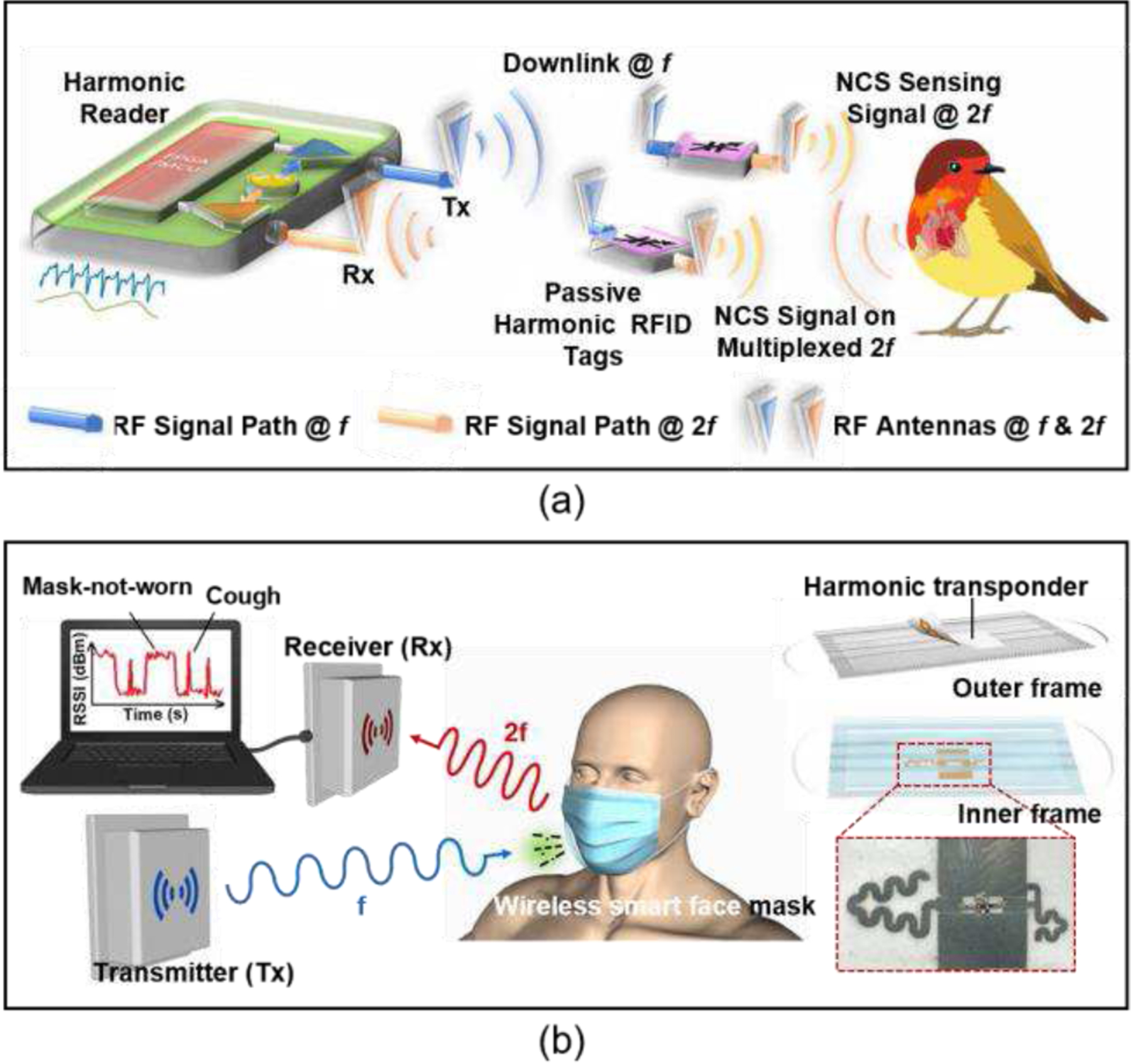
Harmonic RFID systems in biomedical and healthcare applications. (a) Monitoring the heartbeat and respiratory rate of small conscious animals, using harmonic RFID and near-field coherent sensing (NCS) principle [97]. (b) Monitoring cough frequency and mask-wearing status during the spread of COVID-19 [108].
The recent COVID-19 pandemic has sparked the development of smart face masks. A recent study, as reported in Ref. [108], describes the creation of a smart face mask that combines a traditional surgical mask with a harmonic transponder. The purpose of this mask is to wirelessly monitor coughing, a common symptom of respiratory illnesses, and to identify mask-wearing status in crowded indoor spaces where mask usage is recommended [Fig. 10(b)]. The harmonic transponder operates by detecting separation from the face, as the presence of the human body affects the performance of the transponder antennas. More importantly, unlike traditional harmonic tags fabricated with rigid circuit boards, this transponder is constructed using conductive silver nanowires and a soft, highly flexible, and porous substrate, providing superior wearing comfort. The wireless smart face mask holds great potential for curbing the transmission of respiratory diseases during pandemics and for enhancing health monitoring in various clinical, biomedical, and healthcare IoT applications.
The evaluation of electromagnetic compatibility (EMC) and specific absorption rate (SAR) is of great importance in the field of biomedical and healthcare applications. For the harmonic RFID systems examined in our research, the orthogonality between the downlink and uplink frequencies may provide them with excellent EMC performance. Moreover, these harmonic RFID systems are entirely passive, devoid of integrated power sources, and exclusively re-emit backscattered electromagnetic radiation originating from the interrogator. Consequently, this leads to diminished power levels and mitigated SAR considerations. The highest average SAR for a passive harmonic transponder, reported in Ref. [23], is 0.62 W/kg, which is substantially lower than the European standard threshold of 2 W/kg. It is imperative to underscore that harmonic RFID systems intended for biomedical applications must conform to critical standards, including those stipulated in the IEC/EN 60601–1 EMC standard and the IEEE/IEC 62704–4 SAR standard.
V. Challenges and Future Directions
The advent of passive harmonic RFID technology has yielded substantial advancements in diverse industrial sectors and applications. Compared to active RFIDs, passive harmonic RFIDs boast low costs, long operational lifetimes, and ease of maintenance. Additionally, passive harmonic RFIDs have the capability to mitigate clutter, self-jamming, and multipath interference, which are prevalent issues in conventional RFID systems. However, despite these benefits, there remain several challenges that must be addressed to further enhance the performance of passive harmonic RFID systems and facilitate their commercialization.
A. Challenges and Possible Solutions
1). Limited Read Range and Accuracy:
Passive harmonic RFID has a restricted readout range due to the absence of an integrated power source, i.e., a battery. The tag relies solely on the power received from the interrogator, resulting in a low power level that is vulnerable to interference from factors such as antenna orientation, propagation loss, and obstacles in the signal path. This, in turn, contributes to a decreased read accuracy, rendering accurate readout difficult in such circumstances. These limitations may hinder the applications of passive harmonic transponders in real-time, continuous, and long-range tracking and monitoring. To mitigate this drawback, polarization-matched high-gain antennas and low conversion loss harmonic generators may be employed. Furthermore, the implementation of self-interference cancellation techniques and windowing techniques can reduce background noises and interferences, thereby enhancing the received harmonic signal and ultimately increasing both read distance and accuracy [109].
2). Limited Data Storage Capability and Sensing Capability:
Passive RFID tags, either lacking integrated circuits or featuring low-power, rudimentary circuitry, possess limited data storage capacities. Even with the assistance of digital circuitry, the maximum storage capacity of passive tags barely reaches 128 bytes, significantly less than that of active tags with substantial data storage and advanced data retrieval ability. Furthermore, the sensing capabilities of passive RFIDs are also restricted, with passive harmonic sensors predominantly relying on monitoring the phase and amplitude of resonance. This poses challenges when passive harmonic sensors are used in monitoring multiple parameters, especially in biomedical and wearable applications. To address this, several approaches have been proposed to enhance the storage capacity of passive tags, such as utilizing high-Q resonators and employing hybrid encoding techniques [110]. Moreover, the simultaneous measurement of multiple parameters has become feasible with passive harmonic RFID systems (Refs. [72], [78], [111]).
3). Multi-tag and/or Multi-reader Collision:
Harmonic technology has effectively addressed the issue of electromagnetic interference caused by reflection and scattering from surrounding environments. However, reading passive harmonic tags in areas where there are multiple tags or multiple readers remains a significant challenge. The reader struggles to differentiate between multiple tags, and the tag is unable to distinguish signals from different readers. To mitigate this problem, various signal processing algorithms, including tree-based time division multiple access [112], code division multiple access [74], [76], fractional Fourier transform [113], and short-time matrix pencil method [114], have been employed and have demonstrated promising results. However, a reader with post-processing units, as well as antennas capable of handling both fundamental and harmonic frequencies, may prove to be more complex and costly compared to that of traditional systems. It is anticipated that advancements in circuit and system design will tackle this issue in the impending future.
B. Future Directions
1). Fully Printable Harmonic RFID Tags:
In recent years, the development of fully printable RFID tags has garnered significant attention within the research community. These novel tags diverge from conventional RFID systems, which typically employ substrate materials such as FR-4 and RT-Duroid. Instead, fully printable RFID tags can be fabricated on a diverse range of substrates, including paper [61], [62], cloth [78], plastic [58], and a variety of soft nanomaterials [108]. These fully printable RFID tags involve the utilization of conductive ink, which can be printed onto ultra-thin, flexible substrates using advanced printing techniques, such as gravure printing and inkjet printing [115], [116]. The emergence of fully printable RFID tags has several notable implications. Firstly, the adoption of these tags is likely to result in a substantial reduction in manufacturing costs. Secondly, the inherent flexibility and adaptability of these tags make them particularly well-suited for wearable applications, opening up new possibilities for integration across numerous industries. The development of fully printable RFID tags may represent a promising advancement in the field, offering numerous potential benefits and applications.
2). Graphene Harmonic RFID Sensors:
Very recently, graphene harmonic sensing systems have surfaced as a revolutionary development in this field [117], [118]. Graphene field-effect transistors (GFETs) possess a unique drain current-gate voltage characteristic that manifests as a symmetric “V-shape”. This feature endows GFETs with the ability to convert incoming RF signals to their second harmonic, thereby serving as a simple yet effective frequency doubler capable of operating at extremely high frequencies, reaching up to tens of GHz. More importantly, unlike conventional frequency multipliers that serve solely as frequency multipliers, GFETs exhibit the capability of simultaneously acting as frequency doublers and sensing elements. The exceptional sensitivity of graphene’s electrical conductivity to chemical or biological dopants has been well established [118]–[120]. By utilizing a single back-gate GFET, it is feasible to attain a frequency-doubling transponder sensor with exceptional sensitivity towards variations in the doping concentrations on the graphene surface [121]. These variations give rise to a shift in the Dirac point, also recognized as the charge neutrality point, resulting in a highly responsive output signal at the second harmonic. Nevertheless, to enable the operation of a single-GFET-based harmonic sensor, a drain-to-source bias may still be required. To address this constraint, dual-ring, and quad-ring GFET circuits, coupled with antennas, have been proposed as a promising strategy for achieving fully-passive GFET-based harmonic sensors [122]–[125]. These GFET sensing-modulators offer integrated sensing, frequency modulation, and energy harvesting functionalities, enabling reliable, passive harmonic sensing in a compact, lightweight circuit. Consequently, the GFET-based harmonic sensors hold immense potential for advancing the field of harmonic technology towards the next generation.
3). Toward Terahertz and Optical Applications:
Plasmonic nanodevices with strong optical nonlinearity is a nascent technology that has sparkled recently and begun making waves. The concept of nonlinear harmonic sensor can also be extended to the optical domain by using plasmonic nanoantennas made of nonlinear nano-metals or loaded with nonlinear optical nanoparticles [126]–[130] to generate high harmonics. This allows one to realize optical harmonic tags based on nonlinear nanoantennas that can detect local dielectric and molecular properties at high resolution. For instance, the multipath scattering that occurs at the near-field scanning optical microscopy (NSOM) tip can be greatly suppressed. In [131], Farhat et al. have proposed an optical harmonic sensor based on the dual-resonance gold-molecule-silver nanodipole antenna and showed that the spectral form of the second-harmonic scattering could sensitively reveal the local properties of molecules. This may lead to a new route towards optical molecular sensors and optical identification (OPID) of biological, genetic, and medical events for the future “internet of nano-things.”
VI. Conclusion
In this article, we provide a thorough examination of passive harmonic RFID systems. Our analysis emphasizes the capability of these systems to effectively suppress electromagnetic interference and enhance overall performance compared to conventional RFID systems. We commence with a historical overview of conventional RFID systems, followed by a comparison to passive harmonic RFID systems. This comparison highlights the cost-effectiveness, low maintenance requirements, and extended operational lifespan of passive harmonic RFID systems. We delve further into the realm of passive harmonic RFID systems, presenting a detailed analysis of both chipless and chip-based variants. The advantages and limitations of these systems are highlighted, and a number of examples are provided to illustrate their design. Additionally, we present a comprehensive overview of the applications of passive harmonic RFID systems, including object identification, tracking, monitoring, and recent developments in the biomedical and healthcare sectors. The final section of the article provides insight into the challenges and future prospects of passive harmonic RFIDs, emphasizing the potential for further development and improvement.
This article constitutes a valuable resource for professionals and practitioners in the field of passive harmonic RFID systems and their applications. Our comprehensive analysis of passive harmonic RFID systems, covering aspects from design, applications to future prospects, furnishes a comprehensive understanding of this rapidly evolving technology.
Acknowledgments
This work was supported by National Science Foundation (ECCS-1914420) and National Institute of health (R01EB033371)
Contributor Information
Zhilu Ye, Department of Electrical and Computer Engineering, University of Illinois at Chicago, Chicago, IL 60607 USA.
Minye Yang, Department of Electrical and Computer Engineering, University of Illinois at Chicago, Chicago, IL 60607 USA.
Yichong Ren, Department of Electrical and Computer Engineering, University of Illinois at Chicago, Chicago, IL 60607 USA.
Cheng-Hsien Jonathan Hung, Maxim Integrated Inc., Dallas, Texas 75240, USA.
Chung-Tse Michael Wu, Department of Electrical and Computer Engineering, Rutgers University, Piscataway, NJ 08854, USA.
Pai-Yen Chen, Department of Electrical and Computer Engineering, University of Illinois at Chicago, Chicago, IL 60607 USA.
References
- [1].Rekik Y, Sahin E, and Dallery Y, “Analysis of the impact of the RFID technology on reducing product misplacement errors at retail stores,” Int. J. Prod. Econ, vol. 112, no. 1, pp. 264–278, Mar. 2008, doi: 10.1016/j.ijpe.2006.08.024. [DOI] [Google Scholar]
- [2].Jones M, Wyld D, and Totten J, “The Adoption of RFID Technology in the Retail Supply Chain,” Coast. Bus. J, vol. 4, no. 1, Feb. 2022. [Google Scholar]
- [3].Sun C, “Application of RFID Technology for Logistics on Internet of Things,” AASRI Procedia, vol. 1, pp. 106–111, Jan. 2012, doi: 10.1016/j.aasri.2012.06.019. [DOI] [Google Scholar]
- [4].Lin C and Ho Y, “RFID technology adoption and supply chain performance: an empirical study in China’s logistics industry,” Supply Chain Manag. Int. J, vol. 14, no. 5, pp. 369–378, Jan. 2009, doi: 10.1108/13598540910980288. [DOI] [Google Scholar]
- [5].Yao W, Chu C-H, and Li Z, “The Adoption and Implementation of RFID Technologies in Healthcare: A Literature Review,” J. Med. Syst, vol. 36, no. 6, pp. 3507–3525, Dec. 2012, doi: 10.1007/s10916-011-9789-8. [DOI] [PubMed] [Google Scholar]
- [6].Yao W, Chu C-H, and Li Z, “The use of RFID in healthcare: Benefits and barriers,” in 2010 IEEE International Conference on RFID-Technology and Applications, Jun. 2010, pp. 128–134. doi: 10.1109/RFID-TA.2010.5529874. [DOI]
- [7].Amendola S, Lodato R, Manzari S, Occhiuzzi C, and Marrocco G, “RFID Technology for IoT-Based Personal Healthcare in Smart Spaces,” IEEE Internet Things J, vol. 1, no. 2, pp. 144–152, Apr. 2014, doi: 10.1109/JIOT.2014.2313981. [DOI] [Google Scholar]
- [8].Ruiz-Garcia L and Lunadei L, “The role of RFID in agriculture: Applications, limitations and challenges,” Comput. Electron. Agric, vol. 79, no. 1, pp. 42–50, Oct. 2011, doi: 10.1016/j.compag.2011.08.010. [DOI] [Google Scholar]
- [9].Farooq U, ul Hasan M, Amar M, Hanif A, and Usman Asad M, “RFID Based Security and Access Control System,” Int. J. Eng. Technol, pp. 309–314, 2014, doi: 10.7763/IJET.2014.V6.718. [DOI]
- [10].Velayo JRL, Moraga SD, Batalla MYC, and Bringula RP, “Development of a Passive RFID Locator for Laboratory Equipment Monitoring and Inventory System,” Proc. Int. Multiconference Eng. Comput. Sci, vol. 1, 2013. [Google Scholar]
- [11].Malik W, “Low Frequency Reader and Antenna Design Using RFID,” Univers. J. Electr. Electron. Eng, vol. 3, no. 1, pp. 1–5, Jan. 2015, doi: 10.13189/ujeee.2015.030101. [DOI] [Google Scholar]
- [12].Zalbide I, D’Entremont E, Jiménez A, Solar H, Beriain A, and Berenguer R, “Battery-free wireless sensors for industrial applications based on UHF RFID technology,” in 2014 IEEE SENSORS, Nov. 2014, pp. 1499–1502. doi: 10.1109/ICSENS.2014.6985299. [DOI]
- [13].Chawla V and Ha DS, “An overview of passive RFID,” IEEE Commun. Mag, vol. 45, no. 9, pp. 11–17, Sep. 2007, doi: 10.1109/MCOM.2007.4342873. [DOI] [Google Scholar]
- [14].Dziadak K, Kumar B, and Sommerville J, “Model for the 3D Location of Buried Assets Based on RFID Technology,” J. Comput. Civ. Eng, vol. 23, no. 3, pp. 148–159, May 2009, doi: 10.1061/(ASCE)0887-3801(2009)23:3(148). [DOI] [Google Scholar]
- [15].Miesen R, Kirsch F, and Vossiek M, “UHF RFID Localization Based on Synthetic Apertures,” IEEE Trans. Autom. Sci. Eng, vol. 10, no. 3, pp. 807–815, Jul. 2013, doi: 10.1109/TASE.2012.2224656. [DOI] [Google Scholar]
- [16].Allane D, Duroc Y, Andia Vera G, Touhami R, and Tedjini S, “On energy harvesting for augmented tags,” Comptes Rendus Phys, vol. 18, no. 2, pp. 86–97, Feb. 2017, doi: 10.1016/j.crhy.2016.11.007. [DOI] [Google Scholar]
- [17].Potyrailo RA, Morris WG, Sivavec T, Tomlinson HW, Klensmeden S, and Lindh K, “RFID sensors based on ubiquitous passive 13.56-MHz RFID tags and complex impedance detection,” Wirel. Commun. Mob. Comput, vol. 9, no. 10, pp. 1318–1330, 2009, doi: 10.1002/wcm.711. [DOI] [Google Scholar]
- [18].Engels DW and Sarma SE, “The reader collision problem,” in IEEE International Conference on Systems, Man and Cybernetics, Oct. 2002, p. 6 pp. vol.3-. doi: 10.1109/ICSMC.2002.1176117. [DOI] [Google Scholar]
- [19].Saar S and Thomas V, “Toward Trash That Thinks: Product Tags for Environmental Management,” J. Ind. Ecol, vol. 6, no. 2, pp. 133–146, 2002, doi: 10.1162/108819802763471834. [DOI] [Google Scholar]
- [20].Nikitin PV and Rao KVS, “Performance limitations of passive UHF RFID systems,” in 2006 IEEE Antennas and Propagation Society International Symposium, Jul. 2006, pp. 1011–1014. doi: 10.1109/APS.2006.1710704. [DOI]
- [21].Viikari V and Seppa H, “RFID MEMS Sensor Concept Based on Intermodulation Distortion,” IEEE Sens. J, vol. 9, no. 12, pp. 1918–1923, Dec. 2009, doi: 10.1109/JSEN.2009.2031809. [DOI] [Google Scholar]
- [22].Viikari V, Seppa H, and Kim D-W, “Intermodulation Read-Out Principle for Passive Wireless Sensors,” IEEE Trans. Microw. Theory Tech, vol. 59, no. 4, pp. 1025–1031, Apr. 2011, doi: 10.1109/TMTT.2011.2108309. [DOI] [Google Scholar]
- [23].Zhu L, Hà TD, Chen Y-H, Huang H, and Chen P-Y, “A passive smart face mask for wireless cough monitoring: A harmonic detection scheme with clutter rejection,” IEEE Trans. Biomed. Circuits Syst, vol. 16, no. 1, pp. 129–137, 2022. [DOI] [PubMed] [Google Scholar]
- [24].Lioy S et al. , “Tracking the invasive hornet Vespa velutina in complex environments by means of a harmonic radar,” Sci. Rep, vol. 11, no. 1, Art. no. 1, Jun. 2021, doi: 10.1038/s41598-021-91541-4. [DOI] [PMC free article] [PubMed] [Google Scholar]
- [25].Huang H, Chen P-Y, Hung C-H, Gharpurey R, and Akinwande D, “A zero power harmonic transponder sensor for ubiquitous wireless μL liquid-volume monitoring,” Sci. Rep, vol. 6, no. 1, Art. no. 1, Jan. 2016, doi: 10.1038/srep18795. [DOI] [PMC free article] [PubMed] [Google Scholar]
- [26].Andia Vera G, Nawale SD, Duroc Y, and Tedjini S, “Read Range Enhancement by Harmonic Energy Harvesting in Passive UHF RFID,” IEEE Microw. Wirel. Compon. Lett, vol. 25, no. 9, pp. 627–629, Sep. 2015, doi: 10.1109/LMWC.2015.2451391. [DOI] [Google Scholar]
- [27].Ma Y, Hui X, and Kan EC, “Harmonic-WISP: A passive broadband harmonic RFID platform,” in 2016 IEEE MTT-S International Microwave Symposium (IMS), May 2016, pp. 1–4. doi: 10.1109/MWSYM.2016.7540224. [DOI]
- [28].Zhu L and Chen P-Y, “A Compact, Zero-Power and Low-Noise Harmonic-Transponder for Liquid and Moisture Sensing,” in 2019 IEEE International Symposium on Antennas and Propagation and USNC-URSI Radio Science Meeting, Jul. 2019, pp. 1109–1110. doi: 10.1109/APUSNCURSINRSM.2019.8888609. [DOI]
- [29].Zhu L and Chen P-Y, “Absolute value wireless sensing based on nonlinear harmonic analysis assisted with frequency-hopping spread spectrum,” Meas. Sci. Technol, vol. 32, no. 9, p. 095115, Jun. 2021, doi: 10.1088/1361-6501/ac03e6. [DOI] [Google Scholar]
- [30].Kuschel H and O’Hagan D, “Passive radar from history to future,” in 11-th International Radar Symposium, Jun. 2010, pp. 1–4.
- [31].Skolnik MI, “Introduction to radar,” Radar Handbood 2, 1962. [Google Scholar]
- [32].Headrick JM and Skolnik MI, “Over-the-Horizon radar in the HF band,” Proc. IEEE, vol. 62, no. 6, pp. 664–673, Jun. 1974, doi: 10.1109/PROC.1974.9506. [DOI] [Google Scholar]
- [33].Colton RB, “Radar in the United States Army History and Early Development at the Signal Corps Laboratories, Fort Monmouth, N.J.,” Proc. IRE, vol. 33, no. 11, pp. 740–753, Nov. 1945, doi: 10.1109/JRPROC.1945.231560. [DOI] [Google Scholar]
- [34].Schaefer GW, “Radar observations of insect flight,” Symp. R. Entomol. Soc. Lond, 1976, Accessed: Feb. 15, 2023. [Online]. Available: https://scholar.google.com/scholar_lookup?title=Radar+observations+of+insect+flight&author=Schaefer%2C+G.W.&publication_year=1976
- [35].Schaefer GW, Gunn DL, and Rainey RC, “An airborne radar technique for the investigation and control of migrating pest insects,” Philos. Trans. R. Soc. Lond. B Biol. Sci, vol. 287, no. 1022, pp. 459–465, Jan. 1997, doi: 10.1098/rstb.1979.0077. [DOI] [Google Scholar]
- [36].Riley JR, “Radar observations of individual desert locusts (Schistocerca gregaria (Forsk.) (Orthoptera, Locustidae)),” Bull. Entomol. Res, vol. 64, no. 1, pp. 19–32, Aug. 1974, doi: 10.1017/S0007485300026948. [DOI] [Google Scholar]
- [37].Smith AD, Riley JR, and Gregory RD, “A method for routine monitoring of the aerial migration of insects by using a vertical-looking radar,” Philos. Trans. R. Soc. Lond. B. Biol. Sci, vol. 340, no. 1294, pp. 393–404, Jun. 1993, doi: 10.1098/rstb.1993.0081. [DOI] [Google Scholar]
- [38].Smith AD, Reynolds DR, and Riley JR, “The use of vertical-looking radar to continuously monitor the insect fauna flying at altitude over southern England,” Bull. Entomol. Res, vol. 90, no. 3, pp. 265–277, Jun. 2000, doi: 10.1017/S0007485300000389. [DOI] [PubMed] [Google Scholar]
- [39].Chapman JW, Smith AD, Woiwod IP, Reynolds DR, and Riley JR, “Development of vertical-looking radar technology for monitoring insect migration,” Comput. Electron. Agric, vol. 35, no. 2, pp. 95–110, Aug. 2002, doi: 10.1016/S0168-1699(02)00013-3. [DOI] [Google Scholar]
- [40].Drake VA, Harman IT, and Wang HK, “Insect monitoring radar: stationary-beam operating mode,” Comput. Electron. Agric, vol. 35, no. 2, pp. 111–137, Aug. 2002, doi: 10.1016/S0168-1699(02)00014-5. [DOI] [Google Scholar]
- [41].Drake VA, Wang HK, and Harman IT, “Insect monitoring radar: remote and network operation,” Comput. Electron. Agric, vol. 35, no. 2, pp. 77–94, Aug. 2002, doi: 10.1016/S0168-1699(02)00024-8. [DOI] [Google Scholar]
- [42].Ollivier M, “RFID enhances materials handling,” Sens. Rev, vol. 15, no. 1, pp. 36–39, Jan. 1995, doi: 10.1108/EUM0000000004267. [DOI] [Google Scholar]
- [43].Rao KVS, “An overview of backscattered radio frequency identification system (RFID),” in 1999 Asia Pacific Microwave Conference. APMC’99. Microwaves Enter the 21st Century. Conference Proceedings (Cat. No.99TH8473), Nov. 1999, pp. 746–749 vol.3. doi: 10.1109/APMC.1999.833700. [DOI] [Google Scholar]
- [44].Preradovic S, Karmakar NC, and Balbin I, “RFID Transponders,” IEEE Microw. Mag, vol. 9, no. 5, pp. 90–103, Oct. 2008, doi: 10.1109/MMM.2008.927637. [DOI] [Google Scholar]
- [45].Su W, Alchazidis N, and Ha TT, “Multiple RFID Tags Access Algorithm,” IEEE Trans. Mob. Comput, vol. 9, no. 2, pp. 174–187, Feb. 2010, doi: 10.1109/TMC.2009.106. [DOI] [Google Scholar]
- [46].Wu C-TM, Dong Y, and Itoh T, “Transponder using SIW based negative and zeroth order resonance dual-band antenna and sub-harmonic self-oscillating mixer,” in Asia-Pacific Microwave Conference 2011, Dec. 2011, pp. 1218–1221.
- [47].Wu C-TM and Itoh T, “Self-biased self-oscillating mixing receiver using metamaterial-based SIW dual-band antenna,” in 2012 IEEE/MTT-S International Microwave Symposium Digest, Jun. 2012, pp. 1–3. doi: 10.1109/MWSYM.2012.6259356. [DOI]
- [48].Mascanzoni D and Wallin H, “The harmonic radar: a new method of tracing insects in the field,” Ecol. Entomol, vol. 11, no. 4, pp. 387–390, 1986, doi: 10.1111/j.1365-2311.1986.tb00317.x. [DOI] [Google Scholar]
- [49].Riley JR and Smith AD, “Design considerations for an harmonic radar to investigate the flight of insects at low altitude,” Comput. Electron. Agric, vol. 35, no. 2–3, pp. 151–169, Aug. 2002, doi: 10.1016/S0168-1699(02)00016-9. [DOI] [Google Scholar]
- [50].Milanesio D, Saccani M, Maggiora R, Laurino D, and Porporato M, “Recent upgrades of the harmonic radar for the tracking of the Asian yellow-legged hornet,” Ecol. Evol, vol. 7, no. 13, pp. 4599–4606, 2017, doi: 10.1002/ece3.3053. [DOI] [PMC free article] [PubMed] [Google Scholar]
- [51].Roland J, McKinnon G, Backhouse C, and Taylor PD, “Even smaller radar tags on insects,” Nature, vol. 381, no. 6578, Art. no. 6578, May 1996, doi: 10.1038/381120a0. [DOI] [Google Scholar]
- [52].Wallin H, “Movement Patterns and Foraging Tactics of a Caterpillar Hunter Inhabiting Alfalfa Fields,” Funct. Ecol, vol. 5, no. 6, pp. 740–749, 1991, doi: 10.2307/2389536. [DOI] [Google Scholar]
- [53].Kennedy PJ, “The distribution and movement of ground beetles in relation to set-aside arable land,” in Carabid Beetles: Ecology and Evolution, Desender K, Dufrêne M, Loreau M, Luff ML, and Maelfait J-P, Eds., in Series Entomologica. Dordrecht: Springer; Netherlands, 1994, pp. 439–444. doi: 10.1007/978-94-017-0968-2_66. [DOI] [Google Scholar]
- [54].Tsai Z-M et al. , “A High-Range-Accuracy and High-Sensitivity Harmonic Radar Using Pulse Pseudorandom Code for Bee Searching,” IEEE Trans. Microw. Theory Tech, vol. 61, no. 1, pp. 666–675, Jan. 2013, doi: 10.1109/TMTT.2012.2230020. [DOI] [Google Scholar]
- [55].Maggiora R, Saccani M, Milanesio D, and Porporato M, “An Innovative Harmonic Radar to Track Flying Insects: the Case of Vespa velutina,” Sci. Rep, vol. 9, no. 1, Art. no. 1, Aug. 2019, doi: 10.1038/s41598-019-48511-8. [DOI] [PMC free article] [PubMed] [Google Scholar]
- [56].Colpitts BG and Boiteau G, “Harmonic radar transceiver design: miniature tags for insect tracking,” IEEE Trans. Antennas Propag, vol. 52, no. 11, pp. 2825–2832, Nov. 2004, doi: 10.1109/TAP.2004.835166. [DOI] [Google Scholar]
- [57].Gu X, Lin W, Hemour S, and Wu K, “Readout Distance Enhancement of Battery-Free Harmonic Transponder,” IEEE Trans. Microw. Theory Tech, vol. 69, no. 7, pp. 3413–3424, Jul. 2021, doi: 10.1109/TMTT.2021.3068291. [DOI] [Google Scholar]
- [58].Subrahmannian A and Behera SK, “Chipless RFID: A Unique Technology for Mankind,” IEEE J. Radio Freq. Identif, vol. 6, pp. 151–163, 2022, doi: 10.1109/JRFID.2022.3146902. [DOI] [Google Scholar]
- [59].Athauda T and Karmakar N, “Chipped Versus Chipless RF Identification: A Comprehensive Review,” IEEE Microw. Mag, vol. 20, no. 9, pp. 47–57, Sep. 2019, doi: 10.1109/MMM.2019.2922118. [DOI] [Google Scholar]
- [60].Mondal S, Kumar D, and Chahal P, “Recent Advances and Applications of Passive Harmonic RFID Systems: A Review,” Micromachines, vol. 12, no. 4, Art. no. 4, Apr. 2021, doi: 10.3390/mi12040420. [DOI] [PMC free article] [PubMed] [Google Scholar]
- [61].Palazzi V et al. , “A novel compact harmonic RFID sensor in paper substrate based on a variable attenuator and nested antennas,” in 2016 IEEE MTT-S International Microwave Symposium (IMS), May 2016, pp. 1–4. doi: 10.1109/MWSYM.2016.7540409. [DOI]
- [62].Virili M et al. , “7.5–15 MHz organic frequency doubler made with pentacene-based diode and paper substrate,” in 2014 IEEE MTT-S International Microwave Symposium (IMS2014), Jun. 2014, pp. 1–4. doi: 10.1109/MWSYM.2014.6848395. [DOI]
- [63].Psychoudakis D, Moulder W, Chen C-C, Zhu H, and Volakis JL, “A Portable Low-Power Harmonic Radar System and Conformal Tag for Insect Tracking,” IEEE Antennas Wirel. Propag. Lett, vol. 7, pp. 444–447, 2008, doi: 10.1109/LAWP.2008.2004512. [DOI] [Google Scholar]
- [64].Karuppuswami S, Ghazali MIM, Kaur A, and Chahal P, “Multi-band Harmonic RF Tags for Barcode Applications in a Cluttered Environment,” in 2017 IEEE 67th Electronic Components and Technology Conference (ECTC), May 2017, pp. 1861–1867. doi: 10.1109/ECTC.2017.177. [DOI]
- [65].Nourshamsi N, Vakalis S, and Nanzer JA, “Joint Detection of Human and Object Motion Using Harmonic Micro-Doppler Radar and Harmonic Tags,” IEEE Antennas Wirel. Propag. Lett, vol. 19, no. 6, pp. 930–934, Jun. 2020, doi: 10.1109/LAWP.2020.2983012. [DOI] [Google Scholar]
- [66].Boiteau G and Colpitts B, “The potential of portable harmonic radar technology for the tracking of beneficial insects,” Int. J. Pest Manag, vol. 50, no. 3, pp. 233–242, Jul. 2004, doi: 10.1080/09670870410001731970. [DOI] [Google Scholar]
- [67].Gallagher KA, Narayanan RM, Mazzaro GJ, Martone AF, and Sherbondy KD, “Static and Moving Target Imaging Using Harmonic Radar,” Electronics, vol. 6, no. 2, Art. no. 2, Jun. 2017, doi: 10.3390/electronics6020030. [DOI] [Google Scholar]
- [68].Lee Y-H, Lim E-H, Bong F-L, and Chung B-K, “Bowtie-Shaped Folded Patch Antenna With Split Ring Resonators for UHF RFID Tag Design,” IEEE Trans. Antennas Propag, vol. 67, no. 6, pp. 4212–4217, Jun. 2019, doi: 10.1109/TAP.2019.2908268. [DOI] [Google Scholar]
- [69].Aiswarya S, Ranjith M, and Menon SK, “Passive RFID tag with multiple resonators for object tracking,” in 2017 Progress in Electromagnetics Research Symposium - Fall (PIERS - FALL), Nov. 2017, pp. 742–746. doi: 10.1109/PIERS-FALL.2017.8293233. [DOI]
- [70].Wang L, Liu T, Sidén J, and Wang G, “Design of Chipless RFID Tag by Using Miniaturized Open-Loop Resonators,” IEEE Trans. Antennas Propag, vol. 66, no. 2, pp. 618–626, Feb. 2018, doi: 10.1109/TAP.2017.2782262. [DOI] [Google Scholar]
- [71].Jalaly I and Robertson ID, “Capacitively-tuned split microstrip resonators for RFID barcodes,” in 2005 European Microwave Conference, Oct. 2005, p. 4 pp. – 1164. doi: 10.1109/EUMC.2005.1610138. [DOI] [Google Scholar]
- [72].Zhu L, Huang H, Cheng MM-C, and Chen P-Y, “Compact, Flexible Harmonic Transponder Sensor With Multiplexed Sensing Capabilities for Rapid, Contactless Microfluidic Diagnosis,” IEEE Trans. Microw. Theory Tech, vol. 68, no. 11, pp. 4846–4854, Nov. 2020, doi: 10.1109/TMTT.2020.3006286. [DOI] [Google Scholar]
- [73].Alimenti F and Roselli L, “Theory of Zero-Power RFID Sensors Based on Harmonic Generation and Orthogonally Polarized Antennas,” Prog. Electromagn. Res, vol. 134, pp. 337–357, 2013, doi: 10.2528/PIER12090103. [DOI] [Google Scholar]
- [74].Hui X, Ma Y, and Kan EC, “Code Division Multiple Access in Centimeter Accuracy Harmonic RFID Locating System,” IEEE J. Radio Freq. Identif, vol. 1, no. 1, pp. 51–58, Mar. 2017, doi: 10.1109/JRFID.2017.2745898. [DOI] [Google Scholar]
- [75].Hui X and Kan EC, “Radio ranging with ultrahigh resolution using a harmonic radio-frequency identification system,” Nat. Electron, vol. 2, no. 3, Art. no. 3, Mar. 2019, doi: 10.1038/s41928-019-0219-0. [DOI] [Google Scholar]
- [76].Hui X and Kan EC, “Collaborative Reader Code Division Multiple Access in the Harmonic RFID System,” IEEE J. Radio Freq. Identif, vol. 2, no. 2, pp. 86–92, Jun. 2018, doi: 10.1109/JRFID.2018.2852484. [DOI] [Google Scholar]
- [77].Mondal S and Chahal P, “A Passive Harmonic RFID Tag and Interrogator Development,” IEEE J. Radio Freq. Identif, vol. 3, no. 2, pp. 98–107, Jun. 2019, doi: 10.1109/JRFID.2019.2910234. [DOI] [Google Scholar]
- [78].Hui X and Kan EC, “Monitoring vital signs over multiplexed radio by near-field coherent sensing,” Nat. Electron, vol. 1, no. 1, Art. no. 1, Jan. 2018, doi: 10.1038/s41928-017-0001-0. [DOI] [Google Scholar]
- [79].Mondal S, Kumar D, and Chahal P, “A Continuous-Mode Single-Antenna Harmonic RFID Tag,” IEEE Microw. Wirel. Compon. Lett, vol. 30, no. 4, pp. 441–444, Apr. 2020, doi: 10.1109/LMWC.2020.2975743. [DOI] [Google Scholar]
- [80].Senadeera PM, Dogan NS, Xie Z, Savci HS, and Kateeb I, “A dual band passive RFID design in 0.18µm CMOS technology,” in IEEE SOUTHEASTCON 2014, Mar. 2014, pp. 1–6. doi: 10.1109/SECON.2014.6950663. [DOI]
- [81].Wu P, Gao S-P, Chen Y-D, Ren ZH, Yu P, and Guo Y, “Harmonic-Based Integrated Rectifier–Transmitter for Uncompromised Harvesting and Low-Power Uplink,” IEEE Trans. Microw. Theory Tech, vol. 71, no. 2, pp. 870–880, Feb. 2023, doi: 10.1109/TMTT.2022.3200101. [DOI] [Google Scholar]
- [82].Kumar D, Mondal S, Karuppuswami S, Deng Y, and Chahal P, “Harmonic RFID Communication Using Conventional UHF System,” IEEE J. Radio Freq. Identif, vol. 3, no. 4, pp. 227–235, Dec. 2019, doi: 10.1109/JRFID.2019.2925527. [DOI] [Google Scholar]
- [83].Arumugam DD, Engels DW, “Impacts of RF radiation on the human body in a passive RFID environment,” in 2008 IEEE Antennas and Propagation Society International Symposium, Jul. 2008, pp. 1–4. doi: 10.1109/APS.2008.4619663. [DOI]
- [84].Zhang J and Long Y, “A Novel Metal-Mountable Electrically Small Antenna for RFID Tag Applications With Practical Guidelines for the Antenna Design,” IEEE Trans. Antennas Propag, vol. 62, no. 11, pp. 5820–5829, Nov. 2014, doi: 10.1109/TAP.2014.2354412. [DOI] [Google Scholar]
- [85].Chen H-D and Tsao Y-H, “Broadband Capacitively Coupled Patch Antenna for RFID Tag Mountable on Metallic Objects,” IEEE Antennas Wirel. Propag. Lett, vol. 9, pp. 489–492, 2010, doi: 10.1109/LAWP.2010.2050854. [DOI] [Google Scholar]
- [86].Mobashsher AT, Pretorius AJ, and Abbosh AM, “Low-Profile Vertical Polarized Slotted Antenna for On-Road RFID-Enabled Intelligent Parking,” IEEE Trans. Antennas Propag, vol. 68, no. 1, pp. 527–532, Jan. 2020, doi: 10.1109/TAP.2019.2939590. [DOI] [Google Scholar]
- [87].Quan X, Li R, Cui Y, and Tentzeris MM, “Analysis and Design of a Compact Dual-Band Directional Antenna,” IEEE Antennas Wirel. Propag. Lett, vol. 11, pp. 547–550, 2012, doi: 10.1109/LAWP.2012.2199458. [DOI] [Google Scholar]
- [88].Deepak U, Roshna TK, Nijas CM, Vasudevan K, and Mohanan P, “A Dual Band SIR Coupled Dipole Antenna for 2.4/5.2/5.8 GHz Applications,” IEEE Trans. Antennas Propag, vol. 63, no. 4, pp. 1514–1520, Apr. 2015, doi: 10.1109/TAP.2015.2393876. [DOI] [Google Scholar]
- [89].Zhu L, Alkhaldi N, Kadry HM, Liao S, and Chen P-Y, “A Compact Hybrid-Fed Microstrip Antenna for Harmonics-Based Radar and Sensor Systems,” IEEE Antennas Wirel. Propag. Lett, vol. 17, no. 12, pp. 2444–2448, Dec. 2018, doi: 10.1109/LAWP.2018.2877674. [DOI] [Google Scholar]
- [90].Sabran MI, Rahim SKA, Abdul Rahman AY, Abdul Rahman T, Zairil Muhammad Nor M, and Evizal, “A Dual-Band Diamond-Shaped Antenna for RFID Application,” IEEE Antennas Wirel. Propag. Lett, vol. 10, pp. 979–982, 2011, doi: 10.1109/LAWP.2011.2168189. [DOI] [Google Scholar]
- [91].Burasa P, Djerafi T, Constantin NG, and Wu K, “On-Chip Dual-Band Rectangular Slot Antenna for Single-Chip Millimeter-Wave Identification Tag in Standard CMOS Technology,” IEEE Trans. Antennas Propag, vol. 65, no. 8, pp. 3858–3868, Aug. 2017, doi: 10.1109/TAP.2017.2710215. [DOI] [Google Scholar]
- [92].Zhu L, Farhat M, Chen Y-C, Salama KN, and Chen P-Y, “A Compact, Passive Frequency-Hopping Harmonic Sensor Based on a Microfluidic Reconfigurable Dual-Band Antenna,” IEEE Sens. J, vol. 20, no. 21, pp. 12495–12503, Nov. 2020, doi: 10.1109/JSEN.2020.3000778. [DOI] [Google Scholar]
- [93].Abdelnour A, Lazaro A, Villarino R, Kaddour D, Tedjini S, and Girbau D, “Passive Harmonic RFID System for Buried Assets Localization,” Sensors, vol. 18, no. 11, Art. no. 11, Nov. 2018, doi: 10.3390/s18113635. [DOI] [PMC free article] [PubMed] [Google Scholar]
- [94].Ghazali MIM, Karuppuswami S, and Chahal P, “3-D Printed Embedded Passive Harmonic Sensor Tag as Markers for Buried Assets Localization,” IEEE Sens. Lett, vol. 3, no. 4, pp. 1–4, Apr. 2019, doi: 10.1109/LSENS.2019.2901717. [DOI] [Google Scholar]
- [95].Raju R and Bridges GE, “A Compact Wireless Passive Harmonic Sensor for Packaged Food Quality Monitoring,” IEEE Trans. Microw. Theory Tech, vol. 70, no. 4, pp. 2389–2397, Apr. 2022, doi: 10.1109/TMTT.2022.3142063. [DOI] [Google Scholar]
- [96].Cho C, Yi X, Li D, Wang Y, and Tentzeris MM, “Passive Wireless Frequency Doubling Antenna Sensor for Strain and Crack Sensing,” IEEE Sens. J, vol. 16, no. 14, pp. 5725–5733, Jul. 2016, doi: 10.1109/JSEN.2016.2567221. [DOI] [Google Scholar]
- [97].Hui X and Kan EC, “No-touch measurements of vital signs in small conscious animals,” Sci. Adv, vol. 5, no. 2, p. eaau0169, Feb. 2019, doi: 10.1126/sciadv.aau0169. [DOI] [PMC free article] [PubMed] [Google Scholar]
- [98].Mondal S, Kumar D, Ghazali Mohd. I., Chahal P, Udpa L, and Deng Y, “Monitoring and localization of buried plastic natural gas pipes using passive RF tags,” presented at the AIP Conference Proceedings, Provo, Utah, USA, Provo, Utah, USA, 2018, p. 020020. doi: 10.1063/1.5031517. [DOI] [Google Scholar]
- [99].Lazaro A, Villarino R, and Girbau D, “A Passive Harmonic Tag for Humidity Sensing,” Int. J. Antennas Propag, vol. 2014, pp. 1–11, 2014, doi: 10.1155/2014/670345. [DOI] [Google Scholar]
- [100].Mondal S, Kumar D, and Chahal P, “A Wireless Passive pH Sensor With Clutter Rejection Scheme,” IEEE Sens. J, vol. 19, no. 9, pp. 3399–3407, May 2019, doi: 10.1109/JSEN.2019.2893869. [DOI] [Google Scholar]
- [101].Raju R and Bridges GE, “A Compact Wireless Passive Harmonic Sensor for Ammonia Sensing in Packaged Food,” IEEE Sens. Lett, vol. 6, no. 4, pp. 1–4, Apr. 2022, doi: 10.1109/LSENS.2022.3159622. [DOI] [Google Scholar]
- [102].Mondal S, Kumar D, Karuppuswami S, and Chahal P, “A Harmonic RF Phase-Shifter Based Wireless pH Sensor,” in 2018 IEEE 68th Electronic Components and Technology Conference (ECTC), May 2018, pp. 796–801. doi: 10.1109/ECTC.2018.00123. [DOI]
- [103].Marindra AMJ and Tian GY, “Chipless RFID Sensor Tag for Metal Crack Detection and Characterization,” IEEE Trans. Microw. Theory Tech, vol. 66, no. 5, pp. 2452–2462, May 2018, doi: 10.1109/TMTT.2017.2786696. [DOI] [Google Scholar]
- [104].Palazzi V, Alimenti F, Mezzanotte P, Orecchini G, and Roselli L, “Zero-power, long-range, ultra low-cost harmonic wireless sensors for massively distributed monitoring of cracked walls,” in 2017 IEEE MTT-S International Microwave Symposium (IMS), Jun. 2017, pp. 1335–1338. doi: 10.1109/MWSYM.2017.8058859. [DOI]
- [105].Huang H et al. , “RFID Tag Helix Antenna Sensors for Wireless Drug Dosage Monitoring,” IEEE J. Transl. Eng. Health Med, vol. 2, pp. 1–8, 2014, doi: 10.1109/JTEHM.2014.2309335. [DOI] [PMC free article] [PubMed] [Google Scholar]
- [106].Chen P-Y, (Harry) Huang H, and Hung C-H, “Compact metamaterial-enclosed wireless sensors with subtle perception of internal physical events,” Appl. Phys. Lett, vol. 107, no. 19, p. 194101, Nov. 2015, doi: 10.1063/1.4935207. [DOI] [Google Scholar]
- [107].Kalidasan V et al. , “Wirelessly operated bioelectronic sutures for the monitoring of deep surgical wounds,” Nat. Biomed. Eng, vol. 5, no. 10, Art. no. 10, Oct. 2021, doi: 10.1038/s41551-021-00802-0. [DOI] [PubMed] [Google Scholar]
- [108].Ye Z et al. , “A Breathable, Reusable, and Zero-Power Smart Face Mask for Wireless Cough and Mask-Wearing Monitoring,” ACS Nano, vol. 16, no. 4, Art. no. 4, Apr. 2022, doi: 10.1021/acsnano.1c11041. [DOI] [PubMed] [Google Scholar]
- [109].Forouzandeh M and Karmakar N, “Self-Interference Cancelation in Frequency-Domain Chipless RFID Readers,” IEEE Trans. Microw. Theory Tech, vol. 67, no. 5, pp. 1994–2009, May 2019, doi: 10.1109/TMTT.2018.2890638. [DOI] [Google Scholar]
- [110].Fathi P, Karmakar NC, Bhattacharya M, and Bhattacharya S, “Potential Chipless RFID Sensors for Food Packaging Applications: A Review,” IEEE Sens. J, vol. 20, no. 17, pp. 9618–9636, Sep. 2020, doi: 10.1109/JSEN.2020.2991751. [DOI] [Google Scholar]
- [111].Sharma P and Kan EC, “Sleep Scoring with a UHF RFID Tag by Near Field Coherent Sensing,” in 2018 IEEE/MTT-S International Microwave Symposium - IMS, Jun. 2018, pp. 1419–1422. doi: 10.1109/MWSYM.2018.8439216. [DOI]
- [112].EPCglobal GS, “EPC Radio-Frequency Identity Protocols Generation-2 UHF RFID,” Specif. RFID Air Interface Protoc. Commun. 860 MHz–960 MHz, 2013.
- [113].Azim R-E and Karmakar N, “A collision avoidance methodology for chipless RFID tags,” in Asia-Pacific Microwave Conference 2011, Dec. 2011, pp. 1514–1517.
- [114].Rezaiesarlak R and Manteghi M, “Short-Time Matrix Pencil Method for Chipless RFID Detection Applications,” IEEE Trans. Antennas Propag, vol. 61, no. 5, pp. 2801–2806, May 2013, doi: 10.1109/TAP.2013.2238497. [DOI] [Google Scholar]
- [115].Borgese M, Dicandia FA, Costa F, Genovesi S, and Manara G, “An Inkjet Printed Chipless RFID Sensor for Wireless Humidity Monitoring,” IEEE Sens. J, vol. 17, no. 15, pp. 4699–4707, Aug. 2017, doi: 10.1109/JSEN.2017.2712190. [DOI] [Google Scholar]
- [116].Sharif A, Ouyang J, Yan Y, Raza A, Imran MA, and Abbasi QH, “Low-Cost Inkjet-Printed RFID Tag Antenna Design for Remote Healthcare Applications,” IEEE J. Electromagn. RF Microw. Med. Biol, vol. 3, no. 4, pp. 261–268, Dec. 2019, doi: 10.1109/JERM.2019.2924823. [DOI] [Google Scholar]
- [117].Hajizadegan M, Sakhdari M, Abbasi S, and Chen P-Y, “Machine Learning Assisted Multi-Functional Graphene-Based Harmonic Sensors,” IEEE Sens. J, vol. 21, no. 6, pp. 8333–8340, Mar. 2021, doi: 10.1109/JSEN.2020.3046455. [DOI] [Google Scholar]
- [118].Tan X et al. , “Ultrasensitive and Selective Bacteria Sensors Based on Functionalized Graphene Transistors,” IEEE Sens. J, vol. 22, no. 6, pp. 5514–5520, Mar. 2022, doi: 10.1109/JSEN.2022.3147229. [DOI] [Google Scholar]
- [119].Yang M, Ye Z, Sun C-H, Zhu L, Hajizadegan M, and Chen P-Y, “A Lightweight, Zero-Power Intermodulation Sensor Based on the Graphene Oscillator,” IEEE Sens. J, vol. 23, no. 3, pp. 3243–3250, Feb. 2023, doi: 10.1109/JSEN.2022.3227891. [DOI] [Google Scholar]
- [120].Shahini A, Hajizadegan M, Sakhdari M, Cheng MMC, Chen P-Y, and Huang HH, “Self-powered and transparent all-graphene biosensor,” in 2016 IEEE SENSORS, Oct. 2016, pp. 1–3. doi: 10.1109/ICSENS.2016.7808963. [DOI]
- [121].Huang H et al. , “Chemical-sensitive graphene modulator with a memory effect for internet-of-things applications,” Microsyst. Nanoeng, vol. 2, no. 1, Art. no. 1, May 2016, doi: 10.1038/micronano.2016.18. [DOI] [PMC free article] [PubMed] [Google Scholar]
- [122].Hajizadegan M et al. , “Graphene Sensing Modulator: Toward Low-Noise, Self-Powered Wireless Microsensors,” IEEE Sens. J, vol. 17, no. 22, pp. 7239–7247, Nov. 2017, doi: 10.1109/JSEN.2017.2737699. [DOI] [Google Scholar]
- [123].(Harry) Huang H, Sakhdari M, Hajizadegan M, Shahini A, Akinwande D, and Chen P-Y, “Toward transparent and self-activated graphene harmonic transponder sensors,” Appl. Phys. Lett, vol. 108, no. 17, p. 173503, Apr. 2016, doi: 10.1063/1.4948254. [DOI] [Google Scholar]
- [124].Sakhdari M and Chen P-Y, “Transparent and self-activated harmonic sensor using integrated graphene antennas and circuits,” in 2016 IEEE International Symposium on Antennas and Propagation (APSURSI), Jun. 2016, pp. 1167–1168. doi: 10.1109/APS.2016.7696291. [DOI]
- [125].Hajizadegan M and Chen P-Y, “A self-powered harmonic sensor based on simple graphene circuit and hybrid-fed antenna,” in 2017 IEEE International Symposium on Antennas and Propagation & USNC/URSI National Radio Science Meeting, Jul. 2017, pp. 581–582. doi: 10.1109/APUSNCURSINRSM.2017.8072333. [DOI]
- [126].Chen P-Y, Argyropoulos C, D’Aguanno G, and Alù A, “Enhanced Second-Harmonic Generation by Metasurface Nanomixer and Nanocavity,” ACS Photonics, vol. 2, no. 8, Art. no. 8, Aug. 2015, doi: 10.1021/acsphotonics.5b00205. [DOI] [Google Scholar]
- [127].Lee J et al. , “Ultrafast Electrically Tunable Polaritonic Metasurfaces,” Adv. Opt. Mater, vol. 2, no. 11, pp. 1057–1063, 2014, doi: 10.1002/adom.201400185. [DOI] [Google Scholar]
- [128].Chen P-Y and Alù A, “Subwavelength Imaging Using Phase-Conjugating Nonlinear Nanoantenna Arrays,” Nano Lett, vol. 11, no. 12, pp. 5514–5518, Dec. 2011, doi: 10.1021/nl203354b. [DOI] [PubMed] [Google Scholar]
- [129].Chen P-Y and Alù A, “Optical nanoantenna arrays loaded with nonlinear materials,” Phys. Rev. B, vol. 82, no. 23, p. 235405, Dec. 2010, doi: 10.1103/PhysRevB.82.235405. [DOI] [Google Scholar]
- [130].Kauranen M and Zayats AV, “Nonlinear plasmonics,” Nat. Photonics, vol. 6, no. 11, Art. no. 11, Nov. 2012, doi: 10.1038/nphoton.2012.244. [DOI] [Google Scholar]
- [131].Farhat M, Cheng MMC, Le KQ, and Chen P-Y, “Nanoantenna harmonic sensor: theoretical analysis of contactless detection of molecules with light,” Nanotechnology, vol. 26, no. 41, p. 415201, Sep. 2015, doi: 10.1088/0957-4484/26/41/415201. [DOI] [PubMed] [Google Scholar]