

Abstract

Hydrogen is often regarded as an ideal energy carrier. Its use in energy conversion devices does in fact not produce any pollutants. However, due to challenges related to its transportation and storage, liquid hydrogen carriers are being investigated. Among the liquid hydrogen carriers, ammonia is considered very promising because it is easy to store and transport, and its conversion to hydrogen has only nitrogen as a byproduct. This work focuses on a review of the latest results of studies dealing with ammonia decomposition for hydrogen production. After a general introduction to the topic, this review specifically focuses on works presenting results of membrane reactors for ammonia decomposition, particularly describing the different reactor configurations and operating conditions, membrane properties, catalysts, and purification steps that are required to achieve pure hydrogen for fuel cell applications.
1. Introduction
The observed climate changes due to anthropogenic CO2 emissions, cost of energy, and energy security are key challenges that today’s society is facing.1−3 The depletion of fossil fuels combined with the urgency to mitigate global warming and reduce the negative environmental impact of a fossil fuel-based energy system is in fact motivating a transition toward a new, cleaner, and more efficient energy scenario.2,4,5 The exploitation of renewable energy sources for power production plays a fundamental role in the energy transition, but the intermittent nature of energy resources represents a challenge for the stability of the electricity grid that must be adequately addressed.6−8 While the scientific community agrees that energy storage is undoubtedly the key to overcome this issue and increase the share of renewable energy sources in their generation capacity,1 the fact that large wind and photovoltaic power plants are often located far away from the consumption site suggests that large quantities of renewable energy should be stored in the form of dispatchable energy carriers.4
Over the last decades, hydrogen has gained attention as a viable future replacement for fossil fuels and as the ideal energy carrier.9−13 Not only can green hydrogen be produced by exploiting surplus (renewable) power for water electrolysis serving as storage media for renewable electricity, but having higher energy density compared to conventional fuels and being carbon neutral, it could be used as fuel for clean power production.14,15 Nevertheless, the commercialization of hydrogen-based technologies at industrial scale is hampered by challenges related to hydrogen transportation and long-term storage. Particularly, the low volumetric energy density and the low boiling point of hydrogen require both high pressures and low temperatures for practical storage and transportation.7 The widespread use of hydrogen-based technologies on an industrial scale therefore requires the infrastructure for hydrogen supply to be improved. A possible solution suggested for this challenge consists in storing hydrogen energy in the chemical bonds of hydrogen carrier compounds.16 Liquid fuels generated from hydrogen could in fact be easily liquefied, transported over long distances, and finally either used for particular applications requiring them as feedstock or decomposed to produce hydrogen when required.17,18 Several liquid fuels have been reported in the literature as potential media for hydrogen storage,19−21 and among all, ammonia stands out due to its numerous advantages compared to both hydrogen and other possible hydrogen carriers.20,22,23 Most importantly, its ease of liquefaction compared to compressed hydrogen and its lower cost per unity of energy stored (0.54 $/kgH2 for ammonia and 14.95 $/kgH2 for hydrogen1), as well as its already existing infrastructure for storage and transportation, allow for economically competitive and relatively easy and safe hydrogen storage and transportation. Second, the fact that ammonia is a carbon-free molecule makes it attractive for several applications including its direct use for power generation and its use as a hydrogen vector.1,4,14,24−30 All in all, ammonia can be regarded as an ideal hydrogen carrier and is expected to be one of the major contributors to a carbon-free economy.
A schematic representation of the entire value chain of green ammonia production, distribution, and utilization is depicted in Figure 1. In this value chain, ammonia decomposition at large scale is the most technically challenging step,7 and at the moment, there are no publicly known large-scale units for ammonia decomposition able to deliver hundreds of tons of hydrogen per day in a single production train.31 The release of hydrogen from ammonia is in fact an energy intensive process; thus, high energy efficiencies in the utilization of ammonia are hard to be achieved but required for its applicability. To the best of our knowledge, ThyssenKrupp is the only group of companies in the world able to offer the entire hydrogen value chain from water electrolysis through ammonia production and storage to ammonia cracking.32
Figure 1.

Value chain of production, distribution, and utilization of green ammonia.
From a technical point of view, hydrogen production from ammonia (NH3) consists of two steps: ammonia decomposition into hydrogen (H2) and nitrogen (N2) and hydrogen separation. As one of the limitations inhibiting the widespread use of this technology at larger scale is the development of reliable, efficient, and scalable processes integrating the ammonia decomposition reactor with hydrogen purification systems,33 in this work, state-of-the-art literature about hydrogen production from ammonia decomposition is explored with a focus on membrane reactor technology for high purity hydrogen production. This technology allows in fact for two main advantages over conventional systems. First, both the ammonia decomposition reaction and hydrogen separation are integrated into one single step. Second, a shift in the ammonia decomposition reaction equilibrium results in the achievement of ammonia conversions comparable to those obtained in conventional systems at lower temperatures.34 This high level of process intensification can lead to substantial benefits in terms of process efficiency.
Moreover, while hydrogen recovered from ammonia could be used in a wide range of possible applications, such as for example hydrogen refueling stations, the carbon-free nature of ammonia makes it particularly attractive for the production of hydrogen to be used as fuel in proton exchange membrane fuel cells (PEMFCs). When hydrogen for powering the fuel cell is produced via ammonia decomposition, the risk of carbon poisoning of the cell electrodes is in fact circumvented. We therefore choose to focus this work on reviewing the state-of-the-art literature on ammonia decomposition and in particular on membrane reactors for the production of pure hydrogen to be specifically used as fuel for power production in PEMFCs. Furthermore, since PEMFC specifications impose that ammonia concentrations in the hydrogen stream used as feedstock must be lower than 0.1 ppm35 to prevent the deactivation of anode catalyst and the consequent decrease in the cell performance, particular attention is paid to those works in which the target purity of hydrogen for fuel cell application was considered and/or achieved.
1.1. Ammonia as Hydrogen Carrier
Ammonia is an inorganic compound of nitrogen (83.2 wt %) and hydrogen (17.8 wt %), which is alkaline, corrosive, and colorless and has a distinct pungent smell. Its primary use is nowadays dedicated to the fertilizer industry, but due to its physical properties, it has also recently been regarded as a valuable alternative for hydrogen storage and transportation. A comparison between the characteristics of hydrogen storage in its pure form and in the chemical form of ammonia is presented in Table 1. While hydrogen storage is technically possible only at high pressure or low temperature, ammonia can be stored in its liquid form at mild pressure, namely, 9.9 bar at 25 °C, and, therefore, its storage and transport are relatively easier and less energy intensive compared to hydrogen. Moreover, ammonia has both higher volumetric energy density and volumetric hydrogen content compared to hydrogen.
Table 1. Physical Properties of Compressed Hydrogen, Liquid Hydrogen and Ammonia for Hydrogen Storage7,36,38.
| Property | Compressed hydrogen | Liquid hydrogen | Liquid Ammonia |
|---|---|---|---|
| Storage method | Compression | Liquefaction | Liquefaction |
| Storage temperature [°C] | 25 (room) | –252.9 | 25 (room) |
| Storage pressure [bar] | 690 | 1 | 9.9 |
| Density [kg/m3] | 39 | 70.8 | 600 |
| Explosive limit in air [vol %] | 4–75 | 4–75 | 15–28 |
| Gravimetric energy density (LHV) [MJ/kg] | 120 | 120 | 18.6 |
| Volumetric energy density [MJ/L] | 4.5 | 8.49 | 12.7 |
| Gravimetric hydrogen content [wt %] | 100 | 100 | 17.8 |
| Volumetric hydrogen content [kgH2/m3] | 42.2 | 70.8 | 121 |
| Gaseous hydrogen production method | Pressure release | Evaporation | NH3 decomposition |
| Energy required for gaseous hydrogen extraction [kJ/molH2] | – | 0.907 | 30.6 |
From a safety point of view, ammonia has a higher autoignition temperature (650 °C) compared to hydrogen (520 °C) and therefore has a lower risk of fire. Moreover, due to its narrow flammability range, which is 15.15%–27.35% in dry air and 15.95%–26.55% in 100% relative humidity air, ammonia is regarded as non-flammable during storage and transportation. The risk of fire and explosion in case of leakage from a storage vessel is also minimized by the fact that by having a lower density compared to air, ammonia can dissipate quickly in atmosphere.
Hydrogen storage in the form of ammonia has also some disadvantages and challenges that deserve to be carefully analyzed. First, while the regassification of liquid hydrogen only requires 0.907 kJ/molH2, hydrogen production from ammonia requires 30.6 kJ/molH2. This is due to the fact that being ammonia decomposition an endothermic process, energy needs to be supplied in order to promote the reaction. Moreover, while compressed liquid hydrogen can deliver extremely pure hydrogen, the production of high purity hydrogen from ammonia includes two/three stages, namely, ammonia decomposition and hydrogen separation/purification. Finally, when handling ammonia, accurate hazard management will have to be carried out in order to ensure safe handling and utilization as well as to mitigate potential danger to humanity and environment.36 Ammonia is in fact categorized as a toxic chemical as it can lead to severe consequences for human health depending on the route, dose, and duration of exposure.37
1.2. Ammonia Decomposition: Thermodynamic Considerations
NH3 decomposition into H2 and N2 occurs according to the following reaction (eq 1):
| 1 |
The reaction is mildly endothermic and is therefore thermodynamically favored at high temperatures. Moreover, according to the Le Châtelier’s principle, as ammonia decomposition occurs with molar expansion, it is favored at low pressure. In Figure 2, the equilibrium conversion is reported as a function of temperature and pressure. The values of conversions of NH3 into H2 were calculated using Aspen Plus V11 software and using a Gibbs reactor (free energy minimization method). Figure 2 shows that ammonia conversion is favored by low pressure and high temperature, achieving >99% at 1 bar and T > 400 °C. Above 500 °C, the thermodynamic conversion is >95% in the whole pressure range investigated.
Figure 2.

NH3 equilibrium conversion as a function of temperature for different pressures.
1.3. Focus of This Review
The aim of this work is to review the most critical aspects of ammonia decomposition through the innovative approach of membrane reactors for one-step (enhanced) ammonia decomposition and hydrogen separation. First, a simplified schematic view of ammonia cracking at a system level is given to highlight the process intensification approach of the membrane reactor as compared to the benchmark conventional technology. Then, focus is given on encompassing literature data on the building blocks of the membrane reactor configuration, namely, the cracking catalyst (where, after a brief overview, the reader is redirected to an already existing recent review paper) and the type of H2-selective membranes that can be suitable for this purpose. Subsequently, the possible reactor configurations, the comparison of performances of such membrane reactors based on the existing data, and the effects of operating conditions are encompassed, followed by the identification of the most “efficient” membrane reactors currently documented in the literature. The critical point of hydrogen cleaning from residual ammonia traces is discussed. Finally, the cracking of ammonia from diluted streams is also addressed for the sake of a complete overview on the efforts perfused on catalytic ammonia decomposition in the presence of a membrane reactor.
2. Hydrogen Production from Ammonia Decomposition with and without Membranes: A Schematic View
Hydrogen production and recovery from ammonia decomposition require a reactor unit operating at high temperature to favor ammonia conversion and a separation system to extract pure hydrogen from nitrogen and unconverted ammonia (Figure 3).
Figure 3.

Schematic representation of a conventional system (a) and a membrane reactor-based system (b) for hydrogen production via ammonia decomposition.
In a conventional system (Figure 3(a)), the produced hydrogen is diluted with nitrogen and contains the unconverted ammonia exiting the cracker. The separation of hydrogen from nitrogen and residual ammonia traces can subsequently take place by means of different techniques. Pressure swing adsorption (PSA) is the most well developed technology for the separation of hydrogen produced via ammonia decomposition,23 but given the impracticality and safety complications of large quantities of hydrogen in storage vessels in pressurized conditions, cryogenic separation can be considered as a valid alternative, especially for large scale applications.39 For hydrogen purification from ammonia, instead, given the high solubility of ammonia in water, the unreacted ammonia can be removed through water absorption. Alternatively, commercially available adsorbent materials24,28,40−44 and ion-exchange forms of different type of zeolites44−47 can also be used to reduce the residual ammonia concentration in the hydrogen stream to levels that are suitable for PEM fuel cell application through adsorption. As another alternative, RenCat proposed a selective ammonia oxidation reactor (SAO) as a cleaning method,48 but data on catalyst performance and durability have not been found in the literature.
However, despite the relative low complexity of the process, one of the limitations inhibiting the widespread use at larger scales of viable conventional energy systems based on ammonia as the energy carrier is the development of efficient and scalable processes for hydrogen recovery integrating the ammonia decomposition reactor with the hydrogen separation systems.33 In this regard, a good solution is offered by membrane reactor technology (Figure 3(b)), in which the NH3 decomposition reaction and the selective separation of hydrogen are simultaneously performed in a single unit. By selectively separating one of the reaction products (in this case hydrogen), the thermodynamic limitations of conventional systems are circumvented and, as a result, the membrane system can achieve comparable or higher conversion compared to the conventional technology while operating at lower temperatures and with a more compact design. This brings benefits both from energy efficiency and economic points of view. In the (H2-selective) membrane reactor, H2/N2 separation is inherent into the cracker. However, a purification stage for nitrogen (from few percentages to traces depending on the type of membrane used) and/or ammonia trace removal might still be required depending on the membrane properties and end use of hydrogen.
According to the standards available for the composition requirement of hydrogen for PEMFC application (ISO 14687:201935), N2 concentration can constitute up to 50% of the feed gas by volume in stationary applications and must not exceed 300 ppm in vehicle applications. NH3 concentration must instead not exceed 0.1 ppm in both applications. From the stoichiometry of the ammonia decomposition reaction, it follows that in plants for the production of hydrogen to be used in stationary applications a nitrogen separation unit is not needed, neither in a conventional system nor in a membrane reactor-based system. Conversely, in the case of plants for the production of hydrogen to be used in vehicle applications, a nitrogen separation unit is always required in conventional systems, while it may not be necessary in membrane reactor-based systems if the H2/N2 selectivity of the membranes is sufficiently high. The very low limits imposed on the residual concentration of ammonia in hydrogen, on the other hand, require the use of an ammonia separation unit in all the scenarios.
Given the endothermicity of the ammonia decomposition reaction, both in conventional and in membrane reactor-based systems, heat must be supplied to the reaction unit to thermally sustain the ammonia decomposition reaction. The off-gases leaving the hydrogen purification units can be used as fuel for the generation of such heat. Additional fuel is however required, as the solely combustion of off-gases provides insufficient input. The direct combustion of ammonia itself for heat generation is economically favorable. However, due to its narrow flammability limit, in configurations in which it would be mixed with off-gases highly diluted in nitrogen (such as for example in the case of a conventional plant for the production of hydrogen for vehicle applications), it might be required to combust also a fraction of the produced hydrogen in order to ensure a formulation of the combustible mixture within flammability limits. In addition, in a membrane reactor-based system, the retentate stream containing unconverted ammonia and unrecovered hydrogen can also be used as fuel to supply the heat necessary to thermally sustain the endothermic cracking reaction. This combination can be used to prevent the use of extra (decarbonized) fuel for green ammonia production.
3. Catalysts for Ammonia Decomposition
Catalytic ammonia decomposition reactions occur at lower reaction temperature than the equivalent non-catalytic thermal process, and even lower temperatures are targeted for an efficient use of a membrane reactor. Hence, the choice of the most suitable catalyst has a key role in reducing the energy consumption as well as in improving the process safety.
Following the principle of microreversibility in heterogeneous catalysis, early studies on catalysis for ammonia decomposition considered Ru and Fe,38 which are well known to catalyze ammonia synthesis in the Haber–Bosch process. Afterward, Cu-based49 catalysts were investigated as well as other single (Ni, Ir, Mo, Co, Pt, Pd, and Rh50), dual (Co-Mo, Ni-Mo, Fe-Mo, Ni-Co, Co-Mo-Fe-Ni-Cu, Mg-Fe, Fe-Co, Ni-Fe, Mg-Co-Fe, Ni-Pt, Ni-Pd, Ir-Ni, Cu-Zn), and bimetallic active phases including Ru.51,52 Ganley et al.53 investigated several metals as possible catalysts for ammonia decomposition supported on alumina and identified their catalytic activity to be Ru > Ni > Rh > Co > Ir > Fe ≫ Pt > Cr > Pd > Cu ≫ Te, Se, Pb. Different supports have also been demonstrated to have an influence on the catalytic activity of the material.52,54,55 Nonetheless, all the studies available in the literature agree on the fact that the most active metal for ammonia decomposition is ruthenium10,52,54 supported on different types of materials, including activated carbon,56 metal oxides,57 carbon nanotubes,58 alumina,51,59 and mesoporous silica.60,61 Recent studies on innovative Ru-based catalyst formulation are focusing on further reducing the ammonia decomposition reaction temperature below 450 °C.50 Nevertheless, since ruthenium is an expensive, rare noble metal with high environmental impact and energy demanding extraction, its replacement with low-cost alternatives is desired.50,52,62 For a thorough discussion on the topic of catalysis for ammonia decomposition, we refer the reader to the recent review article by Lucentini et al.52
4. Membrane Reactors for Hydrogen Production from Ammonia Decomposition
4.1. Membranes for Hydrogen Separation during Ammonia Decomposition in Membrane Reactors: Formulation and Reactor Configuration
4.1.1. Selective Layer
An overview of the different types of membranes that have been used in the literature for hydrogen separation during ammonia decomposition in membrane reactors is given in Table 2. Pd-based membranes are the most commonly used, and this is due to multiple aspects: (1) Compared to other types of membranes, they show outstanding performance in terms of both high permeance and high selectivity toward hydrogen. (2) They have already been widely studied for hydrogen separation in several processes63 and can be therefore considered as a mature technology. (3) They have been shown to be stable in the presence of ammonia.64 In the works of Cechetto et al.,40,65 Cerrillo et al.,66 Liu et al.,67 and Jiang et al., Pd-alloy membranes were selected for hydrogen separation. Compared to pure Pd, they showed higher permeation rates of hydrogen due to the higher diffusivity of atomic hydrogen compared to pure Pd.69 Moreover, while Pd membranes suffer from hydrogen embrittlement at temperatures and pressures lower than 300 °C and 2 MPa, respectively,70−72 as well as from the formation of defects causing a reduction in perm-selectivity at temperatures higher than 550 °C,73,74 Pd-alloy membranes show higher thermal and chemical stability.
Table 2. Overview of Different Types of Membranes Used in Literature for Hydrogen Separation in Membrane Reactors for Ammonia Decomposition.
| Membrane |
|||||
|---|---|---|---|---|---|
| Author(s) [ref] | Selective layer composition | Selective layer thickness [μm] | Membrane configuration | Type of support | Support material (thickness) |
| Zhang et al.17 | Pd | 6.2 | Supported tubular conventional and catalytic Pd membrane | Ceramic | YSZ (130 mm) |
| Zhang et al.27 | Pd | ∼3 | Supported tubular Pd membrane | Ceramic | Al2O3 (N/A) |
| Cechetto et al.40 | Pd-Ag | ∼6–8 | Supported tubular Pd-based membrane with a porous Al2O3-YSZ protective layer | Ceramic | α-Al2O3 (3.5 mm) |
| Cechetto et al.65 | Pd-Ag | 4.61 | Supported tubular Pd-based membrane with a porous Al2O3-YSZ protective layer | Ceramic | α-Al2O3 (2 mm) |
| Cerrillo et al.66 | Pd-Au | 8 | Supported tubular Pd-based membrane | Ceramic | N/A |
| Liu et al.67 | Pd/Pd-Ag | 6.5–8.1 | Supported tubular Pd-based membranes | 1) Metallic | 1) Stainless steel (+MnOx) |
| 2) Ceramic | 2) Al2O3 (+MnOx) | ||||
| Li et al.25,76,88 | SiO2 | <0.3 | Tubular silica membrane on a bimodal catalytic support | Ceramic | Ru/γ-Al2O3/α-Al2O3 (1 mm) |
| Jiang et al.77 | 1) MFI zeolite modified with catalytic cracking deposition of methyldiethoxysilane | 1) ∼8.2 | 1) Supported hollow fiber membrane | Ceramic | 1) Al2O3 (1.5 mm) |
| 2) Pd-Ag | 2) ∼1.8 | 2) Supported tubular Pd-Ag | 2) N/A | ||
| 3) CMSM | 3) ∼0.9 | 3) Supported tubular CMSM | 3) N/A | ||
| Itoh et al.79 | Pd | 200 | Tubular Pd membrane | Unsupported membrane | N/A |
| Itoh et al.80 | 1) Pd | 1) 2 | 1) Supported tubular Pd membrane | 1) Ceramic | 1) α-Al2O3 (N/A) |
| 2) Pd-Ag | 2) 200 | 2) Tubular Pd-Ag membrane | 2) Unsupported membrane | 2) N/A | |
| Kim et al.82 | Pd | ∼5 | Supported tubular Pd membrane | Metallic | Inconel 600 (N/A) |
| Omata et al.83 | Pd-Ag/V-Fe | ∼0.2 μm Pd-Ag | Supported tubular Pd-based membrane | Metallic | V-10 mol %-Fe alloy (∼100 μm V-Fe) |
| ∼100 μm V-Fe | |||||
| Jo et al.84 | Pd/Ta | ∼0.4 μm Pd | Supported tubular Pd-based membrane | Metallic | Tantalum (∼250 μm) |
| ∼250 μm Ta | |||||
| Park et al.85 | Pd/Ta/Pd | ∼1–2 μm Pd | Supported tubular Pd-based membrane | Metallic | Tantalum (∼250 μm) |
| ∼250 μm Ta | |||||
| Israni et al.86 | Pd | ∼4 | Supported hollow fiber Pd nanopore membrane | Ceramic | Pd/γ-Al2O3/α-Al2O3 |
| Israni et al.86 | Pd | ∼13 | Supported hollow fiber Pd membrane | Ceramic | α-Al2O3 (0.5 mm) |
| Sitar et al.87 | Pd | 4.23 | Supported tubular catalytic and noncatalytic Pd membrane | Ceramic | YSZ (130 mm) |
| Rizzuto et al.89 | Pd | N/A | Supported tubular Pd membrane | Metallic | N/A |
Conventional Pd and Pd-alloy membranes are generally prepared by deposition of a layer of Pd or Pd alloy on top of a support. When immersed in a catalyst bed, the selective layer of these membranes is in direct contact with the catalyst particles and can be therefore subject to damage due to friction or chemical interaction between the membrane surface and the catalyst particles. In order to mitigate this effect, Cechetto et al.40,65 performed hydrogen separation by means of Pd-based double-skinned membranes. This type of membrane shows outstanding performance in terms of permeance and hydrogen selectivity while having over their selective layer a mesoporous Al2O3-YSZ layer with thickness of ∼1 μm which has the function to protect the membrane surface.63,75
Since one of the major disadvantages of Pd-based membranes is their high production cost, Li et al.76 suggested the use of silica membranes. However, their low hydrogen selectivity requires the addition of a unit downstream from the reactor to remove both nitrogen and residual ammonia from the permeate.
A comparison between the performance of different types of membranes for hydrogen separation during ammonia decomposition was carried out by Jiang et al.77 employing a modified MFI zeolite membrane, a carbon molecular sieve membrane (CMSM), and a Pd-Ag membrane. The results of this study confirmed Pd-based membranes to be the most selective toward hydrogen compared to MFI zeolite membranes and CMSMs.
Membranes with different thicknesses of the selective layer have been used in the literature as shown in Table 2. In general, the thicker the membrane selective layer is, the fewer the membrane defects are, and the lower then the impurities content in the produced hydrogen, which results in higher membrane selectivity; at the same time, the thicker the selective layer is, the lower the hydrogen permeation is through the membrane wall, which results in lower hydrogen permeance.40 In other words, the use of thick membranes can be beneficial to target high hydrogen purities, albeit this comes at the expenses of lower hydrogen recoveries per unit area of the membrane as well as higher costs for the preparation of the membrane.
4.1.2. Supports
Dense Pd-based membranes can be classified into two main groups: unsupported membranes and supported membranes.78 As shown in Table 2, both types have been investigated in the literature for hydrogen separation during ammonia decomposition. Unsupported membranes are made of a relatively thick layer of Pd or Pd alloy.79,80 While providing good mechanical stability, their relatively thick selective layer hinders hydrogen permeation and results in increased costs for membrane fabrication. On the other hand, ultrathin supported membranes are generally preferred as they incorporate a thin, less expensive selective Pd or Pd-alloy layer on the surface of a porous material that provides the required mechanical resistance to the membrane.
The support materials can be divided into two categories, namely, ceramic and metallic, each one having its own advantages and disadvantages. Particularly, metallic supports ensure good mechanical properties while having thermal expansion coefficients similar to the one of palladium and therefore lowering the risk of crack formation at high temperature at the Pd/support interface. Moreover, membranes with metallic supports are easily sealed and coupled to stainless-steel reactors modules,78 which facilitate their integration in industrial applications. Metallic supports, however, present relatively large pores with a wide pore size distribution which makes the generation of a thin and defect-free Pd layer difficult. Moreover, as metal interdiffusion between a support and Pd-based selective layer might take place after operating the membrane at high temperature for long times, a metallic supported membrane might suffer from a marked decrease in the permeation capacity overtime.78 These two major disadvantages of metallic supports can be overcome by ceramic supports. The smoother surfaces of ceramic supports with accurate control on porosity and narrow pore size distributions up to a few nanometers81 facilitate in fact the deposition of ultrathin and defect-free palladium layers. On the other hand, ceramic materials present a thermal expansion coefficient significantly different to that of palladium as well as lower mechanical resistance compared to metallic supports.
All in all, the selection of either one or the other type of support depends on whether the main objective is to ensure the incorporation of an ultrathin Pd-based layer without defects or to facilitate the integration of the membrane in a reactor module.78 In the specific field of hydrogen production from ammonia, Inconel,82 stainless-steel,67 V-Fe alloy,83 and tantalum84,85 have been used in the literature as metallic supports for Pd-based membranes, while alumina (Al2O3)27,40,65,67,77,80,86 and YSZ17,87 have been used as ceramic supports. Ceramic supports were also used for the fabrication of silica membranes in the works of Li et al.25,76,88 as well as for the preparation of CMSM- and MFI-modified zeolites membranes in the work of Jiang et al.77 More details on the composition of the supports used in each work can be found in Table 2.
Interestingly, besides providing mechanical stability to the membrane, some supports show also perm-selective properties toward hydrogen. Park et al.85 and Jo et al.,84 for instance, used tantalum tubes with 250 μm thicknesses, and Omata et al.83 used a vanadium membrane with a 100 μm thickness as supports. Due to their inherent selectivity toward hydrogen diffusion,34 these supports allow one to achieve good overall membrane separation performance with the addition of a thin Pd layer. However, a disadvantage of this solution is that these types of supports are more costly compared to other support materials, such as alumina and yttria-stabilized zirconia (YSZ), and may still need a small layer of Pd for hydrogen splitting.
Lastly, innovative membrane designs have also been explored. Next to the use of a conventional Pd membrane on a ceramic support, Israni et al.86 proposed the use of novel membranes in which a thin layer of Pd is grown within the pores of a supported nanoporous layer. The membrane synthesis was carried out according to the following steps: (1) A layer of γ-Al2O3 was deposited onto the surface of a hollow fiber α-Al2O3 support followed by a Pd sensitization/nucleation step. (2) Another γ-Al2O3 layer was deposited on the nucleated surface. (3) Finally, a Pd layer was deposited. This procedure ensured that because of the smaller pore size and smoother surface of γ-Al2O3 compared to α-Al2O3, Pd deposition via electroless plating was facilitated resulting in the fabrication of a ultrathin and defect-free palladium layer. This membrane configuration has been shown to be more resilient to further defect formation during high temperature operation than conventional Pd membranes as well as to allow the reduction of membrane selective layer thickness, while guaranteeing good hydrogen permeation flux and perm-selectivity.
4.1.3. Membrane Reactor Configuration
In most of the works, the membrane reactor for ammonia decomposition is a packed-bed membrane reactor. In this configuration, the catalytic fixed-bed promotes an ammonia decomposition reaction, and the membrane—which is catalytically inert and linked to the catalyst bed—acts as a pure hydrogen separator. The typical arrangement is a tubular one (Figure 4), in which the catalyst can be situated either in the shell side of the reactor or in the membrane tube, and hydrogen is recovered on the opposite side of the membrane. While this is the most commonly used membrane reactor configuration, Zhang et al.,17 Sitar et al.,87 and Li et al.76 proposed the use of an ammonia decomposition membrane reactor in which the catalyst is impregnated into the membrane support. Since in this configuration both catalytic reaction and gas separation are accomplished by means of the membranes and it is therefore possible to avoid the use of a catalytic bed, this reactor configuration has an advantage in terms of compactness but may result in low mechanical stability at larger transmembrane pressure gradients.
Figure 4.

Packed-bed membrane reactor: shell (a) and tube (b) configurations.
4.2. Performance of Conventional and Membrane Reactors: A Comparison
As previously mentioned, one of the advantages of a membrane reactor for hydrogen production from ammonia decomposition over a conventional system consists of the fact that the continuous selective removal of hydrogen from the reaction zone enhances the reaction kinetics and shifts the reaction equilibrium toward the reaction products thereby increasing the conversion of the feedstock. As a result, a membrane reactor allows one to obtain conversions comparable or higher than those of a conventional reactor in smaller volumes and at lower temperatures, with benefits in terms of compactness as well as in terms of energy efficiency. A direct comparison between the performance of the membrane and conventional reactors for hydrogen production from ammonia decomposition is presented in this section based on experimental evidence.
In Figure 5(a) and Table 3, the NH3 conversion achieved in the works of Zhang et al.,17 Itoh et al.,79,80 Cechetto et al.,65 and Zhang et al.27 both in membrane and in conventional reactors is depicted as a function of the operating temperature. It is possible to observe that in the conventional configuration the conversion is limited, especially at low temperatures, and does not reach the thermodynamic equilibrium. On the other hand, the conversion significantly increases when the membrane reactor is adopted. Operating the permeate at atmospheric pressure, Cechetto et al.65 performed ammonia decomposition at 4 bar over a Ru/Al2O3 catalyst and achieved an NH3 conversion higher than the conventional equilibrium conversion from 425 °C. By further applying vacuum at the permeate side of the membrane, i.e., favoring hydrogen removal from the reaction zone, NH3 conversion significantly overcomes the equilibrium conversion even at 400 °C. Similarly, Zhang et al.17 performed ammonia decomposition at 5 bar and with the membrane permeate at atmospheric pressure, obtaining NH3 conversion higher than the equilibrium conversion from 450 °C when Ru was impregnated in the membrane support and from 400 °C when Cs was used as a promoter.
Figure 5.

Comparison between the NH3 conversion (a) and H2 recovery (b) achieved with a conventional reactor (CR) and with a membrane reactor (MR) for ammonia decomposition in the works of Zhang et al.,17 Itoh et al.,79,80 Cechetto et al.,65 and Zhang et al.27
Table 3. Comparison between NH3 Conversion and H2 Recovery Achieved with a Conventional Reactor (CR) and with a Membrane Reactor (MR) for Ammonia Decomposition in the Works of Zhang et al.,17 Itoh et al.,79,80 Cechetto et al,.65 and Zhang et al.27.
| Author(s) [ref] | Permeate pressure [bar] | Permeate pressure [bar] | NH3 flow rate [mLN/min] | Catalyst | Temperature [°C] | Equilibrium conversion [%] | NH3 conversion conventional reactor [%] | NH3 conversion membrane reactor [%] | Percentage increase in NH3 conversion | H2 recovery [%] |
|---|---|---|---|---|---|---|---|---|---|---|
| Zhang et al.17 | 5 | 1 | 20–100 | 1) Ru (Ru impregnated in the membrane support) (0.41 wt % Ru loading) | 350 | 91.9 | 8 | 26 | +225% | N/A |
| 400 | 95.9 | 31 | 93 | +200% | N/A | |||||
| 450 | 97.8 | 61a | ∼100a | +64% | N/A | |||||
| 2) Cs/Ru (Ru impregnated in the membrane support and Cs impregnated in the Pd layer)(Cs/Ru molar ratio = 1.5) | 350 | 91.9 | 8 | 86 | +975% | 87 | ||||
| 400 | 95.9 | 31 | 99a | +219% | 95 | |||||
| 450 | 97.8 | 61a | ∼100a | +64% | 93 | |||||
| Zhang et al.27 | 5 | 1 | 200 | (Ni/Al = 1.20, La/Ni = 0.22) Ni/La-Al2O3, 6 g | 425 | 97.0 | 42a | 55a | +30% | N/A |
| 450 | 97.8 | 64a | 91a | +42% | N/A | |||||
| 475 | 98.3 | 83a | 98a | +18% | N/A | |||||
| 500 | 98.7 | 94a | 98a | +5% | N/A | |||||
| Cechetto et al.65 | 4 | 1) 1 | 500 | (2 wt %) Ru/Al2O3, 250 g | 400 | 96.7 | 65.4 | 72.2 | +10% | 94 |
| 425 | 97.6 | 86.2 | 98.0 | +14% | 97 | |||||
| 450 | 98.2 | 96.8 | 99.5 | +3% | 97 | |||||
| 2) 0.01 | 400 | 96.7 | 65.4 | 99.3 | +52% | 52 | ||||
| 425 | 97.6 | 86.2 | 99.6 | +16% | 80 | |||||
| 450 | 98.2 | 96.8 | 99.8 | +3% | 85 | |||||
| Itoh et al.79 | 1 | 0.01 | 8.5–10 | (5 wt %) Ru/SiO2, 0.5 g | 350 | 98.2 | 13a | 15a | +20% | 10 |
| 400 | 99.1 | 39a | 48a | +21% | 31 | |||||
| 450 | 99.7 | 73a | 87a | +19% | 59 | |||||
| Itoh et al.80 | 1 | 0.06 | 10 | (2 wt %) Ru/Al2O3, 0.88 g | 325 | 97.3 | 9a | 10a | +13% | N/A |
| 350 | 98.2 | 20a | 25a | +27% | N/A | |||||
| 375 | 98.7 | 37a | 51a | +40% | N/A | |||||
| 400 | 99.1 | 60a | 76a | +26% | N/A |
Data not directly reported in the publication and retrieved from graphic representation of experimental results.
Generally, the benefits in terms of NH3 conversion introduced with the use of a membrane reactor are more pronounced at lower temperatures. The lower the temperature is, in fact, the more ammonia decomposition is both thermodynamically and kinetically limited, and consequently, the more a kinetic enhancement and equilibrium shift would be beneficial. However, from Figure 5(a) and Table 3, it is possible to notice that in some works this trend is not verified and that NH3 conversion at low temperature is significantly lower compared to the equilibrium conversion—although still higher than conversion in a conventional reactor. Zhang et al.17 ascribed this limitation to the choice of a catalyst with insufficient activity at such low temperature. By impregnating the catalytic Pd membrane layer with Cs, NH3 conversion at 350 °C increased from 26% to 86%. Similarly, the relatively low NH3 conversion achieved by Zhang et al.27 at 425 °C compared to the one achieved at the same temperature by Cechetto et al.40 might be due to the lower catalytic activity of Ni compared to Ru. Itoh et al.79,80 attributed the low conversion achieved in their work to the high thickness of the selective layers of their membranes hindering a sufficient hydrogen removal. They therefore concluded that thinner membranes could be used to improve NH3 conversion especially at low temperatures. In reality, the enhancement level given by the membrane reactor strongly depends on the ratio between the membrane area installed (and thus the hydrogen flux) and the ammonia feed flow. The higher this ratio is, the larger the enhancement is as also indicated for other systems.90 Following these results, it is clear that only a good combination of operating conditions, optimal membrane, and catalyst selection can make the membrane reactor advantageous compared to a conventional system. It is worth noting that the possibility to achieve very high conversion at temperatures below 400 °C is very interesting because on one hand the energy efficiency is greatly improved, and on the other hand, the energy required to drive the ammonia decomposition can be easily supplied from flue gas in the downstream hydrogen utilization equipment. Figure 5(b) and Table 3 report also the available data of hydrogen recovery achieved in the same works for which NH3 conversion has been depicted in Figure 5(a) as a function of temperature. Further discussion in the following sections is addressed at explaining how the relevant performance indicators of a membrane reactor are affected by the selection of different operating conditions.
4.3. Effect of Membrane Reactor Operating Conditions on NH3 Conversion, H2 Recovery, and H2 Purity
An efficient membrane reactor design requires the selection of optimal operating conditions allowing for high ammonia conversion and high hydrogen recovery, while at the same time ensuring compactness and stability of the system as well as good energy efficiency/management. Since a good understanding of how the operating conditions of the system impact on the performance of the membrane reactor is paramount for an optimized reactor design, in this section, the effects of reaction temperature, reaction pressure, ammonia feed flow rate, and pressure at the permeate side of the membrane are explored. Particularly, an explanation on the effect of the selection of different operating conditions on NH3 conversion, H2 recovery, and H2 purity is given by analyzing experimental evidence available in the literature.
4.3.1. Effect of Temperature
The results of relevant studies available in the literature in which the effect of temperature has been investigated are depicted in Figure 6. In Table 4, the operating conditions and the type of catalyst used in these works are reported. In general terms, the selection of a high operating temperature is beneficial as it results in high ammonia conversion and high recovery as well as high hydrogen purity. This can be explained based on the following considerations:
Ammonia decomposition is an endothermic reaction; therefore, ammonia conversion into hydrogen and nitrogen is favored at high temperatures.
The above-mentioned increase in conversion results in higher hydrogen partial pressure in the reactor, leading to a high driving force for hydrogen separation and therefore to higher H2 recovery.
Higher conversion results in lower ammonia concentration in the retentate and, consequently, lower driving force for ammonia permeation through the membrane and higher hydrogen purity in the permeate.
With the exception of membranes based on elements of group V such as Nd, V, and Ta, the permeability of hydrogen selective membranes generally increases with increasing temperature. High temperature therefore results into high hydrogen recovery.
Figure 6.

Effect of the ammonia decomposition reaction temperature on NH3 conversion (a), H2 recovery (b), and H2 purity (c) achieved in a membrane reactor. The data reported in this figure have been retrieved from studies available in the literature.
Table 4. Operating Conditions for Data in Figure 6.
| Author(s) [ref] | Reaction pressure [bar] | Permeate pressure [bar] | NH3 flow rate [mLN/min] | Membrane selective layer composition | Catalyst |
|---|---|---|---|---|---|
| Zhang et al.17 | 5 | 1 | 20–100 | Pd | Ru (impregnated in the membrane support) |
| Zhang et al.27 | 5 | 1 | 200 | Pd | (Ni/Al = 1.20, La/Ni = 0.22) Ni/La-Al2O3, 6 g |
| Cechetto et al.40 | 4 | 1 | 500 | Pd-Ag | (2 wt %) Ru/Al2O3, 250 g |
| Cechetto et al.65 | 4 | 1) 1 | 500 | Pd-Ag | (2 wt %) Ru/Al2O3, 250 g |
| 2) 0.01 | |||||
| Cerrillo et al.66 | 5 | 1 | 200 | Pd-Au | (5 wt %) Ba-CoCe, 10 g |
| Liu et al.67 | 3 | 1 | 50 | SiO2 | (5 wt %) Ru/MgO, 1.5 g |
| Itoh et al.79 | 1 | 0.01 | 8.5–10 | Pd | (5 wt %) Ru/SiO2, 0.5 g |
| Itoh et al.80 | 1 | 0.06 | 10 | 1) Pd | (2 wt %) Ru/Al2O3, 0.88 g |
| 2) Pd-Ag | |||||
| Kim et al.82 | 4 | Vacuum | N/A | Pd | (2 wt %) Ru/Al2O3, N/A |
| Israni et al.86 | 5 | 1 | 200 | Pd (nanopore) | (70 wt %) Ni/γ-Al2O3, 36 g in PBR and 29 g in PBMR |
| Rizzuto et al.89 | 5 | 1 | N/A | Pd | (N/A) Ru/Al2O3, N/A |
However, some trade-off has to be taken into account when selecting the optimal operating temperature considering the following:
Membrane stability can decrease at high temperatures. Pd-based membranes suffer in fact from deterioration phenomena when exposed to temperatures higher than 500 °C, and therefore this temperature should never be exceeded.
Low temperature should be targeted to improve the energy efficiency, lower the operation costs, and maximize the beneficial increase in performance compared to the conventional reactor.
4.3.2. Effect of Reaction Pressure
The results of studies available in the literature in which the effect of reaction pressure on the performance of a membrane reactor for ammonia decomposition has been investigated are presented in Figure 7, and the operating conditions and the type of catalyst used in these works are reported Table 5. The results of these studies demonstrate that the reactor operating pressure should be selected taking into account the following considerations:
A sufficiently high pressure is required in a membrane reactor in order to provide driving force for separation and thus ensure a good hydrogen recovery.
Increased hydrogen removal from the reaction zone at higher retentate pressure results in faster kinetics and shifted thermodynamics which in turn enhance ammonia conversion counterbalancing the ammonia conversion decrease that would on the other hand thermodynamically be expected according to the Le Châtelier’s principle.
High reaction pressure negatively affects hydrogen purity: the higher the reaction pressure is, in fact, the higher is the concentration of impurities in the permeate, namely, N2 and NH3, due to the increased driving force for separation.
Figure 7.
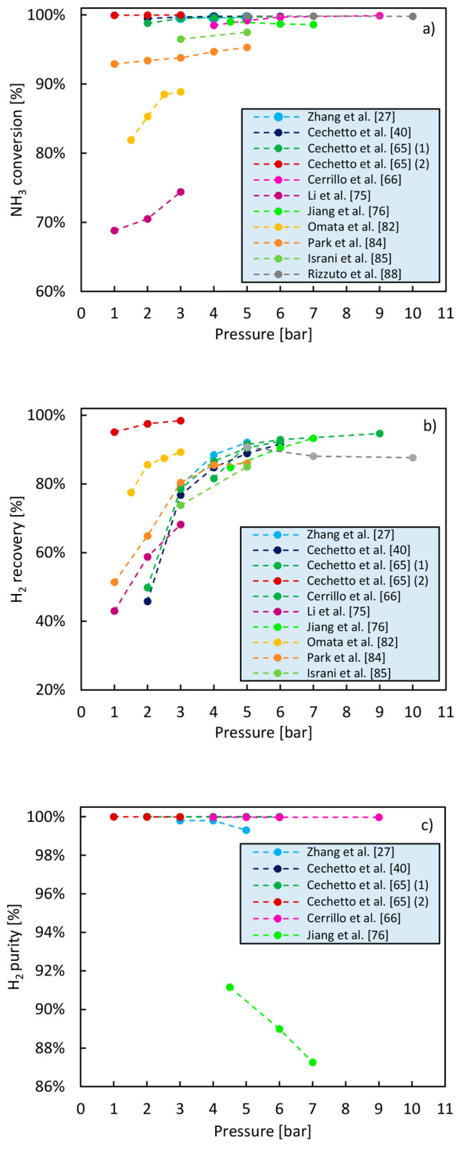
Effect of the ammonia decomposition reaction pressure on NH3 conversion (a), H2 recovery (b), and H2 purity (c) achieved in a membrane reactor. The data reported in this figure have been retrieved from studies available in the literature.
Table 5. Operating Conditions for Data in Figure 7.
| Author(s) [ref] | Temperature [°C] | Permeate pressure [bar] | NH3 flow rate [mLN/min] | Membrane selective layer composition | Catalyst |
|---|---|---|---|---|---|
| Zhang et al.27 | 500 | 1 | 200 | Pd | (Ni/Al = 1.20, La/Ni = 0.22) Ni/La-Al2O3, 6 g |
| Cechetto et al.40 | 500 | 1 | 500 | Pd-Ag | (2 wt %) Ru/Al2O3, 250 g |
| Cechetto et al.65 | 450 | 1) 1 | 500 | Pd-Ag | (2 wt %) Ru/Al2O3, 250 g |
| 2) 0.01 | |||||
| Cerrillo et al.66 | 485 | 1 | 200 | Pd-Au | (5 wt %) Ba-CoCe, 10 g |
| Li et al.76 | 450 | 0.5 | 40 | SiO2 | (0.45 wt %) Ru/γ-Al2O3/α-Al2O3, Ru impregnated in the membrane support |
| Jiang et al.77 | 450 | 1 | 10 | MFI zeolite | (3 wt %) Ru/Y/K/Al2O3, 1 g |
| Omata et al.83 | 350 | 1 | 10 | Pd-Ag/V-Fe | (5 wt %) Ru/Cs2O/Pr5O11, 0.2 g |
| Park et al.85 | 500 | 1 (100 mL/min of steam as sweep gas) | 100 | Pd/Ta/Pd | (0.65 wt %) Ru/(10 mol %) La-Al2O3, 1 g |
| Israni et al.86 | 500 | 1 | 126 | Pd | (70 wt %) Ni/γ-Al2O3, 29 g |
| Rizzuto et al.89 | 450 | 1 | 245 | Pd | (N/A) Ru/Al2O3, N/A |
All in all, the reactor operating pressure should be selected as a trade-off between the pressure allowing the maximization of hydrogen recovery and the one guaranteeing the targeted high hydrogen purity.
4.3.3. Effect of Permeate Pressure
Atmospheric pressure or vacuum conditions at the permeate side of the membrane allow one to minimize the partial pressure of hydrogen at the permeate side of the membrane, increasing the driving force for its separation. Cechetto et al.65 experimentally compared the performance of a membrane reactor for ammonia decomposition with the permeate at atmospheric conditions and the performance achieved upon vacuum application. It was demonstrated that the application of vacuum enhances the performance of the membrane reactor both in terms of conversion and hydrogen recovery. While performing ammonia decomposition at 400 °C, 4 bar, and under a feed flow rate of 500 mLN/min of pure ammonia, NH3 conversion in fact increased from 72.2% to 99.3% subsequent to vacuum application, while the thermodynamic equilibrium conversion for these specific operating conditions (without membrane) is calculated to be 96.7%. Itoh et al.,79,80 Kim et al.,82 and Li et al.76 also performed ammonia decomposition in a membrane reactor with the permeate side at vacuum conditions. The results achieved in these studies are summarized in Table 6.
Table 6. Overview of Performance Achieved When Operating a Membrane Reactor with the Permeate at Vacuum Conditions.
| Author(s) [ref] | Temperature [°C] | Reaction pressure [bar] | NH3 feed flow rate [mLN/min] | Space velocity [mLN/(gcat h)] | NH3 conversion [%] | H2 recovery [%] |
|---|---|---|---|---|---|---|
| Cechetto et al.65 | 400 | 4 | 500 | 120 | 99.3 | 93.5 |
| Li et al.76 | 400 | 1 | 10 | N/A | 84 | 77 |
| Itoh et al.79 | 450 | 1 | 10 | 1200 | 87a | 59a |
| Itoh et al.80 | 400 | 1 | 10 | 682 | 76a | N/A |
| Kim et al.82 | 430 | 5 | 950 | N/A | 99.4 | 97.5 |
Data not directly reported in the publication and retrieved from graphic representation of experimental results.
Pressurized hydrogen can be required for some applications, requiring the addition of a compression step to the process if hydrogen is produced at ambient or vacuum pressure. As a pressurized permeate would allow one to reduce or avoid this cost, Cerrillo et al.66 investigated the production of hydrogen from ammonia decomposition at a pressure higher than atmospheric. Specifically, they performed ammonia decomposition at 485 °C varying the pressure at the permeate side of the membrane from 1 to 15 bar, while increasing the pressure in the retentate chamber from 4 to 50 bar. The main experimental results of this study have been retrieved from their publication and are presented in Figure 8, in which NH3 conversion and H2 recovery are represented as a function of the ratio between the pressures at the retentate and permeate sides of the membrane, respectively. As expected, NH3 conversion and H2 recovery decrease with decreasing Pretentate/Ppermeate. This makes it clear that operating the reactor with a pressurized permeate is not really desirable when targeting the production of ultrapure (NH3-free) hydrogen. While this study might therefore not be relevant for PEMFC application as their optimal operating pressure typically lies between 3 and 4 bar,91 the results achieved in this work interestingly demonstrate that the membrane reactor for ammonia decomposition has a great degree of flexibility.
Figure 8.

Influence of permeate pressure for different retentate pressures on NH3 conversion (a) and H2 recovery (b). The experimental data presented in this figure have been retrieved from the work of Cerrillo et al.66 The experimental results have been obtained performing the decomposition of 200 mLN/min of pure ammonia at 485 °C on a catalyst bed consisting of 10 g of 0.5% Ba-CoCe diluted with 10 g of SiC.
4.3.4. Effect of NH3 Feed Flow Rate
The effect of NH3 feed flow rate on the membrane reactor performance is depicted in Figure 9 based on literature data. In Table 7, the operating conditions and the type of catalyst used in these works are reported. As ammonia feed flow rate increases, the residence time in the reactor decreases, and this results in lower NH3 conversion and lower hydrogen recovery. However, the produced hydrogen purity increases. These results show that high ammonia feed flow rates can be considered if high H2 purity at the outlet of the reactor is targeted. However, the recycle of unreacted NH3 and residual H2 in the retentate—or their possible integration as heat sources to sustain the endothermic system in the overall energy balance—should in this case be taken into account in the overall plant design.
Figure 9.

Effect of ammonia feed flow rate on NH3 conversion (a), H2 recovery (b), and H2 purity (c) achieved in a membrane reactor. The data reported in this figure have been retrieved from studies available in the literature.
Table 7. Operating Conditions for Data in Figure 9.
| Author(s) [ref] | Temperature [°C] | Reaction pressure [bar] | Permeate pressure [bar] | Membrane selective layer composition | Catalyst |
|---|---|---|---|---|---|
| Cechetto et al.40 | 500 | 5 | 1 | Pd-Ag | (2 wt %) Ru/Al2O3, 250 g |
| Cechetto et al.65 | 450 | 5 | 1 | Pd-Ag | (2 wt %) Ru/Al2O3, 250 g |
| Cerrillo et al.66 | 485 | 4 | 1 | Pd-Au | (0.5 wt %) Ba-CoCe, 10 g |
| Liu et al.67 | 425 | 3 | 1 | Pd/Pd-Ag | (5 wt %) Ru/MgO, 1.5 g |
| Jiang et al.77 | 450 | 7 | 1 | 1) Pd-Ag | 1) (3 wt %) Ru/Y/K/Al2O3, 3 g |
| 2) CMSM | 2) (3 wt %) Ru/Y/K/Al2O3, 3 g | ||||
| 3) MFI zeolite | 3) (3 wt %) Ru/Y/K/Al2O3, 1 g | ||||
| Itoh et al.79 | 450 | 1 | 0.01 | Pd | (5 wt %) Ru/SiO2, 0.5 g |
| Kim et al.82 | 430 | 5 | Vacuum | Pd | (2 wt %) Ru/Al2O3, N/A |
| Omata et al.83 | 350 | 3 | 1 | Pd-Ag/V-Fe | (5 wt %) Ru/Cs2O/Pr5O11, 0.2 g |
| Israni et al.86 | 500 | 5 | 1) 1 | Pd (nanopore) | (70 wt %) Ni/γ-Al2O3, 29 g |
| 2) Pd | |||||
| Sitar et al.87 | 450 | 5 | 1 | Pd | (0.5 wt %) Ru/Al2O3, 5 g in the catalyst bed |
| (1.9 wt %) Ru/YSZ, Ru impregnated in the membrane support | |||||
| Rizzuto et al.89 | 450 | 10 | 1 | Pd | Ru/Al2O3, N/A |
4.3.5. Efficient Membrane Reactors for Hydrogen Production from Ammonia Decomposition
In this section, the results that document the best performance achieved in membrane reactors for ammonia decomposition available in literature are shown. To this end, we define efficient membrane reactors as reactors in which a conversion of NH3 >99% and an H2 recovery >90% are simultaneously achieved. Accordingly, the results of the studies in which efficient membrane reactor operation was achieved are reported in Table 8. Next to the NH3 conversion and H2 recovery achieved, information on the reactor operating conditions and the catalyst and membrane used as well as on the volumetric hydrogen productivity and the total catalyst utilization is also reported. The volumetric hydrogen productivity and the total catalyst utilization, when not indicated in the publication, have been calculated from the properties and performance values of both the membrane and the reactor reported. Specifically, they have been calculated as the molar flow rate of hydrogen produced via ammonia decomposition in the membrane reactor per unit volume of the reactor and as the amount of catalyst in the reactor per unit volume of the membrane, respectively. Ammonia conversion >99% can be generally achieved at a nominally standard operating temperature of 450 °C and pressures between 5 and 7 bar if the reactor is operated with the permeate side of the membrane at atmospheric conditions using a Ru-based catalyst, whereas higher temperature is required with less active catalysts. Hydrogen recovery and hydrogen productivity are on the other hand dependent on the ammonia feed flow rate and on the membrane reactor separation performance. The best performance was achieved by Jiang et al.,77 who reported the highest volumetric productivity while efficiently using a highly active catalyst. The excellent performance of their system was achieved thanks to the use of both a highly efficient catalyst and a membrane with a low thickness for the selective layer (1.8 μm) which allowed for high hydrogen permeation. Despite a higher catalyst loading, Cechetto et al.65 achieved the lowest volumetric hydrogen productivity, which can be attributed to the reduced hydrogen permeance due to the high thickness of the membrane selective layer. Cerrillo et al.66 achieved the best performance in terms of catalyst utilization, but no information is available for the calculation of the volumetric hydrogen productivity achieved in their work. Given the high thickness of the membrane selective layer, we expect it however to be lower compared to the one achieved by Jiang et al.77
Table 8. Performance of Efficient Membrane Reactors (NH3 Conversion >99; H2 Recovery >90%) for Hydrogen Production from Ammonia Decomposition.
| Author(s) [ref] | Catalyst loading [wt %] (catalyst) | Membrane type and thickness [μm] | Temperature [°C] | Pressure [bar] | Pressure permeaten [bar] | NH3 conversion [%] | H2 recovery [%] | Volumetric productivity [mol m–3 s–1] | Total catalyst utilization [g/cm2] |
|---|---|---|---|---|---|---|---|---|---|
| Zhang et al.17 | 0.41 (Cs-Ru/YSZ) | Pd, 6.2 | 450 | 5 | 1 | >99 | – | 31.6 | N/A |
| Cechetto et al.40 | 2 (Ru/Al2O3) | Pd-Ag, 6–8 | 500 | 6 | 1 | 99.8 | 91.6 | 1.2a | 2.915a |
| Cechetto et al.65 | 2 (Ru/Al2O3) | Pd-Ag, 4.61 | 450 | 5 | 1 | 99.7 | 90.5 | 1.2a | 2.992a |
| 400 | 4 | Vacuum | 99.3 | 93.5 | 1.3a | 2.814a | |||
| Cerrillo et al.66 | 5 (Ba-CoCe) | Pd-Au, 8 | 485 | 5 | 1 | 99a | 91a | N/A | 0.143 |
| Jiang et al.77 | 3 (Ru-Y-K/Al2O3) | Pd-Ag, 1.8 | 450 | 7 | 1 | >99.1 | >90.6 | >40.8a | 0.168a |
| Kim et al.82 | 2 (Ru/Al2O3) | Pd, 5 | 430 | 5 | Vacuum | 99.4 | 97.5 | 1.5a | N/A |
| Sitar et al.87 | 1.9 (Ru/YSZ) | Pd, 4.23 | 450 | 5 | 1 | >99 | >90 | 54.2 | 0.221 |
| 0.5 (Ru/α-Al2O3) |
Not directly reported in the publication. Calculated based on provided membrane/reactor properties and performance values.
For completeness of this article, a summary of the performance achieved in all the articles that have been reviewed is reported in Table 9. The table includes information about the configuration of the membrane used for hydrogen separation, operating conditions of the membrane reactor, catalyst employed, and the best results achieved in each work. For best results, we consider the results that allowed the achievement of efficient membrane reactor operation (NH3 conversion >99% combined with H2 recovery >90%) or, when efficient reactor operation was not achieved, the results that were the closest to this target.
Table 9. NH3 Conversion and Corresponding Hydrogen Recovery Achieved in Membrane Reactors for Ammonia Decomposition Studies Available in Literature.
| Membrane |
Reactor
operating conditions |
NH3 conversion [%] |
||||||||||
|---|---|---|---|---|---|---|---|---|---|---|---|---|
| Author(s) [ref] | Membrane composition | Selective layer thickness [μm] | Length [mm] | Temperature [°C] | Reaction pressure [bar] | Permeate pressure [bar] | NH3 feed flow rate [mLN/min] | GHSV [mL/(gcat h)] | Catalyst | Conventional reactor | Membrane reactor | Hydrogen recovery [%] |
| Zhang et al.17 | Pd + Ru/YSZ | 6.2 | N/A | 400 | 5 | 1 | 30a | N/A | Ru (impregnated in the membrane support) | 31a | 93 | N/A |
| Ru-Cs/YSZ + Pd | 400 | 5 | 1 | 61.3 | N/A | N/A | 98 | 87.5 | ||||
| Zhang et al.27 | Pd + Al2O3 | 3 | N/A | 500 | 5 | 1 | 200b | 2000 | Ni/La-Al2O3 (Ni/Al = 1.20, La/Ni = 0.22), 6 g | 95a | >99a | 92a |
| Cechetto et al.40 | Al2O3-–YSZ + Pd-Ag + Al2O3 | ∼6–8 | 195 | 500 | 6 | 1 | 500 | 120b | (2 wt %) Ru/Al2O3, 250 g | N/A | 99.8 | 91.6 |
| Cechetto et al.65 | Al2O3-YSZ + Pd-Ag + Al2O3 | 4.61 | 202 | 400 | 4 | Vacuum | 500 | 120b | (2 wt %) Ru/Al2O3, 250 g | 65.4 | 99.3 | 93.5 |
| 190 | 450 | 5 | 1 | 500 | 120b | (2 wt %) Ru/Al2O3, 250 g | N/A | 99.7 | 90.5 | |||
| Cerrillo et al.66 | Pd-Au + ceramic support | 8 | 186a | 485 | 5 | 1 | 200 | 1200b | (0.5 wt %) Ba-CoCe, 10 g | N/A | >99a | 92a |
| Liu et al.67 | Pd + stainless steel support + MnCO3 | 6.5 | N/A | 400 | 3 | 1 | 47b | 1880 | (5 wt %) Ru/MgO, 1.5 g | N/A | 99.8 | N/A |
| Li et al.76 | Ru/γ-Al2O3/α-Al2O3+ SiO2 | <0.3 | N/A | 400 | 1 | Vacuum | 10 | N/A | (0.45 wt %) Ru/γ-Al2O3/α-Al2O3, Ru impregnated in the membrane support | 55 | 84 | 77 |
| Jiang et al.77 | Pd-Ag + Al2O3 | 1.8 | 100a | 450 | 7 | 1 | 250b | 5000 | (3 wt %) Ru/(1 wt %)Y/(12 wt %) K/Al2O3, 3 g | N/A | 99.11 | 90.6 |
| Itoh et al.79 | Pd | 200 | 65 | 450 | 1 | Vacuum | 9.7 | 1164b | (5 wt %) Ru/SiO2, 0.5 g | 73a | 87a | 59a |
| Itoh et al.80 | Pd + Al2O3 + Ru | 2 | 90 | 375 | 1 | Vacuum | 20 | N/A | (2 wt %) Ru/Al2O3, 0.88 g | 35a | >99a | N/A |
| Kim et al.82 | Pd + Inconel 600 | ∼5 | 450 | 430 | 5 | Vacuum | 950 | N/A | (2 wt %) Ru/Al2O3, N/A | N/A | 99.4 | 97.5 |
| Omata et al.83 | Pd-Ag + V-Fe | ∼0.2 μm Pd-Ag | N/A | 350 | 3 | 1 | 10 | 3000b | (5 wt %) Ru/Cs2O/Pr6O11, 0.2 g | 52.6%a | 89a | 89a |
| ∼100 μm V-Fe | ||||||||||||
| Jo et al.84 | Pd/Ta | ∼0.4 μm Pd | N/A | 450 | 6.5 | 1 | 3000b | 30000 | (1.6 wt %) Ru/La-Al2O3, 6 g | N/A | >99.5 | N/A |
| ∼250 μm Ta | ||||||||||||
| Park et al.85 | Pd/Ta/Pd | ∼1–2 μm Pd | N/A | 500 | 5 | 1 | 100b | 6000 | (0.65 wt %)Ru/(10 mol %)La-Al2O3, 1 g | N/A | 95a | 86a |
| ∼250 μm Ta | ||||||||||||
| Israni et al.86 | Pd/γ-Al2O3/α-Al2O3 | ∼13 | 156 | 500 | 3 | 1 | 65a | 135b | (70 wt %) Ni/γ-Al2O3, 29 g | N/A | 99a | 80a |
| Sitar et al.87 | Pd + Ru/YSZ | 4.23 | 73 | 450 | 5 | 1 | 100 | 1200b | (0.5 wt %) Ru/Al2O3, 5 g in the catalyst bed | N/A | >99a | >90a |
| (1.9 wt %) Ru/YSZ, Ru impregnated in the membrane support | ||||||||||||
| Rizzuto et al.89 | Pd + metallic support | N/A | N/A | 450 | 5 | 1 | 245 | N/A | (N/A) Ru/Al2O3, N/A | N/A | >99a | 91a |
Data not directly reported in the publication and retrieved from graphic representation of experimental results.
Data not directly reported in the publication. Calculated based on provided information about catalyst and flow rates used.
4.3.6. Hydrogen Purity and Residual Ammonia Traces
As previously mentioned, PEMFC specifications impose that hydrogen used as feedstock must contain a maximum residual NH3 concentration of 0.1 ppm. In case hydrogen is produced via ammonia decomposition, monitoring the purity of hydrogen produced and, particularly, its residual ammonia content is therefore paramount to prevent fuel cell electrodes poisoning. The experimental studies performed with membrane reactors for ammonia decomposition reporting information about the purity of hydrogen produced are compiled in Table 10, in which for each work the membrane reactor characteristics, the type of catalyst used, and the reaction conditions are reported next to the information regarding the purity of hydrogen produced and the residual ammonia concentration in the hydrogen stream. The best performances in terms of hydrogen purity have been achieved in membrane reactors implementing Pd-based membranes, and this is due to the fact that, compared to other type of membranes, Pd-based membranes show outstanding performance in terms of selectivity toward hydrogen separation.72,92 This was demonstrated by Jiang et al.77 who performed ammonia decomposition over a Ru/Y/K/Al2O3 catalyst and compared the performance of different types of membranes, namely, a modified MFI zeolite membrane, a carbon molecular sieve membrane, and a Pd-Ag membrane. While with all these membranes it was possible to obtain both NH3 conversion >99% and H2 recovery >90% under pressurized NH3 feed of 7 bar, the purity of hydrogen produced as well as the residual NH3 concentration in the hydrogen stream were demonstrated to be highly influenced by the different separation performances of the membranes. Hydrogen conforming to the ISO standard for fuel cell vehicle application—i.e., with ammonia and nitrogen concentrations less than 0.1 and 300 ppm, respectively—was produced when performing the decomposition of an ammonia feed flow rate ranging between 50 and 250 mL/min over 3 g of a Ru/Y/K/Al2O3 catalyst at 450 °C and with the the membrane reactor implementing a Pd-Ag membrane with a 1.8 μm thick selective layer. More specifically, by means of a gas chromatographer and an NH3 sensor for ammonia concentrations in the range between 10 ppb and 50 ppm, the N2 and NH3 concentrations in the hydrogen stream were measured to be below 0.01% and 10 ppb, respectively. On the other hand, when the reactor was equipped with a CMSM and with a modified MFI zeolite membrane, the poorer separation performance compared to the Pd-Ag membrane led to hydrogen purities <97% and <94%, respectively, which are therefore not compatible for a correct functioning of a PEMFC. Similarly, Omata et al.83 produced hydrogen conforming to the ISO standard for fuel cell vehicle application by performing the decomposition of 10 mL/min of pure ammonia over a Ru/Cs2O/Pr6O11 at 350 °C and 3 bar in a membrane reactor implementing a V-Fe/Pd-Ag membrane with a 100 μm thick V-Fe selective layer and 250 thick Pd-Ag selective layer. The residual ammonia concentration was estimated to be 0.06 ppm from the measurement carried out with an ion chromatograph on the amount of ammonium ion contained in 30 mL of a sulfuric acid aqueous solution bubbled with the hydrogen produced in the membrane reactor. Compared to the results achieved by Jiang et al.,77 in this work, fuel cell-grade hydrogen could be produced at significatively lower temperature. This has an advantage in terms of energy efficiency of the system. It is however worth noticing that the achievement of this result was only possible thanks to the use of a significantly thicker, thus more expensive, membrane.
Table 10. Studies Related to Ammonia Decomposition in Membrane Reactors Reporting the Purity of Hydrogen Produced and Residual Ammonia Concentration in the Hydrogen Stream.
| Membrane |
Reactor
operating conditions |
Hydrogen
purity |
||||||||||
|---|---|---|---|---|---|---|---|---|---|---|---|---|
| Author(s) [ref] | Selective layer composition | Selective layer thickness [μm] | Length [mm] | Temperature [°C] | Reaction pressure [bar] | Permeate pressure [bar] | NH3 feed flow rate [mLN/min] | GHSV [mL/(g–1cat h)] | Catalyst type | Maximum H2 purity [%] | NH3 concentration in the permeate [ppm] | Method used for NH3 concentration measurement |
| Zhang et al.17 | Pd | 6.2 | N/A | 450 | 5 | 1 | 100 | N/Aa | Cs (0.41 wt %) Ru/YSZ, Ru impregnated in the membrane support | >99.7 | <1000 | NDIR spectroscopy |
| Zhang et al.27 | Pd | ∼3 | N/A | 500 | 3 | 1 | 400 | 4000b | Ni/La-Al2O3 (Ni/Al = 1.20, La/Ni = 0.22), 6 g | >99.9a | N/A | N/A |
| Cechetto et al.40 | Pd-Ag | ∼6–8 | 195 | 500 | 2 | 1 | 500 | 120b | (2 wt %) Ru/Al2O3, 250 g | 99.998 | <0.75 | FTIR spectroscopy |
| Cechetto et al.65 | Pd-Ag | 4.61 | 202 | 450 | 1 | Vacuum | 500 | 120b | (2 wt %) Ru/Al2O3, 250 g | 99.995 | 2.91 | FTIR spectroscopy |
| Cerrillo et al.66 | Pd-Au | 8 | N/A | 350–500 | 4–15 | 1 | 100–310 | 600–1870b | (0.5 wt %) Ba-CoCe, 10 g | 99.97 ± 0.03 | N/A | Gas chromatography |
| Liu et al.67 | Pd/Pd-Ag | 6.5 | N/A | 400 | 3 | 1 | 47 | 1880b | (5 wt %) Ru/MgO, 1.5 g | 99.85a | N/A | N/A |
| Li et al.76 | SiO2 | <0.3 | N/A | 400 | 1 | Vacuum | 10 | N/A | (0.45 wt %) Ru/γ-Al2O3/α-Al2O3, Ru impregnated in the membrane support | 84.0 | 45,000 | Gas chromatography |
| Jiang et al.77 | MFI zeolite | 8 | N/A | 450 | 4.5 | 1 | 10 | 600 | (3 wt %) Ru/(1 wt %) Y/(12 wt %) K/Al2O3, 3 g | 91.16 | 3500 | Gas chromatography |
| CMSM | 0.9 | 220 | 450 | 7 | 1 | 250 | 5000 | 96.84 | <10,000 | Gas chromatography and NH3 sensor | ||
| Pd-Ag | 1.8 | 80 | 450 | 7 | 1 | 50–250b | 1000–5000 | >99.999 | <0.01 | |||
| Omata et al.83 | Pd-Ag/V-Fe | 0.2/100 | N/A | 350 | 3 | Vacuum | 10 | 3000b | (5 wt %) Ru/Cs2O/Pr6O11, 0.2 g | <99.9975 | <0.06 | Ion chromatography |
| Jo et al.84 | Pd/Ta | ∼0.4 μm Pd | N/A | 450 | 6.5 | 1 | 3000b | 30000 | (1.6 wt %) Ru/La-Al2O3, 6 g | >99.9999 | 0.8 | Tunable diode laser spectrometry |
| ∼250 μm Ta | ||||||||||||
| Park et al.85 | Pd/Ta/Pa | ∼1–2 | 76 | 425 | 3 | 1 | 20b | 1200 | (0.65 wt %) Ru/(10 mol %)La-Al2O3, 1 g | N/A | 4.2 | IR spectroscopy |
| Sitar et al.87 | Pd | 4.23 | 73 | 450 | 5 | 1 | 100–300 | 1200–3600b | (0.5 wt %) Ru/Al2O3, 5 g in the catalyst bed | N/A | 650a | Draeger tube |
| (1.9 wt %) Ru/YSZ (Ru impregnated in the membrane support) | ||||||||||||
Data not directly reported in the publication and retrieved from graphic representation of experimental results.
Data not directly reported in the publication. Calculated based on provided information about catalyst and flow rates used.
In other works, despite a purity of hydrogen higher than 99% being achieved, the compliance with the residual NH3 limit imposed by the specifications on PEMFCs was challenging. Cechetto et al.,65 for instance, while obtaining a purity of hydrogen of 99.995% measured the concentration of NH3 in the stream to be 2.9 ppm through FTIR measurements. This result was achieved at 450 °C, with a pressure difference across the membrane of 1 bar, under a feed flow rate of 500 mLN/min and with a membrane with a 4.61 μm thick selective layer. In a follow up work, Cechetto et al.40 demonstrated that a targeted hydrogen purity can be achieved by properly tuning the reactor operating conditions as well as increasing the thickness of the membrane selective layer. Under a similar pressure difference across the membrane and NH3 feed flow rate compared to their previous work, Cechetto et al. demonstrated the production of 99.998% pure hydrogen containing an NH3 concentration lower than the FTIR accuracy limit of 0.75 ppm at 500 °C with a membrane having an ∼6–8 μm thick selective layer. Cerrillo et al.66 performed ammonia decomposition over a Co-based catalyst in a packed bed membrane reactor using a Pd-Au alloy membrane with 8 μm thick selective layer and achieved purities higher than 99.97 ± 0.03% for temperature ranging between 350 and 500 °C, pressures between 4 and 15 bar, and a NH3 feed flow rate ranging between 100 and 310 mLN/min of pure ammonia. Moreover, Cerrillo et al.66 report that the hydrogen produced in this system is NH3 free and could therefore directly be used as feedstock for PEMFCs. While this seems to be a very promising result, the authors report that residual ammonia concentrations were measured by means of a micro-GC of which however the detection limits are unknown.
As is possible to see from Table 10, in most of the works, the purity of hydrogen produced did not meet the requirements for fuel cell application. However, while hydrogen produced in these works is not suitable to be directly used as fuel for such devices, it could be still used for this purpose if a hydrogen purification stage would be introduced between the membrane reactor and the PEMFC. Several studies available in the literature demonstrate in fact that the purification of hydrogen from residual ammonia can be carried out by means of commercially available NH3 sorbents as well as by means of zeolites.44−47,93 Sitar et al.87 experimentally demonstrated that the residual ammonia impurities in the hydrogen stream can be reduced from ∼1000 ppm to values below 0.025 ppm using the earth-abundant zeolite clinoptilolite as adsorbent material for ammonia removal. The measure of such low NH3 concentrations was determined by analyzing the position of the reaction front and the volume of gas passing through Draeger tubes packed with a yellow adsorbent material that irreversibly turns purple upon ammonia exposure. In agreement with the results of this study, Cechetto et al.40 experimentally demonstrated that with the addition of a hydrogen purification unit consisting of a bed of zeolite 13X at ambient conditions it is possible to produce hydrogen with residual ammonia concentration below 0.75 ppm even at 450 °C and using a membrane with an ∼1 μm thick selective layer. Although this solution makes the system more complex, the benefits introduced in the system are such that this solution might be regarded as the most favorable both from an economic and an energy point of view. The introduction of a hydrogen purification stage offers in fact the possibility to produce ultrapure hydrogen while adopting a lower reactor temperature as well as thinner membranes, lowering energy consumption and costs.
Li et al.76 performed ammonia decomposition in a silica-based catalytic membrane reactor and reported that at 400 °C and under a NH3 feed flow rate of 10 mL/min the purity and the NH3 concentration in the permeate stream were 84.0% and 4.5%, respectively. While these results suggest that the purity of hydrogen achieved with this type of reactor is significantly lower compared to the purity achievable in a Pd-based membrane reactor and not sufficiently high for direct hydrogen utilization in PEMFC, the authors believe that that the advantages of a silica-based catalytic membrane reactor may compensate for the fact that in order to obtain fuel cell-grade hydrogen a hydrogen purification unit downstream the reactor should be implemented increasing the system complexity.
Kim et al.82 investigated hydrogen production by ammonia decomposition over a Ru/Al2O3 catalyst using a Pd-based membrane on porous metallic support with a selective layer thickness of ∼1 μm. While they report that at 472 °C, 5 bar, NH3 feed flow rate of 2840 mL/min, and with the permeate side of the membrane at vacuum conditions the production of 99.99% pure hydrogen could be achieved, the purity of hydrogen was measured through gas chromatography downstream a water trap and a cold trap that served to eliminate the residual traces of ammonia in the stream.
Finally, Jo et al.84 and Park et al.85 investigated a membrane reactor for hydrogen production from ammonia decomposition integrated with a PEMFC. In both these works, despite containing traces of ammonia, the hydrogen produced via ammonia decomposition in the membrane reactor was fed to a PEMFC, and in the work of Jo et al.,84 no degradation of the device was observed for an extended time of operation. Jo et al. demonstrated that performing ammonia decomposition over a Ru/La-Al2O3 catalyst in a packed bed membrane reactor using a dense metallic Pd/Ta composite membrane with a 0.4 μm thick Pd selective layer and 250 μm thick Ta selective layer it is possible to produce hydrogen with purities higher than 99.9999% and residual ammonia concentration of 0.8 ppm (measured by Nessler method) when working at 450 °C, 6.5 bar, and with an ammonia feed flow rate of 30,000 mL/g–1cat h–1. Park et al.85 produced hydrogen containing a residual ammonia concentration of 4.2 ppm (measured by Nessler method) while performing ammonia decomposition at 425 °C, 3 bar, and with an ammonia feed flow rate of 1200 mL/g–1cat h–1 in a membrane reactor coupling a custom developed Pd/Ta composite metallic membrane and a ruthenium on lanthanum-doped alumina catalyst (Ru (0.65 wt. %)/La (10 mol. %)-Al2O3). In both works, steam was adopted as the sweep gas allowing for separation of pure hydrogen upon its condensation. The condensed water could be subsequently recirculated in the system prior to vaporization exploiting the waste heat from the system and serve as an NH3 scrubber in the hydrogen stream. Park et al.85 demonstrated that the amount of ammonia in the permeated hydrogen could be reduced from 4.2 to 1.8 ppm after flowing the hydrogen stream through a gas–liquid separator containing 300 cm3 of bubbling DI water.
5. Membrane Reactor for Ammonia Decomposition in Diluted Streams
Even though this review focuses on the production of PEM fuel cell-grade hydrogen from pure ammonia, for the sake of completeness, in this section, we report the works that have investigated the use of a membrane reactor for ammonia decomposition as cleaning technology in diluted NH3 streams.
As a matter of fact, the earliest studies on membrane reactors for ammonia decomposition addressed the gas cleaning of streams containing NH3 traces. Collins et al.,94 for example, suggested the use of a membrane reactor as a strategy to reduce the trace amount of ammonia from coal gasification processes which are responsible for nitrogen oxide (NOx) emissions and experimentally investigated the potential of this technology using a simplified gas composition of H2, N2, and NH3 in typical concentrations of an integrated gasification combined cycle (IGCC) synthesis. A composite palladium-ceramic membrane with thickness of the selective layer of 11.4 μm and 55 mm active lengths and a supported Ni/Al2O3 catalyst were used for hydrogen separation and as the catalyst, respectively. It was demonstrated that the membrane reactor can significantly improve ammonia conversion when diluted concentrations of ammonia and high concentrations of hydrogen and nitrogen are fed to the membrane reactor. Similarly, other studies investigated NH3 decomposition in membrane reactors considering feed streams in which ammonia is very diluted, such as purge streams from ammonia production plants or synthesis gas streams from coal gasification plants.95−100 Although interesting from a fundamental perspective, these studies investigate ammonia decomposition at different operating conditions and reaction kinetics compared to the ones in which ammonia is regarded as a hydrogen carrier for hydrogen production for PEM fuel cell applications, and their results are thus not extensively reviewed in this article.
Moreover, we chose not to include in this review article the results of studies in which nitrogen, helium, or other noble gases have been used at the permeate side of the membrane as sweep gases.25,88,101 In fact, while the use of a sweep gas favors hydrogen recovery, the hydrogen produced with this technique is diluted and therefore not interesting for pure hydrogen production purposes. Articles in which steam has been use as the sweep gas85 are on the other hand reviewed, since although apparently diluting the produced hydrogen stream, steam can be easily separated from hydrogen via condensation resulting in the production of pure hydrogen. A summary of experimental results available in the literature on membrane reactors for ammonia decomposition using diluted streams as feed and/or sweep gas at the permeate side of the membrane is presented in Table 11.
Table 11. Summary of Literature Available on Experimental Studies on Membrane Reactors for Decomposition of Ammonia Available in Diluted Streams or Sweep Gas.
| Membrane |
Reactor operating conditions |
||||||||||||
|---|---|---|---|---|---|---|---|---|---|---|---|---|---|
| Author(s) [ref] | Configuration | Selective layer composition | Selective layer thickness [μm] | Length [mm] | Temperature [°C] | Reaction pressure [bar] | Permeate pressure [bar] | Feed [mLN/min] | Feed composition [mol %] | Sweep gas flow rate [mL/min] | Catalyst type | Highest NH3 conversion [%] | Hydrogen recovery [%] |
| Li et al.25 | Silica membrane on bimodal catalytic support (Ru/γ-Al2O3/α-Al2O3) | SiO2 | <0.0003 | N/A | 450 | 1 | 1 | 10 | 100 (NH3) | 100 (N2) | Ru | 94.3 | 93a |
| Li et al.88 | Silica membrane on bimodal catalytic support (Ru/γ-Al2O3/α-Al2O3) | SiO2 | <0.0003 | N/A | 390–470 | 1 | 1 | 10–50 | 100 (NH3) | 10–100 (N2) | Ru | 96a | 91a |
| Collins et al.94 | Supported composite Pd-ceramic membranes | Pd | 11.4 | 55 | 450–600a | 16.18 | 1 | 435 | 48 (N2) | N/A | Ni/Al2O3 | >94 | N/A |
| 20 (H2) | |||||||||||||
| 31.665 (He) | |||||||||||||
| 0.335 (NH3) | |||||||||||||
| García-García et al.95 | Pd/porous stainless steel composite membrane | Pd | 40 | N/A | 333–592a | 1 | 1 | 100 | 90 (He) | 100–300 (He) | Carbon supported Ru-based catalyst promoted with sodium (2 wt % Ru) | 100 | N/A |
| 10 (NH3) | |||||||||||||
| Cheng et al.101 | Dual layer NMW/NMW-Ni hollow fiber membrane | Nd5.5Mo0.5W0.5O11.25-δ (NMW) | 26 | N/A | 600–750 | 1 | 1 | 50 | 60–80 mol % He | 50 mL/min N2 | NMW-NiO catalytic support of the membrane (0.11 g) | 99 | N/A |
| 20–40 mol % NH3 | |||||||||||||
Data not directly reported in the publication and retrieved from graphic representation of experimental results.
6. Challenges and Perspectives
Storing hydrogen in the form of liquid ammonia offers a promising solution to the current obstacles associated with physical storage and distribution of hydrogen, which hinder the progress of the hydrogen economy. Additionally, due to its lack of carbon emissions, ammonia could serve as a cleaner substitute for fossil fuels, playing a crucial role in the decarbonization of the current energy system. Nevertheless, the implementation of an ammonia-based energy system necessitates further research to tackle numerous challenges, spanning the entire value chain of ammonia production, distribution, and application.
First, ammonia can be regarded as a cost-effective CO2-free energy and hydrogen carrier only under the assumption that ammonia production and utilization processes are powered by renewable energy and do not imply direct or indirect CO2 emissions.31 Future research needs therefore to be addressed in the attempt to decarbonize the ammonia production step as at the moment more than 90% of the global production of ammonia are carried out in the conventional Haber–Bosch process.102 The Haber–Bosch process produces ammonia at relatively high temperatures and pressures in the ranges of 400–500 °C and 10–30 MPa, with an energy consumption ranging between 28 to 37 GJ/tNH3.103 Moreover, since it generally uses as feedstock for ammonia synthesis hydrogen produced from fossil fuels (coal, natural gas, naphtha, or oil), the ammonia production process is responsible for carbon dioxide emissions ranging between 2.0 and 4.6 tCO2/tNH3,104 for a total annual emission of about 400 MtCO2, which represents around 1.5% of all greenhouse gas emissions.102 The decarbonization of this process should therefore tackle several challenges among which are the production of green ammonia with a cost competitive to fossil fuel-derived ammonia and the design of a system capable of being flexible enough to follow the fluctuations and intermittency of renewable electricity sources.105 Pursuing this mission, Hydrogen Utility (H2U) in partnership with ThyssenKrupp has developed The Port Lincoln Hydrogen Energy Storage System (Eyre Peninsula, South Australia, Australia), one of the first commercial plants capable of producing green ammonia from intermittent energy resources. This demonstration plant includes a 30 MW water electrolysis plant, an ammonia production facility with a capacity of 50 tons per day, and two 16 MW open-cycle turbines operating 100% on hydrogen at the site to provide electricity to the grid during periods of low wind or solar output.106 While H2U expects to sell the relatively small amount of green ammonia produced in this facility into the local agriculture market as fertilizer, this plant will demonstrate the techno-economic viability of the novel supply chain technology of green hydrogen in the form of ammonia.106
Other major obstacles toward the deployment of ammonia-based energy systems are then mainly related to the hydrogen production and purification steps through ammonia decomposition. Hydrogen production from ammonia is in fact an energy intensive process; thus, research into materials, technologies, and possible plant configurations is essential to achieve high energy efficiencies in the utilization of ammonia at different scales. Particularly, one of the main challenges consists of the development of a new generation of catalysts to replace the Ru-based ones, which while leading at the moment the highest reaction rate and the lowest temperature are on the other hand extremely expensive. The formulation of new catalysts should therefore target the reduction of the ammonia decomposition temperature as well as the use of readily available, non-noble materials, ensuring the reduction of both the operational and capital expenditures of the system, respectively. As far as the materials and technologies for hydrogen purification from ammonia are concerned, relatively inexpensive commercial adsorbent materials and water absorption units have been demonstrated to be effective, with little need for new technologies and materials development. Nevertheless, it is crucial to use accurate instruments with adequate detection limits to measure the purity of hydrogen produced, particularly for PEM fuel cell applications that require extremely low residual ammonia concentration. Similarly, precise analytical instrumentation should be used to measure the ammonia concentration in the hydrogen stream at the permeate side of membrane reactors, especially in situations in which the selectivity of membranes is high enough to potentially produce fuel cell-grade hydrogen without downstream hydrogen purification. Research on materials should finally explore new routes for the fabrication of economically competitive membranes with high selectivity toward hydrogen. Current literature suggests that Pd-based membranes can achieve a H2/N2 selectivity sufficiently high to eliminate the need for a N2 separation unit in the system, even in systems for hydrogen production for vehicle applications. However, the high investment cost associated with Pd-based membranes has to be assessed and necessitates the development of cheaper formulations capable of providing comparable separation properties comparable.
An additional technical aspect worthy of attention pertains to the mode of heat generation which is required to sustain the ammonia decomposition reaction. To promote the development of a sustainable and environmentally friendly energy system, heating powered by renewables or green fuels should be preferred over conventional carbon-based fuels. The direct combustion of ammonia is economically favorable, but involves the generation of a significant amount of harmful nitrogen oxides (NOx). Selective catalytic reduction (SCR) or selective noncatalytic reduction (SNCR) processes, as well as stoichiometric controlled oxidation (SCO) technology, can be used to achieve in a single unit both complete NH3 combustion and limited NOx formation.
While in the literature it has been demonstrated that from a technical point of view the production of fuel cell-grade hydrogen in a membrane reactor-based system is possible regardless of the type of membrane when using a hydrogen purification stage downstream the membrane reactor, very little information is available regarding the economic feasibility of the system. Yet, some studies calculated the costs of hydrogen production from ammonia decomposition,31,39 but to the best of our knowledge, a comparative study addressing a techno-economic assessment at different plant capacities and configurations is not available. Additional work should therefore investigate the techno-economic feasibility of an NH3-to-H2 system, identifying the design choices and plant capacities that make a membrane reactor-based system more competitive compared to a conventional system. Techno-economic feasibility studies should investigate both centralized plants in which hydrogen is produced in large quantities remotely and is subsequently transported to the point of end use, as well as decentralized scenarios in which hydrogen is produced using smaller-scale production systems to supply local demand. The difference in plant capacity as well as in the location relative to the end point of use of hydrogen have in fact an impact on the final cost of the technology which varies on a case-by-case basis.
7. Conclusions
In this review article, we have reported the latest developments in membrane reactors for hydrogen production from ammonia decomposition, especially looking at operating conditions, membrane properties, and possible downstream separation/purification units. All works report remarkable improvements in terms of hydrogen production and ammonia conversion compared to conventional systems, and the following few general considerations can be drawn:
Membrane reactors allow working at lower temperatures and higher pressures compared to conventional systems with an increase of energy efficiency. Ammonia is transported as liquid at higher pressures (>8 bar at least), and this means that high pressure can be easily used in membrane reactors to achieve high conversion at a limited membrane area. Ideally, the membrane reactor should be operated at the same pressure of the ammonia storage to avoid additional compressions in between.
As the membrane reactor can work at lower temperatures compared to conventional systems, temperatures below 500 °C are preferable. By optimizing catalysts and membrane flux (and increasing the installed membrane area), the reactor could even be operated at temperatures lower than 400 °C, which would allow easier heat integration of the reactor with the upstream and downstream apparatuses.
The very important parameters to be optimized in the ammonia decomposition unit are hydrogen recovery and hydrogen purity, while conversions lower than 100% are not a problem as the retentate stream can be used to generate the energy required for the vaporization of the feed and the heating of the reactor.
According to the literature, the best performing membranes seem to be Pd-based ones. However, fuel cell-grade hydrogen could only be achieved with relatively thick membranes. On the other hand, the latest results also show that relatively inexpensive sorption units downstream of the membrane reactor can allow to easily achieve fuel cell-grade hydrogen production (containing NH3 concentration <0.1 ppm, for the detection of which, dedicated and accurate analytical systems are key). These results show that fuel cell-grade hydrogen can also be produced working with thinner membranes, thus improving the CAPEX of the system, or even using much less expensive membranes such as ceramic or carbon membranes.
Biographies
Valentina Cechetto holds a BSc. degree and a MSc. degree in energy engineering with specialization in power production from Politecnico di Milano. She also received an Engineering Doctorate (EngD) in process and product design from the Eindhoven University of Technology. Currently, she is enrolled as a Ph.D candidate in the Sustainable Process Engineering group at the Eindhoven University of Technology. Her research focuses on the development of membrane reactors for hydrogen production from green ammonia.
Dr. Luca Di Felice holds a double Ph.D. in chemical engineer and catalysis from the University of Strasbourg (France) and L’Aquila (Italy). He is currently a researcher at the Eindhoven University of Technology. His research encompasses heterogeneous catalysis and sorbents development as well as membrane reactors and their efficient integration.
The research of Prof. Fausto Gallucci at the Inorganic Membranes and Membrane Reactors research group is related to the development of membranes and novel multiphase reactors, in particular membrane reactors and dynamically operated reactors. His research focuses on the interaction of heterogeneous catalysis, transport phenomena, and fluid mechanics in these novel multifunctional reactors. Particularly interesting are CO2 hydrogenation in carbon membranes, methane activation with oxygen membranes, and hydrogen production with hydrogen selective membranes.
Author Contributions
The manuscript was written through contributions of all authors. All authors have given approval to the final version of the manuscript.
This project receives support from the European Union’s Horizon 2020 Research and Innovation under Grant Agreement No. 862482 (ARENHA project).
The present publication reflects only the author’s views and the Commission is not responsible for any use that may be made of the information it contains.
The authors declare no competing financial interest.
References
- Valera-Medina A.; Xiao H.; Owen-Jones M.; David W. I. F.; Bowen P. J. Ammonia for Power. Prog. Energy Combust. Sci. 2018, 69, 63–102. 10.1016/j.pecs.2018.07.001. [DOI] [Google Scholar]
- Höök M.; Tang X. Depletion of Fossil Fuels and Anthropogenic Climate Change—A Review. Energy Policy 2013, 52, 797–809. 10.1016/j.enpol.2012.10.046. [DOI] [Google Scholar]
- World Energy Outlook 2022; IEA: Paris, 2022. [Google Scholar]
- Valera-Medina A.; Amer-Hatem F.; Azad A. K.; Dedoussi I. C.; de Joannon M.; Fernandes R. X.; Glarborg P.; Hashemi H.; He X.; Mashruk S.; McGowan J.; Mounaim-Rouselle C.; Ortiz-Prado A.; Ortiz-Valera A.; Rossetti I.; Shu B.; Yehia M.; Xiao H.; Costa M. Review on Ammonia as a Potential Fuel: From Synthesis to Economics. Energy Fuels 2021, 35 (9), 6964–7029. 10.1021/acs.energyfuels.0c03685. [DOI] [Google Scholar]
- Veziroğlu T. N.; Şah’n S. 21st Century’s Energy: Hydrogen Energy System. Energy Convers Manag 2008, 49 (7), 1820–1831. 10.1016/j.enconman.2007.08.015. [DOI] [Google Scholar]
- Notton G.; Nivet M.-L.; Voyant C.; Paoli C.; Darras C.; Motte F.; Fouilloy A. Intermittent and Stochastic Character of Renewable Energy Sources: Consequences, Cost of Intermittence and Benefit of Forecasting. Renewable and Sustainable Energy Reviews 2018, 87, 96–105. 10.1016/j.rser.2018.02.007. [DOI] [Google Scholar]
- Andersson J.; Grönkvist S. Large-Scale Storage of Hydrogen. Int. J. Hydrogen Energy 2019, 44 (23), 11901–11919. 10.1016/j.ijhydene.2019.03.063. [DOI] [Google Scholar]
- Ausfelder F.; Beilmann C.; Bertau M.; Bräuninger S.; Heinzel A.; Hoer R.; Koch W.; Mahlendorf F.; Metzelthin A.; Peuckert M.; Plass L.; Räuchle K.; Reuter M.; Schaub G.; Schiebahn S.; Schwab E.; Schüth F.; Stolten D.; Teßmer G.; Wagemann K.; Ziegahn K.-F. Energy Storage as Part of a Secure Energy Supply. ChemBioEng. Reviews 2017, 4 (3), 144–210. 10.1002/cben.201700004. [DOI] [Google Scholar]
- Dell R. M.; Bridger N. J. Hydrogen—The Ultimate Fuel. Appl. Energy 1975, 1 (4), 279–292. 10.1016/0306-2619(75)90029-X. [DOI] [Google Scholar]
- Rosen M. A.; Koohi-Fayegh S. The Prospects for Hydrogen as an Energy Carrier: An Overview of Hydrogen Energy and Hydrogen Energy Systems. Energy Ecol Environ 2016, 1 (1), 10–29. 10.1007/s40974-016-0005-z. [DOI] [Google Scholar]
- Abe J. O.; Popoola A. P. I.; Ajenifuja E.; Popoola O. M. Hydrogen Energy, Economy and Storage: Review and Recommendation. Int. J. Hydrogen Energy 2019, 44 (29), 15072–15086. 10.1016/j.ijhydene.2019.04.068. [DOI] [Google Scholar]
- Bockris J. O. M. The Hydrogen Economy: Its History. Int. J. Hydrogen Energy 2013, 38 (6), 2579–2588. 10.1016/j.ijhydene.2012.12.026. [DOI] [Google Scholar]
- Johnston B.; Mayo M. C.; Khare A. Hydrogen: The Energy Source for the 21st Century. Technovation 2005, 25 (6), 569–585. 10.1016/j.technovation.2003.11.005. [DOI] [Google Scholar]
- Yin S. F.; Xu B. Q.; Zhou X. P.; Au C. T. A Mini-Review on Ammonia Decomposition Catalysts for on-Site Generation of Hydrogen for Fuel Cell Applications. Appl. Catal. A Gen 2004, 277 (1), 1–9. 10.1016/j.apcata.2004.09.020. [DOI] [Google Scholar]
- Lemmon E. W.; Bell I. H.; Huber M. L.; McLinden M. O.. NIST Standard Reference Database 23: Reference Fluid Thermodynamic and Transport Properties-REFPROP, Version 10.0; National Institute of Standards and Technology, 2013. 10.18434/T4/1502528. [DOI]
- Jensen J. O.; Vestbø A. P.; Li Q.; Bjerrum N. J. The Energy Efficiency of Onboard Hydrogen Storage. J. Alloys Compd. 2007, 446–447, 723–728. 10.1016/j.jallcom.2007.04.051. [DOI] [Google Scholar]
- Zhang Z.; Liguori S.; Fuerst T. F.; Way J. D.; Wolden C. A. Efficient Ammonia Decomposition in a Catalytic Membrane Reactor to Enable Hydrogen Storage and Utilization. ACS Sustain Chem. Eng. 2019, 7 (6), 5975–5985. 10.1021/acssuschemeng.8b06065. [DOI] [Google Scholar]
- Lan R.; Irvine J. T. S.; Tao S. Ammonia and Related Chemicals as Potential Indirect Hydrogen Storage Materials. Int. J. Hydrogen Energy 2012, 37 (2), 1482–1494. 10.1016/j.ijhydene.2011.10.004. [DOI] [Google Scholar]
- Sordakis K.; Tang C.; Vogt L. K.; Junge H.; Dyson P. J.; Beller M.; Laurenczy G. Homogeneous Catalysis for Sustainable Hydrogen Storage in Formic Acid and Alcohols. Chem. Rev. 2018, 118 (2), 372–433. 10.1021/acs.chemrev.7b00182. [DOI] [PubMed] [Google Scholar]
- Klerke A.; Christensen C.; Nørskov J.; Vegge T. Ammonia for Hydrogen Storage: Challenges and Opportunities. J. Mater. Chem. 2008, 18, 2304–2310. 10.1039/b720020j. [DOI] [Google Scholar]
- Eppinger J.; Huang K.-W. Formic Acid as a Hydrogen Energy Carrier. ACS Energy Lett. 2017, 2 (1), 188–195. 10.1021/acsenergylett.6b00574. [DOI] [Google Scholar]
- Lan R.; Tao S. Ammonia as a Suitable Fuel for Fuel Cells. Front Energy Res. 2014, 2, na. 10.3389/fenrg.2014.00035. [DOI] [Google Scholar]
- Lamb K. E.; Dolan M. D.; Kennedy D. F. Ammonia for Hydrogen Storage; A Review of Catalytic Ammonia Decomposition and Hydrogen Separation and Purification. Int. J. Hydrogen Energy 2019, 44 (7), 3580–3593. 10.1016/j.ijhydene.2018.12.024. [DOI] [Google Scholar]
- Cha J.; Jo Y. S.; Jeong H.; Han J.; Nam S. W.; Song K. H.; Yoon C. W. Ammonia as an Efficient COX-Free Hydrogen Carrier: Fundamentals and Feasibility Analyses for Fuel Cell Applications. Appl. Energy 2018, 224, 194–204. 10.1016/j.apenergy.2018.04.100. [DOI] [Google Scholar]
- Li G.; Kanezashi M.; Tsuru T. Highly Enhanced Ammonia Decomposition in a Bimodal Catalytic Membrane Reactor for COx-Free Hydrogen Production. Catal. Commun. 2011, 15 (1), 60–63. 10.1016/j.catcom.2011.08.011. [DOI] [Google Scholar]
- Sørensen R. Z.; Nielsen L. J. E.; Jensen S.; Hansen O.; Johannessen T.; Quaade U.; Christensen C. H. Catalytic Ammonia Decomposition: Miniaturized Production of COx-Free Hydrogen for Fuel Cells. Catal. Commun. 2005, 6 (3), 229–232. 10.1016/j.catcom.2005.01.005. [DOI] [Google Scholar]
- Zhang J.; Xu H.; Li W. High-Purity COx-Free H2 Generation from NH3 via the Ultra Permeable and Highly Selective Pd Membranes. J. Membr. Sci. 2006, 277 (1), 85–93. 10.1016/j.memsci.2005.10.014. [DOI] [Google Scholar]
- Chellappa A. S.; Fischer C. M.; Thomson W. J. Ammonia Decomposition Kinetics over Ni-Pt/Al2O3 for PEM Fuel Cell Applications. Appl. Catal. A Gen 2002, 227 (1), 231–240. 10.1016/S0926-860X(01)00941-3. [DOI] [Google Scholar]
- Le T. A.; Kim Y.; Kim H. W.; Lee S.-U.; Kim J.-R.; Kim T.-W.; Lee Y.-J.; Chae H.-J. Ru-Supported Lanthania-Ceria Composite as an Efficient Catalyst for COx-Free H2 Production from Ammonia Decomposition. Appl. Catal., B 2021, 285, 119831. 10.1016/j.apcatb.2020.119831. [DOI] [Google Scholar]
- Staffell I.; Scamman D.; Velazquez Abad A.; Balcombe P.; Dodds P. E.; Ekins P.; Shah N.; Ward K. R. The Role of Hydrogen and Fuel Cells in the Global Energy System. Energy Environ. Sci. 2019, 12 (2), 463–491. 10.1039/C8EE01157E. [DOI] [Google Scholar]
- Makhloufi C.; Kezibri N. Large-Scale Decomposition of Green Ammonia for Pure Hydrogen Production. Int. J. Hydrogen Energy 2021, 46 (70), 34777–34787. 10.1016/j.ijhydene.2021.07.188. [DOI] [Google Scholar]
- Why ammonia is the more efficient hydrogen carrier. ThyssenKrupp. https://www.thyssenkrupp.com/en/stories/sustainability-and-climate-protection/why-ammonia-is-the-more-efficient-hydrogen-carrier.
- Morlanés N.; Katikaneni S. P.; Paglieri S. N.; Harale A.; Solami B.; Sarathy S. M.; Gascon J. A Technological Roadmap to the Ammonia Energy Economy: Current State and Missing Technologies. Chemical Engineering Journal 2021, 408, 127310. 10.1016/j.cej.2020.127310. [DOI] [Google Scholar]
- Gallucci F.; Fernandez E.; Corengia P.; van Sint Annaland M. Recent Advances on Membranes and Membrane Reactors for Hydrogen Production. Chem. Eng. Sci. 2013, 92, 40–66. 10.1016/j.ces.2013.01.008. [DOI] [Google Scholar]
- ISO 14687:2019 Hydrogen Fuel Quality - Product Specification; ISO, 2019.
- Aziz M.; Wijayanta A. T.; Nandiyanto A. B. Ammonia as Effective Hydrogen Storage: A Review on Production, Storage and Utilization. Energies. 2020, 13, 3062. 10.3390/en13123062. [DOI] [Google Scholar]
- Ammonia. National Library of Medicine Ammonia. https://pubchem.ncbi.nlm.nih.gov/compound/Ammonia.
- Makepeace J. W.; He T.; Weidenthaler C.; Jensen T. R.; Chang F.; Vegge T.; Ngene P.; Kojima Y.; de Jongh P. E.; Chen P.; David W. I. F. Reversible Ammonia-Based and Liquid Organic Hydrogen Carriers for High-Density Hydrogen Storage: Recent Progress. Int. J. Hydrogen Energy 2019, 44 (15), 7746–7767. 10.1016/j.ijhydene.2019.01.144. [DOI] [Google Scholar]
- Nasharuddin R.; Zhu M.; Zhang Z.; Zhang D. A Technoeconomic Analysis of Centralised and Distributed Processes of Ammonia Dissociation to Hydrogen for Fuel Cell Vehicle Applications. Int. J. Hydrogen Energy 2019, 44 (28), 14445–14455. 10.1016/j.ijhydene.2019.03.274. [DOI] [Google Scholar]
- Cechetto V.; Di Felice L.; Gutierrez Martinez R.; Arratibel Plazaola A.; Gallucci F. Ultra-Pure Hydrogen Production via Ammonia Decomposition in a Catalytic Membrane Reactor. Int. J. Hydrogen Energy 2022, 47, 21220. 10.1016/j.ijhydene.2022.04.240. [DOI] [Google Scholar]
- Choudhary T. V.; Sivadinarayana C.; Goodman D. W. Catalytic Ammonia Decomposition: COx-Free Hydrogen Production for Fuel Cell Applications. Catal. Lett. 2001, 72 (3), 197–201. 10.1023/A:1009023825549. [DOI] [Google Scholar]
- Chellappa A. S.; Powell M. R.; Fountain M.; Call C. J.; Godshall N. A. Compact Fuel Processors for PEM Fuel Cells. Fuel Chemistry Division Preprints 2002, 47, 713. [Google Scholar]
- Alagharu V.; Palanki S.; West K. N. Analysis of Ammonia Decomposition Reactor to Generate Hydrogen for Fuel Cell Applications. J. Power Sources 2010, 195 (3), 829–833. 10.1016/j.jpowsour.2009.08.024. [DOI] [Google Scholar]
- Luna B.; Somi G.; Winchester J.; Grose J.; Mulloth L.; Perry J.. Evaluation of Commercial Off-the-Shelf Sorbents & Catalysts for Control of Ammonia and Carbon Monoxide. In 40th International Conference on Environmental Systems; American Institute of Aeronautics and Astronautics, 2010. 10.2514/6.2010-6062. [DOI]
- Miyaoka H.; Miyaoka H.; Ichikawa T.; Ichikawa T.; Kojima Y. Highly Purified Hydrogen Production from Ammonia for PEM Fuel Cell. Int. J. Hydrogen Energy 2018, 43 (31), 14486–14492. 10.1016/j.ijhydene.2018.06.065. [DOI] [Google Scholar]
- Ouyang W.; Zheng S.; Wu C.; Hu X.; Chen R.; Zhuo L.; Wang Z. Dynamic Ammonia Adsorption by FAU Zeolites to below 0.1 Ppm for Hydrogen Energy Applications. Int. J. Hydrogen Energy 2021, 46 (64), 32559–32569. 10.1016/j.ijhydene.2021.07.107. [DOI] [Google Scholar]
- Cechetto V.; Struijk C. L.; Di Felice L.; de Leeuw den Bouter A. W. N.; Gallucci F. Adsorbents Development for Hydrogen Cleanup from Ammonia Decomposition in a Catalytic Membrane Reactor. Chemical Engineering Journal 2023, 455, 140762. 10.1016/j.cej.2022.140762. [DOI] [Google Scholar]
- Hinokuma S.; Kiritoshi S.; Kawabata Y.; Araki K.; Matsuki S.; Sato T.; Machida M. Catalytic Ammonia Combustion Properties and Operando Characterization of Copper Oxides Supported on Aluminum Silicates and Silicon Oxides. J. Catal. 2018, 361, 267–277. 10.1016/j.jcat.2018.03.008. [DOI] [Google Scholar]
- Dixon J. K. The Kinetics of the Decomposition of Ammonia on Copper. J. Am. Chem. Soc. 1931, 53 (5), 1763–1773. 10.1021/ja01356a018. [DOI] [Google Scholar]
- Mukherjee S.; Devaguptapu S. V.; Sviripa A.; Lund C. R. F.; Wu G. Low-Temperature Ammonia Decomposition Catalysts for Hydrogen Generation. Appl. Catal., B 2018, 226, 162–181. 10.1016/j.apcatb.2017.12.039. [DOI] [Google Scholar]
- Bell T. E.; Torrente-Murciano L. H2 Production via Ammonia Decomposition Using Non-Noble Metal Catalysts: A Review. Top Catal 2016, 59 (15), 1438–1457. 10.1007/s11244-016-0653-4. [DOI] [Google Scholar]
- Lucentini I.; Garcia X.; Vendrell X.; Llorca J. Review of the Decomposition of Ammonia to Generate Hydrogen. Ind. Eng. Chem. Res. 2021, 60 (51), 18560–18611. 10.1021/acs.iecr.1c00843. [DOI] [Google Scholar]
- Ganley J. C.; Thomas F. S.; Seebauer E. G.; Masel R. I. A Priori Catalytic Activity Correlations: The Difficult Case of Hydrogen Production from Ammonia. Catal. Lett. 2004, 96 (3–4), 117–122. 10.1023/B:CATL.0000030108.50691.d4. [DOI] [Google Scholar]
- Yin S.-F.; Zhang Q.-H.; Xu B.-Q.; Zhu W.-X.; Ng C.-F.; Au C.-T. Investigation on the Catalysis of COx-Free Hydrogen Generation from Ammonia. J. Catal. 2004, 224 (2), 384–396. 10.1016/j.jcat.2004.03.008. [DOI] [Google Scholar]
- Liu H.; Wang H.; Shen J.; Sun Y.; Liu Z. Preparation and Evaluation of Ammonia Decomposition Catalysts by High-Throughput Technique. React. Kinet. Catal. Lett. 2008, 93, 11–17. 10.1007/s11144-008-5155-3. [DOI] [Google Scholar]
- Li L.; Zhu Z. H.; Lu G. Q.; Yan Z. F.; Qiao S. Z. Catalytic Ammonia Decomposition over CMK-3 Supported Ru Catalysts: Effects of Surface Treatments of Supports. Carbon N Y 2007, 45 (1), 11–20. 10.1016/j.carbon.2006.08.017. [DOI] [Google Scholar]
- Ju X.; Liu L.; Yu P.; Guo J.; Zhang X.; He T.; Wu G.; Chen P. Mesoporous Ru/MgO Prepared by a Deposition-Precipitation Method as Highly Active Catalyst for Producing COx-Free Hydrogen from Ammonia Decomposition. Appl. Catal., B 2017, 211, 167–175. 10.1016/j.apcatb.2017.04.043. [DOI] [Google Scholar]
- Yin S. F.; Xu B. Q.; Zhu W. X.; Ng C. F.; Zhou X. P.; Au C. T. Carbon Nanotubes-Supported Ru Catalyst for the Generation of COx-Free Hydrogen from Ammonia. Catal. Today 2004, 93–95, 27–38. 10.1016/j.cattod.2004.05.011. [DOI] [Google Scholar]
- Karim A. M.; Prasad V.; Mpourmpakis G.; Lonergan W. W.; Frenkel A. I.; Chen J. G.; Vlachos D. G. Correlating Particle Size and Shape of Supported Ru/γ-Al2O3 Catalysts with NH3 Decomposition Activity. J. Am. Chem. Soc. 2009, 131 (34), 12230–12239. 10.1021/ja902587k. [DOI] [PubMed] [Google Scholar]
- Li Y.; Yao L.; Song Y.; Liu S.; Zhao J.; Ji W.; Au C.-T. Core-Shell Structured Microcapsular-like Ru@SiO2 Reactor for Efficient Generation of COx-Free Hydrogen through Ammonia Decomposition. Chem. Commun. 2010, 46 (29), 5298–5300. 10.1039/c0cc00430h. [DOI] [PubMed] [Google Scholar]
- Li X.-K.; Ji W.-J.; Zhao J.; Wang S.-J.; Au C.-T. Ammonia Decomposition over Ru and Ni Catalysts Supported on Fumed SiO2, MCM-41, and SBA-15. J. Catal. 2005, 236 (2), 181–189. 10.1016/j.jcat.2005.09.030. [DOI] [Google Scholar]
- Tabassum H.; Mukherjee S.; Chen J.; Holiharimanana D.; Karakalos S.; Yang X.; Hwang S.; Zhang T.; Lu B.; Chen M.; Tang Z.; Kyriakidou E. A.; Ge Q.; Wu G. Hydrogen Generation via Ammonia Decomposition on Highly Efficient and Stable Ru-Free Catalysts: Approaching Complete Conversion at 450 °C. Energy Environ. Sci. 2022, 15 (10), 4190–4200. 10.1039/D1EE03730G. [DOI] [Google Scholar]
- Arratibel A.; Pacheco Tanaka A.; Laso I.; van Sint Annaland M.; Gallucci F. Development of Pd-Based Double-Skinned Membranes for Hydrogen Production in Fluidized Bed Membrane Reactors. J. Membr. Sci. 2018, 550, 536–544. 10.1016/j.memsci.2017.10.064. [DOI] [Google Scholar]
- Lundin S.-T. B.; Yamaguchi T.; Wolden C. A.; Oyama S. T.; Way J. D. The Role (or Lack Thereof) of Nitrogen or Ammonia Adsorption-Induced Hydrogen Flux Inhibition on Palladium Membrane Performance. J. Membr. Sci. 2016, 514, 65–72. 10.1016/j.memsci.2016.04.048. [DOI] [Google Scholar]
- Cechetto V.; Di Felice L.; Medrano J. A.; Makhloufi C.; Zuniga J.; Gallucci F. H2 Production via Ammonia Decomposition in a Catalytic Membrane Reactor. Fuel Process. Technol. 2021, 216, 106772. 10.1016/j.fuproc.2021.106772. [DOI] [Google Scholar]
- Cerrillo J. L.; Morlanés N.; Kulkarni S. R.; Realpe N.; Ramírez A.; Katikaneni S. P.; Paglieri S. N.; Lee K.; Harale A.; Solami B.; Jamal A.; Mani Sarathy S.; Castaño P.; Gascon J. High Purity, Self-Sustained, Pressurized Hydrogen Production from Ammonia in a Catalytic Membrane Reactor. Chemical Engineering Journal 2022, 431, 134310. 10.1016/j.cej.2021.134310. [DOI] [Google Scholar]
- Liu J.; Ju X.; Tang C.; Liu L.; Li H.; Chen P. High Performance Stainless-Steel Supported Pd Membranes with a Finger-like and Gap Structure and Its Application in NH3 Decomposition Membrane Reactor. Chemical Engineering Journal 2020, 388, 124245. 10.1016/j.cej.2020.124245. [DOI] [Google Scholar]
- Adhikari S.; Fernando S. Hydrogen Membrane Separation Techniques. Ind. Eng. Chem. Res. 2006, 45 (3), 875–881. 10.1021/ie050644l. [DOI] [Google Scholar]
- Lewis F. A.; Kandasamy K.; Baranowski B. The “Uphill” Diffusion of Hydrogen: Strain-Gradient-Induced Effects in Palladium Alloy Membranes. Int. J. Hydrogen Energy 1988, 13 (7), 439–442. 10.1016/0360-3199(88)90130-9. [DOI] [Google Scholar]
- Senatore A.; Dalena F.; Basile A.. Chapter 19 - Novel Bioethanol Production Processes and Purification Technology Using Membranes. In Catalysis, Green Chemistry and Sustainable Energy; Studies in Surface Science and Catalysis series; Basile A., Centi G., De Falco M., Iaquaniello G., Eds.; Elsevier, 2020; Vol. 179, pp 359–384. 10.1016/B978-0-444-64337-7.00019-7. [DOI] [Google Scholar]
- Arratibel Plazaola A.; Pacheco Tanaka D. A.; Van Sint Annaland M.; Gallucci F. Recent Advances in Pd-Based Membranes for Membrane Reactors. Molecules 2017, 22 (1), 51. 10.3390/molecules22010051. [DOI] [PMC free article] [PubMed] [Google Scholar]
- Abu El Hawa H. W.; Paglieri S. N.; Morris C. C.; Harale A.; Douglas Way J. Identification of Thermally Stable Pd-Alloy Composite Membranes for High Temperature Applications. J. Membr. Sci. 2014, 466, 151–160. 10.1016/j.memsci.2014.04.029. [DOI] [Google Scholar]
- Guazzone F.; Ma Y. H. Leak Growth Mechanism in Composite Pd Membranes Prepared by the Electroless Deposition Method. AIChE J. 2008, 54 (2), 487–494. 10.1002/aic.11397. [DOI] [Google Scholar]
- Arratibel A.; Medrano J. A.; Melendez J.; Pacheco Tanaka D. A.; van Sint Annaland M.; Gallucci F. Attrition-Resistant Membranes for Fluidized-Bed Membrane Reactors: Double-Skin Membranes. J. Membr. Sci. 2018, 563, 419–426. 10.1016/j.memsci.2018.06.012. [DOI] [Google Scholar]
- Li G.; Kanezashi M.; Lee H. R.; Maeda M.; Yoshioka T.; Tsuru T. Preparation of a Novel Bimodal Catalytic Membrane Reactor and Its Application to Ammonia Decomposition for COx-Free Hydrogen Production. Int. J. Hydrogen Energy 2012, 37 (17), 12105–12113. 10.1016/j.ijhydene.2012.05.132. [DOI] [Google Scholar]
- Jiang J.; Dong Q.; McCullough K.; Lauterbach J.; Li S.; Yu M. Novel Hollow Fiber Membrane Reactor for High Purity H2 Generation from Thermal Catalytic NH3 Decomposition. J. Membr. Sci. 2021, 629, 119281. 10.1016/j.memsci.2021.119281. [DOI] [Google Scholar]
- Alique D.; Martinez-Diaz D.; Sanz R.; Calles J. A. Review of Supported Pd-Based Membranes Preparation by Electroless Plating for Ultra-Pure Hydrogen Production. Membranes (Basel) 2018, 8 (1), 5. 10.3390/membranes8010005. [DOI] [PMC free article] [PubMed] [Google Scholar]
- Itoh N.; Oshima A.; Suga E.; Sato T. Kinetic Enhancement of Ammonia Decomposition as a Chemical Hydrogen Carrier in Palladium Membrane Reactor. Catal. Today 2014, 236, 70–76. 10.1016/j.cattod.2014.02.054. [DOI] [Google Scholar]
- Itoh N.; Kikuchi Y.; Furusawa T.; Sato T. Tube-Wall Catalytic Membrane Reactor for Hydrogen Production by Low-Temperature Ammonia Decomposition. Int. J. Hydrogen Energy 2021, 46, 20257. 10.1016/j.ijhydene.2020.03.162. [DOI] [Google Scholar]
- Melendez J.; Fernandez E.; Gallucci F.; van Sint Annaland M.; Arias P. L.; Pacheco Tanaka D. A. Preparation and Characterization of Ceramic Supported Ultra-Thin (∼1 Μm) Pd-Ag Membranes. J. Membr. Sci. 2017, 528, 12–23. 10.1016/j.memsci.2017.01.011. [DOI] [Google Scholar]
- Kim T.-W.; Lee E.-H.; Byun S.; Seo D.-W.; Hwang H.-J.; Yoon H.-C.; Kim H.; Ryi S.-K. Highly Selective Pd Composite Membrane on Porous Metal Support for High-Purity Hydrogen Production through Effective Ammonia Decomposition. Energy 2022, 260, 125209. 10.1016/j.energy.2022.125209. [DOI] [Google Scholar]
- Omata K.; Sato K.; Nagaoka K.; Yukawa H.; Matsumoto Y.; Nambu T. Direct High-Purity Hydrogen Production from Ammonia by Using a Membrane Reactor Combining V-10 mol %Fe Hydrogen Permeable Alloy Membrane with Ru/Cs2O/Pr6O11 Ammonia Decomposition Catalyst. Int. J. Hydrogen Energy 2022, 47 (13), 8372–8381. 10.1016/j.ijhydene.2021.12.191. [DOI] [Google Scholar]
- Jo Y. S.; Cha J.; Lee C. H.; Jeong H.; Yoon C. W.; Nam S. W.; Han J. A Viable Membrane Reactor Option for Sustainable Hydrogen Production from Ammonia. J. Power Sources 2018, 400 (July), 518–526. 10.1016/j.jpowsour.2018.08.010. [DOI] [Google Scholar]
- Park Y.; Cha J.; Oh H.-T.; Lee T.; Lee S. H.; Park M. G.; Jeong H.; Kim Y.; Sohn H.; Nam S. W.; Han J.; Yoon C. W.; Jo Y. S. A Catalytic Composite Membrane Reactor System for Hydrogen Production from Ammonia Using Steam as a Sweep Gas. J. Membr. Sci. 2020, 614, 118483. 10.1016/j.memsci.2020.118483. [DOI] [Google Scholar]
- Israni S. H.; Nair B. K. R.; Harold M. P. Hydrogen Generation and Purification in a Composite Pd Hollow Fiber Membrane Reactor: Experiments and Modeling. Catal. Today 2009, 139 (4), 299–311. 10.1016/j.cattod.2008.02.020. [DOI] [Google Scholar]
- Sitar R.; Shah J.; Zhang Z.; Wikoff H.; Way J. D.; Wolden C. A. Compact Ammonia Reforming at Low Temperature Using Catalytic Membrane Reactors. J. Membr. Sci. 2022, 644, 120147. 10.1016/j.memsci.2021.120147. [DOI] [Google Scholar]
- Li G.; Kanezashi M.; Yoshioka T.; Tsuru T. Ammonia Decomposition in Catalytic Membrane Reactors: Simulation and Experimental Studies. AIChE J. 2013, 59 (1), 168–179. 10.1002/aic.13794. [DOI] [Google Scholar]
- Rizzuto E.; Palange P.; Del Prete Z. Characterization of an Ammonia Decomposition Process by Means of a Multifunctional Catalytic Membrane Reactor. Int. J. Hydrogen Energy 2014, 39 (22), 11403–11410. 10.1016/j.ijhydene.2014.05.161. [DOI] [Google Scholar]
- Gallucci F.; Van Sint Annaland M.; Kuipers J. A. M. Autothermal Reforming of Methane with Integrated CO2 Capture in Novel Fluidized Bed Membrane Reactors. Asia-Pacific Journal of Chemical Engineering 2009, 4 (3), 334. 10.1002/apj.249. [DOI] [Google Scholar]
- Ahmadi N.; Dadvand A.; Rezazadeh S.; Mirzaee I. Analysis of the Operating Pressure and GDL Geometrical Configuration Effect on PEM Fuel Cell Performance. Journal of the Brazilian Society of Mechanical Sciences and Engineering 2016, 38 (8), 2311–2325. 10.1007/s40430-016-0548-0. [DOI] [Google Scholar]
- Basile A.; Gallucci F.; Tosti S.. B. T.-M. S. and T. Synthesis, Characterization, and Applications of Palladium Membranes. In Inorganic Membranes: Synthesis, Characterization and Applications; Elsevier, 2008; Vol. 13, pp 255–323. 10.1016/S0927-5193(07)13008-4. [DOI] [Google Scholar]
- Liu C. Y.; Aika K. Ammonia Adsorption on Ion Exchanged Y-Zeolites as Ammonia Storage Material. Journal of the Japan Petroleum Institute 2003, 46 (5), 301–307. 10.1627/jpi.46.301. [DOI] [Google Scholar]
- Collins J. P.; Way J. D. Catalytic Decomposition of Ammonia in a Membrane Reactor. J. Membr. Sci. 1994, 96 (3), 259–274. 10.1016/0376-7388(94)00138-3. [DOI] [Google Scholar]
- García-García F. R.; Ma Y. H.; Rodríguez-Ramos I.; Guerrero-Ruiz A. High Purity Hydrogen Production by Low Temperature Catalytic Ammonia Decomposition in a Multifunctional Membrane Reactor. Catal. Commun. 2008, 9 (3), 482–486. 10.1016/j.catcom.2007.07.036. [DOI] [Google Scholar]
- Gobina E. N.; Oklany J. S.; Hughes R. Elimination of Ammonia from Coal Gasification Streams by Using a Catalytic Membrane Reactor. Ind. Eng. Chem. Res. 1995, 34 (11), 3777–3783. 10.1021/ie00038a014. [DOI] [Google Scholar]
- Rahimpour M. R.; Asgari A. Modeling and Simulation of Ammonia Removal from Purge Gases of Ammonia Plants Using a Catalytic Pd-Ag Membrane Reactor. J. Hazard Mater. 2008, 153 (1), 557–565. 10.1016/j.jhazmat.2007.08.095. [DOI] [PubMed] [Google Scholar]
- Rahimpour M. R.; Asgari A. Production of Hydrogen from Purge Gases of Ammonia Plants in a Catalytic Hydrogen-Permselective Membrane Reactor. Int. J. Hydrogen Energy 2009, 34 (14), 5795–5802. 10.1016/j.ijhydene.2009.05.013. [DOI] [Google Scholar]
- Abashar M. E. E. Integrated Catalytic Membrane Reactors for Decomposition of Ammonia. Chemical Engineering and Processing: Process Intensification 2002, 41 (5), 403–412. 10.1016/S0255-2701(01)00169-6. [DOI] [Google Scholar]
- Collins J. P.; Way J. D.; Kraisuwansarn N. A Mathematical Model of a Catalytic Membrane Reactor for the Decomposition of NH3. J. Membr. Sci. 1993, 77 (2), 265–282. 10.1016/0376-7388(93)85075-8. [DOI] [Google Scholar]
- Cheng H.; Meng B.; Li C.; Wang X.; Meng X.; Sunarso J.; Tan X.; Liu S. Single-Step Synthesized Dual-Layer Hollow Fiber Membrane Reactor for on-Site Hydrogen Production through Ammonia Decomposition. Int. J. Hydrogen Energy 2020, 45 (12), 7423–7432. 10.1016/j.ijhydene.2019.04.101. [DOI] [Google Scholar]
- Wang L.; Xia M.; Wang H.; Huang K.; Qian C.; Maravelias C. T.; Ozin G. A. Greening Ammonia toward the Solar Ammonia Refinery. Joule 2018, 2 (6), 1055–1074. 10.1016/j.joule.2018.04.017. [DOI] [Google Scholar]
- Rafiqul I.; Weber C.; Lehmann B.; Voss A. Energy Efficiency Improvements in Ammonia Production—Perspectives and Uncertainties. Energy 2005, 30 (13), 2487–2504. 10.1016/j.energy.2004.12.004. [DOI] [Google Scholar]
- Wang M.; Khan M. A.; Mohsin I.; Wicks J.; Ip A. H.; Sumon K. Z.; Dinh C.; Sargent E. H.; Gates I. D.; Kibria M. G.. Can. Sustainable Ammonia Synthesis Pathways Compete with Fossil-fuel Based Haber-Bosch Processes?; The Royal Society of Chemistry; Vol. 14, p 2535–2548. 10.1039/D0EE03808C. [DOI] [Google Scholar]
- Wang Q.; Guo J.; Chen P. Recent Progress towards Mild-Condition Ammonia Synthesis. Journal of Energy Chemistry 2019, 36, 25–36. 10.1016/j.jechem.2019.01.027. [DOI] [Google Scholar]
- Brown T.ThyssenKrupp’s “green hydrogen and renewable ammonia value chain”. Ammonia Energy Association. https://www.ammoniaenergy.org/articles/thyssenkrupps-green-hydrogen-and-renewable-ammonia-value-chain/.