Abstract
A high-speed, adaptive optics partially confocal multi-spot ophthalmoscope (AO-pcMSO) using a digital micromirror device (DMD) in the illumination channel and a fast 2D CMOS camera is described. The camera is synchronized with the DMD allowing projection of multiple, simultaneous AO corrected spots onto the human retina. Spatial filtering on each raw retinal image before reconstruction works as virtual pinholes. A frame acquisition rate of 250 fps was achieved by applying this parallel projection scheme. The contrast improved 2-3 fold when compared to a standard flood illumination architecture. Partially confocal images of the human retina showed cone and rod photoreceptors over a range of retinal eccentricities.
Adaptive optics (AO) enables correction of the human ocular aberration over large pupils permitting the visualization of single retina cells in vivo. In AO flood illuminated ophthalmoscopes [1] retinal images can be captured with short exposure times (~4 ms) minimizing the effect of eye motion, but their axial resolution and contrast are limited due to multiply scattered, out of focus light. Conversely, AO confocal scanning laser ophthalmoscopes (AO-cSLO) [2] provide high contrast images with improved lateral and axial resolution by rejecting multiply scattered light, but their longer single frame exposure time (~33 ms) requires correction of the eye motion induced distortion.
To control and optimize the trade-off between the imaging acquisition speed and confocality, a digital micromirror device (DMD), which is a spatial light modulator consisting of individually addressable micromirror elements, can be employed. Such a device allows for parallel scanning, acquiring multi-line (or multi-spot) images when combined with a 2D camera [3]. The DMD works as a programmable scanning device by simply projecting a different series of illumination patterns. Several studies have demonstrated ophthalmoscopes employing the DMD as an alternative to conventional scanning mirrors [4–7]. Vienola et al. [5] and Damodaran et al. [6] presented a DMD-based non-AO parallel straight- and circular-line scanning ophthalmoscopes. They reported an image quality improvement with a decrease in illumination fill factor, and retinal images were captured with a full image frame rate of <10 fps over 10° and 20° field of view (FOV) showing features of the fovea and optic nerve head with improved contrast. Krafft et al. [7] demonstrated an AO partial-field illumination ophthalmoscope which uses multi-spot illumination and virtual pinholes having a larger size of ~9 Airy disks diameter (ADD) compared to traditional AO-cSLO systems, which are typically around 1 to 1.5 ADD. They showed a contrast improvement of >4 for foveal images, from ~0.06 with an illumination fill factor of 1 to ~0.275 with a fill factor of 0.04, visualizing individual photoreceptor cells, but image acquisition speed was limited to <100 fps. In addition, Lu et al. [8, 9] presented an AO parallel near-confocal scanning ophthalmoscope using a DMD as a static light modulator, generating line illumination, hence requiring scanning in only one-dimension. Spatial resolution improved compared to conventional line illumination, and a full image frame rate of 200 fps was achieved over 1.2° FOV.
Here, a programmable, high-speed AO partially confocal multi-spot ophthalmoscope (AO-pcMSO) (1.5 ADD illumination, 0.5 ADD detection) using a DMD and high speed CMOS camera is described. The optical design is greatly simplified as scanning mirrors are not required, removing the need for several relay telescopes. Retinal images are captured under various illumination fill factors at a full image frame rate of ~250 fps avoiding the distortion induced by eye motion, as the acquisition time is ~4 ms, short enough to minimize the effect of any eye motion [10].
Figure 1 shows the configuration of the AO-pcMSO system. The wavefront sensing and aberration correction was performed by a Shack–Hartmann wavefront sensor (SHSCam AR-S-150-GE, Optocraft, Germany) and a deformable mirror (DM) (DM97-15, ALPAO, France). A superluminescent diode (SLD) (QSDM-880-9, QPhotonics, USA) with a central wavelength 880 nm was used for the AO-beacon illuminating a 1 mm diameter beam on the cornea. In the illumination path, a single-mode fiber coupled SLD (SLD-381-HP3, Superlum Ltd., Russia) with a 796.4 nm central wavelength and 13.7 nm spectral bandwidth is coupled to a mode scrambling multi-mode (MM) fiber (100m, FG200LEA, Thorlabs, USA) [11]. The MM fiber tip with a 200 μm core diameter is optically conjugate to the DMD (V-7001, Vialux, Germany) illuminating 100 mirrors in diameter (mirror pitch size is 13.68 μm). The conjugate DMD diameter and mirror pitch size was 0.7° and 2.12 μm on the retina, respectively. The DMD switched complementary illumination patterns, triggered by each frame acquisition of the 2D camera (Nova S16, Photron, USA), for image acquisition. The magnification from retina to the Photron camera is 25.5, and single DMD mirror is magnified to 55.85 μm on the camera corresponding to 2.7 camera pixels. The DMD patterns projected on the retina are pre-corrected by the DM to form sharply focused spots on the retina. The fiber tip, DMD and Photron camera were placed in retinal conjugate planes and were not adjusted during the experiment. Axial focal plane shift was achieved by applying a defocus term to the DM.
Fig. 1.

Schematic of the AO-pcMSO system and eye retinal plane geometry showing the relative size of the Airy disk (orange circle), DMD mirror element and Photron camera pixel. Abbreviations: L, achromatic lens; FM, flat mirror; DM, deformable mirror; BS, beamsplitter; DBS, dichroic beamsplitter; PBS, pellicle beamsplitter; BP, bandpass filter; WFS, wavefront sensor.
In vivo retinal imaging was performed on three healthy subjects (N1, N2, and N3) between the ages of 25 to 49 years. The tenets of the Declaration of Helsinki were observed and the protocol was approved by the Institutional Review Board of The Ohio State University. Written informed consent was obtained after all procedures and possible outcomes of the study were fully explained to the subjects and prior to any experimental measurements. The subjects were imaged at the fovea, 3°, 6° temporal retina (TR), and/or 4° nasal retina (NR) after pupil dilation (1% tropicamide and 2.5% phenylephrine). A single acquisition trial took 1 second, and 2 trials were taken at each retinal location. Images were acquired over a 6.5 mm exit pupil giving a single ADD of 4.98 μm on the retina at a wavelength of 796.4 nm.
Three illumination patterns were tested: a uniform image pattern with a fill factor of 1 for flood illumination and multi-spot patterns with fill factors of 0.25 (Fig. 2(a)) and 0.11. The illumination powers incident on the cornea were 200, 750 and 333 μW, respectively. The AO-beacon power incident on the cornea was 55 μW. All light powers were below ANSI safety standards [12]. Each spot consisted of 3 by 3 DMD mirror elements and was scanned horizontally and then vertically with a step size of one DMD mirror element (0.5 ADD). This step size provided adequate spatial sampling and removed the grid pattern caused by gaps between each mirror element. When the spots were scanned with a step size of three mirror elements, i.e. same as spot size, the required number of subframes for reconstruction decreases nine times, but the grid pattern was clearly visible in the reconstructed images (see Visualization 1). Hence to acquire a full composite frame image at ~250 fps, a series of 1, 36, and 81 complementary patterns were projected on the retina and captured with 250, 9,000, and 20,000 fps with illumination fill factors of 1, 0.25 and 0.11, respectively. The FOV was 0.7°.
Fig. 2.
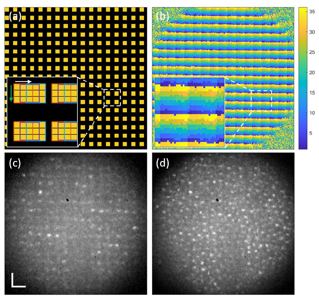
(a) A multi-spot illumination pattern with a fill factor of 0.25. The yellow squares indicate the illuminated spots. The inset shows enlarged illumination spots consisting of 3 by 3 DMD mirrors and being scanned horizontally and then vertically with a 1 DMD mirror step size. (b) A spatial filtering mask used for composite image reconstruction. Each pixel is labeled as a number between 1 and 36 (the number of subframes), here shown as colors. (c) A single subframe retinal image of N1 at 6° TR. (d) A single reconstructed retinal image from (c) and the other 35 subframes. The scale bar is 20 μm.
A composite frame was reconstructed by adding the set of spatially filtered subframe images. A spatial filtering mask was obtained by assigning a label to every image pixel such that pixels illuminated by the same DMD pattern have the same label. This assumes that the pixels under illumination have the highest intensity among all other image pixels. Subframes captured by the same illumination pattern were averaged to exclude retinal structural features, and the resultant complementary illumination pattern images were used for comparing intensities and assigning a label for each pixel. Figure 2(b) shows the spatial filtering mask for the complementary multi-spot patterns with a fill factor of 0.25 and its enlarged image in the inset. Each color represents one DMD illumination pattern. This calibration step was repeated for each subject as accurate DMD to Photron pixel registration is critical. This also avoids the magnification errors if a model eye was used for example.
Spatial filtering of the camera image worked as a set of virtual pinholes, filtering out scattered light from the non-illuminated areas and out of focus layers. Only the pixels corresponding to the central area (1 mirror element) of the illumination spots were used for reconstruction for improved confocality. Figure 2(c) and (d) show one of the 36 subframe images of N1 at 6° TR captured by the multi-spot patterns with a fill factor of 0.25 and a reconstructed image using 36 complementary subframe images and the mask presented in Fig. 2(b), respectively. Up to 50 composite images were then registered together using a cross-correlation-based method with subpixel accuracy and were averaged to increase signal-to-noise ratio. Michelson contrast, which is was then calculated using average of ten highest and lowest intensity values in a region of interest (ROI) with size of 30 by 30 pixels to evaluate image quality.
The axial resolution was measured by the intensity response with axial scanning following Romero-Borja et al. [13] using a 10 D model eye, diffuse target, and 0.5 ADD virtual pinhole. The full width at half maximum (FWHM) of the intensity-distance plot was considered as the axial resolution of the imaging system.
Figure 3 shows photoreceptor images and normalized radial power spectrum of N2 at the fovea and 6° TR acquired with the three illumination patterns. The grayscale is adjusted for each image so that the top 0.1% of pixels are saturated and pixels equal or lower than 25% of the upper limit are set to zero. Under flood illumination, Fig. 3(a), the foveal cones are visible, but the contrast is reduced due to the out of focus light. As the fill factor of the illumination patterns decreases, Fig. 3(b) and (c), photoreceptor contrast improves, revealing the hexagonal packing structure of cones in Fig. 3(c). It is verified by the increased spectral signal at 102.6 cycles/degree (denoted by the vertical line) with fill factor of 0.11 in Fig. 3(d). Estimated cone spacing was 2.92 μm which agrees with our previously reported study [14]. At 6° TR, the flood illumination image, Fig. 3(e) and the partially confocal images, Fig. 3(f) and (g), clearly show the larger and more widely spaced cones. The rod photoreceptors, indicated by the arrows in Fig. 3(f) and (g), are also visible. In Fig. 3(h), the cone spacing at 6° TR is estimated to be 9.74 μm from the peaks denoted by the vertical line, also in agreement with [14]. The peaks corresponding to cone spacing are clearly observable even under flood illumination, while peaks corresponding to rod spacing are hard to discern even under multi-spot illumination. For both cones and rods, the peaks increase with lower illumination fill factor and hence a higher degree of confocality.
Fig. 3.
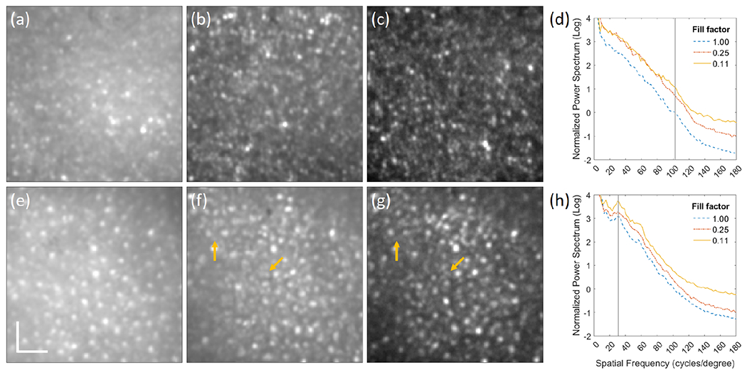
Registered average of 50 composite images of N2 with illumination fill factors of (a) 1, (b) 0.25, and (c) 0.11 at the fovea and the corresponding images at 6° TR (e)-(g). The arrows indicate rod photoreceptors. Normalized radial power spectrum of photoreceptor images of N2 at (d) fovea and (h) 6° TR. The scale bar is 20 μm.
Michelson contrast was calculated for five ROIs for each photoreceptor image of the three subjects. Figure 4(a) and (b) show box plots of the contrast at the fovea and and 6° TR, respectively. The mean and standard deviations of the contrast at the fovea is 0.10 ± 0.06, 0.18 ± 0.07, and 0.26 ± 0.08, and at 6° TR is 0.088 ± 0.03, 0.19 ± 0.05, 0.31 ± 0.09 with illumination fill factors of 1, 0.25, and 0.11, respectively. The contrast increased with lower illumination fill factor owing to improved confocality and improved 2-3 fold compared to standard flood illumination.
Fig. 4.
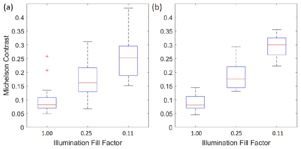
Box plots of Michelson contrast of the photoreceptor images of all three subjects at (a) fovea and (b) 6° TR.
To verify that the observed retinal features were indeed photoreceptors, a confocal photoreceptor image of N3 at 3° TR was also captured by our previously reported AO-cSLO system [15]. The same photoreceptor morphology can be observed in both systems in Fig. 5. For better comparison, 70 example cones visible by both imaging systems were marked, and normalized radial power spectrum of the images are shown in Visualization 2.
Fig. 5.
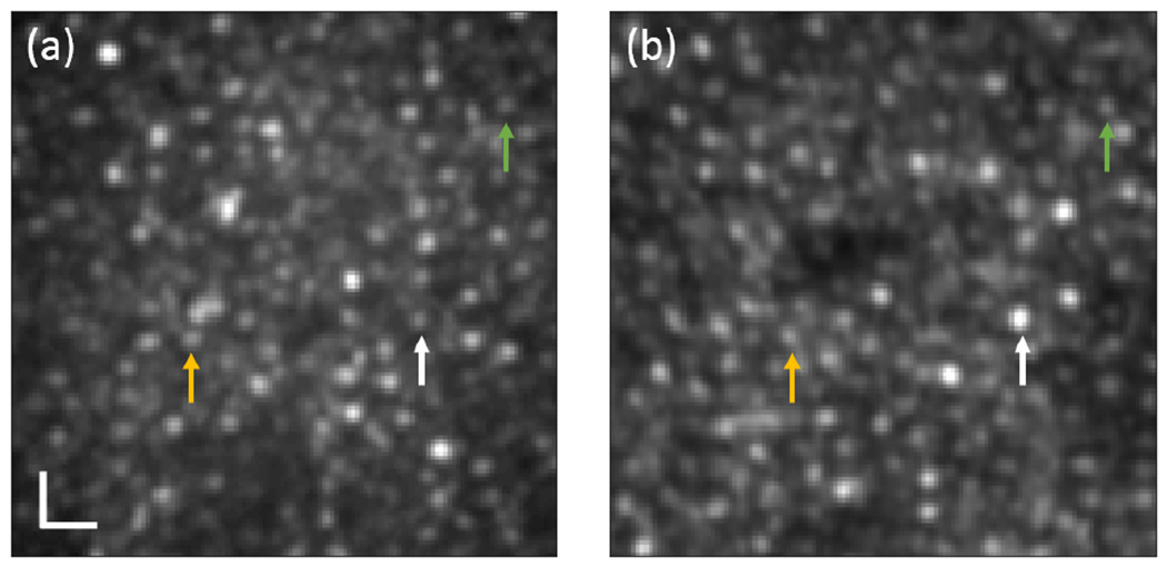
Photoreceptor images of N3 at 3° TR captured by (a) the AO-pcMSO system with an illumination fill factor of 0.11 and (b) AO-cSLO system [15]. The same colored arrows indicate the same cones. The image grayscale is adjusted for comparable contrast visualization. The scale bar is 10 μm.
Figure 6(a) shows the normalized intensity as a function of axial distance for various fill factors. The defocus terms applied to DM for axial scanning were rescaled for the axial length of the human eye. The axial resolution was ~69 μm under single spot illumination (most comparable to a conventional AO-cSLO) and multi-spot illumination with fill factors of 0.016 and 0.04. The axial resolution could not be measured with the higher fill factors (0.11 and 0.25) because the background signal stays at or gets higher than half maximum, but higher intensity around zero axial distance indicates improved sectioning ability of the AO-pcMSO system compared to flood illumination (see Visualization 3). Figure 6(b)–(d) show retinal images acquired at three different axial planes corresponding to the photoreceptor layer, retinal vessel, and nerve fiber layer at 4° NR for N3 with an illumination fill factor of 0.11. The axial focal planes for retinal vessel and nerve fiber layer were 158 μm and 218 μm anterior to the photoreceptor layer, respectively.
Fig. 6.
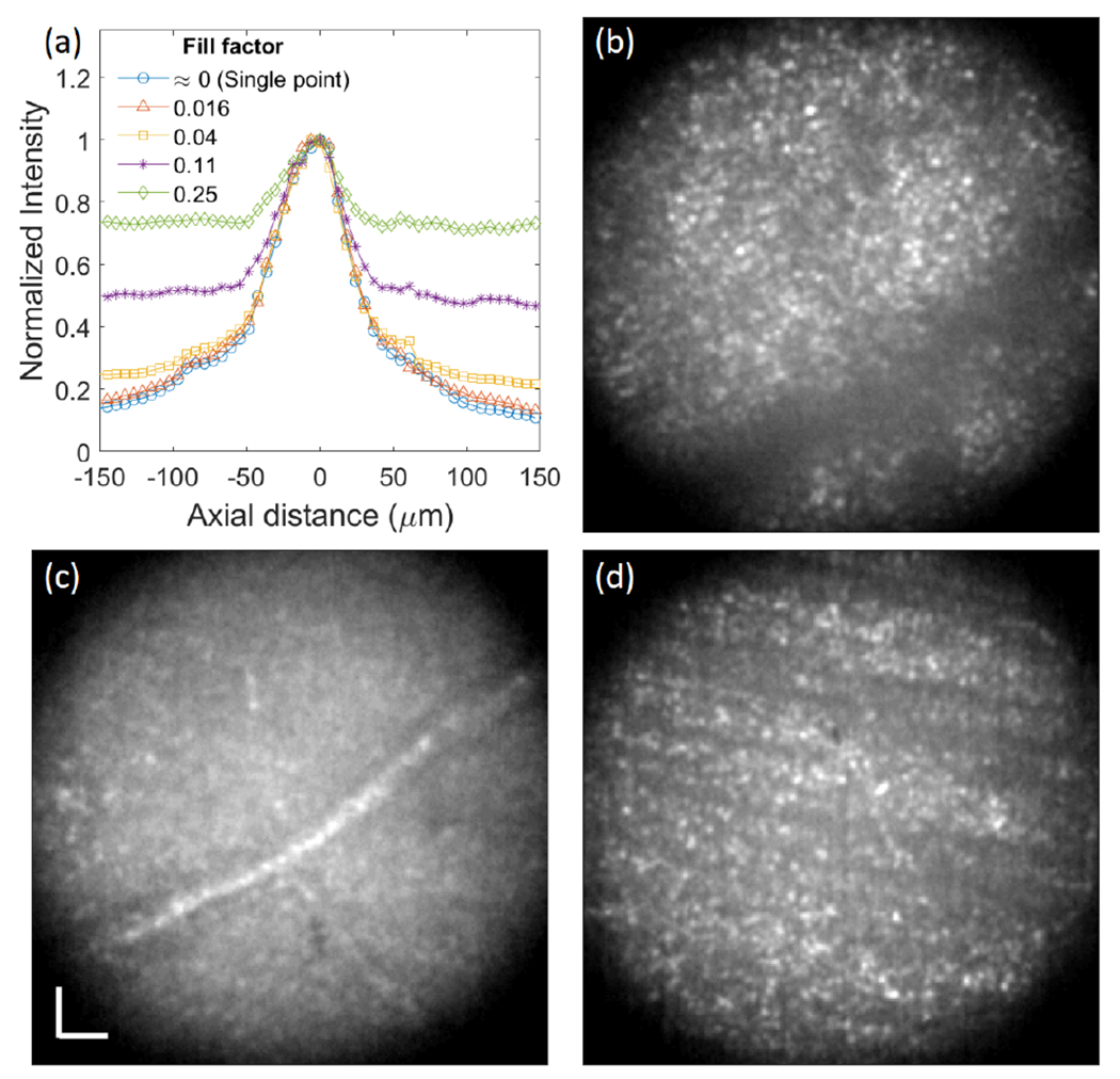
(a) Normalized axial intensity versus axial distance measurement. Retinal images of N3 at 4° NR focused on (b) photoreceptor layer, (c) retinal vessel, and (d) nerve fiber layer with an illumination fill factor of 0.11. The scale bar is 20 μm.
We have demonstrated a high-speed AO-pcMSO using a DMD and high-speed CMOS camera. The image acquisition rate and contrast trade-off can be easily controlled by applying different illumination schemes. Applying multi-spot illumination with fill factor of 0.11, we achieved 2-3 fold contrast improvement compared to flood illumination with ~250 fps frame rate. In the current system, FOV is limited to 0.7° diameter due to insufficient power of the light source, leaving a large number of Photron camera pixels and DMD mirrors unused. However, this design has the potential for easily expanding the FOV by up to ~ 3 times without costs of speed and resolution using a higher power light source.
Supplementary Material
Funding.
This research was supported by EY031098.
Footnotes
Disclosures. The authors declare no conflicts of interest.
Data availability.
Data underlying the results presented in this paper are not publicly available at this time but may be obtained from the authors upon reasonable request.
FULL REFERENCES
- 1.Liang J, Williams DR, and Miller DT, “Supernormal vision and high-resolution retinal imaging through adaptive optics,” J. Opt. Soc. Am. A 14, 2884–2892 (1997). [DOI] [PubMed] [Google Scholar]
- 2.Roorda A, Romero-Borja F, D. WJ III, Queener H, Hebert TJ, and Campbell MC, “Adaptive optics scanning laser ophthalmoscopy,” Opt. Express 10, 405–412 (2002). [DOI] [PubMed] [Google Scholar]
- 3.Martial FP and Hartell NA, “Programmable illumination and high-speed, multi-wavelength, confocal microscopy using a digital micromirror,” PLOS ONE 7, 1–9 (2012). [DOI] [PMC free article] [PubMed] [Google Scholar]
- 4.Muller MS and Elsner AE, “Confocal retinal imaging using a digital light projector with a near infrared VCSEL source,” in Emerging Digital Micromirror Device Based Systems and Applications X, vol. 10546 Douglass MR and Lee BL, eds., International Society for Optics and Photonics; (SPIE, 2018), p. 105460G. [DOI] [PMC free article] [PubMed] [Google Scholar]
- 5.Vienola KV, Damodaran M, Braaf B, Vermeer KA, and de Boer JF, “Parallel line scanning ophthalmoscope for retinal imaging,” Opt. Lett 40, 5335–5338 (2015). [DOI] [PubMed] [Google Scholar]
- 6.Damodaran M, Vienola KV, Braaf B, Vermeer KA, and de Boer JF, “Digital micromirror device based ophthalmoscope with concentric circle scanning,” Biomed. Opt. Express 8, 2766–2780 (2017). [DOI] [PMC free article] [PubMed] [Google Scholar]
- 7.Krafft L, Gofas-Salas E, Lai-Tim Y, Paques M, Mugnier L, Thouvenin O, Mecê P, and Meimon S, “Partial-field illumination ophthalmoscope: improving the contrast of a camera-based retinal imager,” Appl. Opt 60, 9951–9956 (2021). [DOI] [PubMed] [Google Scholar]
- 8.Lu J, Gu B, Wang X, and Zhang Y, “Adaptive optics parallel near-confocal scanning ophthalmoscopy,” Opt. Lett 41, 3852–3855 (2016). [DOI] [PMC free article] [PubMed] [Google Scholar]
- 9.Lu J, Gu B, Wang X, and Zhang Y, “High speed adaptive optics ophthalmoscopy with an anamorphic point spread function,” Opt. Express 26, 14356–14374 (2018). [DOI] [PMC free article] [PubMed] [Google Scholar]
- 10.Findlay JM, “Frequency analysis of human involuntary eye movement,” Kybernetik 8, 207–214 (1971). [DOI] [PubMed] [Google Scholar]
- 11.Rha J, Jonnal RS, Thorn KE, Qu J, Zhang Y, and Miller DT, “Adaptive optics flood-illumination camera for high speed retinal imaging,” Opt. Express 14, 4552–4569 (2006). [DOI] [PubMed] [Google Scholar]
- 12.Laser Institute of America, “American National Standard for safe use of lasers ANSI Z136.1-2018,” (2018).
- 13.Romero-Borja F, Venkateswaran K, Roorda A, and Hebert T, “Optical slicing of human retinal tissue in vivo with the adaptive optics scanning laser ophthalmoscope,” Appl. Opt 44, 4032–4040 (2005). [DOI] [PubMed] [Google Scholar]
- 14.Wells-Gray EM, Choi SS, Bries A, and Doble N, “Variation in rod and cone density from the fovea to the mid-periphery in healthy human retinas using adaptive optics scanning laser ophthalmoscopy,” Eye 30, 1135–1143 (2016). [DOI] [PMC free article] [PubMed] [Google Scholar]
- 15.Wells-Gray EMM, Choi SS, Zawadzki RJ, Finn SC, Greiner CA, Werner JS, and Doble NP, “Volumetric imaging of rod and cone photoreceptor structure with a combined adaptive optics-optical coherence tomography-scanning laser ophthalmoscope,” J. Biomed. Opt 23, 036003 (2018). [DOI] [PMC free article] [PubMed] [Google Scholar]
Associated Data
This section collects any data citations, data availability statements, or supplementary materials included in this article.
Supplementary Materials
Data Availability Statement
Data underlying the results presented in this paper are not publicly available at this time but may be obtained from the authors upon reasonable request.


