Abstract
A highly sensitive low-cost strain sensor was fabricated in this research study based on microdispensing direct write (MDDW) technique. MDDW is an additive manufacturing approach that involves direct deposition of functional material to the substrate. The devices were printed directly onto a polymeric substrate by optimizing the fabrication parameters. A composite of silver and carbon was used as active sensor material where both materials in the composite have opposite resistance temperature coefficients. The ratio of materials in the composite was selected so that the effect of temperature on the resistance of overall composite was canceled out. This resulted in achieving temperature compensation or inherent independence of the strain sensor resistance on temperature without requiring any additional sensors and components. The sensor was further encapsulated by electrospray deposition, which is also an additive manufacturing approach, to eliminate the effect of humidity as well. Electrical and morphological characterizations were performed to investigate the output response of the sensors and their physical and structural properties. An analog signal conditioning circuit was developed for seamless interfacing of the sensor with any electronic system. The sensor had an excellent gauge factor of 45 and a strain sensitivity of 45 Ω/μɛ that is higher than most of the conventional strain sensors. The sensor's response showed excellent temperature and humidity compensation reducing the relative effect of temperature on the resistance by ∼99.5% and humidity by ∼99.8%.
Keywords: microdispensing direct write, additive manufacturing, strain sensor, temperature compensation, humidity compensation, high gauge factor
Introduction
Strain sensors are one of the most widely used mechanical sensors that find their role in many areas such as automotive applications, robotics, structural health monitoring of aircrafts and civil structures, human motion detection, and many others.1–4 They are utilized for strain, stress, and shape monitoring applications. These applications require detection of microstrain μƐ with great precision to prevent failure under load. Most of the commercially available strain sensors are metallic foil-based structures supported on polymeric substrates. They are less sensitive and usually have gauge factors (GFs) in range of 1–6. Printed strain sensors based on different materials such as carbon,5 silver,6 carbon nanotubes,7 graphene,8 and poly(3,4-ethylenedioxythiophene) polystyrene sulfonate9 are becoming popular because of their higher sensitivity and flexibility of fabrication on number of substrates such as polyamide,10 polyisoprene,11 polymethyl methacrylate,12 polyethylene terephthalate,13 and polyurethane.14 These strain sensors are highly sensitive with GFs ranging from 0.35 to 176 and can be utilized for microstrain μɛ detection.15–19
It can be noted that the GF of such unconventional strain sensors has been considerably improved as compared with the conventional metallic gauges, but the problem with these type of sensors is that their performance is affected by environmental factors such as temperature and humidity.9 These environmental factors can lead to strain measurement error if not addressed properly. The strain sensor resistance may increase or decrease depending on the temperature coefficient of resistance (TCR). To make the sensor temperature independent, different temperature compensation techniques have been developed. These temperature compensation methods include numerical-based techniques,20 neutral axis technique,21 differential amplifier-based technique,22 Wheatstone bridge-based techniques,23 stack layer of thin film of two different materials with opposite TCR,24 and hybrid nanocomposite material with opposite TCR.25 These methods show good temperature compensation but require additional sophisticated circuitry and components to achieve compensation.20 In case of neutral axis techniques,21 the GF is compromised. And for the bridge-based differential methods for compensation,22 an additional dummy strain sensor is required that is a serious limitation in space-constrained complex mechanical systems. The effort to use stacked multilayered structure of different materials24 with opposite temperature coefficients of resistance resulted in a low GF of ∼5. Furthermore, the use of additional components can in return contribute to additional residual errors that is seldom considered while designing the compensation circuitry. To address the mentioned limitations, Ramalingame et al.25 presented a strain sensor based on hybrid nanocomposite material of graphene and multi-walled carbon nanotubes (MWCNT) that did not require any additional components for compensation but had its own limitations such as relatively lower gauges factor (∼16), patch-like structure resulting in nonuniform stress distribution, physical morphology of the sensor prone to damage by abrasion, and non-additive device fabrication method. Second, in addition to temperature, the output of the strain sensor is also affected by the relative humidity of surrounding environment.26 Most of the metallic strain sensors have negligible effect of humidity, but they have low sensitivity. The nonconventional materials-based sensors have higher strain sensitivity but also have a higher sensitivity toward humidity. The resistance of strain sensor changes substantially with change in relative humidity that is a direct error in measurement and can be even higher than the temperature-based error. To reduce the effect of humidity on sensor performance, usually a hydrophobic coating/encapsulation is done. Ahuja et al.26 reported strain sensor based on polydimethylsiloxane (PDMS) protective layer. Chen et al.27 presented strain sensor based on carbon black nanoparticles (NPs) as sensor material and PDMS super hydrophobic coating. Wang et al.28 fabricated super hydrophobic strain sensor based on MWCNTs/PDMS. None of these studies addressed temperature issue along with humidity.
So far, researchers working on the development of strain sensors have only focused on one or maximum two of the three major parameters that include an aim to achieve high strain sensitivity (GF), eliminate the effect of temperature, and eliminate the effect of humidity. This study focuses on additive manufacturing-based fabrication of strain sensors that targets improvement in all three areas. Temperature compensation was achieved using the hybrid nanocomposite material-based approach to eliminate the requirement of additional circuitry and residual errors due to those components, effect of humidity was eliminated by encapsulating the printed sensors with a hydrophobic coating deposited using spray coating, and the sensor design and materials were optimized to achieve a high GF of 45. The sensors had a stable and robust morphology and were not damaged by physical contact making them a realistic option for practical applications.
Materials and Methods
The sensors were fabricated using a composite paste based on silver nanoparticles (Ag-NPs) and Carbon paste. Ag-NP ink was supplied by PARU and carbon paste was supplied by Guangzhou Print Area Technology with a nominal viscosity of ∼20,000 cP. The viscosity of silver ink was 300 cP, whereas the weight percentage of silver in the ink was unknown. A known weight of ink was dried and the silver residue was weighted again. The approximate weight percentage of silver in the ink was found to be 50%. Carbon paste and Ag-NP's ink were then mixed together in 4.6:1 weight by weight to get the final composite paste with a viscosity of ∼17,000 cP. The mixture was thoroughly stirred to uniformly distribute the Ag-NPs in the highly viscous carbon paste. Once a uniform distribution was ensured, the nanoparticles remained suspended and did not settle down or no issue of agglomeration was observed due to very high viscosity of the paste. Weight by weight ratio of carbon and silver in the final composite was ∼7.8:1 (0.85 × 4.6: 0.5 × 1). The specific ratio of the materials for the composite was selected because the resistance temperature coefficient of silver (α ≈ +0.004/°C) is positive (resistance increases with increasing temperature), whereas the resistance temperature coefficient of carbon (α ≈ −0.0005/°C) is negative (resistance decreases with increasing temperature).29 This gives the composite a property of temperature independence due to opposite TCR if mixed together in a defined ratio. The ratio of these coefficients come out to be ∼8:1 that determined the ratio of silver and carbon in the composite. After optimizing the material composition and viscosity, the sensors were fabricated on a polyethylene terephthalate substrate using the carbon/silver paste through microdispensing direct write (MDDW) technique.
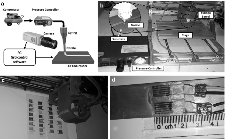
The sensor fabrication was done with the printing nozzle mounted on a Woodpecker computerized numerical control (CNC) router. The substrate was mounted on a movable XY-stage. The “grblcontrol” application was used to control and program the CNC machine. A syringe barrel was attached to the Z-axis of CNC machine in which the material paste was filled. A nozzle was attached with one end of syringe barrel, whereas the other end was connected to the pneumatic pressure tubing. An air compressor was used to generate the pneumatic pressure, which was controlled by an electronic pressure controller. This controlled air pressure was then connected to the syringe barrel for ink extrusion. Figure 1a shows the schematic of the experimental setup used in this study, whereas Figure 1b shows the actual setup image.
FIG. 1.
Direct ink write printing process showing (a) the schematic, (b) actual experimental setup, (c) array of printed strain sensor samples, and (d) sensors mounted on aluminum beam with dimensions.
Uniform pattern printing was achieved by optimizing different printing parameters, including standoff distance between the substrate and the nozzle, applied pneumatic pressure, nozzle size, feed rate of CNC stage, and the ink viscosity. A summary of the optimized printing parameter values for the process are presented in Table 1.
Table 1.
Optimized Printing Parameters
| Parameters | Value |
|---|---|
| Standoff distance (mm) | 0.1 |
| Pressure (psi) | 5 |
| Feed rate (mm/min) | 200 |
| Nozzle diameter (μm Internal) | 750 |
| Ink viscosity (cP) | ∼17,000 |
The fabricated sensors were cured at 140°C for 30 min in an air convection oven to evaporate the solvent and form solid conductive paths for the flow of current. One of the fabricated device samples was then encapsulated with a hydrophobic coating of zinc oxide (ZnO) + poly(methyl methacrylate) (PMMA) composite using pneumatic air spray technique that is also an additive manufacturing approach. PMMA (mol wt of repeat unit 100.12) was dissolved in toluene solvent with a wt%/vol of 5% and ZnO nanoparticles were dispersed in the solution to prepare the ink for spray coating. The device design was based on meander-type patterns that is the most common design for strain sensors owing to its better sensitivity because of higher intrinsic resistance as compared with a single line. Length of the fabricated sensors was ∼1.2 cm, whereas the width and gap between each electrode line was kept at ∼1 mm. These dimensions were selected to have a fair comparison of fabricated sensors with the common metallic strain sensors available in the market. Changing the number of patterns, length and width of pattern, and thickness of pattern will change the intrinsic resistance of the sensor and in return the sensitivity. Any dimensions can be used for the sensor until they are within the tensile strength of the material and devices are not damaged upon application of strain. Multiple identical devices were fabricated as presented in Figure 1c to ensure repeatability of results. The fabricated devices mounted on an aluminum bar are presented in Figure 1d. The images show high-resolution regular patterns without any visible defects and nonuniformities.
Sensor Characterization
The sensors were characterized in detail for their physical and electrical behavior and response. Carefully designed experimental setups were used to ensure reliable and reproducible results and enable exploring the different device performance parameters. Scanning electron microscopy (SEM) using Carl Zeiss Supra 55VP and atomic force microscopy (AFM) were performed to investigate the physical morphology and structure of the sensing devices. Detailed electrical characterizations were performed to investigate the performance of the sensors.
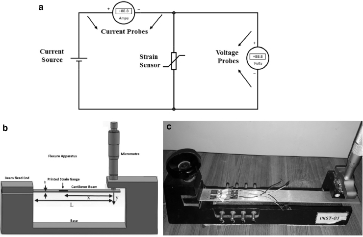
Current-voltage (I-V) characterization of the sensors was performed to confirm Ohmic behavior of the devices. Figure 2a shows the schematic diagram for the I-V characterization setup. Four probe method was used to determine the I-V characteristics. A current source was connected across the sensor and the resulting voltage drop due to the flowing current was measured by the voltage probe. Controlled current source was used to avoid overheating of the sensor and resulting damage to the sensing material.
FIG. 2.
Characterization setups showing (a) the four probe setup schematic for I-V characterization and (b, c) the flexure apparatus schematic and setup to measure strain sensitivity.
Strain sensitivity of the sensor was investigated by mounting it on an aluminum beam with the dimensions of 318 × 25 × 4 mm. To get accurate results and make a good contact between the sensor and the beam, the surface of the beam was made smooth by abrasion, cleaned with acetone, and the strain sensor was pasted on the cleaned surface using epoxy. Flexure apparatus was used to determine the strain sensitivity in conjunction of a signal conditioning circuit. Figure 2b and c shows the schematic and actual diagram of the flexure apparatus, respectively. The beam was deflected using a standard micrometer attached at one end of the flexure. The sensor resistance was measured using a digital inductance, capacitance and resistance meter (Applent AT-826). The value of applied strain was determined using Equation (1) and was also compared with standard strain gauges.
| (1) |
Here strain acting on strain sensor at distance X from deflection point; h is beam thickness; L is the beam length; and y is the deflection at free end of the cantilever beam. The ratio of change in resistance to the initial resistance (ΔR/R) of the developed sensor was plotted against the standard applied strain values for calibration of the fabricated strain sensors. Results of calculated strain, measured strain using standard gauge mounted on the Al beam, and measured strain using the fabricated sensor in this study are compared in later sections.
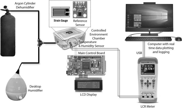
The aim of this research study was to develop a strain sensor that can be used in harsh and unstable environments where parameters such as temperature and humidity may vary substantially. The effects of humidity and temperature on the output of sensors were recorded using an automatic controlled environmental chamber as shown in Figure 3. Relative humidity of the chamber was changed from 0% RH to 80% RH, whereas keeping the temperature constant to investigate the effect of humidity first. After that, the humidity was kept constant and the temperature was changed to investigate its effect. The resistance of the sensor was measured using a digital LCR meter. The resistance along with the chamber humidity and temperature were automatically logged and plotted on a computer.
FIG. 3.
Computerized characterization setup to investigate temperature and humidity effects on sensor resistance.
Wheatstone bridge was used to convert the change in resistance into change in voltage. The bridge was balanced at zero strain applied using Equation (2) by adjusting the variable resistances.
| (2) |
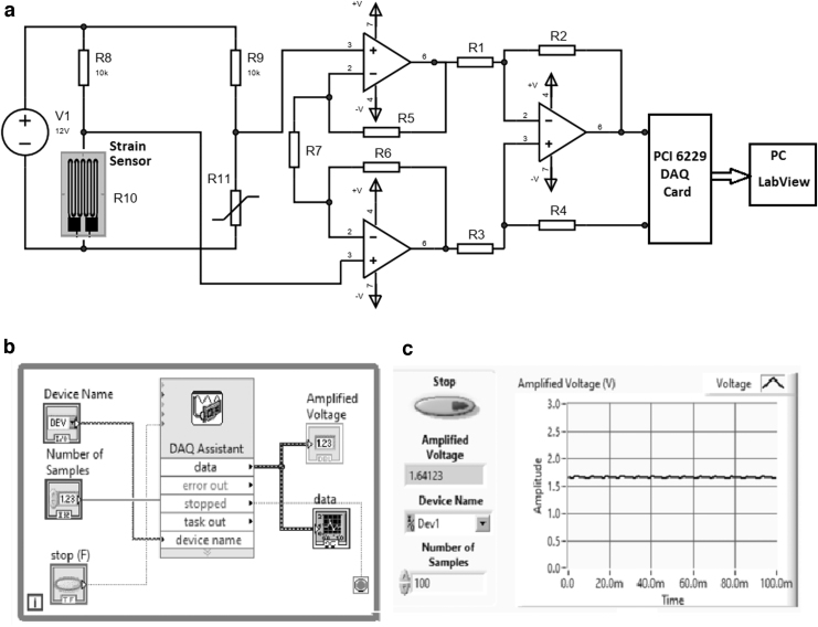
To improve sensitivity and signal to noise ratio and eliminate the effect of common mode noise, the differential output of the bridge was amplified using an instrumentation amplifier (INA-229 HT)-based signal conditioning circuit as presented in Figure 4a. Gain of the amplifier can be found using Equation (3).
FIG. 4.
Detailed signal conditioning system showing the (a) circuit design, (b) LabVIEW program interface block diagram, and (c) the plot of voltage representing strain with time.
| (3) |
Output voltage of the instrumentation amplifier was further connected to National Instruments (NI) data acquisition card (DAQ) PCI 6229 to automatically log and plot the values of strain versus voltage. Figure 4b shows the block diagram of LabVIEW VI and Figure 4c shows the graph of amplified signal on the LabVIEW. The developed user interface was simple to use and provided accurate results with high resolution.
The developed NI DAQ system and software interface confirms that the sensors can be used in automation industries and can be seamlessly integrated with the existing systems and setups.
Results and Discussion
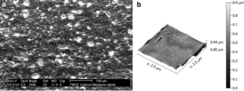
Sensor microstructure was visualized using SEM and AFM. SEM was performed to visualize particle matrix of the sensor and the results presented in Figure 5a show that the structure of carbon/silver composite is closely bound ensuring good electrical conductivity. Moreover, there are no visible cracks or defects in the structure at the microlevel that verifies the fabrication process to be efficient and ensures long-term structural integrity of the devices.
FIG. 5.
Microstructure of the device showing (a) Surface SEM results and (b) AFM 3D profile. 3D, three-dimensional; AFM, atomic force microscopy; SEM, scanning electron microscopy.
AFM was performed to study the surface roughness of the printed strain sensor. The results presented in Figure 5b show that the average surface roughness is ∼219.15 nm and root mean square surface roughness is 51.16 nm. Good surface roughness ensures long-term stability of the flexible devices.
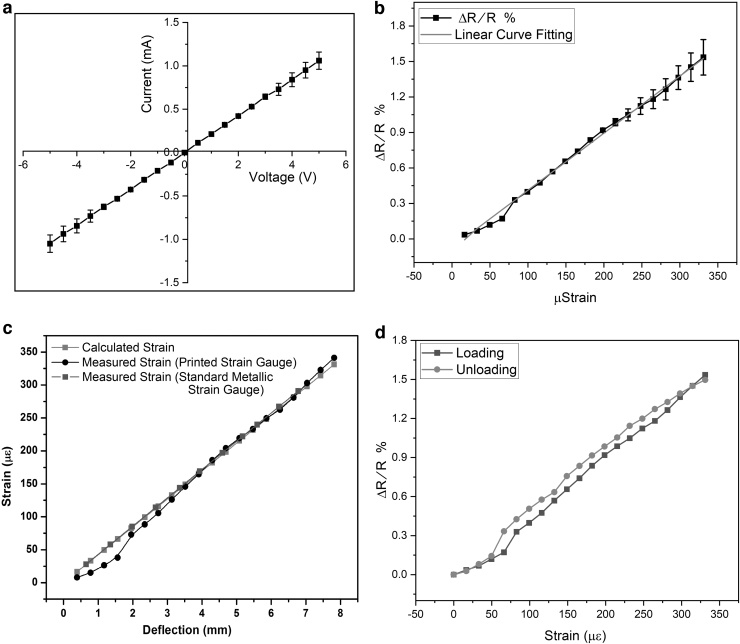
Figure 6a shows the I-V characteristic curve for the sensing devices with three trials of readings. This characterization was performed to validate the Ohmic behavior of sensors as it is crucial for correct strain calculations using the standard formulae. The I-V response curve confirmed Ohmic for both positive and negative voltages showing linear relationship between current and voltage. The sensor showed a constant intrinsic resistance of ∼7 kΩ at zero strain. This relatively high resistance of the sensor as compared with metallic strain gauges is due to the presence of carbon in the composite. Higher intrinsic resistance is better for higher sensitivity as it allows higher magnitude of absolute change in the output.
FIG. 6.
Electrical characterizations of the device showing (a) the I-V characterization curve displaying Ohmic behavior, (b) strain sensitivity curve showing linear relationship, (c) comparison of strain values determined using different methods, and (d) strain hysteresis curve showing minimal hysteresis for loading and unloading.
Figure 6b shows the strain sensitivity/GF of the fabricated sensors for three samples. The graph shows that resistance increases almost linearly with increasing strain, thus assuring direct relationship between relative changes in resistance versus strain with average correlation factor (R2) of 99.6%. The error bars show the variation of relative change in resistance for different samples. The change in resistance with strain was relatively smaller at very low values of applied microstrain. This shows that the sensitivity of the devices toward very low strain is lower when compared with higher strain values; resulting in a slightly nonlinear behavior in the beginning of the curve, whereas it becomes almost linear when the applied strain increases >50 μƐ. The strain sensitivity was determined by its GF that was calculated using Equation (4)30:

GF determines how much relative change in resistance occurs for a given value of strain. The GF determined experimentally for this sensor was 40 ± 5 that is many times higher than most of metallic commercial strain sensors.
Based on the results of Figure 6b, the sensors were calibrated to calculate the actual value of strain using the fabricated sensors. The results of strain calculated using standard commercial strain gauge mounted on the Al beam, value of strain calculated using the fabricated printed sensor, and the theoretically determined strain determined using Equation (1) are presented in Figure 6c. The results show that the theoretical curve of strain (red) and standard metallic strain gauge curve (blue) have a negligible difference of 1.3%, whereas the strain curve of the sensor fabricated in this study (black) has a difference of just 3.7% when compared with the standard. This shows excellent accuracy of the fabricated sensor for strain measurement.
Relative change in resistance of the fabricated sensors in loading and unloading directions was investigated and the results presented in Figure 6d show a slight hysteresis of 0.038%. This hysteresis effect may be due to interfacial bonding between carbon and silver in the composite material. Important point to note here is that the hysteresis was not a permanent hysteresis (complete recovery at zero strain) that does not affect the long-term stability of the devices and the accuracy of results.
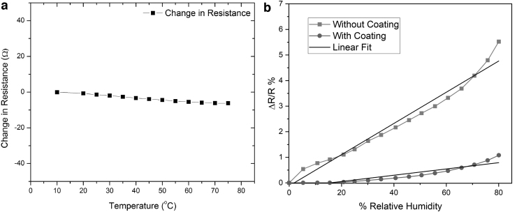
The results of effect of change in temperature on the resistance of the sensor presented in Figure 7a show that the resistance decreases linearly with increasing temperature, but the magnitude of change is negligible. From the graph, the temperature sensitivity (ΔR/ΔT) was found out to be −0.1 Ω/°C, where ΔR is change in resistance and ΔT is change in temperature. This is a negligible (0.2%) value when compared with the strain sensitivity of the sensor that is 45 Ω/μƐ. The TCR for the composite-based sensor was calculated using Equation (5).
FIG. 7.
Effect of environmental parameters on sensor's resistance showing (a) effect of change in temperature and (b) effect of change in relative humidity.
| (5) |
Here Ro is nominal resistance of the strain sensor, whereas ΔR/ΔT is the temperature sensitivity. The TCR of strain sensor was calculated to be α ≈ −0.000013/°C. Although, it shows somehow dominant behavior of carbon in the composite; it can be further improved by slightly reducing the amount of carbon to ∼75%. Nevertheless, the results are not at all bad if we compare them with a pure carbon-based strain sensor5 having a temperature sensitivity of −12.56 Ω/°C and a TCR of 0.00416/°C that has been successfully decreased by ∼99.7%.
Results of the effect of change in surrounding humidity on the resistance of sensors presented in Figure 7b show that resistance of both coated and noncoated sensors increases with increase in humidity. Sensitivity of the noncoated sensor toward humidity change was found out to be 3.55 Ω/%RH, whereas the sensitivity of coated sample was calculated to be 0.29 Ω/%RH. This means that the sensor performance improved by 99% in humid environment with protective coating.
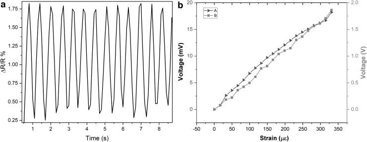
To evaluate the characteristics of the sensor in structural vibrations, dynamic response of the devices was investigated and the results are presented in Figure 8a. The Al beam was subjected to cyclic deflections of 2.4 mm at the free end with a frequency of 1 Hz and the resistive response of the sensor was recorded. The results show that the response of sensors is highly reproducible and repeatable for multiple cycles of loading and unloading. The high sensitivity of sensors enables them to successfully detect very small rapid strain changes (vibrations).
FIG. 8.
(a) Dynamic response of the sensor for multiple loading and unloading cycles and (b) voltage output of the conditioning circuit versus microstrain.
As a final step, the signal conditioning and interface circuit presented in the earlier section was used to provide a voltage gain of 100 to the differential output of the Wheatstone bridge. Figure 8b shows the output for various levels of applied strain with the red curve (A) showing the differential voltage output of Wheatstone bridge and the black curve (B) showing the amplified voltage output. The curve is free of any noise and is similar to the actual strain versus resistance curve of Figure 6. A little bit of change in the linearity of the curve is because the Wheatstone bridge is a nonlinear device. We are still getting an advantage of the nonlinearity of the bridge output here as the sensitivity of the bridge decreases nonlinearly, whereas the sensitivity of our sensor was increasing. These individual effects are opposing in nature and result in a voltage versus strain curve with a better linearity.
A detailed comparison of the performance parameters of our device with the similar sensors reported in the literature has been presented in Table 2. The comparison clearly shows that there are many sensors fabricated using nonconventional materials that have successfully achieved high GFs and have been fabricated using additive manufacturing approaches. The major disadvantage of these sensors, however, is their inability to compensate for temperature and humidity effects. Then there are studies reporting temperature compensation using various techniques, but they have compromised the GF in the process and are fabricated using nonadditive manufacturing approaches. The sensor fabricated in this study successfully addresses the aforementioned limitations by reducing the temperature and humidity effect on the sensor output by >99.5% without requiring any additional components and retaining a very good GF. Plus, the sensors have been fabricated using all printed methods based on additive manufacturing approaches.
Table 2.
Performance Comparison with Sensors Reported in the Literature
| Refs. | Fabrication method | Sensor dimensions | Sensor material | Temperature compensation | Humidity compensation | GF |
|---|---|---|---|---|---|---|
| 18 | Screen printing | — | Carbon ink | No | No | 10–20 |
| 17 | Screen printing | 8 × 8 mm | Silver-Carbon | No | No | 3–57 |
| 31 | Roll-to-roll gravure printing | 10 × 17 × 0.5 mm gap | Silver | No | No | 1–2.25 |
| 5 | DIW | 5 × 4 mm | Carbon paste | No | No | 59 |
| 32 | FDM | 40 × 2 mm | PLA | No | No | 0.5–6.6 |
| 33 | FDM | 5 × 5 mm | PU/MWCNT | No | No | 8.6–176 |
| 34 | FDM | 5 mm Diameter | ABS resin | No | No | 1–10 |
| 35 | DIW | 5 mm length | PVP/MWCNT | No | No | 13 |
| 36 | DIW | 8 × 8 × 10 mm | Graphene/PDMS | No | No | 448 |
| 20 | Screen printing | — | CNT | Numerical Model | No | — |
| 21 | Screen printing | 20 mm | Graphite ink | Neutral Axis Method (0.04%/°C) | No | 19.1 |
| 23 | Screen printing | 16 × 9 × 1.4 mm gap | Graphite | Wheatstone Bridge (99.8%) | No | 2.994 |
| 24 | Thin film | 4 × 4 cm | SWCNTs/Graphene | Stack layer of two materials (99.8%) | No | 5.44 |
| 25 | Thin film | 20 × 5 mm | MWCNCTs/Graphene | Hybrid nanocomposite (99.5%) | No | 16.2 |
| This study | Direct ink write | 12 × 10 × × 1 mm gap | Carbon/Silver | Composite Material Method (99.8%) | Hydrophobic encapsulation (99.5%) | 45 |
CNT, carbon nanotubes; DIW, direct ink write; FDM, fused deposition modeling; GF, gauge factor; MWCNCT, multi-walled carbon nanotubes; PU/MWCNT, polyurethane/multi-walled carbon nanotubes; PDMS, polydimethylsiloxane; PLA, polylactic acid; SWCNT, single-walled carbon nanotubes.
Conclusion
This research study presents successful fabrication and in-depth characterization of a highly sensitive temperature-independent resistive strain gauge. The sensors were further coated with a hydrophobic coating to protect against the effects of humidity. All fabrication steps of the devices were based on additive manufacturing printing techniques. MDDW technique was used to print the device patterns, whereas pneumatic air spray was used to encapsulate the device. A novel material composite of Ag-NP and carbon was used to achieve temperature independence owing to the opposing resistive response of both materials toward change in temperature. Process parameters were optimized for the fabrication of sensors to allow smooth printing and structurally sound devices. Strain sensitivity of the sensor, also known as GF, was experimentally determined to be 45 that is much better than the conventional metallic strain sensors. In addition, the achieved relative temperature dependence of the sensor as compared with the actual strain was just 0.2% indicating excellent temperature compensation/independence. The dependence of sensors' resistance on relative humidity was also successfully reduced by ∼99%. Furthermore, a sophisticated signal conditioning and interface circuit was designed for the sensor to achieve better sensitivity and reject common mode noise. A standard DAQ-based system was also implemented to allow seamless integration of the devices with existing analog and computer-based commercial systems.
Acknowledgments
The authors are grateful to Higher Education Commission of Pakistan (HEC) for funding this research under NRPU Project No. 5548 and indebted to GIK institute for providing necessary laboratory facilities for this research.
Author Disclosure Statement
No competing financial interests exist.
Funding Information
Higher Education Commission of Pakistan (HEC) under National Research Programme for Universities (NRPU) Project No. 5448.
References
- 1. Kiełczewski JM. Strain gauges in structural health monitoring of bridge objects (Doctoral dissertation, Instytut Dróg i Mostów), 2019. [Google Scholar]
- 2. Khan H, Razmjou A, Warkiani ME, et al. Sensitive and flexible polymeric strain sensor for accurate human motion monitoring. Sensors (Switzerland) 2018;18:1–10. [DOI] [PMC free article] [PubMed] [Google Scholar]
- 3. Sajid M, Dang HW, Na KH, et al. Highly stable flex sensors fabricated through mass production roll-to-roll micro-gravure printing system. Sens Actuators A Phys 2015;236:73–81. [Google Scholar]
- 4. Yang YJ, Aziz S, Mehdi SM, et al. Highly sensitive flexible human motion sensor based on ZnSnO3/PVDF composite. J Electron Mater 2017;46:4172–4179. [Google Scholar]
- 5. Shakeel M, Khan WA, Rahman K. Fabrication of cost effective and high sensitivity resistive strain gauge using DIW technique. Sens Actuators A Phys 2017;258:123–130. [Google Scholar]
- 6. Andò B, Baglio S, La Malfa S, et al. All inkjet printed system for strain measurement. Proceedings of IEEE Sensors, 2011; IEEE, pp. 215–217. [Google Scholar]
- 7. Wang X, Sparkman J, Gou J. Strain sensing of printed carbon nanotube sensors on polyurethane substrate with spray deposition modeling. Compos Commun 2017;3:1–6. [Google Scholar]
- 8. Tian H, Shu Y, Cui Y-L, et al. Scalable fabrication of high-performance and flexible graphene strain sensors. Nanoscale 2014;6:699–705. [DOI] [PubMed] [Google Scholar]
- 9. Thompson B, Yoon HS. Aerosol-printed strain sensor using PEDOT:PSS. IEEE Sens J 2013;13:4256–4263. [Google Scholar]
- 10. Wang N, Xu Z, Zhan P, et al. A tunable strain sensor based on a carbon nanotubes/electrospun polyamide 6 conductive nanofibrous network embedded into poly (vinyl alcohol) with self-diagnosis capabilities. J Mater Chem C 2017;5:4408–4418. [Google Scholar]
- 11. Knite M, Tupureina V, Fuith A, et al. Polyisoprene—multi-wall carbon nanotube composites for sensing strain. Mater Sci Eng C 2007;27:1125–1128. [Google Scholar]
- 12. Li S, Park JG, Wang S, et al. Working mechanisms of strain sensors utilizing aligned carbon nanotube network and aerosol jet printed electrodes. Carbon N Y 2014;73:303–309. [Google Scholar]
- 13. Lee T, Choi YW, Lee G, et al. Transparent ITO mechanical crack-based pressure and strain sensor. J Mater Chem C 2016;4:9947–9953. [Google Scholar]
- 14. Li M, Li H, Zhong W, et al. Stretchable conductive polypyrrole/polyurethane (PPy/PU) strain sensor with netlike microcracks for human breath detection. ACS Appl Mater Interfaces 2014;6:1313–1319. [DOI] [PubMed] [Google Scholar]
- 15. Liu H, Zhang H, Han W, et al. 3D printed flexible strain sensors: from printing to devices and signals. Adv Mater 2021;2004782:1–19. [DOI] [PubMed] [Google Scholar]
- 16. Anderson N, Szorc N, Gunasekaran V, et al. Highly sensitive screen printed strain sensors on flexible substrates via ink composition optimization. Sens Actuators A Phys 2019;290:1–7. [Google Scholar]
- 17. Bose AK, Maddipatla D, Zhang X, et al. Screen printed silver/carbon composite strain gauge on a TPU platform for wearable applications. 2020. IEEE International Conference on Flexible and Printable Sensors and Systems (FLEPS). Manchester, United Kingdom: IEEE. [Google Scholar]
- 18. Bose AK, Zhang X, Maddipatla D, et al. Highly sensitive screen printed strain gauge for micro-strain detection. 2019. IEEE International Conference on Flexible and Printable Sensors and Systems (FLEPS). IEEE, 2019; pp.1–3. [Google Scholar]
- 19. Park J, Shin K, Lee C. Mechanical aspects of the chemical mechanical polishing process: A review. Int J Precis Eng Manuf 2016;17:537–550. [Google Scholar]
- 20. Sundararaman V, Rathod VT, Mahapatra DR. Temperature compensation in CNT-composite distributed strain sensors. Smart Sens Phenomena Technol Netw Syst Integr 2015;9436:94360M. [Google Scholar]
- 21. Bessonov A, Kirikova M, Haque S, et al. Highly reproducible printable graphite strain gauges for flexible devices. Sens Actuators A Phys 2014;206:75–80. [Google Scholar]
- 22. De Venuto D, Carrara S, Cavallini A, et al. PH sensing with temperature compensation in a molecular biosensor for drugs detection. Proceedings of the 12th International Symposium on Quality Electronic Design ISQED 2011, IEEE, 2011; pp. 326–331. [Google Scholar]
- 23. Zymelka D, Togashi K, Ohigashi R, et al. Printed strain sensor with temperature compensation and its evaluation with an example of applications in structural health monitoring. Japanese J Appl Phys, 56(5S2), 05EC02. [Google Scholar]
- 24. Luo S, Liu T. SWCNT/graphite nanoplatelet hybrid thin films for self-temperature-compensated, highly sensitive, and extensible piezoresistive sensors. Adv Mater 2013;25:5650–5657. [DOI] [PubMed] [Google Scholar]
- 25. Ramalingame R, Bautista-quijano JR, Alves DDF. Temperature self-compensated strain sensors based on MWCNT-Graphene Hybrid Nanocomposite 2019;3:96. [Google Scholar]
- 26. Ahuja P, Akiyama S, Ujjain SK, et al. Water-resilient carbon nanotube based strain sensor for monitoring structural integrity. J Mater Chem A 2019;7:19996–20005. [Google Scholar]
- 27. Chen Y, Wang L, Wu Z, et al. Super-hydrophobic, durable and cost-effective carbon black/rubber composites for high performance strain sensors. Compos Part B Eng 2019;176:107358. [Google Scholar]
- 28. Wang P, Wei W, Li Z, et al. A superhydrophobic fluorinated PDMS composite as a wearable strain sensor with excellent mechanical robustness and liquid impalement resistance. J Mater Chem A 2020;8:3509–3516. [Google Scholar]
- 29. Giancoli DC. Physics: Principles with Applications, 2010. DOI: 10.1088/1751-8113/44/8/085201. [DOI]
- 30. Murray WM. Fundamental Concepts for Strain Gages. WM Murray, 1971. [Google Scholar]
- 31. Park J, Nam D, Park S, et al. Fabrication of flexible strain sensors via roll-to-roll gravure printing of silver ink. Smart Mater Struct 2018;27:85014. [Google Scholar]
- 32. Yao X, Luan C, Zhang D, et al. Evaluation of carbon fiber-embedded 3D printed structures for strengthening and structural-health monitoring. Mater Des 2017;114:424–432. [Google Scholar]
- 33. Woosley S, Abuali Galehdari N, Kelkar A, et al. Fused deposition modeling 3D printing of boron nitride composites for neutron radiation shielding. J Mater Res 2018;33:3657–3664. [Google Scholar]
- 34. Davoodi E, Montazerian H, Haghniaz R, et al. 3D-printed ultra-robust surface-doped porous silicone sensors for wearable biomonitoring. ACS Nano 2020;14:1520–1532. [DOI] [PubMed] [Google Scholar]
- 35. Wajahat M, Lee S, Kim JH, et al. Flexible strain sensors fabricated by meniscus-guided printing of carbon nanotube-polymer composites. ACS Appl Mater Interfaces 2018;10:19999–20005. [DOI] [PubMed] [Google Scholar]
- 36. Huang K, Dong S, Yang J, et al. Three-dimensional printing of a tunable graphene-based elastomer for strain sensors with ultrahigh sensitivity. Carbon N Y 2019;143:63–72. [Google Scholar]


