Abstract
Laser beam powder bed fusion (PBF-LB) is a leading technique among metal additive manufacturing (AM), and it has a wide range of applications in aerospace and medical devices. Most of the existing PBF-LB process modeling is mainly based on the fabrication of a single part on a large build plate, which is not reflective of the practical multipart PBF-LB manufacturing. The effects of batch size on the thermal and mechanical behavior of additively manufactured parts have not been investigated. In this work, the multipart PBF-LB thermomechanical modeling framework was proposed for the first time. The effects of sample numbers (1, 2, and 4) on temperature and residual stress (RS) of part-scale components were computationally investigated. It is found that RS within the parts decreased with increasing number of components per build. Parts located at the central areas of the build plate had larger RS than at the border. These findings can be beneficial for informing AM designers and operators of the optimum printing setup to minimize RS of metal parts in PBF-LB.
Keywords: powder bed fusion, additive manufacturing, process modeling, interlayer dwell time, residual stress
Introduction
Laser beam powder bed fusion (PBF-LB) additive manufacturing (AM) is a promising technology that can be applied in the production of a variety of products, for example, medical, aerospace, and automotive devices.1 The influence of PBF-LB manufacturing process parameters, part geometry, and scanning strategy on temperature evolution have been widely investigated by process modeling or experimental builds.2–4 However, most investigations to date have been based on a single part on a large build plate, which is not reflective of the industrial scale batch manufacturing of the PBF-LB manufacturing process, where typically large batch sizes of samples are arranged for simultaneous manufacturing in a single build.5,6
It is noted, however, that in some instances it is routine for a single large component or small numbers of custom parts to be printed within the same build plate.7,8 However, the effect of multipart build on residual stress (RS) and the influence of batch size on the in-service properties of additively manufactured components are still poorly understood.
The multipart PBF-LB build offers advantages of faster build time and an increased overall production rate.9 Yılmaz and Kayacan9 investigated the influences of the number of cubic-shaped samples (e.g., 10 × 10 × 10 mm3) on the temperature and RS by using the commercial “Netfabb” software and the results demonstrated that temperature increased while stress reduced with the increase in the number of samples per build. Mahmoudi10 indicated that the number of samples had an insignificant influence on the mechanical properties of tensile and compressive strengths of PBF-LB-manufactured 17–4 PH stainless steel parts.
PBF-LB operators have reported the inconsistent properties between identical specimens produced in a single build (i.e., batch manufacturing) despite uniform material, consistent manufacturing process parameters, and an equal number of laser beams in use.11,12 A change of the number of parts per build or the order in which the parts are printed (in each layer) may produce significantly different thermal histories and thus RS and mechanical properties, between identical specimens in the same build.13
The primary reason for variation in properties for the multipart fabrication is the temperature history during the physical PBF-LB manufacturing. For multipart manufacturing, there are two significant parameters that distinguish it from single-part builds: total energy input and interlayer dwell time (ILDT). ILDT is defined as the time from when the laser beam first starts in layer n, to when the laser beam first starts in layer n + 1, which includes the time for all laser sintering, laser repositioning, roller movement, powder spreading, and compaction of a layer.11
For a PBF-LB build with a larger number of parts, there will be more energy input into the powder bed compared with a build with a single part produced. The change of the number of parts per build would also result in different ILDTs, which indicates different layer cooling step times for different batch sizes of parts manufacturing, for example, 20 s for the single-part build and 55 s for the multipart manufacturing,11 permitting a greater temperature fluctuation in recently printed layers as new layers are added. The larger ILDT indicates a longer overall duration of printing and cooling during multipart PBF-LB manufacturing.
The effect of ILDT on additively manufactured parts has been widely investigated in directed energy deposition14–17 or wire arc AM.18,19 However, there are currently limited publications investigating the effects of ILDT on thermal and mechanical behaviors in PBF-LB manufacturing. Mohr et al.11 investigated the influences of ILDT on subgrain size, melt pool geometry, and hardness of 316L stainless steel by varying the ILDTs of a prism model, and the results demonstrated that an increase of ILDT via reducing scanning speed caused a decrease of the melt pool depth in PBF-LB. Williams et al.8 investigated the influences of ILDT on microstructure and porosity and the results revealed that a reduction of ILDT caused a higher (i.e., up to 200°C) surface temperature at the end of PBF-LB manufacturing and before cooling.
A previous study by Yakout et al.20 reported that the location of the part on the build plate affected the microstructure and RS of part in PBF-LB manufacturing. However, Robinson et al.21 stated that the location of the part on the build plate had no significant effects on the resulting RS of parts in PBF-LB. Also, different locations of the build plate will have different in-plane depths of powder surrounding the part and different distances from other parts and distances to the build chamber wall. It has been shown that the cooling of parts at the center of the build plate is dependent on the heat from the surrounding parts.20
In addition, for parts to be manufactured in the same build plate, the first part to be printed per layer has a longer time to cool before spreading and deposition of the new material. In contrast, the last part to be printed in each layer is immediately covered with new powder. For the multipart build, part spacing (i.e., the distance between adjacent parts) can also affect the cooling and resultant mechanical properties of PBF-LB-manufactured parts.22 Parts built with tighter spacing within the build volume have a more concentrated thermal mass, which results in potentially slower cooling.22 However, the multipart build effects on temperature and RS and variance between parts within a multipart build are yet to be widely investigated in PBF-LB.8
To date, a significant progress has been made on the process modeling of PBF-LB. However, most metal AM process simulation models found in the literature are focused on the PBF-LB manufacturing of a single part,23,24 or a small portion of a single part,23,25–27 which is contradictory with the multipart build in the real physical PBF manufacturing. Although most of the real printing consists of a batch of samples, there is limited process finite element modeling (FEM) of multipart build, and thus, multibuild effects on the thermal and mechanical behavior of parts have been largely ignored.6 Prabhakar et al.28 simulated RS formation of five cubic-shaped Inconel 718 samples during the PBF-LB process, but did not investigate the influence of sample number on RS of parts. In addition, for the convenience of computation, all the parts in the same layer were simplified to melting and cooling simultaneously in Prabhakar's research, which is inconsistent with practical manufacturing. To accurately simulate the practical manufacturing process of multipart build in PBF-LB, the printing order of components and the ILDT of each layer should be considered. The ability to accurately simulate the physical PBF-LB manufacturing process of multipart build and predict the temperature evolution and RS of parts would further advance the development of PBF-LB process modeling.
The objective of this work is to investigate the multipart build effects on temperature and RS in PBF-LB manufacturing by computational thermomechanical modeling. The results of this work could be beneficial for informing PBF-LB machine operators of the optimum build plate configuration for minimizing RS of components.
Methods
Setup of the finite element process modeling
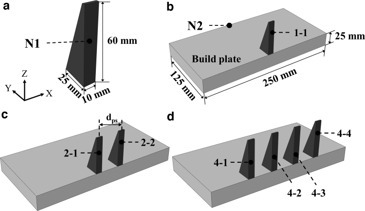
A 50-mm-long, 10-mm-wide, and 60-mm-high prism-shaped model of Ti-6Al-4V material is simulated above a build plate with a dimension of 250 mm × 250 mm × 25 mm,9,29 as shown in Figure 1. The cross-sectional area of the prism decreases along the build direction, which causes the total heat input and ILDT per layer to decrease as build height increases. To obtain the temperature and stress information for the multipart build, the sequentially coupled thermomechanical modeling is performed by the FEM software ABAQUS package (Dassault Systems, USA, 2019).25
FIG. 1.
Illustration of the computational model. (a) Geometry of prism,29 (b) single-prism model, (c) two-prism model, and (d) four-prism model.
For the sequentially coupled modeling, the thermal history is independent of the mechanical response, and the influence of structure on temperature is ignored.25 The thermal process modeling is conducted first to determine the temperature distribution, and then, the calculated temperature field is imported into the mechanical analysis to determine RS. For the mechanical analysis, the bottom of the build plate is fully constrained during the whole manufacturing process except for the build plate constraint releasing steps.
At these final steps, all the nodes at the bottom surface of the build plate, except for the four extremity nodes, are unconstrained to allow deformation of the part, simulating part removal from the build plate.30,31 Details of the model parameters can be seen in Table 1. In this work, the layer-by-layer process simulation method32 is utilized, where all finite elements at each whole layer of a part are heating, melting, and solidification simultaneously.
Table 1.
Finite Element Modeling Details for Multipart Model
| Mesh type for thermal analysis | DC3D8 |
| Mesh type for mechanical analysis | C3D8R |
| Element size (mm) | 0.48 |
| The number of elements (build plate) | 47,250 |
| The number of elements (1 prism) | 73,500 |
| The number of elements (2 prisms) | 147,000 |
| The number of elements (4 prisms) | 294,000 |
The custom-written Python script for ABAQUS was programmed for the multipart build simulation to section the three-dimensional (3D) macroscale parts into thin layers in the FEM model.32 The “model change” function is applied to simulate the gradual deposition of new layers.31–33 Due to the symmetry characteristic of the FEM model (along the XZ plane shown in Fig. 1) and the layer-by-layer modeling approach (which models the printing of a whole layer instantly), half of the prediction model is built to save the computational cost (Fig. 1). However, in this study, the layer-by-layer modeling approach is adapted to deposit the layer for each part separately (not instantaneously printing the full layer of all parts).
To investigate the influence of the number of samples on temperature and RS, three sets of modeling varying the number of prisms (1, 2, and 4) are performed in the same build plate by ABAQUS (Fig. 1). The total seven prisms are labeled with “1-1,” “2-1,” “2-2,” “4-1,” “4-2,” “4-3,” and “4-4” (Fig. 1), respectively, where the first number of the symbol indicates the total number of samples in a single build and the second number means the printing order of part in the same build plate during PBF-LB manufacturing.
For the single-prism modeling (Fig. 1b), the prism locates at the center of the build plate. For the two-prism (Fig. 1c) and four-prism (Fig. 1d) modeling, the prisms are positioned symmetrically with a 40 mm space (dps shown in Fig. 1) between two adjacent parts. To investigate the influence of part spacing on RS, the two-prism PBF-LB process modeling with part spacings of 80 and 120 mm is also utilized. Note that the prism “2-1” and “2-2” with a part spacing of 120 mm in the two-part build is at the same location of the build plate with the part “4-1” and “4-4” in the four-part build, respectively.
In this work, it is assumed that the thin layers of each part are manufactured sequentially for the two- and four-prism manufacturing. For instance, the active layer of the part “2-1” on the powder bed is fabricated first and then the layer of the part “2-2” is manufactured. The build direction is along the positive z direction and the manufacturing sequence of prisms is along the x direction (Fig. 1), which is opposite to the assumed gas flow direction to the negative x direction.
The PBF-LB manufacturing normally operates in an inert gas atmosphere (e.g., nitrogen atmosphere or argon gas) to protect the material from oxidation. Heat losses due to convection and radiation from the top surface of the part to the surrounding gas atmosphere were included, but the gas flow phenomenon was not explicitly modeled. To save computational cost, the prediction model did not explicitly simulate the effects of gas flow,34,35 scanning strategy,4,36 process parameters,37 and build direction38 on temperature and RS, which should be investigated in the future.
To simulate the practical PBF-LB manufacturing process and for the convenience of computational FEM, the computational process for the single-prism modeling consists of the following processes:
-
1.
Heating step, in which the material is heated up to above the melting temperature. By using the layer-by-layer simulation method, each active (top) layer of the part is heated simultaneously for a period of heating step time tm.
-
2.
Layer cooling step, which represents the cooling and solidification process of the material and is in response with the time for powder spread over the powder bed during practical PBF-LB manufacturing. The layer cooling step time tc is based on the converged results of the authors' previous publication.32
The above two steps are repeated for each layer until the 3D part is completed. After completion of manufacturing of the part, there is a final long-time cooling step (e.g., 6 h) for the part to be completely cooled to room temperature with no more deposition of powder material and no more heat input. For the two-prism process modeling, it consists of the following steps:
-
1.
The heating step for the first part “2-1” (Fig. 1c) to be heated and melted for a period of heating step time tm, which is the same as the heating step for the single-prism modeling.
-
2.
Cooling step of the first part “2-1” (Fig. 1c) for a period of cooling time interval ti, which is before fabrication of the active layer of the second part “2-2” (Fig. 1c). The cooling time interval ti is defined as the time to manufacture the active layer of the first part (or any part in the layer).27
-
3.
The heating step for the active layer of the second part “2-2” for a period of heating step time tm, where the corresponding top layer of the second part is heated.
-
4.
Layer cooling step for a period of tc. During this tc time, all the two parts continue to cool through thermal disseminations.
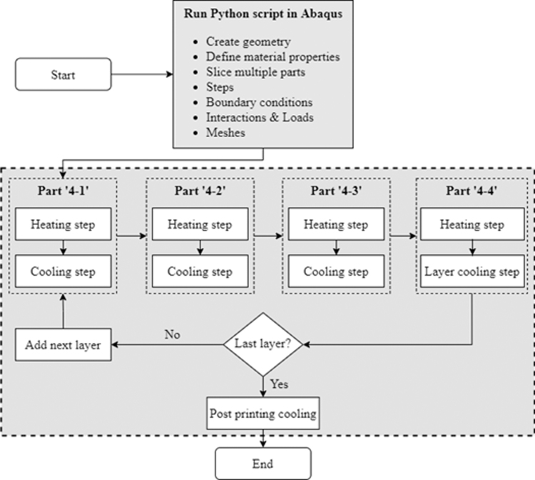
The above four steps are repeated for each layer until finish manufacturing of the two parts. At the end of the computational process modeling, there is a final cooling step for the two prisms to cool to room temperature. The process modeling of the four prisms consists of the following steps and is shown in Figure 2:
FIG. 2.
Flowchart for the four-part thermomechanical PBF-LB process modeling. PBF-LB, laser beam powder bed fusion.
-
1.
The heating step for the first part “4-1” (Fig. 1d) to be manufactured for a period of heating step time tm.
-
2.
The first part “4-1” cooling step for a period of cooling time interval ti. This step is after manufacturing of the active layer of the first part “4-1” and before melting of the active layer of another three parts. The first part “4-1” begins to cool from the beginning of this cooling step.
-
3.
The heating step for the second part “4-2” (Fig. 1d) for a period of heating step time tm.
-
4.
The second part cooling step for a period of cooling time interval ti. The second part starts to cool from the beginning of this step.
-
5.
The heating step for the third part “4-3” (Fig. 1d) for a period of time tm.
-
6.
The third part cooling step for a period of cooling time interval ti. The third part begins to cool from the beginning of this step.
-
7.
The fourth part “4-4” (Fig. 1d) heating step for a period of time tm.
-
8.
Layer cooling step for a period of time tc, where all the four parts continue to cool through this layer cooling step.
The above steps are repeated for each layer until completing the manufacturing process of all the four parts on the build plate, and then, all the parts are cooled to room temperature during the final postprinting process.
The effect of the number of parts per build on the temperature of the part is investigated via the temperature evolution at the central node of the part, which is labeled with “N1” in Figure 1a. To investigate the influence of the number of parts in a single build on the temperature of the build plate, temperature evolution at the node labeled “N2” (Fig. 1b) on the build plate is monitored for each simulation.
Thermal mechanisms
For the computational laser beam heating process in PBF-LB, the layer-by-layer approach with an equivalent heat source is used in this work. The governing equation for the computational FEM using ABAQUS is given based on the energy balance:
| (1) |
where ρ represents the density, Cp for specific heat, T for temperature, t for time, Q for power density of laser heating, L for latent heat of fusion, and q for heat flux. The liquid fraction f is assumed to be a linear function of temperature as follows39:
| (2) |
where TS and TL are the solidus and liquidus temperature, respectively.
The uniformly distributed power density applied on each layer in the FEM simulation can be determined based on the build process parameters40:
| (3) |
where A is the heat source absorption coefficient, P is the laser beam power, ds is the heat source spot diameter, dm is the melt pool depth, and H is the hatch spacing.
The heating step time for each layer is defined as follows27:
| (4) |
where vs is the laser beam scanning speed during the material melting process.
The part cooling time interval ti can be calculated based on the total scanning length of the active layer of a part and the laser beam scanning speed and can be defined as follows27:
| (5) |
where Lt is the total scanning length of the specific active layer of part.
The ILDT for each layer is defined as the sum of part heating step time tm, cooling time interval ti, and layer cooling step time tc of all parts during manufacturing of a specific layer. As the cross-sectional area of the prism decreases along the build z direction, the ILDT per layer decreases with the number of layers deposited. For different numbers of the prism manufacturing per build, the ILDTs also differ from each other,13 as shown in Table 2.
Table 2.
The Interlayer Dwell Time for Different Numbers of Prism Printing
| Number of prisms | ILDT of first layer (s) | Total ILDT of a part (s) |
|---|---|---|
| 1 | 18.3 | 5572.71 |
| 2 | 26.6 | 6145.42 |
| 4 | 43.2 | 7290.84 |
ILDT, interlayer dwell time.
Boundary conditions
In this multipart process modeling work, the thermal transfer mechanisms include heat conduction to the previously deposited material and the build plate, heat conduction from the solidified material to the surrounding powder bed, heat radiation and convection from the top surface of the active layer to the surrounding atmosphere (chamber) until the next layer is added. The initial predefined temperature of the whole powder bed model is set to be 293 K.41 Details in terms of the thermal transfer mechanisms can be found in the authors' previous publications.32,33
The heat flux due to conduction can be formulated as follows42:
| (6) |
where k is the temperature-dependent thermal conductivity of the material. The heat radiation at the top surface of the active layer is considered in the modeling before the next layer is added32:
| (7) |
where is the heat flux due to the active layer radiation, ɛ is the emissivity, σs is the Stefan–Boltzmann constant, Ts is the surface temperature of the part, and Tr is the build chamber temperature.43 Here the emissivity of the active layer surface ɛ and the Stefan–Boltzmann's constant σs were set as 0.3544 and 5.669 × 10⁻⁸ W/(m2K4),45 respectively.
The heat flux between the solidified material and the surrounding powder bed can be formulated as follows32,33:
| (8) |
where h is the heat transfer coefficient.44
Mechanical mechanisms
The equilibrium for the mechanical analysis is given by the following:
| (9) |
where σ is the stress tensor. The mechanical constitutive law for the elastic problem is defined as follows:
| (10) |
where C is material stiffness tensor and ɛe is the elastic strain. The total strain rate can be represented as follows:
| (11) |
where ɛTotal, ɛp, and ɛT are the total, the plastic, and the thermal strain tensor, respectively. The thermal strain component is given by the following:
| (12) |
where α is the coefficient of thermal expansion.
Material properties and process parameters
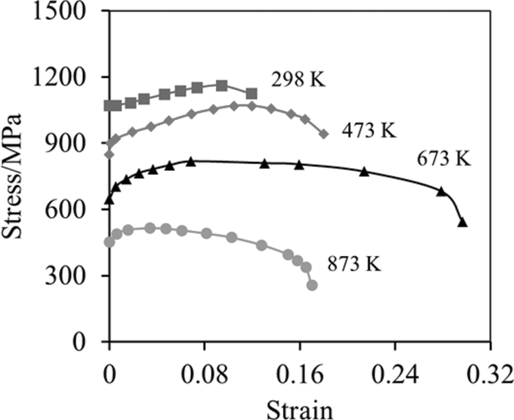
The temperature-dependent Ti-6Al-4V material properties are utilized for the build plate and parts.31–33,46 The temperature-dependent plastic property with isotropic hardening law is original from Ahn et al.,47 as shown in Figure 3. The volumetric energy density applied at each layer of powder bed is 1.59 × 10¹⁰ J/m3. According to Ali et al.,48 the minimum energy density to manufacture nearly fully dense Ti-6Al-4V components is 5.54 × 10⁹ J/m3. The process parameters for the computational multipart PBF-LB modeling are summarized in Table 3. The proposed process parameters are the same as what were used by Wang et al.,49 Zhao et al.,50 and Shrestha and Chou.51 They proved to be sufficient for manufacturing dense Ti-6Al-4V components.
FIG. 3.
Temperature-dependent tensile behavior of Ti-6Al-4V material applied for PBF-LB process modeling.47
Table 3.
Process Parameters Applied in Multipart Laser Beam Powder Bed Fusion Modeling
| Build plate size (m) | 0.25 × 0.25 × 0.025 | |
| Tbp | Build plate preheat temperature (K) | 293 |
| Lh | Layer height (mm) | 0.48 |
| tm | Heating step time each layer (s) | 0.000167 |
| Volumetric energy density (J/m3) | 1.59 × 10¹⁰ | |
| tc | Cooling step time each layer (s) | 40 |
| P | Laser beam power (W) | 95 |
| A | Heat source absorption coefficient | 0.4 |
| R | Heat source spot radium (mm) | 0.05 |
| vs | Laser scanning speed (m/s) | 0.6 |
| ɛ | Emissivity | 0.35 |
| h | Heat transfer coefficient (w/m2/K) | 12.7 |
| L | Latent heat of fusion (kJ/kg) | 370 |
Results and Discussion
The effect of batch size on temperature of the build plate
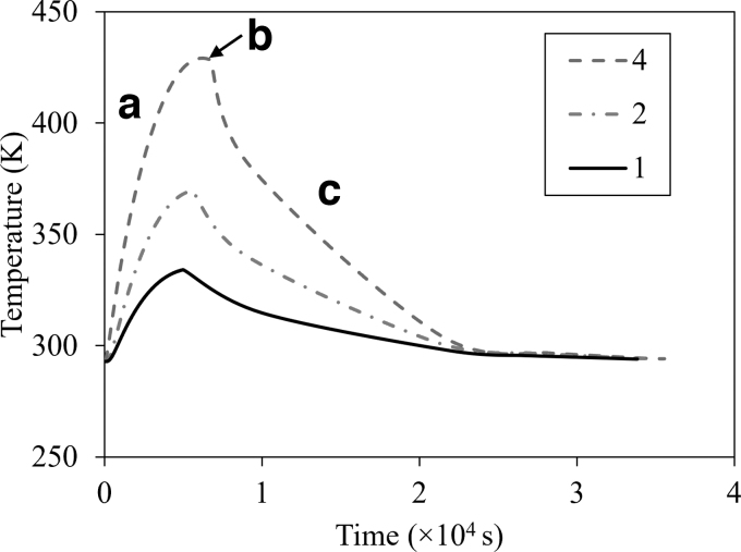
The temperature history of the build plate influences the temperature history and RS of PBF-LB-manufactured parts.52,53 Therefore, the temperature evolution with time at the N2 node (Fig. 1b) of the build plate is computationally investigated for the single-prism, two-prism, and four-prism PBF-LB manufacturing (Fig. 4). To accurately predict temperature evolution during the actual printing, the dimension of the computational build plate is the same as that of a real PBF-LB hardware.9
FIG. 4.
Effect of the number of the same prisms (1, 2, and 4) per build on temperature evolution of the build plate with time. (a) Manufacturing process, (b) peak temperature, and (c) postprinting cooling process.
In this work, the sample location effect on the temperature evolution of the build plate was not investigated. For different numbers of prisms, all the N2 nodal temperature histories follow the same overall trend. The temperature of the build plate gradually increases with the deposition of layers during the manufacturing process (Fig. 4a) before reaching the peak temperature after the last layer of powder is deposited (Fig. 4b), and then monotonically decreases to room temperature during the postprinting process (Fig. 4c).
A similar process of temperature evolution of the build plate was observed in experimentation.54 Figure 4 indicates that the larger the number of the same parts printed in the same build plate, the significantly higher temperature of the build plate. The peak temperature at the N2 node of the build plate for the two-prism (369.64 K) and four-prism (420.03 K) PBF-LB during the entire manufacturing process is 10.62% and 25.70% higher than that of the single-prism (334.15 K) PBF-LB printing. Processes with additional parts apply more energy and thus resulting in more heat to be conducted to the previously solidified layers and significantly increasing the overall temperature of the powder bed in a single build.
The effect of batch size on temperature of part
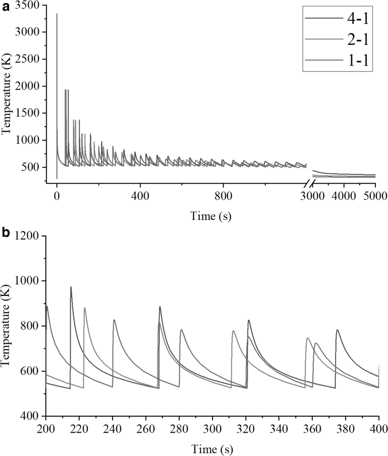
To investigate the effect of the number of samples per build on the temperature history of parts, the temperature evolution with time at the central node of N1 (Fig. 1a) of the parts “1-1,” “2-1,” and “4-1” (Fig. 1) is plotted (Fig. 5). To make the temperature evolutions more feasible to compare for different numbers of part printing, the time zero in Figure 5 is set to be the time point when the middle layer of the part (where the N1 node locates, Fig. 1a) is printed.
FIG. 5.
Temperature evolution with time at the central node N1 for different numbers (1, 2, and 4) of prism printing. (a) Original figure and (b) magnified figure.
For all the modeling cases, the repeated deposition, melting, and solidification of the subsequent layers of material cause periodic fluctuations of nodal temperature at N1, but the overall trend of temperature is decreasing with time. The ILDT, including melting time and cooling time for each layer, is different for different numbers of part printing. The larger the number of part printing at the same build plate, the larger the ILDT, which causes a larger oscillation interval of temperature (Fig. 5).
It can be seen from Figure 5a that the overall trend in temperature with time is consistent for all cases, but with different magnitudes of temperature. Figure 5b indicates that the overall temperature and temperature increment of the four-prism printing are always the highest compared with that of the two-prism and single-prism manufacturing for each layer. For the multipart PBF-LB manufacturing, more energy (e.g., four times for the four-part build compared with the single-part manufacturing) is input into the powder bed that results in a higher temperature than the single-part printing.
The upward slope (for the heating process) for the three computational models is identical, due to the same process parameters being used (Table 3). However, the downward slope (for the cooling process) is different for the different numbers of part manufacturing, for example, the downward slope for the four-part build “4-1” is lower than that of the single-part build “1-1” (Fig. 5).
To investigate the influence of the number of parts on the temperature of prism, the computational modeling results of temperature contours for the single prism, two prisms, and four prisms after completing printing and cooling for 40 s are demonstrated in Figure 6. For all the temperature fields with different numbers of prisms, the top areas of the prisms always have a higher temperature than that of the bottom of the part. This is because the heat energy is input from the top layer of parts and the thermal dissemination is mainly from the top to the bottom of the parts.
FIG. 6.
Temperature contours of prisms after completing printing and cooling for 40 s for different numbers of prism modeling. (a) Single prism, (b) two prisms, and (c) four prisms.
The overall part temperature of printing setup “4-1” is significantly higher than that of the setup “1-1.” The temperature contours indicate that part temperature is higher when a greater number of prisms are printed on a common base plate. This phenomenon was also found by Yılmaz and Kayacan.9 After the manufacturing process is complete and cooling for 40 s, the temperature of four-prism and two-prism printing is 2.97% and 8.11% than the single-prism manufacturing, respectively.
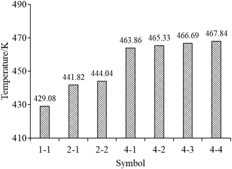
The higher temperature of prisms for the larger number of samples is caused by more energy input into the powder bed per build. While for the two-prism and four-prism manufacturing on the same build plate, the effect of the prism printing order on temperature is found to be minimum (i.e., <0.85% temperature difference, Fig. 6b, c), which indicates that the prisms and powder bed tend to form a uniform temperature distribution in the same build plate during PBF-LB manufacturing.
To quantify the temperature difference for different numbers of prism PBF-LB manufacturing, the peak temperatures of parts after completing printing and cooling for 40 s for different numbers of the prisms are summarized in Figure 7. It can be seen from both the temperature contours (Fig. 6) and temperature magnitudes (Fig. 7) that the more prisms manufacturing at the same build plate, the higher the peak temperature is of the part after build completion and cooling for 40 s.
FIG. 7.
Computational modeling results of peak temperature statistics of parts after completing printing and cooling for 40 s for different numbers and different printing orders of prisms in a single build.
For instance, the temperature of four-prism printing the part “4-1” is 8.11% higher than that of the single-prism printing part “1-1” (Figs. 1 and 7). In addition, for the four-prism manufacturing, the lowest peak temperature (463.86 K for the part “4-1”) of part is 0.85% lower than that of the highest temperature (467.84 K for the part “4-4”), which also indicates that the part printing order included in this model in the same build plate has a minimum effect on the temperature of parts. The conclusion from the temperature histogram (Fig. 7) is consistent with the temperature contours of parts (Fig. 6).
The effect of batch size on RS
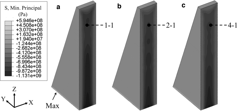
The final RS refers to RS of part after the build is completed and has been allowed to cool for 6 h to room temperature. Figure 8 shows the final minimum principal RS contours of the parts “1-1,” “2-1,” and “4-1” (Fig. 1), which represent the single-prism, two-prism, and four-prism manufacturing, respectively. It can be seen that, regardless of the number of part printing at the same build plate, the surfaces of prisms have tensile RS, while stresses at the central areas of prisms are compressive, which is in good agreement with the results of simulation and experiment by other studies.23,28,32
FIG. 8.
The final minimum principal RS contours for different numbers of prism printing at the same build plate. (a) Single prism, (b) two prisms, and (c) four prisms. RS, residual stress.
For all the computational modeling cases, the largest tensile RS occurs at the bottom of the part (i.e., the interface between the part and the build plate), which is also found elsewhere.4,31 The single-prism modeling (Fig. 8a) has a marginally larger maximum stress (594.63 MPa) than the two-prism (577.93 MPa) and four-prism modeling (558.90 MPa), which indicates that the multipart build in the same build plate is beneficial for mitigating the RS of parts.
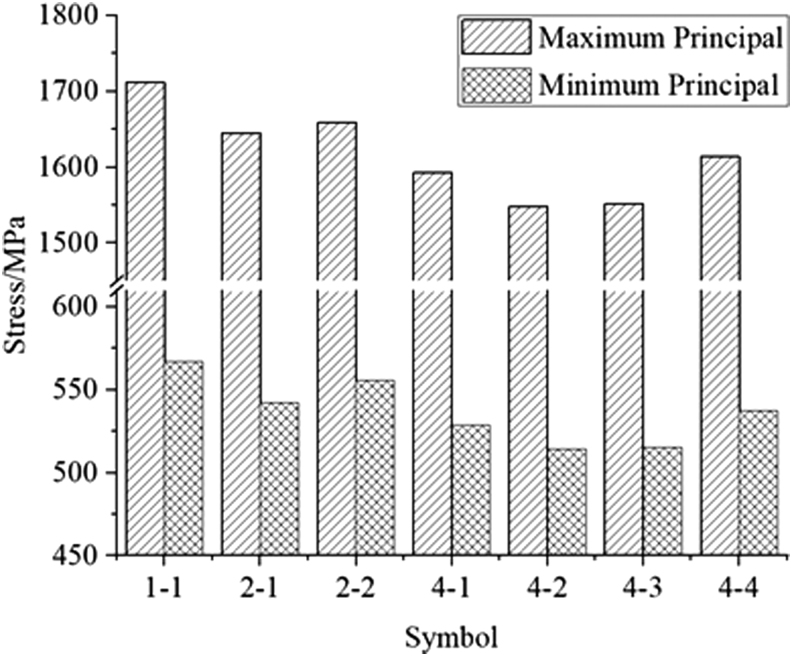
The final maximum RS (maximum principal stress and minimum principal stress) of the single-prism, two-prism, and four-prism manufacturing is shown in Figure 9. Both the maximum principal RS and the minimum principal RS results (Fig. 9) indicate that an increase in the number of parts at the same build plate reduces the maximum RS magnitude of parts. The maximum principal RS for the single-prism, two-prism, and four-prism modeling is 1711.30, 1658.42, and 1613.89 MPa, respectively.
FIG. 9.
The final finite element-predicted peak RS (maximum principal stress and minimum principal stress) for different numbers and printing orders of prism modeling.
The thermal behaviors of parts (Figs. 6 and 7) during the PBF-LB manufacturing influence the final RS of the parts. The decrease of RS of parts with increasing the number of prisms is because the temperature of the build plate increases (Fig. 4) with the number of prism printing in the same build plate, which results in a potentially lower thermal gradient and thus a lower RS of parts.55
The effects of part printing order and location on RS
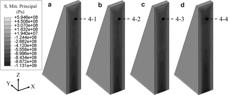
Figure 10 shows the computational modeling results of the minimum principal RS contours of the four-prism modeling with different printing orders within the same build plate. Similar RS distributions of prisms are formed for the different printing orders, assumed to be caused by similar temperature histories (Figs. 6 and 7). Both the final maximum principal RS magnitudes (Fig. 9) and RS contours (Fig. 10) of prisms for the different printing orders indicate that the printing order of samples on the same build plate has a minimum effect on the RS of samples. This conclusion agrees with other studies.9
FIG. 10.
Effect of part printing order on RS contours in four-prism build. (a) The part ‘4-1’, (b) the prism ‘4-2’, (c) the prism ‘4-3’, and (d) the prism ‘4-4’.
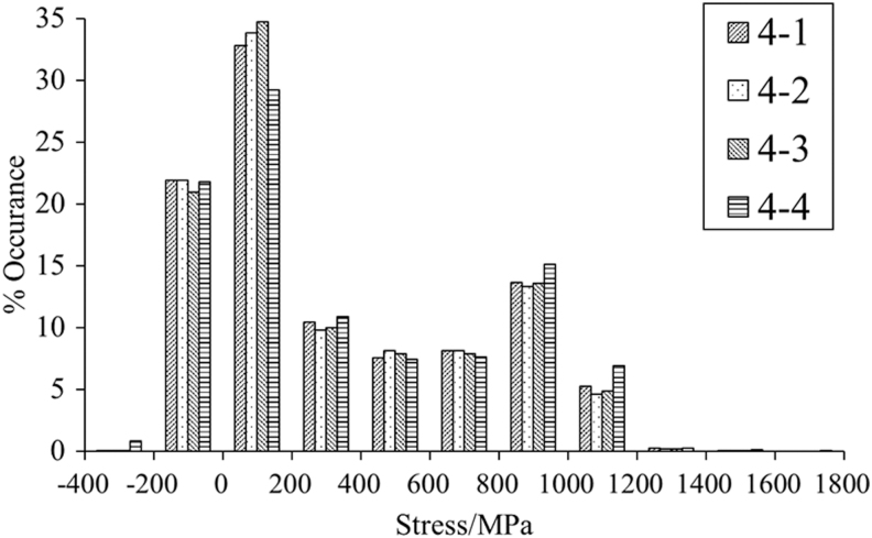
Figure 11 illustrates the histogram distribution statistics of the maximum principal stress of prisms for the four-prism printing with different printing orders at the same build plate. For all cases, RS for most regions within the prisms is low—ranging from −200 to 200 MPa (Fig. 11). For the four-prism printing, the prisms located toward the edges of the build plate (e.g., the part “4-4”) have a wider RS distribution compared with other prisms in the same build plate.
FIG. 11.
Histograms and distributions of the peak maximum principal stress statistics for four-prism printing with different printing orders.
It is noted that the prisms located near the central areas of the build plate (the prisms “4-2” and “4-3,” Fig. 1) have comparatively lower RS than that of the prisms located near the edges of the build plate (the parts “4-1” and “4-4,” Fig. 1), which is in consistence with a study.9 This is assumed to be caused by the outer parts being connected to cooler regions of the build plate than the centrally located parts, and thus, the cooling rate of parts at the edges of the build plate is higher than that at the center of the build plate.9
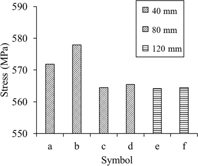
Figure 12 shows the minimum RS for a two-prism build with different spacings (40, 80, and 120 mm). The results indicate that for the 40 and 80 mm part spacing manufacturing, the larger the spacing between parts, the lower the RS that resulted. For part spacing larger than 80 mm, it has an insignificant effect on RS (Fig. 12c–f). Note that in the multipart process modeling, the heat conduction between the solid part and the surrounding powder material is simplified as the part-interface convection.32,33
FIG. 12.
Computational modeling results of the effect of part spacing on RS for the two-prism printing. (a) Prism “2-1” with a part spacing of 40 mm. (b) Prism “2-2” with a part spacing of 40 mm. (c) Prism “2-1” with a part spacing of 80 mm. (d) Prism “2-2” with a part spacing of 80 mm. (e) Prism “2-1” with a part spacing of 120 mm. (f) Prism “2-2” with a part spacing of 120 mm.
Therefore, the specific part heating and cooling processes influenced by the surrounding parts are not considered in the multipart manufacturing in this work. In future, the convection approximation (i.e., the heat sink temperature and the depth of surrounding powder) should be further modified for multipart build in PBF-LB process modeling.
For parts at exactly the same location of the build plate, but with different numbers of part fabrication per build (i.e., the part “2-1” with a part spacing of 120 mm and the part “4-1,” the part “2-2” with a part spacing of 120 mm and the part “4-4”), the lower RS of part is obtained for the larger number of part build (Figs. 9 and 12). This further proves that the multipart build is beneficial for mitigating RS. This work investigated part spacing effects on RS by using a two-part build. As the number of parts can also influence RS, the part spacing effect on RS in multiple (over two) parts should also be investigated in future work. This also provides guidance for the design of builds for experimental measurements of RS, demonstrating that repeated builds of single-part-only builds may give more repeatable experimental RS results than a single build with multiple parts.
Conclusions
In summary, the computational thermomechanical FEM framework for macroscale multipart build by single laser beam PBF-LB for Ti-6Al-4V is presented. The effects of the number of prisms per build, part spacing, and part location at the build plate on temperature and RS of parts are predicted in multipart PBF-LB manufacturing. The key conclusions of this work are as follows:
Coupled thermomechanical process modeling capability was developed for multipart PBF-LB manufacturing for predicting temperature and RS of Ti-6Al-4V material.
The temperature of the build plate and part by different numbers of part manufacturing is quantitatively compared. The more samples manufactured in a single build in PBF-LB, the higher the temperature will be of both the part and the build plate. The predicted temperature of the build plate increases with time during the multipart manufacturing process.
A multipart build is predicted to produce a lower RS than that of the single-part build and the maximum RS of parts decreases with the number of (same) parts per build.
In multipart PBF-LB build, nonuniform stress profiles in parts at the same build plate are obtained. Parts located at the central areas of the build plate are predicted to have a lower RS than parts that are located at the edges of the build plate in multipart build.
The larger the part spacing in multipart PBF-LB manufacturing, the lower the RS the part resulted before stabilization with the part spacing of 80 mm.
For multipart printing, the largest stress occurs at the interface of the part and the build plate, and tensile stress occurs at the surface areas of parts while compressive stress forms at the central area of the part, which is identical with the single-part PBF-LB manufacturing.
Acknowledgments
The authors thank Catrin Mair Davies for providing valuable comments on the article. For the purpose of Open Access, the author has applied a CC BY public copyright license to any author-accepted article version arising from this submission. The authors wish to acknowledge the Irish Centre for High-End Computing (ICHEC) for the provision of computational facilities and support.
Nomenclature
- ρ
Density of solid, kg/m3
- Cp
Specific heat, J/(kgK)
- L
Latent heat of fusion, J/kg
- q
Heat flux, W/m2
- Q
Power density, W/m3
- A
Heat source absorption coefficient
- P
Laser beam power, W
- ds
Laser beam spot diameter, m
- dm
Melt pool depth, m
- H
Hatch spacing, m
- vs
Laser scanning speed, m/s
- k
Thermal conductivity of solid, W/(m2K)
Temperature gradient, K
Conduction heat flux, W/m2
Convection heat flux, W/m2
- h
Heat transfer coefficient, W/(m2K)
- Tr
Chamber temperature, K
Radiation heat flux, W/m2
- ɛ
Emissivity coefficient
- σs
Stefan–Boltzmann constant, W/(m2K4)
- σ
Stress, MPa
- ɛp
Plastic strain
- ɛt
Thermal strain
- α
Thermal expansion coefficient, 1/K
Author Disclosure Statement
No competing financial interests exist.
Funding Information
This research is funded by the Irish Research Council (GOIPG/2018/2488) under the Government of Ireland Postgraduate Programme. The work is also supported, in part, by a research grant from the Science Foundation Ireland (SFI) under Grant Number 16/RC/3872 and is cofunded under the European Regional Development Fund.
References
- 1. Harun WSW, Kamariah MSIN, Muhamad N, et al. A review of powder additive manufacturing processes for metallic biomaterials. Powder Technol 2018;327:128–151. [Google Scholar]
- 2. Criales LE, Özel T. Temperature profile and melt depth in laser powder bed fusion of Ti-6Al-4V titanium alloy. Prog Addit Manuf 2017;2:169–177. [Google Scholar]
- 3. Parry LA, Ashcroft IA, Wildman RD. Geometrical effects on residual stress in selective laser melting. Addit Manuf 2019;25:166–175. [Google Scholar]
- 4. Cheng B, Shrestha S, Chou K. Stress and deformation evaluations of scanning strategy effect in selective laser melting. Addit Manuf 2016;12:240–251. [Google Scholar]
- 5. Pant P, Proper S, Luzin V, et al. Mapping of residual stresses in as-built Inconel 718 fabricated by laser powder bed fusion: A neutron diffraction study of build orientation influence on residual stresses. Addit Manuf 2020;36:101501. [Google Scholar]
- 6. Ganeriwala RK, Strantza M, King WE, et al. Evaluation of a thermomechanical model for prediction of residual stress during laser powder bed fusion of Ti-6Al-4V. Addit Manuf 2019;27:489–502. [Google Scholar]
- 7. Dunbar AJ, Denlinger ER, Gouge MF, et al. Experimental validation of finite element modeling for laser powder bed fusion deformation. Addit Manuf 2016;12:108–120. [Google Scholar]
- 8. Williams RJ, Piglione A, Rønneberg T, et al. In situ thermography for laser powder bed fusion: Effects of layer temperature on porosity, microstructure and mechanical properties. Addit Manuf 2019;30:100880. [Google Scholar]
- 9. Yılmaz N, Kayacan MY. Effect of single and multiple parts manufacturing on temperature-induced residual stress problems in SLM. Inte J Mater Form 2021;14:407–419. [Google Scholar]
- 10. Mahmoudi M. Mechanical properties and microstructural characterization of selective laser melted 17-4 PH stainless steel. Rapid Prototyp J 2017;23:280–294. [Google Scholar]
- 11. Mohr G, Altenburg SJ, Hilgenberg K. Effects of inter layer time and build height on resulting properties of 316L stainless steel processed by laser powder bed fusion. Addit Manuf 2020;32:101080. [Google Scholar]
- 12. DebRoy T, Wei HL, Zuback JS, et al. Additive manufacturing of metallic components—Process, structure and properties. Prog Mater Sci 2018;92:112–224. [Google Scholar]
- 13. Yadollahi A, Shamsaei N. Additive manufacturing of fatigue resistant materials: Challenges and opportunities. Int J of Fatigue 2017;98:14–31. [Google Scholar]
- 14. Lee Y, Bandari Y, Nandwana P, et al. Effect of interlayer cooling time, constraint and tool path strategy on deformation of large components made by laser metal deposition with wire. Appl Sci 2019;9:5115. [Google Scholar]
- 15. Denlinger ER, Heigel JC, Michaleris P, et al. Effect of inter-layer dwell time on distortion and residual stress in additive manufacturing of titanium and nickel alloys. J Mater Process Tech 2015;215:123–131. [Google Scholar]
- 16. Yadollahi A, Shamsaei N, Thompson SM, et al. Effects of process time interval and heat treatment on the mechanical and microstructural properties of direct laser deposited 316L stainless steel. Mater Sci Eng A 2015;644:171–183. [Google Scholar]
- 17. Foster BK, Beese AM, Keist JS, et al. Impact of interlayer dwell time on microstructure and mechanical properties of nickel and titanium alloys. Metall Mater Trans A 2017;48:4411–4422. [Google Scholar]
- 18. Li R, Xiong J. Influence of interlayer dwell time on stress field of thin-walled components in WAAM via numerical simulation and experimental tests. Rapid Prototyp J 2019;25:1433–1441. [Google Scholar]
- 19. Ge J, Lin J, Fu H, et al. Tailoring microstructural features of wire arc additive manufacturing 2Cr13 part via varying inter-layer dwelling time. Mater Lett 2018;232:11–13. [Google Scholar]
- 20. Yakout M, Elbestawi MA, Veldhuis SC. On the characterization of stainless steel 316L parts produced by selective laser melting. Int J Adv Manuf Technol 2018;95:1953–1974. [Google Scholar]
- 21. Robinson J, Ashton I, Fox P, et al. Determination of the effect of scan strategy on residual stress in laser powder bed fusion additive manufacturing. Addit Manuf 2018;23:13–24. [Google Scholar]
- 22. Fitzgerald E, Everhart W. The effect of location on the structure and mechanical properties of selective laser melted 316 L stainless steel. Proceedings of the 26th Annual International Solid Freeform Fabrication Symposium. 2016;574–583. [Google Scholar]
- 23. Williams RJ, Davies CM, Hooper PA. A pragmatic part scale model for residual stress and distortion prediction in powder bed fusion. Addit Manuf 2018;22:416–425. [Google Scholar]
- 24. Zhang Y, Chen Q, Guillemot G, et al. Numerical modelling of fluid and solid thermomechanics in additive manufacturing by powder-bed fusion: Continuum and level set formulation applied to track- and part-scale simulations. Comptes Rendus Mécanique 2018;346:1055–1071. [Google Scholar]
- 25. Yang Y, Allen M, London T, et al. Residual strain predictions for a powder bed fusion inconel 625 single cantilever part. Integr Mater Manuf Innov 2019;8:294–304. [Google Scholar]
- 26. Li C, Guo Y, Fang X, et al. A scalable predictive model and validation for residual stress and distortion in selective laser melting. CIRP Annals 2018;67:249–252. [Google Scholar]
- 27. Zhang Y, Guillemot G, Bernacki M, et al. Macroscopic thermal finite element modeling of additive metal manufacturing by selective laser melting process. Comput Methods Appl Mech Eng 2018;331:514–535. [Google Scholar]
- 28. Prabhakar P, Sames WJ, Dehoff R, et al. Computational modeling of residual stress formation during the electron beam melting process for Inconel 718. Addit Manuf 2015;7:83–91. [Google Scholar]
- 29. Wu AS, Brown DW, Kumar M, et al. An experimental investigation into additive manufacturing-induced residual stresses in 316L stainless steel. Metall Mater Trans A 2014;45:6260–6270. [Google Scholar]
- 30. Ramos D, Belblidia F, Sienz J. New scanning strategy to reduce warpage in additive manufacturing. Addit Manuf 2019;28:554–564. [Google Scholar]
- 31. Zhang W, Tong M, Harrison NM. Scanning strategies effect on temperature, residual stress and deformation by multi-laser beam powder bed fusion manufacturing. Addit Manuf 2020;36:101507. [DOI] [PMC free article] [PubMed] [Google Scholar]
- 32. Zhang W, Tong M, Harrison NM. Resolution, energy and time dependency on layer scaling in finite element modelling of laser beam powder bed fusion additive manufacturing. Addit Manuf 2019;28:610–620. [Google Scholar]
- 33. Zhang W, Tong M, Harrison NM. Data on a computationally efficient approximation of part-powder conduction as surface free convection in powder bed fusion process modelling. Data Brief 2019;27:104559. [DOI] [PMC free article] [PubMed] [Google Scholar]
- 34. Pauzon C, Forêt P, Hryha E, et al. Argon-helium mixtures as Laser-Powder Bed Fusion atmospheres: Towards increased build rate of Ti-6Al-4V. J Mater Process Tech 2020;279:116555. [Google Scholar]
- 35. Bidare P, Bitharas I, Ward RM, et al. Fluid and particle dynamics in laser powder bed fusion. Acta Mater 2018;142:107–120. [Google Scholar]
- 36. Strantza M, Ganeriwala RK, Clausen B, et al. Effect of the scanning strategy on the formation of residual stresses in additively manufactured Ti-6Al-4V. Addit Manuf 2021;45:102003. [Google Scholar]
- 37. Levkulich NC, Semiatin SL, Gockel JE, et al. The effect of process parameters on residual stress evolution and distortion in the laser powder bed fusion of Ti-6Al-4V. Addit Manuf 2019;28:475–484. [Google Scholar]
- 38. de Oliveira AR, de Oliveira VF, Teixeira JC, et al. Investigation of the build orientation effect on magnetic properties and Barkhausen Noise of additively manufactured maraging steel 300. Addit Manuf 2021;38:101827. [Google Scholar]
- 39. Bayat M, Mohanty S, Hattel JH. A systematic investigation of the effects of process parameters on heat and fluid flow and metallurgical conditions during laser-based powder bed fusion of Ti6Al4V alloy. Int J Heat Mass Transf 2019;139:213–230. [Google Scholar]
- 40. Li C, Liu JF, Guo YB. Prediction of residual stress and part distortion in selective laser melting. Procedia CIRP 2016;45:171–174. [Google Scholar]
- 41. Li H, Ramezani M, Chen Z, et al. Effects of process parameters on temperature and stress distributions during selective laser melting of Ti-6Al-4V. Trans Indian Inst Met 2019;72:3201–3214. [Google Scholar]
- 42. Li C, Fu CH, Guo YB, et al. A multiscale modeling approach for fast prediction of part distortion in selective laser melting. J Mater Process Tech 2016;229:703–712. [Google Scholar]
- 43. Zhao X, Iyer A, Promoppatum P, et al. Numerical modeling of the thermal behavior and residual stress in the direct metal laser sintering process of titanium alloy products. Addit Manuf 2017;14:126–136. [Google Scholar]
- 44. Masoomi M, Thompson SM, Shamsaei N. Laser powder bed fusion of Ti-6Al-4V parts: Thermal modeling and mechanical implications. Int J Mach Tools Manuf 2017;118–119(Suppl. C):73–90. [Google Scholar]
- 45. Khairallah SA, Anderson AT, Rubenchik A, et al. Laser powder-bed fusion additive manufacturing: Physics of complex melt flow and formation mechanisms of pores, spatter, and denudation zones. Acta Mater 2016;108:36–45. [Google Scholar]
- 46. Protasov CE, Khmyrov RS, Grigoriev SN, et al. Selective laser melting of fused silica: Interdependent heat transfer and powder consolidation. Int J Heat Mass Transf 2017;104:665–674. [Google Scholar]
- 47. Ahn J, He E, Chen L, et al. Prediction and measurement of residual stresses and distortions in fibre laser welded Ti-6Al-4V considering phase transformation. Mater Des 2017;115:441–457. [Google Scholar]
- 48. Ali H, Ghadbeigi H, Mumtaz K. Effect of scanning strategies on residual stress and mechanical properties of Selective Laser Melted Ti6Al4V. Mater Sci Eng A 2018;712:175–187. [DOI] [PMC free article] [PubMed] [Google Scholar]
- 49. Wang M, Wu Y, Lu S, et al. Fabrication and characterization of selective laser melting printed Ti–6Al–4V alloys subjected to heat treatment for customized implants design. Prog Nat Sci Mater Int 2016;26:671–677. [Google Scholar]
- 50. Zhao C, Parab ND, Li X, et al. Critical instability at moving keyhole tip generates porosity in laser melting. Science 2020;370:1080. [DOI] [PubMed] [Google Scholar]
- 51. Shrestha S, Chou K. Single track scanning experiment in laser powder bed fusion process. Procedia Manuf 2018;26:857–864. [Google Scholar]
- 52. Malý M, Höller C, Skalon M, et al. Effect of Process Parameters and High-Temperature Preheating on Residual Stress and Relative Density of Ti6Al4V Processed by Selective Laser Melting. Materials (Basel, Switzerland) 2019;12:930. [DOI] [PMC free article] [PubMed] [Google Scholar]
- 53. Lei Y, Xiong J, Li R. Effect of inter layer idle time on thermal behavior for multi-layer single-pass thin-walled parts in GMAW-based additive manufacturing. Int J Adv Manuf Technol 2018;96:1355–1365. [Google Scholar]
- 54. Lu X, Lin X, Chiumenti M, et al. Finite element analysis and experimental validation of the thermomechanical behavior in laser solid forming of Ti-6Al-4V. Addit Manuf 2018;21:30–40. [Google Scholar]
- 55. Ali H, Ma L, Ghadbeigi H, et al. In-situ residual stress reduction, martensitic decomposition and mechanical properties enhancement through high temperature powder bed pre-heating of Selective Laser Melted Ti6Al4V. Mater Sci Eng A 2017;695:211–220. [Google Scholar]


