

Abstract
An in situ needle manipulation technique used by physicians when performing spinal injections is modeled to study its effect on needle shape and needle tip position. A mechanics-based model is proposed and solved using finite element method. A test setup is presented to mimic the needle manipulation motion. Tissue phantoms made from plastisol as well as porcine skeletal muscle samples are used to evaluate the model accuracy against medical images. The effect of different compression models as well as model parameters on model accuracy is studied, and the effect of needle-tissue interaction on the needle remote center of motion is examined. With the correct combination of compression model and model parameters, the model simulation is able to predict needle tip position within submillimeter accuracy.
Index Terms—: Medical Robots and Systems, Surgical Robotics: Steerable Catheters/Needles
I. Introduction
Spinal injection is a percutaneous procedure for diagnosis and treatment of back and neck pain. During the procedure, the physician advances a spinal needle and injects diagnostic or therapeutic agent once the needle reaches the anatomical target [1]. Intraoperative imaging, such as fluoroscopy and computed tomography (CT) are routinely used as visual feedback to the physician due to their wide availability; however, ionizing radiation exposure puts both the patients and the physicians at higher risk of developing cancer, albeit the presence of dose-reducing measures [2], [3]. Spinal needles are typically made from stainless steel and are sized with diameter of 18 gauge (1.2mm) or smaller [1], [4], making them flexible and subject to shape deformation.
Many spinal injection procedures require targeting of submillimeter nerves and thin anatomical spaces. Common targets are often surrounded by vulnerable structures such as major arteries and veins, increasing the chance of complications due to needle misplacement [5]. Difficulties in accessing and visualizing these regions of human body necessitate the highest spatial and contrast image resolution and image guidance accuracy to ensure accurate and safe drug delivery, which is best provided by magnetic resonance imaging (MRI).
The use of robotic devices in the magnetic resonance (MR) environment to perform percutaneous interventions is a promising option. The robot can directly operate on the patient based on the acquired MRI scans, allowing MRI to serve as both a diagnostic tool and a guidance system for the robot [6]. A wide variety of MR-compatible robots for needle-based interventions have been developed for procedures such as prostate therapy [7], [8], [9], [10], [11], neurosurgery [12], [13], [14], and joint injections [15], [16]. For example, in [7], [8], Susil et al developed a robot for MRI-guided prostate biopsy, which was further improved by Krieger et al. and the robot is able to achieve better than 2.3mm positional error from the needle tip to the target [9]. Guo et al. developed a hydraulic-driven robot for MRI-guided bilateral stereotactic neurosurgery; the robot’s embedded wireless tracking units are able to continuously localize the robotic instrument under a proper MR tracking sequence [13], [17].
Many aforementioned robotic systems feature a kinematic constraint called the remote center of motion (RCM), about which the robot instrument pivots and translates. For typical laparoscopic surgeries, the RCM is placed about the tool entry point near the patient skin, through which the rigid surgical instrument will operate on the patient anatomical feature of interest while reducing other unnecessary tool-tissue interaction [18]; in fact, such constraint is so common for medical robots that it is considered “homologous to minimally invasive” [19].
However, for needle-based percutaneous procedures, such causality between the presence of an RCM and “minimally invasive” cannot be easily established. Instead of being a pivot point for needle motion, the RCM have simply been used interchangeably with “entry point” for needle insertions [20], [14], [19], [21]. It has been shown that any lateral motion of an inserted flexible needle, either from translation or rotation about an RCM, can cause the needle to compress its surrounding tissue, which in turn deforms the needle itself. Therefore, although the robot might obey an RCM kinematic constraint, the path taken by the needle will be affected by interaction with its surrounding medium, forming its own center of motion (COM) [22].
The notion of an RCM is not completely irrelevant to needle-based procedures. For image-guided spinal injections, when a needle is misplaced, physicians would adjust the inserted needle by bending and laterally translating the needle base, and with the help of the reactive force generated by the soft tissue, they are able to pivot the needle tip onto a better trajectory [23]. Such needle maneuver will not affect the target locations, which are encapsulated by the vertebrae. This needle manipulation roughly resembles a needle base rotational motion about a remote center, and the presence of a virtual RCM can be presumed, albeit at an unspecified location.
Previously, we have presented an MRI-guided lumbar injection robot with targeting accuracy about 1.9 mm [24]; yet for targets like the facet joint, the effective area can be on average much smaller than 2mm [25]. While the robot itself has high motion accuracy, cumulative errors from image registration as well as unmodeled needle-tissue interactions can fail a planned insertion prematurely.
In this work, we present our setup and methodology to study the effect of in situ needle manipulation on the needle shape and tip position. We propose a mechanics-based model that takes into account nonlinear tissue behaviors, and examine the effect of different compression models and material parameters using artificial and animal soft tissues. In addition, we examine the effect and applicability of an RCM in the field of robot-assisted percutaneous needle interventions.
The rest of the paper is organized as follows: Section II introduces a mechanics-based needle-tissue interactions model, and experiment methods to verify the proposed model. Section III presents results from material testing, image registration, as well as finite element method (FEM) simulation accuracy of the model against CT scans. A discussion on the needle RCM and COM is offered in Section III-C. The clinical relevance of the result is summarized in Section III-E. Limitations of current work, as well as future research directions, are laid out in Section III-F.
II. Material and Methods
A. Needle-Tissue Interaction Model
During in situ needle bending for spinal injections, part of the flexible needle is already inserted into the soft skin and muscle tissues, and needle manipulation is applied at the needle base. A schematic of the physical scenario is shown in Figure 1.
Fig. 1:

Schematic of needle interaction with a multilayer medium. Motion applied to the needle base is represented as boundary conditions. Tissue response will differ with different tissue properties. Slope at the needle base forms a needle RCM, while actual needle COM deviates from the RCM due to inherent flexibility of the needle as well as reaction forces generated by the tissue.
The proposed interaction model resembles closely to an Euler-Bernoulli beam with flexible support. The needle, modeled as a homogeneous beam, is initially at rest along the horizontal x–axis and embedded in a multilayer medium, with inserted depth l. Boundary conditions are applied to the needle base such that it is displaced in by db, and tilted by a slope kb. The control distance, sb, separates the point of application of boundary conditions from the point of needle insertion. Due to the flexibility of the needle and the contact with soft tissue, the needle will deform upon base motion, assuming a shape u(x), and the corresponding force generated within the medium is F(x) = ∑ fi(x). If the medium presents no resistance to the needle, i.e. F = 0, the needle would remain straight and intersect the x–axis at an RCM; however, reactive force from the medium will bend the needle, causing it to intersect the x–axis elsewhere, called the needle COM.
The reaction force from each medium, fi(x), will be proportional to the degree of tissue compression. Many have treated the proportionality as a constant, k, which can be regarded as a hyperparameter and the tissue is modeled as a “virtual spring” with a constant coefficient [26]. However, biological soft tissues, such as skin and skeletal muscles, exhibit complex nonlinear stretch-stress behavior, which cannot be characterized effectively using a constant spring model [27].
In order to account for the nonlinear behavior of the tissue, we treat the proportionality function k(x) as the tangent modulus of the material, i.e.
| (1) |
where λc is the compression ratio, and S is the expression for engineering stress (P) or true stress (σ).
| (2) |
| (3) |
The function W in Equations 2 and 3 is the strain energy function of an incompressible hyperelastic material, and λi is the stretch ratio of the tissue in the i-th principal direction. Variable ρ is a Lagrangian multiplier that ensures material incompressibility, and vectors u(i) and v(i) are the i-th eigenvector of the right- and left-stretch tensors, respectively.
Since the tissue can only be compressed in the direction of needle displacement,
| (4) |
where t0 is the initial length of the tissue, so that λc ≤ 1 in the direction of compression. Referring to Figure 1, the assigned direction of compression is along the y–axis, i.e. λc = λ2.
An assumption made for multilayer insertion scenarios is that when the needle slope is locally small, compression happens mostly in the y–direction such that layer boundaries remain in place, i.e. the tissue is constrained within its own “compartment” and does not expand in the direction of layer boundaries [26]. Such an assumption will be tested with experiment. Here, without specifying the choice of hyperelastic material model W and stress model S, we leave the expression of fi(x) as
| (5) |
defined within the layer boundaries xil and xir. The constant γi is the friction coefficient between the needle and the medium, and the term in curly brackets accounts for the friction that must happen to keep the needle tip at the same depth during needle motion. Since locally the needle slope is small, and biological soft tissues have high water content, fi(x) ≈ ki(x)u(x) when γi ≪ 1.
Using comma to denote derivative, the strong form of the problem is as follows: given constants db and kb, and function F(x), find u(x) ∈ C4 (−sb, l) such that
| (6) |
B. Material Model Selection and Characterization
Liquid plastisols, commonly used in medical robotics research as an ingredient for making tissue phantoms, are used as a test material for choosing a proper material model and obtaining relevant model parameters. Incompressible hyperelastic material models are adopted based on their success in describing rubber-like materials and biological soft tissues. Common models include Neo-Hookean, Mooney-Rivlin, Yeoh, and Ogden [28], [29].
In order to choose a hyperelastic material model and to obtain parameter values for the tissue phantom, cylindrical samples are fabricated from liquid plastisol (142 Super Soft, Bait Plastics, MO, USA) and tested with an electromechanical test system (MTS, Minnesota, USA). Unconfined compression tests are carried out as suggested by the ASTM standard for compression up to 5N [30]. The equipment and method used to fabricate test samples are introduced in Appendix A.
Since the sample’s cross-sectional area cannot be measured accurately during the compression test, only the engineering stress can be calculated, therefore an unconstrained compression model with engineering stress (denoted as UEng) is deemed appropriate for the PVC material, and will be used in Equation 1.
For biological soft tissues, it has been reported that porcine skeletal muscles resemble closely to human skeletal muscles in terms of their mechanical behaviors [31], which can be captured reasonably well with a one-term Ogden hyperelastic model. Both an unconstrained true stress model (UTru) and a constrained true stress model (CTru) will be used in Equation 1.
C. Experiment Setup and Design
A setup to replicate in situ needle bending and to verify the proposed interaction model is shown in Figure 2. The needle base maneuver can be decomposed into a lateral translation and a local rotation, as denoted by db and kb in Figure 1 and Equations 6.
Fig. 2:
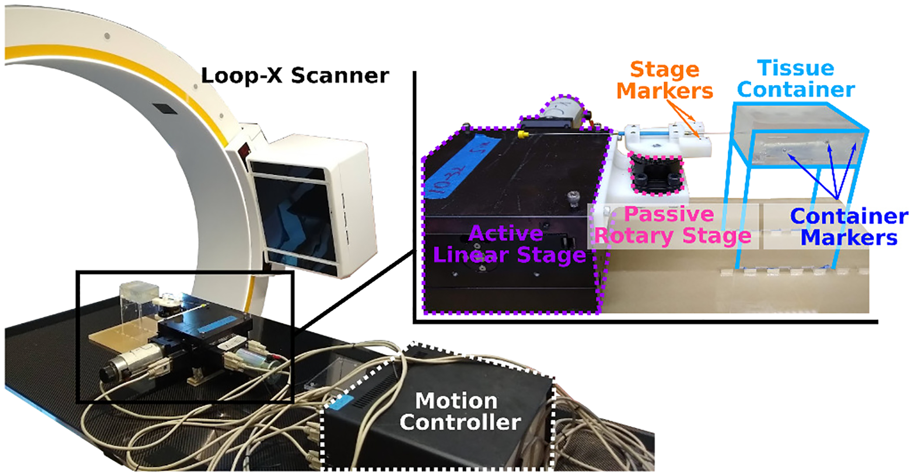
Experiment setup to study in situ needle bending. The active linear stage and passive rotary stage generate needle base motion. Markers on the stage and container are detectable in CT scans, and are used to calculate needle base motion from relative frame transformations.
As shown in Figure 3, the active linear stage will apply a lateral translation, and the passive rotary stage will rotate freely such that the needle will assume a least-energy configuration, forming a slope kb at the needle base. Since the point of needle base rotation is further away from the entry point than the control distance, the actual magnitude of db will be less than the amount of linear stage translation.
Fig. 3:

A top-down view of the needle base motion. When a lateral translation is applied, the inserted needle will bend and rotate freely about the passive rotary stage. The needle is allowed to freely translate in the axial direction so that the needle tip remains at the same insertion depth.
A stainless steel trocar needle of 1mm diameter is used in the experiment. Single layer of PVC tissue phantoms and porcine skeletal muscle samples are used as the surrounding medium. For the PVC phantoms, material models and parameters are obtained from compression tests, while the material properties for the porcine skeletal muscles are retrieved from literature, as described in Section II-B.
Three inserted depths of the needle l =20mm, 40mm and 60mm, as well as two control distances sb = 20mm and 40mm, are chosen as initial configurations. The linear stage translates laterally from −15mm to +15mm with 2.5mm increments. In sum, 156 data points are included in the experiment for the PVC tissue phantoms and porcine skeletal muscle samples.
Any metallic object will appear as an artifact in MRI images, therefore the needle shape cannot be determined precisely. In order to validate the proposed model, ground truth needle shapes will be extracted from CT images; motion parameters, db and kb, can also be obtained from successive CT scans.
D. Image Registration and Segmentation
Steel markers of two different sizes are embedded on the needle stage (stg) and the acrylic container (ctn), so as to differentiate between the moving stage frame Fstg and the fixed container frame Fctn. The needle and markers can be detected by the CT scanner (Loop-X, BrainLab, Munich, Germany) and segmented with intensity thresholding.
In order to extract needle base motion and other model parameters, a baseline scan is first taken to ensure the insertion is straight and perpendicular to the top surface of the medium. Control distance sb and inserted depth l, as well as the baseline stage frame Fstg0 is obtained from the baseline volume. The needle tip position is determined by the last detectable needle voxel after intensity thresholding. Subsequent volumes use the fixed container frame as global reference, and needle base motion, db and kb, can be extracted from relative frame changes between Fstgi and Fstg0.
An iterative closest point (ICP) method is used to register the markers detected in CT, FCT, with their positions by design, FDN. A brief explanation for finding relative needle base motions is offered in Algorithm 1.
A total of seven markers are placed on the moving stage, and twelve on the fixed container. Since only a few number of markers are used, and the components are fabricated with high accuracy, a one-to-one mapping between detected and designed marker positions is possible. A wrapper around the ICP algorithm performs random rotations to the point clouds until such mapping is established. In the rare cases where a marker moved outside of the volume, point rejection is performed to ensure equally accurate mapping on the remaining markers.
III. Results and Discussion
A. Mechanical Testing and Model Selection
The stretch-stress curves from compression tests are fitted with different hyperelastic models. For computational efficiency, two parameters are kept for curve fitting for models that have variable number of terms and parameters. As shown in Figure 4, candidate hyperelastic models: one-term Ogden, one-term Mooney-Rivlin, two-term Yeoh, and Neo-Hookean all fit the material well, with R2 > 99%; however, the Neo-Hookean model deviates from the other models when the compression ratio is higher than 0.8, therefore the Neo-Hookean model is rejected for inconsistency with the other models. The one-term Ogden model is selected for the PVC material, while the other two are equally valid choices.
Fig. 4:

Hyperelastic model fitting with selected number of specimens that showed consistent stretch-stress behaviors. All four models produce good fits, but the Neo-Hookean model deviates from the rest in compression higher than 0.8.
The one-term Ogden model with incompressibility constraint has form
| (7) |
where μ is the material shear modulus, and α is a model parameter that determines the overall shape of the stretch-stress curve. Constant J = det F, where F is the deformation gradient that is dependent on the choice of compression model, i.e. unconstrained (F = FU) or constrained (F = FC). For F = FC, the tissue is restricted from expanding along the x–direction, i.e. λ1 = 1.
| (8) |
| (9) |
Model parameters for this PVC phantom are μ = 12.72 kPa, and α = −1. Due to the nature of the compression test, the UEng model will be assigned to the PVC material.
Fresh pork loin are used as porcine skeletal muscle samples in ex vivo experiments. According to [31], model parameters for porcine skeletal muscles are μ = 3.63kPa and α = 8.74. For the porcine sample, both UTru and CTru compression models are used in the simulation.
B. Image Registration and Needle Reconstruction
The CT scanner uses an adaptive image acquisition method that produces variable slice spacing for different scans. The average slice spacing is approximately 0.5mm.
Using the centroids of detected markers volumes as their physical positions, the mean image registration error is 0.1mm for the stage markers, and 0.2mm for the container markers, due to slightly less accurate construction method of the acrylic container. The needle shape is reconstructed by a linear interpolation of the centroids of detected needle volume. Since the interpolation is performed voxel-wise, the interpolated shape truthfully represents the shape detected by the scanner, and no slope information is injected into the detected needle shape.
C. Simulation and Experiment Results
A custom FEM routine is written in MATLAB to solve the boundary value problem proposed in Equations 6. The needle is discretized into 1mm elements, and piecewise cubic Hermite interpolating polynomials and two-node isoparametric elements are used. Although only single-layer materials are used in the current experiment, the FEM routine is capable of simulating multilayer scenarios, as shown in Figure 5.
Fig. 5:

FEM simulation of in situ needle bending of an initially straight needle embedded in a multilayer medium with increasing stiffness. Lateral displacement of 15mm and slope of −40% are applied at the needle base. Slope at the needle base results in an RCM at x =17.5mm, while the needle COM is located at x =40.0mm.
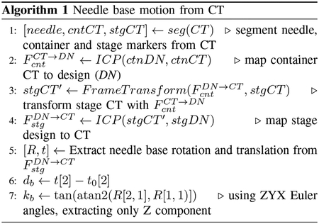
The stainless steel needle is assigned a Young’s Modulus of 200GPa [32]. Bent needle shapes detected by the CT scanner are compared against simulated shapes, provided the extracted needle base motions as well as material model parameters. Result of a typical trial is shown in Figure 6, with the reconstructed shapes overlaid with simulated shapes, as well as detected needle RCM, COM, and simulated COM as a result of needle motion.
Fig. 6:
Detected needle shape overlaid with simulated needle shape on a porcine sample by the UTru model. Point of insertion is at the origin. For a 60mm inserted depth and 40mm control distance, the least-energy needle RCM lands at approximately 23mm underneath the entry point, while the actual needle COM is at around 38mm. The simulated COM falls short at around 33mm.
A total of 156 CT scans are taken and analyzed. Table I lists the depths of needle RCM and COM with different combinations of inserted depths of the needle, materials and control distances.
Table I:
Detected and Simulated Needle RCM, COM [mm]
| M╲ l | 20 | 40 | 60 | 20 | 40 | 60 | |
|---|---|---|---|---|---|---|---|
| PVC | 9.7 | 10.9 | 9.0 | 8.4 | 6.8 | 2.6 | RCM |
| 10.3 | 24.3 | 31.1 | 10.9 | 23.9 | 37.5 | COM | |
| 11.3 | 21.3 | 25.9 | 11.4 | 21.0 | 25.5 | COMsim | |
| PSM | 12.6 | 21.0 | 26.2 | 11.9 | 20.6 | 22.6 | RCM |
| 13.4 | 25.7 | 39.5 | 10.6 | 25.7 | 38.5 | COM | |
| 12.7 | 23.8 | 35.0 | 11.8 | 23.1 | 33.8 | COMsim | |
| 20 | 40 | sb | |||||
Comparing by inserted depths l, when the l is small, the RCM and COM are located close to each other; but as l increases, so does the difference between the two centers. The depths of RCM and COM for porcine skeletal muscle sample (PSM, μ = 3.63kPa) increase steadily with increasing l, while the RCM for PVC (μ = 12.72kPa) becomes shallower when the control distance sb increases, indicating that the needle bends more outside of the tissue than the cases where the control distance is shorter.
In all cases, the natural RCM formed by the needle are not at the needle insertion point; their locations are instead dependent on the local relative stiffness of the needle and its surroundings. The needle COM has a more predictable and consistent behavior, at which point the net tissue displacement is zero, acting as an actual pivot point of the flexible needle.
D. Error Analysis
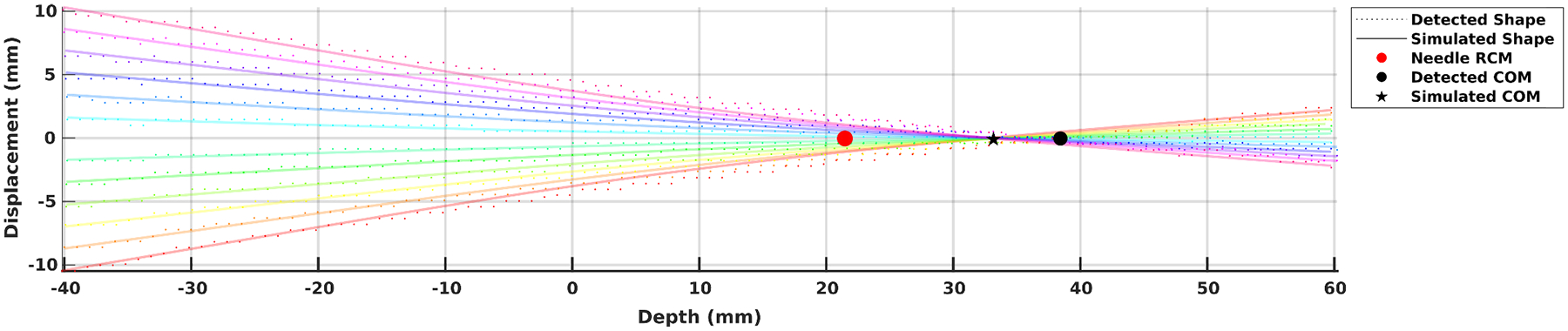
The needle tip prediction errors, calculated as the absolute distance between the detected and simulated needle tip, are shown as heatmaps in Figure 7. The effects of choice of compression models (UEng, UTru, CTru) and parameter values are explored. In terms of parameter values, subscript C indicates that the correct values are assigned to the corresponding material, while subscript I indicates that the incorrect values from the other material are used for the current material.
Fig. 7:

Median and maximum needle tip position simulation errors as compared with detected positions from CT. Unit in millimeters.
As shown in the figure, when proper material parameters and compression models are used, the errors on average can be kept at around 0.2mm for all inserted depths. In particular, prediction for porcine skeletal muscles with the UTru compression model has a maximum error of less than 0.5mm and median error less than 0.2mm, producing better overall tip position prediction than the other two models.
When taking the inserted depths l into account, it is evident from Figure 8 that at a shallow depth, the influence of compression models and material properties is limited, since the needle will bend less and the higher stiffness of the needle decides the overall behavior; however, this is not the case when the inserted depth is large, for which the effect of tissue compression is non-negligible. The UTru model for porcine skeletal muscle samples produces more consistent results overall, achieving a mean error of 0.15mm with variance 0.01mm2.
Fig. 8:
Simulation error distribution of porcine samples at different depths and with different compression models as well as parameter values. Unit in millimeters.
E. Clinical Relevance
The proposed needle-tissue interaction model helps establish the groundwork for needle shape prediction during in situ needle manipulations, and can be particularly useful in robot-assisted needle insertion procedures when a precise and safe tip adjustment is needed in order to realign the needle with its pre-planned trajectory. Through model simulation, the needle COM can be placed strategically to avoid excess tissue compression near critical anatomical structures.
The proposed method can be extended to other percutaneous needle interventions where precise needle placement is highly desirable, such as prostate brachytherapy, where the physician applies a force laterally to the needle shaft to adjust the needle tip position during an insertion [33].
Although patient-specific material model and parameters are difficult to obtain, results from biomechanical research can be transferred to the proposed application; using tissue-specific models and parameters can also lead to increase in simulation accuracy.
F. Limitations and Future Work
While the simulated needle tip positions agree with the experiment to a large extent, the simulated needle shape differs from the detected needle shape, as shown in Figure 6. The simulated needle shape is bounded from above and below by the detected needle shape, and the simulated needle COM is generally closer to the entry point than the detected COM. This discrepancy is in part due to imperfect experiment setup that permits sample motion, allowing the needle to bend less and translate more in the lateral direction. One way to complement the model is to use fiber Bragg grating (FBG) sensors along the needle such that known values of local curvature can be incorporated into the solution, thus achieving an overall better shape prediction.
Limitations of the proposed model include (1) an initially uncompressed tissue length t0 that must be assumed in order to model the amount of tissue compression, and (2) the needle must be initially straight and inserted perpendicular to the material surface. Both requirements might not be readily satisfied in an actual clinical setting. Future studies will examine ways to circumvent such requirements, either experimentally or from a model-based approach.
The simulation used material parameter values that are imperfect, which also contribute to the error in needle shape and tip prediction. However, without perfect knowledge of these parameter values, the model can still predict the overall needle shape and tip position to a great extent, thus relaxing the requirements for accuracy of the parameter values. More samples with different material properties, including multilayer samples, will be tested. Clinically available needles made from different materials, and with different diameters, will also be tested in the future to further evaluate the proposed model.
IV. Conclusion
An in situ needle manipulation technique used by physicians when performing spinal injections is modeled to study its effect on needle shape and needle tip position. An experiment setup is presented to verify the proposed model using both PVC phantoms and animal tissue samples. The UTru compression model is better suited for porcine skeletal muscles and can achieve less than 0.2mm tip prediction error. While the proposed method targets spinal injection procedures, it can be extended to other needle-based percutaneous procedures where accurate needle placement is highly desirable.
Interaction between flexible needle and soft tissue generates a needle RCM at the needle base, while a needle COM, which usually lies deeper underneath the insertion point, is where the needle actually pivots during needle rotation. The most natural needle RCM depends in large by the local relative stiffness of the needle and its surrounding medium, and should not be selected arbitrarily at the needle insertion point. The proposed model can help inform the best RCM location given a desired in situ needle tip adjustment.
Fig. 9:
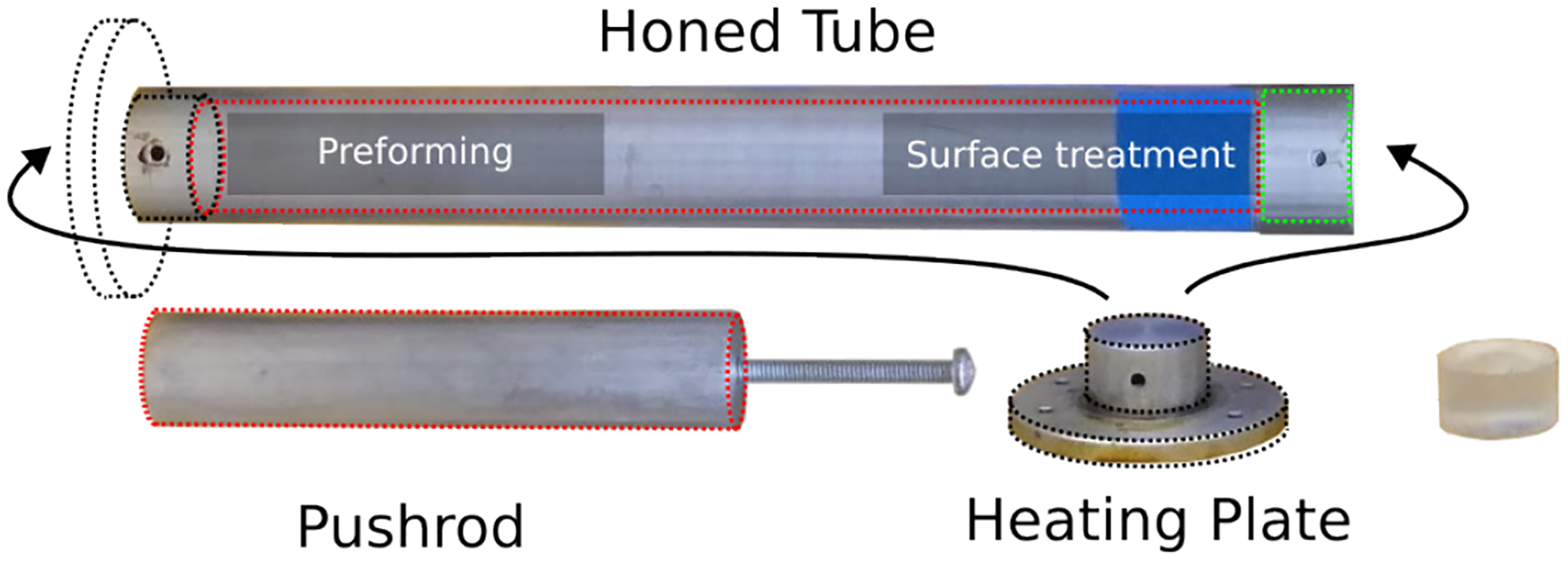
Equipment used to produce cylindrical test samples. A honed tube is used both for preforming the sample and also for treating the uneven cut surfaces. A heating plate transfers heat from a digital hotplate. A pushrod ensures contact between the uneven cut surface and the heating plate during surface treatment. Cylindrical specimens that are compliant to test standard can be fabricated with high repeatability.
Acknowledgments
This work was supported by NIH grants 1R01 EB025179-01 and 1R01 CA235134-01 and in part by a collaborative research agreement with the Multi-Scale Medical Robotics Center in Hong Kong.
Appendix A
Test Specimen Fabrication
Plastisols have been frequently used to make transparent, rubber-like tissue phantoms for modeling needle-based applications, but few have reported fabrication methods for test specimens for the purpose of obtaining their mechanical properties. Here, we present our method for fabricating cylindrical test specimens from liquid plastisols with high repeatability, and the test specimen fabricated can be compliant to compression testing standards.
A major difficulty for fabricating cylindrical test specimens is to create surfaces that are smooth. Due to high flexibility of these materials, cutting them with a blade does not produce a flat surface, as they will deform as soon as there is pressure applied. Here, we use the fact that cured plastisols melt under high temperature in order to treat the uneven cut surfaces.
In terms of equipment, a honed tube with 1–1/8in inner diameter (ID) with two slightly enlarged ends is used to form the cylindrical shape of the specimen. A heating plate can be securely attached to either side of the tube, and is used to transfer heat from a digital hotplate. The ID for surface treatment (green) is slightly larger than that of the preforming side of the tube, allowing easier attachment of the tube with the heating plate. A pushrod is used to ensure contact between the preformed specimen with the heating plate during the surface treatment process. Temperature and time listed are specific to the plastisol composition used in this study.
Pre-heat the digital hotplate to 325°C.
Measure 50ml liquid plastisol.
Attach the heating plate to the preforming side of the tube.
Pour the measured plastisol in the tube and heat for 30mins; shake the tube at 15min time stamp.
Transfer tube into a liquid bath that submerges the bottom section of the tube, and let it cool for 15 mins.
Take the tube out of the bath, and remove the heating plate by pulling straight. The preformed sample should be attached to the inner wall of the tube, and detached from the heating plate.
Peel the sample off of the inner wall of the tube and remove from the tube.
Cut the sample to a desired length with a blade.
Reheat only the bottom plate to 300°C, and transfer it onto a workbench.
Re-insert the sample to the surface treatment side of the tube, with the uneven surface facing the heating plate.
Re-attach the tube to the heating plate, and use the pushrod to generate pressure on the sample to ensure contact between the uneven surface and the heating plate. Wait for 2mins.
Transfer the assembly to the liquid bath, and submerge the bottom section for 10mins.
Remove the assembly from the liquid bath, and remove the heating plate.
Peel the finished sample off of the inner wall of the tube. Process complete.
Footnotes
This paper was recommended for publication by Editor Jessica Burgner-Kahrs upon evaluation of the Associate Editor and Reviewers’ comments.
References
- [1].Silbergleit R, Mehta BA, Sanders WP, and Talati SJ, “Imaging-guided injection techniques with fluoroscopy and ct for spinal pain management,” Radiographics, vol. 21, no. 4, pp. 927–939, 2001. [DOI] [PubMed] [Google Scholar]
- [2].Giordano BD, Baumhauer JF, Morgan TL, and Rechtine GR, “Cervical spine imaging using standard c-arm fluoroscopy: patient and surgeon exposure to ionizing radiation,” Spine, vol. 33, no. 18, pp. 1970–1976, 2008. [DOI] [PubMed] [Google Scholar]
- [3].Lee K, Lee KM, Park MS, Lee B, Kwon DG, and Chung CY, “Measurements of surgeons’ exposure to ionizing radiation dose during intraoperative use of c-arm fluoroscopy,” Spine, vol. 37, no. 14, pp. 1240–1244, 2012. [DOI] [PubMed] [Google Scholar]
- [4].Halpern S and Preston R, “Postdural puncture headache and spinal needle design: metaanalyses,” The Journal of the American Society of Anesthesiologists, vol. 81, no. 6, pp. 1376–1383, 1994. [DOI] [PubMed] [Google Scholar]
- [5].Bogduk N, Dreyfuss P, Baker R, Yin W, Landers M, Hammer M, and Aprill C, “Complications of spinal diagnostic and treatment procedures,” Pain Medicine, vol. 9, no. suppl 1, pp. S11–S34, 2008. [Google Scholar]
- [6].Su H, Kwok K-W, Cleary K, Iordachita I, Cavusoglu MC, Desai JP, and Fischer GS, “State of the art and future opportunities in mri-guided robot-assisted surgery and interventions,” Proceedings of the IEEE, vol. 110, no. 7, pp. 968–992, 2022. [DOI] [PMC free article] [PubMed] [Google Scholar]
- [7].Susil RC, Krieger A, Derbyshire JA, Tanacs A, Whitcomb LL, Fichtinger G, and Atalar E, “System for mr image–guided prostate interventions: canine study,” Radiology, vol. 228, no. 3, pp. 886–894, 2003. [DOI] [PMC free article] [PubMed] [Google Scholar]
- [8].Susil RC, Camphausen K, Choyke P, McVeigh ER, Gustafson GS, Ning H, Miller RW, Atalar E, Coleman CN, and Ménard C, “System for prostate brachytherapy and biopsy in a standard 1.5 t mri scanner,” Magnetic Resonance in Medicine: An Official Journal of the International Society for Magnetic Resonance in Medicine, vol. 52, no. 3, pp. 683–687, 2004. [DOI] [PMC free article] [PubMed] [Google Scholar]
- [9].Krieger A, Susil RC, Ménard C, Coleman JA, Fichtinger G, Atalar E, and Whitcomb LL, “Design of a novel mri compatible manipulator for image guided prostate interventions,” IEEE Transactions on Biomedical Engineering, vol. 52, no. 2, pp. 306–313, 2005. [DOI] [PMC free article] [PubMed] [Google Scholar]
- [10].Su H, Shang W, Cole G, Li G, Harrington K, Camilo A, Tokuda J, Tempany CM, Hata N, and Fischer GS, “Piezoelectrically actuated robotic system for mri-guided prostate percutaneous therapy,” IEEE/ASME transactions on mechatronics, vol. 20, no. 4, pp. 1920–1932, 2014. [DOI] [PMC free article] [PubMed] [Google Scholar]
- [11].Chen Y, Xu S, Squires A, Seifabadi R, Turkbey IB, Pinto PA, Choyke P, Wood B, and Tse ZTH, “Mri-guided robotically assisted focal laser ablation of the prostate using canine cadavers,” IEEE Transactions on Biomedical Engineering, vol. 65, no. 7, pp. 1434–1442, 2017. [DOI] [PMC free article] [PubMed] [Google Scholar]
- [12].Li G, Su H, Cole GA, Shang W, Harrington K, Camilo A, Pilitsis JG, and Fischer GS, “Robotic system for mri-guided stereotactic neurosurgery,” IEEE transactions on biomedical engineering, vol. 62, no. 4, pp. 1077–1088, 2014. [DOI] [PMC free article] [PubMed] [Google Scholar]
- [13].Guo Z, Dong Z, Lee K-H, Cheung CL, Fu H-C, Ho JD, He H, Poon W-S, Chan DT-M, and Kwok K-W, “Compact design of a hydraulic driving robot for intraoperative mri-guided bilateral stereotactic neurosurgery,” IEEE Robotics and Automation Letters, vol. 3, no. 3, pp. 2515–2522, 2018. [Google Scholar]
- [14].Xiao X, Gao H, Li C, Qiu L, Kumar KS, Cai CJ, Bhola BS, King NKK, and Ren H, “Portable body-attached positioning mechanism toward robotic needle intervention,” IEEE/ASME Transactions on Mechatronics, vol. 25, no. 2, pp. 1105–1116, 2020. [Google Scholar]
- [15].Monfaredi R, Seifabadi R, Iordachita I, Sze R, Safdar NM, Sharma K, Fricke S, Krieger A, and Cleary K, “A prototype body-mounted mri-compatible robot for needle guidance in shoulder arthrography,” in 5th IEEE RAS/EMBS International Conference on Biomedical Robotics and Biomechatronics, pp. 40–45, IEEE, 2014. [DOI] [PMC free article] [PubMed] [Google Scholar]
- [16].Li G, Patel NA, Liu W, Wu D, Sharma K, Cleary K, Fritz J, and Iordachita I, “A fully actuated body-mounted robotic assistant for mri-guided low back pain injection,” in 2020 IEEE International Conference on Robotics and Automation (ICRA), pp. 5495–5501, IEEE, 2020. [DOI] [PMC free article] [PubMed] [Google Scholar]
- [17].Cheung C-L, Ho JD-L, Vardhanabhuti V, Chang H-C, and Kwok K-W, “Design and fabrication of wireless multilayer tracking marker for intraoperative mri-guided interventions,” IEEE/ASME Transactions on Mechatronics, vol. 25, no. 2, pp. 1016–1025, 2020. [Google Scholar]
- [18].Kuo C-H and Dai JS, “Robotics for minimally invasive surgery: a historical review from the perspective of kinematics,” in International symposium on history of machines and mechanisms, pp. 337–354, Springer, 2009. [Google Scholar]
- [19].Stoianovici D, Jun C, Lim S, Li P, Petrisor D, Fricke S, Sharma K, and Cleary K, “Multi-imager compatible, mr safe, remote center of motion needle-guide robot,” IEEE Transactions on Biomedical Engineering, vol. 65, no. 1, pp. 165–177, 2017. [DOI] [PMC free article] [PubMed] [Google Scholar]
- [20].Bassan HS, Patel RV, and Moallem M, “A novel manipulator for percutaneous needle insertion: Design and experimentation,” IEEE/ASME transactions on mechatronics, vol. 14, no. 6, pp. 746–761, 2009. [Google Scholar]
- [21].Zhang N, Huang P, and Li Q, “Modeling, design and experiment of a remote-center-of-motion parallel manipulator for needle insertion,” Robotics and Computer-Integrated Manufacturing, vol. 50, pp. 193–202, 2018. [Google Scholar]
- [22].Wang Y, Li G, Kwok K-W, Cleary K, Taylor RH, and Iordachita I, “Towards safe in situ needle manipulation for robot assisted lumbar injection in interventional mri,” in 2021 IEEE/RSJ International Conference on Intelligent Robots and Systems (IROS), pp. 1835–1842, IEEE, 2021. [DOI] [PMC free article] [PubMed] [Google Scholar]
- [23].Fritz J, U-Thainual P, Ungi T, Flammang AJ, Cho NB, Fichtinger G, Iordachita II, and Carrino JA, “Augmented reality visualization with image overlay for mri-guided intervention: accuracy for lumbar spinal procedures with a 1.5-t mri system,” American Journal of Roentgenology, vol. 198, no. 3, pp. W266–W273, 2012. [DOI] [PubMed] [Google Scholar]
- [24].Li G, Patel NA, Wang Y, Dumoulin C, Loew W, Loparo O, Schneider K, Sharma K, Cleary K, Fritz J, et al. , “Fully actuated body-mounted robotic system for mri-guided lower back pain injections: Initial phantom and cadaver studies,” IEEE robotics and automation letters, vol. 5, no. 4, pp. 5245–5251, 2020. [DOI] [PMC free article] [PubMed] [Google Scholar]
- [25].Simon P, Orías AAE, Andersson GB, An HS, and Inoue N, “In vivo topographic analysis of lumbar facet joint space width distribution in healthy and symptomatic subjects,” Spine, vol. 37, no. 12, p. 1058, 2012. [DOI] [PMC free article] [PubMed] [Google Scholar]
- [26].Glozman D and Shoham M, “Image-guided robotic flexible needle steering,” IEEE Transactions on Robotics, vol. 23, no. 3, pp. 459–467, 2007. [Google Scholar]
- [27].Humphrey JD and Delange SL, “An introduction to biomechanics,” Solids and Fluids, Analysis and Design. Springer, Heidelberg, 2004. [Google Scholar]
- [28].Martins PALS, Natal Jorge RM, and Ferreira AJM, “A comparative study of several material models for prediction of hyperelastic properties: Application to silicone-rubber and soft tissues,” Strain, vol. 42, no. 3, pp. 135–147, 2006. [Google Scholar]
- [29].Singh G and Chanda A, “Mechanical properties of whole-body soft human tissues: a review,” Biomedical Materials, 2021. [DOI] [PubMed] [Google Scholar]
- [30].ASTM D575–91(2018), “Standard test methods for rubber properties in compression,” standard, ASTM International, PA, USA, Aug. 2018. [Google Scholar]
- [31].Mo F, Zheng Z, Zhang H, Li G, Yang Z, and Sun D, “In vitro compressive properties of skeletal muscles and inverse finite element analysis: Comparison of human versus animals,” Journal of Biomechanics, vol. 109, p. 109916, 2020. [DOI] [PubMed] [Google Scholar]
- [32].Adagolodjo Y, Goffin L, De Mathelin M, and Courtecuisse H, “Robotic insertion of flexible needle in deformable structures using inverse finite-element simulation,” IEEE Transactions on Robotics, vol. 35, no. 3, pp. 697–708, 2019. [Google Scholar]
- [33].Jamaluddin MF, Ghosh S, Waine MP, Tavakoli M, Amanie J, Murtha AD, Yee D, and Usmani N, “Intraoperative factors associated with stranded source placement accuracy in low-dose-rate prostate brachytherapy,” Brachytherapy, vol. 16, no. 3, pp. 497–502, 2017. [DOI] [PubMed] [Google Scholar]