

Abstract
Face gear transmission is a kind of space-meshing mechanism that is mainly used in the field of aviation. Compared with traditional transmission, it has the advantages of stability, reliability, low noise, and strong carrying capacity. However, owing to its complex tooth surface, there are no means to accurately model the face gear. Likewise, research based on the geometry is difficult. Therefore, the tooth surface equation of the face gear is derived in this article based on the meshing theory. Based on the equations, the point cloud of the face gear tooth surface is calculated, the complex tooth surface is generated, and the face gear is accurately modeled. Moreover, taking tooth surface friction excitation into consideration, a multi-degree-of-freedom nonlinear dynamic model of face gear transmission system is established, using the adaptive variable step length Runge–Kutta method. As shown in the results, the bifurcation diagram, phase diagram, time history diagram, and Poincaré section diagram are combined to analyze the influence of tooth surface friction and meshing frequency on the dynamic characteristics of the system.
Keywords: Face gear, precise modeling, nonlinear dynamics, friction
Introduction
The face gear is a widely researched new transmission mechanism. This mechanism can be widely used in the special transmission area, especially in the field of aviation. Since the contour of the face gear is complex, it cannot be modeled directly. The most common method of mechanical transmission is that of gear transmission, in which the tooth surfaces contact each other to transmit power, although the friction mechanism between the driving gear and the driven gear remains complicated. The friction between the teeth has a direct impact on the vibration and noise in the transmission process. Therefore, it is important to research on the accurate modeling of the three-dimensional (3D) model of the face gear and to study the nonlinear dynamics of the tooth surface friction excitation on the gear transmission system.
At present, research on face gears and in the related fields is ongoing. Some works mainly deal with the tooth surface modeling and processing technology. He and Lin 1 derived the tooth meshing equation of gears according to the meshing theory, established the model of the spiral pinion, and studied the contact characteristics of the gear pair by experiments. Based on the meshing theory, Saribay et al. 2 proposed a method to create a tooth surface by a conjugate former, which meshes with the face gear. Tsay and Fong 3 proposed an improved face gear profile modification method, which improved the controllability of the face gear pair contact mode and improved the transmission characteristics. Liu et al. 4 designed a new type of face gear that can mesh with space eccentric gears and simulate the meshing state using finite element analysis; it provides a reliable basis for the strength design of the new gear. Liu et al. 5 proposed a new configuration of the face gear, the endface of which is wavy, the pinion gear meshed with it is a noncircular gear, and the tooth surface point calculation program of this special face gear is enhanced. Lin et al. 6 studied the design method of the orthogonal wave face gear, built its 3D model in 3D software, and analyzed its motion law. Zanzi and Pedrero 7 developed a method for manufacturing double crown gears in order to reduce the influence on the installation error during the face gear transmission. Mo and Zhang 8 completed the 3D solid modeling of spiral bevel gears by numerical method and carried out the gear contact experiment. This provides a reference for studying the meshing behavior of gears. Litvin et al. 9 proposed a new method of machining a face gear using a particular shape of worm that can be used to produce a grinding worm with no singular surface, and a face gear by a rootless and nonfixed forming method. Tang et al. 10 based on the shortcomings of the current face gear processing method, improved the method from the tool and adopted the progressive grinding method. This provides a reference for the precision machining research of face gears. Tang and Yang 11 developed a planing method for machining face gears using a four-axis computer numeric control (CNC planer). Wang et al. 12 proposed a mathematical model for surface roughness of surface gear grinding based on the principle of surface gear grinding. The influence of the grinding parameters on the tooth surface roughness was analyzed through experiments. On this basis, the grinding method was improved. Wang et al. 13 proposed the face gear honing processing technology and carried out the surface quality inspection of the machined face gear based on the traditional grinding process. This has promoted the development of precision machining technology for face gears. Wang et al. 14 studied the grinding of face gears using cubic boron nitride (CBN) grinding wheels. Dudás and Bodzás 15 studied the geometric design method of the hob used in the face gear machining, and established its 3D solid model, which was simulated in software. Guo et al. 16 proposed a grinding method for face gears with CNC machines. The study provides an effective approach for parameter selection of highly precise and efficient grinding of face gears.
Some scholars have studied the meshing contact characteristics and dynamic characteristics of gears. Litvin et al. 17 developed a numerical analysis method for analyzing the contact stress of the face gear and pinion. Guingand et al. 18 analyzed the load problem of the face gear in transient contact. Saribay 19 studied the root bending stress of the face gear and compared it with the bending stress of the ordinary cylindrical gear. It has a certain guiding significance for the contact stress of the research surface gear. Li and Zhu 20 proposed the calculation formula of the meshing impact force of the face gear pair, and studied the relationship between the meshing impulse and the static transmission error. Based on this, a four-degree-of-freedom dynamic model is constructed, and the influence of the meshing impact on the dynamic characteristics of the gear pair is analyzed. Barone et al. 21 established the three-tooth meshing model of the face gear pair, and used the numerical analysis method and the finite element method (FEM) to study the contact characteristics of the two gears under load. Chen et al. 22 established a dynamic model including time-varying stiffness, backlash, and other factors, and studied its influence on the nonlinear dynamics by numerical methods. Li et al. 23 developed a micro-punch web for reducing noise during the face gear transmission process and constructed its mathematical model and the experimental results were used to verify the actual effect of micro-punch webs. Kawasaki et al. 24 reduced the influence of the mounting error on the face gear by defining the reference point of the gear, and studied the influence of the helix angle on the position of the mesh line. Bodzás and Dudás 25 studied the tooth surface generation method of the spiroid face gear and designed its machining tool. The correctness of calculation is verified by actual machining. Fu et al. 26 constructed a six-degree-of-freedom dynamic model of the planetary roller screw mechanism with friction excitation, and explored the change in the motion state of the system under different load conditions. Concli et al. 27 developed a planar torsional lumped parameter model for simulating the dynamic and vibrational behavior of planetary gear trains. The correctness of calculation was confirmed by FEM. This study provides a reference for calculating the kinetic parameters of complex models.
At present, most researches focus on the processing technology of face gears, their meshing contact characteristics, and so on. However, there are few studies on the precision modeling technology and the influence of friction excitation on the dynamics of the face gear transmission system. Accurate modeling of the face gear is the basis of subsequent research. In order to further promote the development of face gears, it is urgent to accurately model the complex tooth surface of the face gear and the nonlinear dynamics of the friction gear. Therefore, based on the meshing theory, this article derives the tooth surface equation of the face gear, calculates the point cloud of the face gear tooth surface, generates the complex tooth surface of the face gear, and completes the 3D solid modeling of complex tooth profiles of face gears. On this basis, the nonlinear dynamic model of multi-degree-of-freedom face gear transmission system considering tooth surface friction excitation is established, and the influence of nonlinear dynamic phenomena of tooth surface friction on the gear transmission system is studied. This study lays a solid foundation for subsequent research on the meshing behavior and transmission characteristics of the face gear.
Precise modeling of complex tooth surface of face gear
Coordinate system in face gear machining
It is necessary to establish four coordinate systems in the process of calculating the face gear tooth surface. Two of them are ss = (os, xs, ys, zs) and s2 = (o2, x2, y2, z2), which are rigidly connected to the tool and the face gear, where zs and z2 are, respectively, aligned with the axes of the tool and the face gear, and the angle γ between them is the drive axis angle. The other two fixed coordinate systems are ss0 = (os0, xs0, ys0, zs0) and s20 = (o20, x20, y20, z20). The angle φs between xs0 and xs indicates the tool rotation angle, while the angle φ2 between x20 and x2 denotes the face gear rotation angle. Figure 1 shows the relationship between the various coordinate systems, from which the transformation matrix between the coordinate systems is obtained in equations (1)–(5) as follows
Figure 1.

Coordinate system for face gear machining.
| (1) |
| (2) |
| (3) |
| (4) |
| (5) |
In the above equations, [M20, s0] represents a transition from the coordinate system Ss0 to the coordinate system S20, while [Ms0, s] represents a transition from the coordinate system Ss to the coordinate system Ss0. [M20, 2] is a conversion matrix between the coordinate system S2 and the coordinate system S20. After derivation, the two conversion relationships [M2, s0] and [M2, s] can be obtained, respectively.
Tooth surface equation of the tool
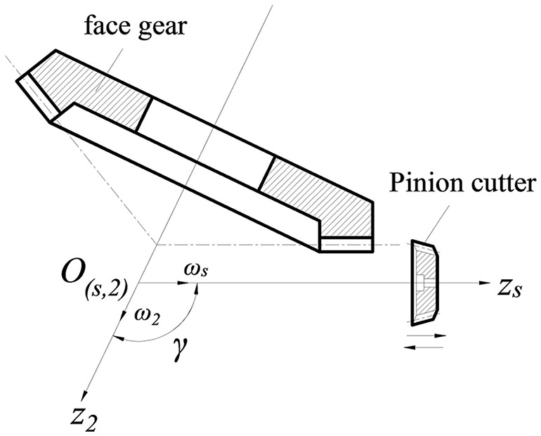
The tooth surface of the face gear is formed based on the forming process of the spur gear cutter and the face gear, as shown in Figure 2. The tool axis and the face gear axis are, respectively, zs and z2, and the axis angle between the face gear and the pinion cutter is γ. Both the face gear and the pinion cutter rotate around their own axis.
Figure 2.
Face gear machining diagram.
The coordinate system used for the involute tool tooth surface corresponds to the coordinate system in Figure 1, and its cross section is an involute tooth type. The specific shape and parameters are shown in Figure 3.
Figure 3.

Schematic diagram of the involute tool.
From Figure 3, the tool tooth surface equation can be derived, where ξs, θs is used to indicate the tool involute tooth surface vector equation rs as
| (6) |
where ξs is the axial parameter of a point on the tooth surface of the tool and determines the tooth width of the tooth surface of the tool; θs is the angle parameter of the point on the involute curve of the tool and determines the height of the tooth surface of the tool; rbs is the base circle radius of the tool involute; and θs0 is the angle parameter of the tool slot symmetry line to the starting point of the involute, where the sign corresponds to the involute on both sides of the tool slot. θs0 is determined as
| (7) |
where Ns is the number of teeth of the tool, αs is the tool pressure angle, and invαs is the involute function of the pressure angle αs.
Then the unit normal vector of tool tooth surface is
| (8) |
In the transmission process, the transition face of the tool pinion does not participate in the engaging process. Therefore, a relatively simple method can be used to determine the transition part of the pinion by drawing a tangent semicircle between the base circle and the index circle in the 3D software.
Meshing equation of face gear
The process of machining the face gear can be regarded as the meshing process of the two gears in the simulation space. Thus, when solving the meshing equation of the surface gear tooth surface, the relative speed of the contact point between the pinion tool and the face gear tooth surface is first determined.
Suppose the point M is a contact point between the tool and the face gear face, and the vector rs in the tool coordinate system is
| (9) |
In equation (9), if , , are the unit vectors in the Ss coordinate system, and the rotational speed of the tool is , then the velocity of the M point in the tool coordinate system is
| (10) |
The point M in the tool coordinate system can be converted to another point in the face gear coordinate system, the conversion relationship of which is shown as
| (11) |
Also, the rotational angular velocity of the face gear at point M can be derived as
| (12) |
The speed vector of the tool relative to the face gear can be obtained as
| (13) |
Assuming that the number of teeth of the tool and the face gear are Ns and N2, respectively, and the gear ratio is qs2 and q2s, then
| (14) |
According to the meshing theory, the relative movement speed of the tooth surface at the contact point is perpendicular to the direction of the common normal vector, that is, the two tooth surfaces have no relative motion along the common normal direction of the contact point, and
| (15) |
where is the unit normal vector on the tooth surface of the tool and is the relative motion speed of the tooth surface contact point converted into the coordinate system Ss. These two variables are solved in equation (15). Therefore, the meshing equation of the tool and the surface gear can be obtained as
| (16) |
where .
Tooth surface equation of face gear
The tooth surface equation of the tool is converted from the coordinate system Ss to S2, and the relationship between the two coordinate systems is expressed as in equation (5). The equation of the face of the tooth surface of the tool in the coordinate system S2 can be derived as
| (17) |
Calculated in conjunction with equation (16), the tooth surface equation of the face gear working surface can be obtained as
| (18) |
where , is the ratio of the number of teeth of the tool to the number of teeth of the face gear.
The tooth surface of the face gear includes a working tooth surface and a root transition tooth surface. The tooth root transition surface is a trajectory curved surface formed by the enveloping of the tooth tip of the pinion cutter and the root portion of the machined face gear during the machining process of the face gear. Replacing the tool tooth surface parameter θs with
| (19) |
In the coordinate system S2, the equation for the transition surface is
| (20) |
After derivation, the component form of the transition surface equation is obtained as
| (21) |
where .
Parametric modeling
Due to the particularity of the profile of the face gear tooth surface, a discrete point method is used to generate the tooth surface. According to the matrix equation of the face gear tooth surface and its parameters, Matlab is used to solve the problem, and a series of coordinate points of the face gear working face and the transition surface and the face gear meshing with the pinion tooth surface are calculated, respectively. The specific parameters used in the calculation are tool modulus 5 mm, tooth number 20, pressure angle 20°, tooth top height coefficient ha* = 1, head clearance coefficient c* = 0.25, and face gear tooth number 60.
According to the calculated tooth surface discrete point cloud, the tooth surface simulation is carried out in Matlab, and the tooth surface simulation of the face gear working face and the transition surface and the pinion working face is obtained. The calculated point coordinates are edited to generate discrete point cloud files for importing into the 3D modeling software (SolidWorks). Thus, a complex surface is generated in the software, and then a spatial 3D model of a single tooth is drawn. A complete 3D solid model is obtained by arraying the individual teeth. Finally, the generated face gear and the pinion gear are assembled to obtain a meshing state model of the two gears as shown in Figures 4–13.
Figure 4.

Point cloud file of gear’s working face.
Figure 5.

Point cloud file of transition surface.
Figure 6.

Working face of face gear.
Figure 7.

Transition surface of face gear.
Figure 8.

Single tooth model of gear.
Figure 9.

Solid model of gear.
Figure 10.

Point cloud file of pinion.
Figure 11.

Tooth surface of pinion.
Figure 12.

Single tooth model of pinion.
Figure 13.

Solid model of pinion.
A series of points of the tooth surface are obtained by Matlab calculation, and a discrete point cloud file format that can be imported into the 3D modeling software (SolidWorks) is generated after editing. As shown in Figures 4 and 5, they are the discrete point cloud files of the face gear and the transition surfaces. Figures 6–8 show that these tooth surface discrete points are simulated in Matlab, and the tooth surface simulation of the face gear can be obtained. The point cloud file is imported into SolidWorks, and the generated complex surface is processed to obtain a 3D model of a single tooth. Figure 9 is a complete 3D model of the face gear after arraying. Figures 10–13 show the generating process of the pinion gear, and the generating steps are similar to the generating steps of the face gear. Figures 14 and 15 show the two gear meshing state models assembled by the generated face gear and pinion gear.
Figure 14.

Assembly drawing of face gear.
Figure 15.

Partial meshing diagram.
Nonlinear dynamics of face gear transmission system
Nonlinear dynamic model of face gear transmission system
The face gear transmission is a new type of transmission mode where a face gear engages with a spur gear. According to Newton’s second law, the dynamic model of the face gear transmission system is established by the lumped parameter method. Figure 16 shows the nonlinear dynamic model of face gear transmission system.
Figure 16.

Nonlinear dynamic model of face gear transmission system.
In the dynamic model, the two gears are considered as lumped mass inertia blocks and are located in the middle of their respective supports. The support shaft is considered as a massless rigid body, the bearing is elastic support, and the spring and damping are used for simulation. In the transmission process, there are radial and circumferential components on the spur gear, axial and circumferential components on the face gear, and no axial and radial forces. The entire system considers seven degrees of freedom, which are
| (22) |
where x1 and z1 are the translational degrees of freedom of the spur gear in the x and z directions, θy1 is the rotation of the spur gear in the Y-axis direction, and x2 and z2 are the translational degrees of freedom of the face gear in the x and z directions, respectively. θz2 is the rotational freedom of the face gear and θx2 is the torsion of the face gear in the X-axis direction.
Tooth surface friction analysis
According to the meshing characteristics of the gear transmission system, the face gear and the spur gear are in point contact. In the process of transmission, there is rolling in node P of the spur gear and there is no sliding friction. In addition to the other positions outside the node, the two movements exist at the same time, and there is sliding friction. The direction of the friction is always perpendicular to the meshing line. As shown in Figure 17, the friction at node P and the relative velocity are 0. After passing through the point P, the relative velocity direction changes, and the frictional force periodically changes.
Figure 17.

Friction direction diagram.
According to Coulomb’s friction law, the amount of friction is proportional to the positive pressure, and the friction at the engaging point is
| (23) |
where μ is the friction coefficient, Fn is the positive pressure of the tooth surface, and sign(G) is a sign function, expressed as
| (24) |
Nonlinear differential equation of face gear transmission system
Due to the existence of factors such as vibration error, a relative displacement λn is generated in the normal direction of the meshing portion in the face gear transmission system, which is expressed as
| (25) |
where r1 and r2 are the meshing point radii of the spur gear and the face gear, respectively, α is the normal pressure angle, and en(t) is the transmission error in the normal direction of the face gear pair.
In the process of gear manufacturing and installation, error is unavoidable. These error excitations have great influence on the gear meshing transmission. The teeth collide with each other, which is the main factor that produces noise and vibration. In order to facilitate the study, the transfer error is fitted by a simple harmonic function, which is expressed as
| (26) |
where e(t) is a function of the gear pair transmission error as a function of time t, e0 is the error constant, er is the amplitude, usually e0 = 0, ωn is the meshing angle frequency, and Φ is the phase angle, generally taken as Φ = 0.
The meshing force between the face gear and the spur gear and the component force in each direction are expressed as
| (27) |
where km is the average meshing stiffness, cm is the vibration model meshing damping, and f(λn) is the gap function, which can be defined as
| (28) |
Stiffness excitation is an important parameter in the calculation of dynamic equations. The tooth surface of the face gear is quite complicated, and the tooth thickness along the length of the tooth is variable. For the point contact in face gear transmission, the analytical solution of the comprehensive meshing stiffness of the tooth is difficult to calculate. Therefore, this article uses the FEM to calculate the stiffness of the face gear. The finite element model of the face gear was constructed in the preprocessing software. As shown in Figure 18, a three-tooth model was used for the convenience of calculation. Then the calculation is performed in the finite element software to obtain the meshing rigidity of the teeth. The stiffness curve is shown in Figure 19. The average meshing stiffness is km = 3.13 × 10⁸ N/m.
Figure 18.

Three-tooth finite element model.
Figure 19.
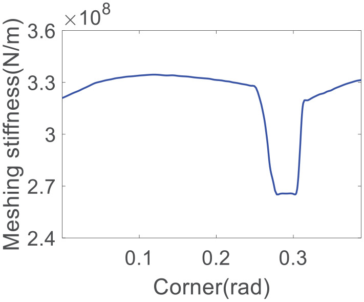
Meshing stiffness curve.
The differential equations of motion are listed for each vibration direction of the opposite gear transmission system based on Newton’s second law. The vibration equations of the transmission system can be obtained as follows
| (29) |
where m1, m2, J1y, and J2z are the concentrated mass and moment of inertia of the spur gear and the face gear, respectively, and J2x is the moment of inertia of the face gear on the X-axis. cij and kij (i = 1, 2, j = x, z) are the damping and support stiffness of the face gear pair in the X-axis and Z-axis directions, respectively. T1 is the input torque, acting on the spur gear, and T2 is the load torque acting on the face gear, while kθx2 and cθx2 are the torsional stiffness and damping of the face gear in the X-axis direction, respectively. Fx is the component of the dynamic meshing force in the X-axis direction, Fz is the component force in the Z-axis direction, and sign(G) is the sign function of the time-varying frictional force.
Equation (29) is a set of strong nonlinear second-order differential equations with multi-degree of freedom, variable parameters, tooth side clearance, and time-varying friction of the face gear transmission system. In order to facilitate the solution, the equation needs to be appropriately transformed. To eliminate the rigid body displacement of the system, the displacement λn in the direction of the mesh line is introduced as a new degree of freedom. The torsional vibrations in the nonlinear equation of the orthogonal face gear transmission system are combined to obtain the following formula
| (30) |
where , , me is the equivalent mass of the gear pair , the load on the gear , load average , load variation and is the first-order harmonic amplitude of the external load. is the external excitation fundamental frequency and is the phase angle of the external load.
For the gear system, the magnitude of each physical quantity in the dynamic differential equation often varies greatly. For example, the magnitude of the meshing stiffness is between 107 and 109, and the magnitude of the damping coefficient is between 102 and 104. Therefore, for the convenience of solving, the nonlinear normalized equations are dimensionless normalized.
Introducing the gear sub-half clearance b0 as the displacement nominal scale, the above-mentioned dynamics equations are dimensioned and processed as
| (31) |
where
Response of tooth surface friction coefficient to system cycle and chaos
The fourth-order variable step size adaptive Runge–Kutta numerical integration method is used to solve the differential equations of the face gear transmission system. The main parameters are shown in Table 1. The bifurcation characteristics of the relative displacement of the system with the friction coefficient are obtained as shown in Figure 20.
Table 1.
Main parameter list.
| The main parameters | Numerical value |
|---|---|
| Number of teeth of spur gear N1 | 36 |
| Number of face gears N2 | 123 |
| Modulus m/mm | 4 |
| Pressure angle α/(°) | 20 |
| Cylindrical gear quality m1/kg | 2.3 |
| Face gear quality m2/kg | 33.5 |
| Tooth width b/mm | 24 |
| Input torque T1/(N·m) | 300 |
| Flank clearance bc/μm | 100 |
| Average meshing stiffness km/(N·m−1) | 3.13 × 10⁸ |
| Average meshing damping cm/(N·s·m−1) | 0.5 × 10⁴ |
Figure 20.
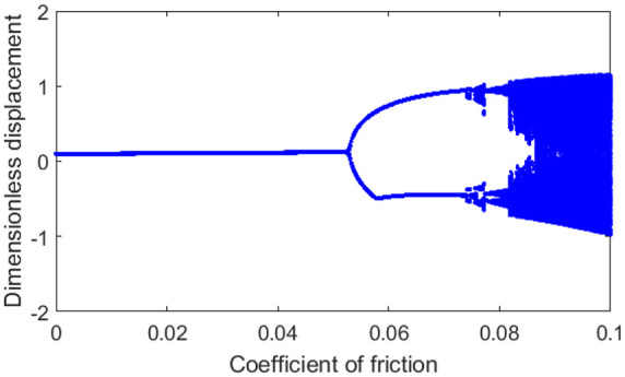
System bifurcation diagram when friction coefficient changes.
According to the bifurcation diagram, the system exhibits a rich nonlinear dynamic phenomenon. Initially, the system response is a simple harmonic response. As the coefficient of friction μ increases to 0.052, the system begins to exhibit a period response. When the friction coefficient μ increases to 0.081, the system exhibits a chaotic response, and each cycle phenomenon is shown in Figures 21–23. The constant change in friction coefficient affects the nonlinear phenomenon of the whole system.
Figure 21.

System response diagram when μ = 0.03: (a) phase diagram, (b) time history diagram, (c) spectrogram, and (d) sectional diagram of Poincaré.
Figure 22.

System response diagram when μ = 0.052: (a) phase diagram, (b) time history diagram, (c) spectrogram, and (d) sectional diagram of Poincaré.
Figure 23.

System response diagram when μ = 0.081: (a) phase diagram, (b) time history diagram, (c) spectrogram, and (d) sectional diagram of poincaré.
Figure 21 shows that when the friction coefficient is μ = 0.03, the system exhibits a single-cycle simple harmonic motion response, the phase diagram is a closed curve, and the Poincare section is a discrete point. Figure 22 shows that when the friction coefficient is μ = 0.052, the system exhibits a double-cycle response, the phase diagram is a closed curve, and the Poincare section is two discrete points. Figure 23 shows that when the friction coefficient is μ = 0.081, the chaotic response appears in the system. The phase diagram is intertwined by multiple non-coinciding curves. The Poincaré section is composed of discrete points in a finite area, and the whole system is in non-periodic vibration.
The effect of frequency changes on system response
When the friction coefficient of the system is determined, the change in frequency also affects the nonlinear dynamic behavior of the system. When the friction coefficient is 0.05, the whole system is relatively stable. At this time, as the frequency changes, the nonlinear phenomenon of the system is also significantly changing.
When the meshing frequency ωh = 0.6, the system exhibits a single-cycle response. As the meshing frequency changes, the system response becomes a double-cycle response when the meshing frequency ωh = 0.78, and the chaotic response begins to appear when the meshing frequency ωh = 1.1, as shown in Figures 24–26.
Figure 24.

System response diagram when ωh = 0.6: (a) phase diagram, (b) time history diagram, (c) spectrogram, and (d) sectional diagram of Poincaré.
Figure 25.

System response diagram when ωh = 0.78: (a) phase diagram, (b) time history diagram, (c) spectrogram, and (d) sectional diagram of Poincaré.
Figure 26.

System response diagram when ωh = 1.1: (a) phase diagram, (b) time history diagram, (c) spectrogram and (d) sectional diagram of Poincaré.
Figure 24 shows that when the meshing frequency ωh = 0.6, the whole system exhibits a single-cycle response, the phase diagram is a closed curve, and the Poincare section is a discrete point. Figure 25 shows that when ωh = 0.78, the system exhibits a double-cycle response, the phase diagram is a closed curve as shown in the figure, and the Poincare section is two discrete points. Figure 26 shows that with the frequency change, when the meshing frequency ωh = 1.1, the chaotic response appears in the system, the phase diagram is intertwined by multiple non-coinciding curves, and the Poincaré section is composed of discrete points in a finite area. The entire system is in non-periodic vibration.
Conclusion
Based on the meshing theory, the tooth surface equations of the tool and the face gear were derived, the discrete points of the tooth surface were calculated, and the complex tooth surfaces of the face gear were generated in this article. Also, the accurate model of the face gear is completed in the 3D software. Then, the multi-degree-of-freedom nonlinear dynamic model of the face gear is established, and the impact of change of the system friction coefficient and system frequency on nonlinear characteristic are studied. From these studied results, the following conclusions are drawn:
Based on Newton’s second law, the dynamic model of the orthogonal face gear transmission system with friction coefficient is established by the lumped parameter method, and the stress of the tooth surface is analyzed. Solving differential equations using adaptive step length Runge–Kutta method, the bifurcation characteristics of the system with the change of friction coefficient are studied, and the nonlinear phenomena of the system are analyzed by phase plan, Poincaré section, and time history diagram. The results show that when the friction coefficient increases, the nonlinear phenomena of harmonic periodic response, double-cycle response, and chaotic periodic response gradually appear.
The nonlinear dynamics of the system is also impacted by changes in the system’s meshing frequency. The system presents a single-cycle response at the beginning, where the system is most stable. When the meshing frequency of the system increases, the system exhibits a double-cycle response, and then enters the chaotic cycle response. When the system is in chaotic cycle response, the system is in non-periodic vibration and the movement of transmission system is disorderly.
When the friction coefficient and the meshing frequency change to a certain range, the transmission system will enter a chaotic response period, where the contact stability and the operational reliability of the face gear transmission system are disadvantageous. In order to improve the transmission efficiency and quality of the face gear transmission, the design parameters should be reasonably selected according to the specific working conditions to avoid the chaotic response state of the transmission system in the design of the face gear transmission system.
Author biographies
Shuai Mo was born in 1987. He received the Ph.D. degree in mechanical design and theory from Beihang University, Beijing, China. He is currently a Master Tutor at the Tianjin Key Laboratory of Advanced Mechatronics Equipment Technology, Tiangong University. His research interests include the dynamics of gear systems, planetary gear transmission, and gearbox.
Jiabei Gong was born in 1993. He is currently pursuing the M.S. degree in mechanical design and theory at Tiangong University. His research interests include nonlinear dynamics studies and mechanical properties of face gear transmission systems.
Guoguang Jin was born in 1963. He received the Ph.D. degree in mechanical design and theory from Tianjin University, Tianjin, China. He is currently a Professor at the Tianjin Key Laboratory of Advanced Mechatronics Equipment Technology, Tiangong University. His research interests include the dynamics of gear systems, modern institutional science, and mechanical multibody system dynamics and control.
Shengping Zhu was born in 1995. He is currently pursuing the M.S. degree in mechanical design and theory at Tiangong University. His research interests include tooth surface design and machining tool design for face gears.
Ting Zhang was born in 1995. He is currently pursuing the M.S. degree in mechanical design and theory at Tiangong University. His research interests are mainly in the study of the uniform dynamics of planetary transmission systems.
Zhanyong Feng was born in 1993. He is currently pursuing the M.S. degree in mechanical design and theory at Tiangong University. His research interests are mainly in the design and dynamic characteristics of new textile machinery.
Xiaolin Cao was born in 1974. He is the leader of the R&D team of Shenzhen Hefa Gear Co., Ltd. His main research interests are the design and processing of special gears.
Footnotes
The author(s) declared no potential conflicts of interest with respect to the research, authorship, and/or publication of this article.
Funding: The author(s) disclosed receipt of the following financial support for the research, authorship, and/or publication of this article: This research is supported by the National Natural Science Foundation of China (No. 51805368), Natural Science Foundation of Tianjin (No. 17JCQNJC04300), Open Funding of the State Key Laboratory of Materials Processing and Die & Mould Technology-Huazhong University of Science and Technology (No. P2019-022), Young Elite Scientists Sponsorship Program by CAST (No. 2018QNRC001), Fundamental Research Funds for the Tianjin Universities (No. 2017KJ083), Applied Basic Research Project of China Textile Industry Association (No. J201806), and the Program for Innovative Research Team in University of Tianjin (No. TD13-5037). Thanks also go to Prof. Haruo Houjoh, Shigeki Matsumura of Tokyo Institute of Technology, and Prof. Yidu Zhang of Beihang University for their constant assistance.
ORCID iD: Shuai Mo  https://orcid.org/0000-0003-3305-004X
References
- 1.He C, Lin C. Analysis of loaded characteristics of helical curve face gear. Mech Mach Theory 2017; 115: 267–282. [Google Scholar]
- 2.Saribay ZB, Bill RC, Smith EC, et al. Geometry and kinematics of conjugate meshing face-gear pairs. J Am Helicopter Soc 2017; 62(3): 1–10.31359879 [Google Scholar]
- 3.Tsay MF, Fong ZH. Novel profile modification methodology for moulded face-gear drives. P I Mech Eng C-J Mec 2007; 221(6): 715–725. [Google Scholar]
- 4.Liu D, Wang G, Ren T. Transmission principle and geometrical model of eccentric face gear. Mech Mach Theory 2017; 109: 51–64. [Google Scholar]
- 5.Liu D, Ren T, Jin X. Geometrical model and tooth analysis of undulating face gear. Mech Mach Theory 2015; 86: 140–155. [Google Scholar]
- 6.Lin C, Gong H, Nie N. Geometry design, three-dimensional modeling and kinematic analysis of orthogonal fluctuating gear ratio face gear drive. P I Mech Eng C-J Mec 2013; 227(4): 779–793. [Google Scholar]
- 7.Zanzi C, Pedrero JI. Application of modified geometry of face gear drive. Comput Method Appl M 2005; 194(27–29): 3047–3066. [Google Scholar]
- 8.Mo S, Zhang YD. Spiral bevel gear true tooth surface precise modeling and experiments studies based on machining adjustment parameters. P I Mech Eng C-J Mec 2015; 229(14): 2524–2533. [Google Scholar]
- 9.Litvin FL, Gonzalez-Perez I, Fuentes A, et al. Design, generation and stress analysis of face-gear drive with helical pinion. Comput Method Appl M 2005; 194(36–38): 3870–3901. [Google Scholar]
- 10.Tang JY, Yin F, Chen X. The principle of profile modified face-gear grinding based on disk wheel. Mech Mach Theory 2013; 70: 1–15. [Google Scholar]
- 11.Tang JY, Yang X. Research on manufacturing method of planing for spur face-gear with 4-axis CNC planer. Int J Adv Manuf Tech 2016; 82(5–8): 847–858. [Google Scholar]
- 12.Wang Y, Liu Y, Chu X, et al. Calculation model for surface roughness of face gears by disc wheel grinding. Int J Mach Tool Manu 2017; 123: 76–88. [Google Scholar]
- 13.Wang Y, Zhao H, Lan Z, et al. Method of face gear grinding-honing machining based on aviation environment. J Beijing Univ Aeronaut Astronaut 2016; 4: 646–653. [Google Scholar]
- 14.Wang Y, Lan Z, Hou L, et al. A precision generating grinding method for face gear using CBN wheel. Int J Adv Manuf Tech 2015; 79(9–12): 1839–1848. [Google Scholar]
- 15.Dudás I, Bodzás S. Production geometry analysis, modeling, and rapid prototyping production of manufacturing tool of spiroid face gear. Int J Adv Manuf Tech 2013; 66(1–4): 271–281. [Google Scholar]
- 16.Guo H, Peng X, Zhao N, et al. A CNC grinding method and envelope residual model for face gear. Int J Adv Manuf Tech 2015; 79(9–12): 1689–1698. [Google Scholar]
- 17.Litvin FL, Fuentes A, Zanzi C, et al. Face-gear drive with spur involute pinion: geometry, generation by a worm, stress analysis. Comput Method Appl M 2002; 191(25–26): 2785–2813. [Google Scholar]
- 18.Guingand M, De Vaujany JP, Jacquin CY. Quasi-static analysis of a face gear under torque. Comput Method Appl M 2005; 194(39–41): 4301–4318. [Google Scholar]
- 19.Saribay ZB. Tooth geometry and bending stress analysis of conjugate meshing face-gear pairs. P I Mech Eng C-J Mec 2013; 227(6): 1302–1314. [Google Scholar]
- 20.Li Z, Zhu R. Sensitivity predictions of geometric parameters on engagement impacts of face gear drives. J Vibroeng 2015; 17(5): 2236–2246. [Google Scholar]
- 21.Barone S, Borgianni L, Forte P. Evaluation of the effect of misalignment and profile modification in face gear drive by a finite element meshing simulation. J Mech Design 2004; 126(5): 916–924. [Google Scholar]
- 22.Chen S, Tang J, Chen W, et al. Nonlinear dynamic characteristic of a face gear drive with effect of modification. Meccanica 2014; 49(5): 1023–1037. [Google Scholar]
- 23.Li Z, Chen H, Zhu R. Study of low-noise face gear drives associated with micro-punch webs. Adv Mech Eng 2016; 8(2): 1–10. [Google Scholar]
- 24.Kawasaki K, Tsuji I, Gunbara H. Geometric design of a face gear drive with a helical pinion. J Mech Sci Technol 2018; 32(4): 1653–1659. [Google Scholar]
- 25.Bodzás S, Dudás I. Mathematical description and modeling of a tooth surface of spiroid face gear having arched profile in axial section. Int J Adv Manuf Tech 2016; 84(5–8): 1431–1442. [Google Scholar]
- 26.Fu X, Liu G, Tong R, et al. A nonlinear six degrees of freedom dynamic model of planetary roller screw mechanism. Mech Mach Theory 2018; 119: 22–36. [Google Scholar]
- 27.Concli F, Cortese L, Vidoni R, et al. A mixed FEM and lumped-parameter dynamic model for evaluating the modal properties of planetary gearboxes. J Mech Sci Technol 2018; 32(7): 3047–3056. [Google Scholar]