

Graphical abstract

Keywords: Power tether, Unmanned aerial vehicle, Ultra-long duration flight, Arduino, Unmanned aerial system
Highlights
-
•
Open-source ground based power supply for long duration UAV flight using tether.
-
•
Can be fitted to any copter style UAV providing maximum payload in the 3.5–6.2 kg range.
-
•
Very low cost compared to commercial heavy-lift tether systems.
-
•
Flexibility of design allows for global implementation regardless of line voltage.
-
•
Remote monitoring and control provided through radio link and custom GUI.
Abstract
The possibilities and promises of unmanned aerial vehicles (UAVs) for smart agriculture, 5G cellular integration, package delivery, and persistent surveillance are but a few of the active drivers for advancing UAV technology and systems. The UAVs' dependence on battery power represents a key limitation for practical deployment. As every remote pilot understands, even a modest research payload can limit a UAV's endurance to under 20 min. When horizontal maneuverability is not required, a power tether from the ground can provide near infinite flight time. Commercial tethers exist but can be prohibitively expensive or underpowered for research payloads. This paper describes the detailed design, construction, and operation of a relatively inexpensive open-source alternative. The designed and prototyped tether system delivers 1 kW of power at the tether base which, on an efficient UAV, corresponds to a payload of approximately 4.75 kg. We discuss the tradeoffs, design choices, best practices, and customization options, and provide empirical data for characterizing the power-payload relationship. The power and payload are scalable thanks to the modular design and the tools presented in this paper. The very low cost compared to commercial heavy-lift tether systems and the open-source design enable reproducibility and widespread use for supporting research, development, and emerging services/applications.
Table 1.
Specifications.
| Hardware name | UAV Power Tether |
|---|---|
| Subject area | Research tools and open source alternatives to existing infrastructure |
| Hardware type | Electrical engineering and computer science |
| Closest commercial analog | Elistair Ligh-T 4 |
| Open source license | CC0 1.0 Universal |
| Cost of hardware | US$1900 |
| Source file repository | https://doi.org/10.17605/OSF.IO/EKZ2H |
Hardware in context
Several commercial tether systems are available with a range of features and capabilities. Tether length, which determines maximum altitude, ranges from 50 to 100 m with a few options extending up to the Federal Aviation Administration (FAA) maximum of 122 m (400 ft). Most commercial systems use a tensioning system during the automated extension and retraction of the tether. This greater autonomy allows for untrained operators to use these products. The inclusion of data transmission, either by small gauge copper wires or fiber optic cable, can be included based on need and budget. Deliverable power is the most important concern for scientists and researchers but is rarely explicitly stated. There is a range of possibilities. Many smaller systems are purpose-built for small camera-carrying quadcopters and are designed to use low voltage, usually battery power. The Lifeline [1] and Volarious V-Line [2] are examples of this type. Reference [3] describes an open source UAV tether system in this category. Another open source option [4] uses line power. The most capable designs, like those from Elistair [5], use standard line power with solid state converters which output high voltage direct current (DC). A discussion of this advantage is in the next section. The design presented in this paper is of this type and is depicted in Fig. 1. It uses a high-power base producing 360 VDC and a full-length cable of 122 m to deliver 830 W to any copter-type UAV. The cable spool is motorized but is not autonomous (see Table 1).
Fig. 1.

Open-source UAV power tether system. Base box (left top) is connected to a generator or extension cord. Power converter module (left bottom) is affixed to the UAV for practically unlimited flight time and a payload over 4 kg.
Hardware description
System overview
Fundamentally, a UAV tether is a power distribution system, just like the high-voltage power transmission lines used to supply our homes. The transmission loss, or the cost of moving energy through a wire, is calculated as I2 × R, where I is the electrical current flowing through the wire and R is the resistance of the wire. The power delivered by the wire is V × I, where V is the voltage at the load. Therefore, high voltage and low current as opposed to low voltage and high current maximize delivered power while minimizing transmission loss. Additionally, lower current allows the use of thinner, and therefore lighter, wire which adds less weight to the UAV and payload combination that must be lifted. Too small of a wire, however, increases the transmission loss due to the increased resistance. As is the case for most engineering problems, there are design trade offs that seek to maximize performance while minimizing costs. This design uses 122 m of 22 awg copper wire because it provides the best balance between electrical resistance and weight as discussed later.
In light of this discussion of power transmission, this paper’s design is summarized in Fig. 2 where power flows from left to right. Line voltage is rectified and boosted to 360 VDC which allows for lower current to transmit the same power. Transmission losses occur through the tether but are minimized. At the power conversion circuit at the top of the tether, DC-DC converters reduce the voltage to a level usable by the UAV.
Fig. 2.

Overview of UAV tether system design. Line voltage (left) is converted to high voltage, low current DC and transmitted up the tether to the DC-DC converters (center). Their output supplies the UAV and the payload. An emergency battery can rescue the UAV if the tether fails.
The maximum output of the tether system is determined by either the maximum output of the bottom AC-DC converter or the maximum combined outputs of the top DC-DC converters whichever is lower. The base’s maximum rated output power depends on its supply voltage. A 120 VAC supply produces 1008 W and 220 V produces 1512 W. Each of the two DC-DC converters can output 500 W. So, the power available to the UAV depends on the line supply voltage and number of DC-DC converters. In order to provide the greatest utility and flexibility, the top printed circuit board (PCB) is designed with the flexibility of using 1, 2, or 3 DC-DC converters. See Table 4 in Section “Validation and characterization” for details on achievable payload for the different configurations. This is, by far, the greatest deliverable tether power of an open-source design and approaches that of commercial designs costing tens of thousands of US Dollars.
Table 4.
Summary of maximum payloads under various configurations of input power, number of DC-DC converters, and tether lengths.
| Input voltage, # of converters | Payload at 50 m (g) | Payload at 100 m (g) | Payload at 120 m (g) |
|---|---|---|---|
| 120 VAC, 2 DC-DC | 4226 | 3674 | 3431 |
| 220 VAC, 2 DC-DC | 5145 | 4095 | 3853 |
| 220 VAC, 3 DC-DC | 6248 | 5696 | 5453 |
Base
The base consists of the tether on a motorized spool (described later) and the electrical components (see Fig. 3). The master power switch provides line power to a 12 VDC supply used by the cooling fan, Arduino, spool motor, and spool clutch servo. The tether power switch routes line power to a PCB (see Fig. 4) which contains a fuse, output/input jack to an external line filter, and smoothing capacitors immediately before a TDK-Lambda PF-1000A AC-DC converter [6]. This is a large component that dissipates a lot of heat. A large heatsink and fan are recommended. Further filtering, as specified in the datasheet, and a fuse follow.
Fig. 3.

Tether bottom circuit diagram. An AC-DC converter (U2) takes household line voltage (J1) and outputs 360 VDC. An Arduino Uno (U3) with motor controller shield with built in Xbee radio (U4) monitors voltage, amperage, and the converter’s enable output, as well as controls a LCD, spool drive motor, and servo powered clutch for that motor.
Fig. 4.

Tether bottom custom PCB for power conversion with monitoring.. The large space in the middle is for the AC-DC power converter (TDK-Lambda PF-1000A) which converts 120–240 VAC line power to 360 VDC power for transmission up the tether. Bottom right corner includes the current and voltage measuring components which are passed to the Arduino Uno for digitization and communication to the user.
The Arduino Uno is combined with a Motomama motor-driver shield [7] which has a built-in Xbee radio socket that uses the Arduino serial communication function to pass voltage, current and AC-DC converter chip status information to the Ground Control Station (GCS) and receive spool motor and clutch commands from the GCS. A custom Graphical User Interface (GUI) is provided for this function. The right half of Fig. 3 illustrates the Arduino connections. Note that the Xbee radio uses the same serial pins (0RX/1TX) that the USB cable uses to program the Arduino. The Xbee radio must be removed for programming the Arduino.
UAV power module
The top of the tether plugs into a power module that is attached to the UAV. As previously mentioned, the circuit (Fig. 5) is designed for one, two, or three DC-DC converters [8]. All testing is accomplished with two converters in place. There is a fuse, thermistor and filter prior to each converter. The thermistors prevent excess in-rush current from damaging the power conversion ICs. Their resistance is initially high, preventing a sudden power spike as the internal capacitors charge. As the thermistors heat up, their resistance drops to near zero. The 28 VDC output is filtered and fed to the UAV’s payload and a diode switch which passes the higher of the module’s output or a 24 V emergency battery to the UAV. The level of filtering before and after the converters is necessary to ensure stable operation as the UAV’s power demands fluctuate between changing height or hovering as a function of the payload and environmental factors. Cooling fans for the power converters are critical because of the DC-DC converters’ large heat dissipation.
Fig. 5.

Top power module circuit diagram. 360 VDC power from the tether (J8, upper left) is fused and filtered before supplying 1, 2, or 3 DC-DC converters (U7-9, center) which output 28 VDC (nominal). A switching diode D1 passes the greater of that voltage or the rescue battery’s 24 V (J9) to the UAV. Payload power (J11) can only be supplied by the tether which saves the rescue battery for the emergency landing. The mass of the power converter, excluding the rescue battery, is 480 g.
The PCB (Fig. 6) has connections for the tether, on the left, and the UAV, payload, and emergency battery on the right. Notice the wide traces on the right where the power has been converted to low voltage and high current. These traces are duplicated on the bottom as well. When ordering the PCB, specify double thickness (2 oz.) copper. The initial prototype of the module suffered from insufficient cooling which resulted in the converters shutting down periodically. Improved heat sinks, the addition of cooling fans for each chip, and large pads under the chips solved the problem. No shutdowns have occurred even after extended operation at maximum load.
Fig. 6.

Custom PCB for the power module at the top of the tether: 360 VDC enters on the left and is filtered and fused before entering 1, 2, or 3 Vicor DCM4623TD2K31E0T00 DC-DC power converters. The output is filtered and the greater of this or the rescue battery voltage is passed to the UAV. Payload power connector is included but can only be powered by tether. The large pad in the center, with multiple vias to an identical pad on the bottom, enables heat dispersal from the bottom of the DC-DC converters with the help of fans (one fan per converter). All traces are double thickness for high current requirements.
The filtering after the base’s AC-DC converter and before the UAV’s DC-DC converter is critical to remove noise and also allow for responsiveness to changes in demand by the UAV.
Tether and spool
The tether is a 122 m pair of 22 awg copper wires jacketed in silicone. The ends terminate in standard UAV XT-90 battery connectors (smaller XT-60 would also work). It is maintained on a spool which can spin freely or be connected to a motor via a clutch system. The motor and clutch can be manually controlled at the base or via software interface at the GCS.
Design files summary
See Table 2.
Table 2.
List of files.
| Design file name | File type | Open source license | Location of the file |
|---|---|---|---|
| UAV Power Tether | MP4 video | CC0 1.0 Universal | https://doi.org/10.17605/OSF.IO/EKZ2H |
| Bottom PCB | Gerber | CC0 1.0 Universal | https://doi.org/10.17605/OSF.IO/EKZ2H |
| Top PCB | Gerber | CC0 1.0 Universal | https://doi.org/10.17605/OSF.IO/EKZ2H |
| Bottom circuit | Schematic | CC0 1.0 Universal | Fig. 3, this paper |
| Top circuit | Schematic | CC0 1.0 Universal | Fig. 5, this paper |
| BOM | .xlsx Excel spreadsheet | CC0 1.0 Universal | https://doi.org/10.17605/OSF.IO/EKZ2H |
| Divider | FreeCAD | CC0 1.0 Universal | https://doi.org/10.17605/OSF.IO/EKZ2H |
| Switch plate | FreeCAD | CC0 1.0 Universal | https://doi.org/10.17605/OSF.IO/EKZ2H |
| Switch template | .docx Word document | CC0 1.0 Universal | https://doi.org/10.17605/OSF.IO/EKZ2H |
| tether.ino | Arduino program | CC0 1.0 Universal | https://doi.org/10.17605/OSF.IO/EKZ2H |
| tetherGUI.py | Python program | CC0 1.0 Universal | https://doi.org/10.17605/OSF.IO/EKZ2H |
| up/down arrow graphics | .png files | CC0 1.0 Universal | https://doi.org/10.17605/OSF.IO/EKZ2H |
File description
UAV Power Tether Video- A brief introduction to the function of the system with flight demonstration.
Bottom and top PCB- Gerber files containing the PCB design files. Can be used to order the PCB from manufacturers.
Bottom and top schematics- Components and connections that comprise the circuits.
Bill of materials (BOM)- Excel spreadsheet with all components listed. Contains prices and links for purchase.
Divider CAD drawing- gives dimensions for center divider.
Switch plate CAD drawing- gives dimensions for top lid that holds switches and LCD.
Switch label template- Word document used to create switch labels.
Tether.ino program- is downloaded to the Arduino Uno. It manages the serial communication and input/output functions.
tetherGUI.py program- runs at the laptop controlling the UAV mission. It displays tether power metrics and sends user commands to the base.
UP.png/DOWN.png- used by the GUI for creating arrow shaped buttons. Must be in the same folder as tetherGUI.py.
Bill of materials summary
Table 3 presents a subset of the BOM, which captures the major cost-driving components. Individual electrical components are specified on the full BOM but many small mechanical items, like fasteners, are left to the builder’s discretion and convenience.
Table 3.
Selected entries from full bill of materials.
| Designator | Component | Number | Cost per unit – US$ | Total cost - US$ |
Source of materials | Material type |
|---|---|---|---|---|---|---|
| U2 | TDK-Lambda AC-DC converter | 1 | 242.57 | 242.57 | Digikey.com | semiconductor |
| U7-8 | Vicor DCM DC-DC converter | 2 or 3 | 326.02 | 652.04 or 978.06 | Digikey.com | semiconductor |
| 22 awg wire, 75 m | 2 | 49.98 | 99.96 | Amazon.com | copper | |
| misc hardware | 172.50 | various | various | |||
| misc electrical | 741.84 | various | various |
Total cost is 1908 (US$). Note that many normally inexpensive passive components, such as capacitors, require high voltage and low Equivalent Series Resistance (ESR) ratings which increase the cost and are already accounted for in the above figure.
Build instructions
A widely available plastic toolbox, the Craftsman Pro 28, houses the base electronics and spool. Any suitably sized container can be used with minor adaptations of the mechanical support parts. The interior is divided into two parts, one for the spool and one for the electronics. The toolbox has convenient divider supports molded into place which accept 12 mm (0.5 in) PVC sheet. Dimensions and/or descriptions for this divider, the switch panel, switch labels, spool components, and motor brackets are included in the repository or in this document.
The following skills are required for construction of this project.
-
-
-solder components to PCB.
-
-
-crimp connectors to wires.
-
-
-basic shop skills including cutting and drilling PVC sheet and soft steel.
-
-
-simple and minimal welding.
Electronics
Base
The files necessary to order the PCBs are provided in the repository. EasyEDA.com can be used to inspect the schematics and PCBs and their partner JLCPCB can be used to manufacture the PCBs. Soldering the components onto the PCB (Fig. 7) and wiring the switches, 12 V power supply, and line filter is performed in the standard manner. The PCB is mounted on the bottom of the toolbox with 3 mm screws protruding from below (see Fig. 8). The bolt hole pattern is a 136 mm × 76 mm rectangle.
Fig. 7.

Base PCB with components soldered in place: Line in and intermediate connections for external filter are on the left. 360 VDC output is at the rear right. M3 mounting sockets are visible on the power converter.
Fig. 8.

Components in place. From upper left- Main Power switch, tether power switch. Mid left- line filter, fan, 12 V supply. Bottom left- Line -in receptacle, PCB with AC-DC converter and heatsink.
It is convenient to cut holes in the base enclosure for the fan, air inlet on the opposing side, and line-in receptacle before mounting the PCB. Align the air inlet so that the airflow to the fan is in-line with the heat sink. See Fig. 9 for a sample layout. There will be left over perforated aluminum sheet from the top power module that can be used as the airflow screen for safety. Next, secure the line-in receptacle, line filter, fan, and 12 V power supply with appropriate fasteners. Electrically connect these components. Note that it may be easier to make electrical connections to the bottom of the filter before mounting.
Fig. 9.

Front and rear views show inlet vent, line-in receptacle, and fan exhaust. Screws on the right center secure the line filter.
The spool motor, Arduino, and motor-driver shield require 12 V power. See Fig. 10 for an efficient connection method. The servo motor requires 5 V supply but should not be powered directly by the Arduino’s 5 V output because the servo can draw enough power to cause the Arduino to reset. Instead, use the 12 V supply and a 5 V regulator. For installation, run a single power pair from the power supply to the switch. Branch there to the motor control shield screw terminal. Run a short line from there to the Arduino power plug. Another pair runs from the motor shield output to one side of the switch output, then to the motor. Mount the 5 V regulator in the Vsupply and Gnd screw terminal for easy installation. Connect 5 V output to the servo.
Fig. 10.

Spool motor switch wiring and Arduino and Servo power.
The remainder of the connections are simple jumper wires from the PCB, LCD, and servo to the Arduino. The Motomama shield has a convenient male jumper cluster illustrated in Fig. 11. The voltage, current, and chip enable wires as well as a 5 V and Gnd wire to connect to the PCB as labeled on it. See Fig. 12.
Fig. 11.

Illustration of a convenient pin cluster on the motor shield that makes LCD and PCB connections easier. Multiple Gnd and 5 V pins are available as well. Note- the LCD SCL and SDA pins are reversed on the data sheet. This diagram is correct.
Fig. 12.

Final connections to Arduino/Motomama shield with Xbee radio installed.
Top power module
The top PCB is populated with components in the normal way except the DC-DC power modules require special handling. Because heat management is critical, it is important to ensure solid physical contact, with heat paste, of the PCB, lower heat spreader, IC, and top heat sink. This heat dissipation stack with one fan per converter IC has been prototyped (Fig. 13) and shown to dissipate heat effectively.
Fig. 13.

Heat dissipating stack: PCB, heat spreader, DC-DC converter IC, heat sink, and fans with heat paste between each layer. The 24 V cooling fan is zip tied to the heat sink through drilled holes that match holes in heat spreader and PCB. The diode switch D1 also uses a small heatsink.
The completed PCB is mounted in a plastic project box for protection (Fig. 14). Holes are cut in the two short sides for access to the jacks and in the top for cooling fan airflow. Notice the unpopulated space for a third DC-DC converter.
Fig. 14.

Completed top power module with room for third DC-DC converter. Lid screws in place.
Spool
The spool, Fig. 15, fulfills the simple function of keeping the 122 m cable organized and the more complex electrical function of passing the high voltage power into the ends of the rotating body and into the cable. Each end of the spool is attached to the rod (4) by a flange (7) that screws into the end caps (2). The physical and electrical components of the spool must be assembled together as the conductive path includes both wires and non-traditional components. One of the bolts that secures the positive contact (5) in Fig. 15 passes through both (1) and (2) where the positive wire of the tether connects it. Similarly, a bolt that secures the flange (7) on the right end of the spool connects to the negative wire. This pair then exits the hole (6). Before constructing the spool, weld the 3/8 in bolt head (12) (described in next section) onto the axle (4).
Fig. 15.

Spool dimensions. Electricity is passed into the rotating center tube (3) via brushes (10) and (9) in contact with the left side contact plate 5 and the right side flange (7).
The axle (4) rotates in a pair of pillow blocks (8). These pillow blocks are supported by the divider wall on the left (see Fig. 17 left side) and a small block secured to the toolbox on the right (Fig. 17 right). On the right, the negative terminal is simply a piece of bent aluminum with a notch for the axle (Fig. 16 right). The negative wire from the AC-DC converter attaches to it via the center mounting bolt. The left side is slightly more complicated. Two bolts pass through the center divider and hold in place two thin pieces of flexible aluminum (10) that, in turn, contain two bolts acting as brushes (Fig. 16 left) that contact the electrical contact (5) in Fig. 15. Spring pressure keeps them in contact with the doughnut.
Fig. 17.

Spool secured in place with previously described electrical connections on left and right sides visible.
Fig. 16.

The electrical contacts that connect to the tether on the spool: Left image shows the spring contacts that rub on the rotating doughnut shaped connector (5) in Fig. 15. Middle image is the rear of those contacts. Right image is the simpler negative contact that pushes back against the springs. This contact touches the flange on the right side of the spool.
After constructing the spool and the electrical contactors, attach the pillow blocks loosely to the axle so that their final position can be determined by resting the spool in place on the supports. The springs should have to be pushed in to allow the spool to drop into place. Secure with screws and tighten the Allen screws that secure the pillow blocks to the axle. See Fig. 17. Electrically connect the contactors (10) and (9) to the PCB via the screw terminals.
At this point the tether system is functional but without a motorized spool. Plywood was used for prototyping but might represent a fire hazard. ¼ and ½ PVC sheet is recommended instead.
Motor and clutch
A spool motor is recommended to get the tether wire back onto the spool as the drone descends. During upward flight, the spool is in free running mode and the wire is unspooled by the UAV. The drive motor is mounted via its bracket onto a simple PVC piece screwed perpendicular to the divider. Align the motor shaft to the spool axle. A ¼ inch drive socket that matches the 3/8 in. bolt head, welded to the spool shaft, is used to connect the motor shaft to the spool. The motor shaft must be ground into a square shape to match the socket. See Fig. 18.
Fig. 18.

Before and after views of the motor shaft. The right side square profile will match the ¼ in socket.
To slide the socket back and forth into engagement with the bolt head, a lever arm with a vertical yoke engages a flange on the socket. This flange is simply a large washer that is welded onto the socket. A horizontal lever arm pivots in a hole in the support bracket. The lever arm is constructed of steel rod or thick nail shanks. The main horizontal beam is welded to a shorter vertical pivot. Two vertical pieces are welded to either side of the main beam to capture the flange on the socket. The lever arm can be moved back and forth by the servo motor, see Fig. 21, or by the manual actuator that sticks down from the switch panel. See Fig. 19, Fig. 20, Fig. 21. The manual actuator has a vertical handle welded to a cross pivot which is held in place in a wood block housing. The bottom of the actuator is very similar to the lever arm/flange engagement. The general concept is presented here without exact dimensions as the specific implementation will drive the placement and fine-tuning of each part.
Fig. 21.

Closeup of servo arm showing #10 washer (bent and drilled) on end of lever arm and small tension spring. The remainder of parts (plastic arms, screws, and grommets) are from the servo package. This flexible arm accommodates the occasional misalignment of the bolt head and socket. If the socket cannot slide into position easily, the spring allows the servo arm to rotate anyway. As the drive motor turns, the socket will eventually slide onto the bolt head.
Fig. 19.

Overhead view and closeup of lever arm, yoke, servo, and manual actuator. The manual actuator is mounted in a small block on the switch panel.
Fig. 20.

Clutch parts removed for clarity. L-R, socket with flange, lever arm, manual switching yoke, yoke housing.
Instead of the motor and clutch, the spool system can be modified to utilize a removable cordless drill on the right side that attaches to the axle through a hole in the toolbox. The axle end is ground into the dimensions of any desired hex socket. The drill is chucked with a socket adapter and the appropriately sized socket. This option would save about US$60 and a lot of specialized effort constructing the motor and clutch system. Additionally, no welding is required. In operation, the UAV would pull the tether out while climbing and it would collect on the ground when descending. After tether power is turned off, the excess wire is placed back onto the spool using the drill’s power.
Operating instructions
The following skills are needed to operate the tethered UAV
-
-
ability to operate UAV through radio control and Ground Control Station.
-
-
ability to program Arduino with supplied code and run supplied GUI program (Windows only).
-
-ability to follow safety guidance.
 This warning symbol is used to emphasize important safety considerations.
- This equipment uses high voltage. A mental attitude of vigilance and respect is necessary. Train and monitor assistants for safe behavior.
- A safety observer is recommended to assist the pilot with tether power monitoring and site safety.
-
1.
Mount the top power conversion box to the UAV as in Fig. 22 and connect rescue battery and UAV power plugs. Connect payload power if applicable. The connection method will depend on the particular UAV and is not critical.
-
2.Extend approximately 10 m of tether either by manually pulling cable out with spool clutch in coast position or by using the drive motor with clutch engaged and tether bottom connected to either generator or household power as applicable. Keep the tether power switch off. See Fig. 23.
- Never handle the tether with tether power switch turned on.
- Avoid stepping on extended cable to avoid damage.
- Keep spectators, children, and pets away from the UV and tether.
- Insufficient cable extension will cause the UAV to pull cable out while near the ground potentially causing ground impact. Once the UAV is safely airborne, it will easily and safely extend the cable with the tether spool coasting or freewheeling.
-
3.
Connect tether mechanically and electrically to UAV. Do not rely on the electrical plug to support the weight of the tether. See Fig. 24.
-
4.
Turn on the master power switch (not the tether power switch) and confirm the LCD and base cooling fan are operational.
-
5.
Connect Xbee USB dongle to computer running GCS software.
-
6.
Start tetherGUI.py (see repository) and select the correct Port number. Confirm power readings are scrolling and double check Freewheel/Manual button is pressed (default). See Fig. 25.
-
7.
Start the GCS and connect to UAV. TetherGUI is coded to always be the top window. Notice UAV reported voltage is rescue battery level (approx. 24 V) as in Fig. 26, left side.
-
8.Turn on the tether power switch and confirm cooling fans on the top power module are now operational.
- There is now a high voltage danger. Do not touch any part of the tether system except the Tether Power switch and spool controls.
Fig. 22.

Top power module affixed to UAV with low voltage connections made.
Fig. 23.

Extending cable manually with master power switch off and spool clutch in coast position.
Fig. 24.

Tether electrically connected to top power module (right) and mechanically to UAV frame (bottom).
Fig. 25.

Start up of tetherGUI.py by selecting the correct USB Serial Port on the opening screen and verifying power readout and Freewheel/Manual button is active on the following screen.
Fig. 26.

Rescue battery supplies UAV when tether power is off (left), tether power is supplying UAV (right) when on and functioning properly.
Notice UAV reported voltage increases to DC-DC converter voltage level (approx. 30 V) and tetherGUI and base LCD report approximately 360 V (see Fig. 26). The power reported at the tetherGUI will be highlighted in red if the base power converter is in a disabled status. The base LCD will also report the converter enabled/disabled. See Fig. 27.
Fig. 27.

Observe tether power increases to nominal 360 V and enable (En) is true.
The UAV is ready to fly for as long as you like. Arm the UAV and take off as usual. See Fig. 28.
- Prevent observers and pets from approaching the area under the UAV or near the base.
- On initial climb, monitor the cable for possible entanglement with ground equipment, especially the clasps on the front of the toolbox.
- It is recommended that the UAV be allowed to pull the cable off the spool as it climbs. Airborne use of the motor on the spool, while possible, can cause tangles, UAV interference, and base tip over.
- Only minimal horizontal maneuvering is possible. Monitor the cable for ground obstacle entanglement.
-
9.After landing, turn the tether power switch off
- Wait for tether voltage to drop to a safe level (approx. 40 V). The internal capacitors require about 20 s to discharge. Observe voltage on the base LCD.
- Avoid stepping on the tether while approaching the base.
-
10.Disconnect tether from UAV and turn off UAV. Engage clutch on spool motor either at tetherGUI or manually at the base. Use the spool motor switch to retract the cable. Turn off the master power switch
- Manually inspect the tether with power off, periodically, or after suspected rough use. Replace, if damaged.
Fig. 28.

Initial takeoff with excess cable extended from spool and gathered on ground (left). Climb out with UAV pulling tether from freewheeling spool (right).
Validation and characterization
A custom quadcopter is used to test the tether system. This design is purpose-built to maximize the payload lifted when using a tether power supply meaning it is ultra-light and efficient. It can lift heavy payloads by using low speed, high torque motors with large diameter propellers. See [4] for more details on the UAV design.
During the tether validation process, the UAV lifts incrementally heavier payloads as the power is measured both at the UAV and the tether bottom. The weight of the cable is counted as payload as it is variable depending on altitude flown. The converter module at the top (480 g) and the rescue battery (180 g) are not counted as payload. Fig. 29 illustrates the process. The voltage output of the AC-DC converter at the base is measured by a voltage divider circuit and the analog to digital converter (ADC) in the Arduino. Current is measured by the ACS714 IC which outputs a voltage proportional to the current which is also sampled by the Arduino’s ADC. Multiplication of this voltage and current measurement equals the power sent up the tether. This circuitry is built into the bottom PCB.
Fig. 29.
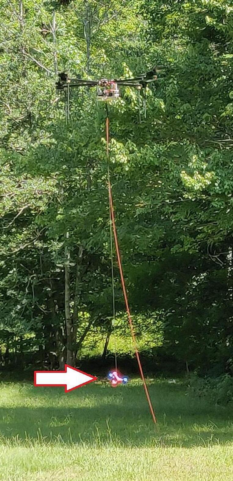
Tether powered UAV lifting bundle of hand weights for payload vs power measurement.
The power consumed by the UAV is determined internally by the PixHawk software. The voltage and current parameters are reported to the GCS through a standard telemetry link. The difference between these two power measurements is due to the transmission loss from the resistance of the tether wire and inefficiencies of the DC-DC converters at the top of the tether.
As can be seen in Fig. 30, the transmission loss increases, as expected, with increasing current, thus corroborating the design decision of using high voltage and low current in order to minimize transmission losses.
Fig. 30.

Power required and payload lifted. Multiple payloads are flown by an efficient UAV with power measurements taken at the base and at the UAV. The difference is displayed as transmission loss due to tether resistance and DC-DC converter inefficiency. Maximum power at the base of 1030 W delivers 830 W to the UAV for a maximum payload of 4778 g, including tether weight.
The measured maximum payload for this UAV can be seen in Fig. 30 at the far right where the base power is 1030 W and the UAV power is 830 W. This data point corresponds to 4778 g of payload for this UAV. This measurement is taken at low altitude with very little tether mass adding to the payload total. The full 120 m 22 awg silicone jacketed copper tether weighs 1240 g so the payload at the UAV would need to be reduced by this amount if flown at the full height. Intermediate heights would incur proportionally less impact. See Table 4. The maximum payloads under conditions different from those that have been tested can be extrapolated from the collected empirical data. The necessary power figure at the base and the resulting power available to the UAV as a function of payload can be formulated as second order polynomials, which are provided in Fig. 30, where X corresponds to the payload, including tether, and y to the power.
While the tether can power any copter-style UAV, the payload lifting performance depends on the efficiency of that particular design. The power required to payload lifted ratio can be easily measured by noting the voltage and current reported by the UAV and the weight of various payloads. In this manner, an estimate of the payload that could be lifted while using tether power can be calculated for any UAV.
Payloads in this range, with persistent tether-supplied power, enable a multitude of research opportunities. Any situation where an elevated research platform is required for an extended period of time would benefit from this tool. For example, the integration of UAVs into the cellular system is ongoing and requires lengthy testing of signal propagation and interference measurements [9].
This design is the culmination of several previous attempts with improvements ensuring a robust and trustworthy power supply. Preliminary prototypes suffered from insufficient PCB trace width and insufficient cooling of the airborne DC-DC converters. Subsequent redesign of the top PCB to increase trace width and include duplicate traces on the bottom layer for high current (after the DC-DC converters) eliminated the trace burn-through issue. Improved heatsinks and the addition of cooling fans eliminated the DC-DC converter overheating problem. The overheating and subsequent shutdown of the converters while inflight necessitated the transfer to rescue battery power, thus affirming the wisdom of that feature. At high altitudes with long lengths of cable hanging below the UAV, some oscillations occurred while descending. This instability is corrected by tweaking the autopilot settings to favor stability over maneuverability.
In summary, a robust design for a tether UAV power supply is presented with the following features:
-
•
Maximum payload in the 3.5–6.2 kg range.
-
•
Very low cost compared to commercial heavy-lift tether systems.
-
•
Top PCB is designed for 1, 2, or 3 DC-DC converters allowing for greater payloads where 220 AC is available.
-
•
Fast set up and takedown time (approximately 15 min).
-
•
Remote monitoring and control is available with Xbee radio link and custom GUI.
-
•
Can be fitted to any copter style UAV.
-
•
Emergency battery allows for controlled landing in the event of tether failure.
-
•
Usefulness is only limited by no/low horizontal maneuverability.
Ethics statements
Human and animal rights: Not applicable.
CRediT authorship contribution statement
Andrew Yingst: Conceptualization, Methodology, Software, Validation, Formal analysis, Visualization, Writing – original draft. Vuk Marojevic: Supervision, Project administration, Funding acquisition, Writing – review & editing.
Declaration of Competing Interest
The authors declare that they have no known competing financial interests or personal relationships that could have appeared to influence the work reported in this paper.
Acknowledgments
This project was in part supported by the Office of Naval Research award N00014-20-1-2323. Yingst and V. Marojevic are supported in part by the National Science Foundation under grant number CNS-1939334.
Biographies

Andrew Yingst (aly112@msstate.edu) is a Ph.D. candidate in the ECE Department at Mississippi State University-Starkville. He graduated from the United States Air Force Academy with a BS in Electrical Engineering. His research interests include long-range UAV operations and tethered UAV power systems.

Vuk Marojevic (vuk.marojevic@ece.msstate.edu) is an associate professor in Electrical and Computer Engineering at Mississippi State University, Starkville, MS, USA. He graduated from University of Hannover, Germany, and Barcelona Tech (UPC), Spain, with an MS and a Ph.D in electrical engineering. He is a principal investigator of the NSF projects AERPAW and Open Artificial Intelligence Cellular (OAIC). His research interests include mobile communications, software radios, spectrum sharing, wireless testbeds and testing, and wireless security with application to mission-critical communications, open radio access network, and unmanned aircraft systems. He is an associate editor of the IEEE Transactions on Vehicular Technology and the IEEE Vehicular Technology Magazine.
Contributor Information
Andrew Yingst, Email: aly112@msstate.edu.
Vuk Marojevic, Email: vuk.marojevic@ece.msstate.edu.
References
- 1.Lifeline. LifelineTethered Drone. https://www.lifeline-drone.com/. 2018(accessed 07.17.22).
- 2.Volarious. V-Line Actively Tethered Drone System. https://www.volarious.com/vline-actively-tethered-drone-system-portable. 2021(accessed 07.17.22).
- 3.D. Rico, “Power-over-Tether Unmanned Aerial System Leveraged for Trajectory Influenced Atmospheric Sensing” (2021). Computer Science and Engineering: Theses, Dissertations, and Student Research. 212. https://digitalcommons.unl.edu/computerscidiss/212.
- 4.L. Yingst and V. Marojevic, “Tethered UAV with High Gain Antenna for BVLOS CNPC: A Practical Design for Widespread Use,” 2021 IEEE 22nd International Symposium on a World of Wireless, Mobile and Multimedia Networks (WoWMoM), 2021, pp. 323-328, 10.1109/WoWMoM51794.2021.00059. [DOI]
- 5.Elistair. Safe-T 2. https://elistair.com/safe-t-tethered-drone-station/. 2019(accessed 07.17.22).
- 6.TDK. https://product.tdk.com/system/files/dam/doc/product/power/switching-power/ac-dc-converter/specification/pf1000a_spc.pdf. (accessed 07.17.22).
- 7.Itead Studios. MotoMama. https://wiki.iteadstudio.com/MotoMama. 2016 (accessed 07.22.22).
- 8.Vicor. DCM™ DC-DC Converter Isolated, Regulated DC Converter DCM4623xD2K31E0yzz. https://www.vicorpower.com/documents/datasheets/DCM4623xD2K31E0yzz_ds.pdf. 2020 (accessed 07.17.22).
- 9.Abdalla A.S., Yingst A., Powell K., Gelonch-Bosch A., Marojevic V. Open source software radio platform for research on cellular networked UAVs: it works! IEEE Commun. Mag. 2022;60(2):60–66. doi: 10.1109/MCOM.001.2100394. [DOI] [Google Scholar]