

Abstract
In this paper, a novel 8-shaped resonator coupled to metal–insulator–metal waveguides is used for designing plasmonic filters and sensors. The resonator supports two resonance modes, which result in peaks in the transmission spectrum of the structure. A Q-factor of 247.4 which can reach up to 270 at the wavelength of 1187.5 nm is observed. By placing vertical and horizontal metal blades in the resonator, two tunable single-mode plasmonic filters are obtained at the first and second resonance modes, respectively. The effect of structural parameters on the transmission spectrum is investigated using the finite-difference time-domain (FDTD) method. Based on the obtained results, the proposed plasmonic structure can be used for biosensing applications such as the detection of basal cancer cells with a sensitivity of 1200 nm/RIU. It is of great significance that both the sensitivity and Q-factor values for the proposed structure are higher than most recent sensors reported in the literature. Therefore, the proposed structure is a potentially promising candidate for filtering and sensing applications.
Subject terms: Integrated optics, Optical sensors
Introduction
Over the past decade, surface plasmon polaritons (SPPs) have attracted significant interest due to their unique properties, such as propagating along metal–dielectric interfaces1. With SPPs, optical signals can be confined and controlled at a nanoscale level, thus overcoming the traditional diffraction limit of dielectric waveguides2,3. Optical SPPs are considered to be a promising information carrier for ultra-high density photonic integrated circuits of the next generation4. Metal–insulator–metal (MIM) waveguide structures are one of the most commonly used SPP-based structures for the realization of highly integrated optical circuits. A MIM structure has the advantages of providing deep sub-wavelength confinement of light and good balance between propagation length and loss, as well as ease of integration on a microchip5,6. Today, many plasmonic structures have been designed for a wide range of applications, including filters7–9, sensors10–18, demultiplexers19,20, switches21–23, logic gates24, etc. Although these structures can be realized using other techniques such as silicon photonic technology or photonic crystals, plasmonic structures occupy a much smaller area compared to the mentioned platforms25,26.
Since the properties of plasmonic MIM waveguides and filters are highly dependent upon the refractive index of the insulator material, they can be utilized to measure refractive index changes of the environment27. Thus, plasmonic MIM structures provides significant advantages for subwavelength refractive index sensing28. There is a great deal of interest in optical sensors due to the wide range of applications they have. Biomedical applications are one of the most significant uses of optical sensors. In particular, these sensors may be used in biosensing applications such as the detection of cancer cells, health care applications, measurement of blood components, etc.29–33. Optical sensors have been designed using a variety of approaches and based on various configurations, such as plasmonic34–38, photonic crystal39–42, graphene43–50, optical fiber topologies51–55 such as fiber Bragg grating, long period grating, SMS fiber structure, fiber in-line M–Z interferometer, F–P cavity, etc. Plasmonic sensors based on MIM waveguides have drawn a lot of attention because they have a smaller footprint and stronger sensing capabilities compared with other sensing techniques. Due to their small size, simplicity of integration, and good balance between light localization and transmission loss, plasmonic sensors are a good candidate to produce highly integrated optical circuits. Plasmonic sensors offer several unique advantages such as label-free detection, high sensitivity, rapid response, real-time monitoring, strong amplification of a local electric field, spectral tunability and compliance with nanotechnology56. Despite these advantages, they have some limitations such as limited penetration depth, limited selectivity and limited reproducibility. The fabrication of sensors based on metallic nanostructures can be challenging. Small variations in the geometry of the structure, and changes in temperature, humidity, and pH can affect the sensor response. Notwithstanding these limitations, plasmonic sensors have found many applications in different fields. Hence, researches are being done to develop and improve the performance and capabilities of these structures by eliminating these limitations56,57.
In this paper, three topologies are proposed, which consist of two MIM waveguides coupled to each other by an 8-shaped resonator. First, a tunable plasmonic filter structure based on the 8-shaped resonator is investigated which supports two resonances. Then, to provide a tunable single-mode filter, the second and third structures are proposed to support the first and second resonances, respectively. The performance of the proposed structures is evaluated by the finite difference time domain (FDTD) method. Finally, the performance of the third structure as a high-sensitivity plasmonic refractive index biosensor is evaluated for detection of basal cancer cell which is responsible for causing skin cancer in human body. The resonance wavelengths of a ring resonator depend on the optical path of the ring resonator and the mode order. The optical path is defined as 2πRneff, where R is the radius, and neff is the effective refractive index. An 8-shaped resonator occupies less area compared to a circular or a ring-shaped resonator with the same circumference, which leads to a smaller footprint. Here, we first investigate the behavior of the 8-shaped resonator and observe the resonance modes and later we modify the resonator to make it single-mode. In the first structure, the overlap of two resonances may complicate spectral identification when the resonances are shifted. Hence, the first structure is not optimum for sensing applications that need reliable and accurate spectral shifts. For sensing applications, a single-mode resonance is preferred. For this reason, we have modified the 8-shaped resonator and proposed the second and third structures which exhibit a single-mode resonance. The proposed plasmonic structure can be fabricated using electron beam lithography (EBL) with adequate exposure time and focused ion beam (FIB) technique58. Generally, the fabrication of plasmonic structures can be costly and time-consuming, which can limit their use in some specific applications56.
The current paper is organized as follows: in “The proposed structure and analysis method”, the proposed structure is described and the analysis method is theoretically presented In “Results and discussion”, the simulation results are discussed. Finally, in “Biosensing application”, we will have a conclusion.
The proposed structure and analysis method
Figure 1 shows the structure of the first proposed plasmonic filter (marked as structure A), which consists of two MIM waveguides coupled to each other by an 8-shaped resonator. Here, in the 8-shaped resonator, two cross-passing waveguides are combined with two upper and lower circular rings. The filter’s geometric parameters are the waveguide width (), the width of resonator waveguide (), the length of resonator cross-passing waveguides (), the radius of resonator rings (), the angle of resonator rings (), the distance between the center of the resonator and the lateral MIM waveguides () and the angle between the resonator branches and the horizontal line (). All of the filter’s geometrical parameters are summarized in Table 1. In this plasmonic MIM structure, the insulator or dielectric material is assumed to be air, and the metal is assumed to be silver.
Figure 1.
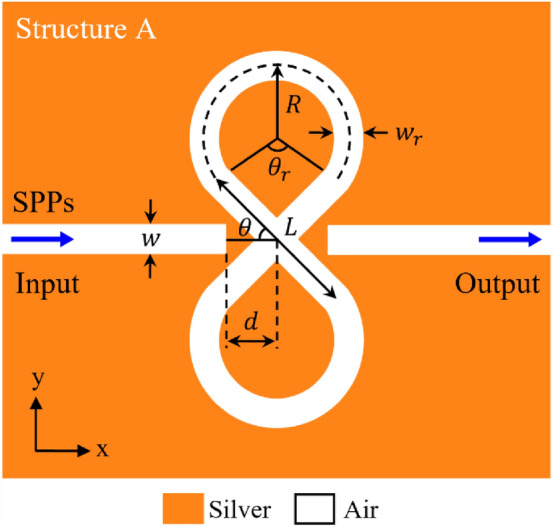
Schematic of the first proposed plasmonic filter (marked as structure A) consisting of two MIM waveguides coupled to each other by an 8-shaped resonator.
Table 1.
the geo metrical parameters of the first proposed plasmonic filter (marked as structure A).
| Parameter | Symbol | Value |
|---|---|---|
| Waveguide widths | ||
| Width of resonator waveguide | ||
| Length of resonator cross-passing waveguides | ||
| Radius of resonator rings | ||
| The distance between the center of resonator and the lateral MIM waveguides | ||
| Angle of resonator rings | ||
| Angle between the resonator branches and the horizontal line |
Since the width of the input waveguide is much smaller than the incident wavelength (), only the fundamental transverse magnetic (TM) mode as in the waveguide can exist. For the fundamental TM mode, the dispersion relation of SPPs in the MIM waveguide structures can be expressed as59:
| 1 |
where and are the relative permittivity of the dielectric and metal, respectively. and are defined by momentum conservations as follows59:
| 2 |
where stands the SPP propagation constant. can be calculated using Eqs. (1) and (2). is the wave vector in a vacuum. In general, air has a refractive index (n) of 1, while its relative permittivity is = 1. The complex relative permittivity of silver is characterized by the well-known Drude model as follows10:
| 3 |
where = 3.7 is the dielectric constant at the infinite frequency, = 9.1 eV is the bulk plasma frequency, = 0.018 eV is the electron collision frequency, is the angular frequency of the incident wave, and is the speed of light in free space.
The effective refractive index () of the fundamental TM mode in the MIM waveguide as a function of wavelength can be solved from . The real part of effective refractive index determines the guided wavelength in MIM waveguide () and its imaginary part determines the propagation length of SPPs (). Therefore, the effective refractive index () can be characterized as follows60:
| 4 |
| 5 |
Based on the above principles, we have calculated the real part of and for different widths of MIM waveguides as shown in Fig. 2a,b, respectively. To support only the fundamental TM mode in the MIM waveguide, we set , which is much smaller than the operating wavelengths. Two power monitors are set at input and output ports to detect the incident power and the transmitted power , respectively. The power transmittance is defined as .
Figure 2.

(a) Real part of the effective refractive index () and (b) The corresponding propagation length of SPPs () as a function of wavelength for different widths of the air layer in the MIM waveguide.
Ethical approval
We the undersigned declare that the manuscript entitled “A single-mode tunable plasmonic sensor based on an 8-shaped resonator for cancer cell detection” is original, has not been fully or partly published before, and is not currently being considered for publication elsewhere. Also, results are presented clearly, honestly, and without fabrication, falsification, or inappropriate data manipulation. We confirm that the manuscript has been read and approved by all named authors and that there are no other persons who satisfied the criteria for authorship but are not listed. We further confirm that the order of authors listed in the manuscript has been approved by all of us.
Results and discussion
The finite-difference time-domain (FDTD) method is used to calculate the transmission response of the proposed plasmonic filter. FDTD method is a time-domain solution that solves Maxwell's equations without applying any physical approximation. This method solves Maxwell's equations numerically on a mesh by adopting appropriate boundary conditions. Therefore, the electric and magnetic fields are calculated for all grid points. The perfectly matched layer (PML) boundary conditions are defined at the x- and y-directions of the simulation domain. To propagate SPPs in the waveguide, a mode source as the input light source is launched to the input port of waveguide. Then, a transmission monitor is placed in the output port of waveguide to detect the spectrum transmitted signal. In all directions, the mesh size is set as 2 nm.
Figure 3a shows the transmission spectrum of the first proposed plasmonic filter with an 8-shaped resonator when , , , , , and . It is observed that there are two resonance modes within the wavelength range of 1000–2000 nm, the first at 1136.4 nm and the second at 1187.5 nm. The first resonance mode has a maximum transmission value of about 100% with an FWHM (full width at half the maximum) bandwidth of about 9 nm. Besides, the second resonance mode has a maximum transmission value of about 80% with an FWHM (full width at half the maximum) bandwidth of about 4.8 nm. Plasmonic filters usually have a broad FWHM bandwidth due to having a larger propagation loss.
Figure 3.

(a) The transmission spectrum of the first proposed plasmonic filter (marked as structure A) with an 8-shaped resonator when 50 nm, 50 nm, 310 nm, 130 nm, 110°, 85 nm and 45°. (b) The Re(Hz) field pattern of the plasmonic filter at the first resonance wavelength of 1136.4 nm. (c) The Re(Hz) field pattern of the plasmonic filter at the second resonance wavelength of 1187.5 nm.
To investigate the performance of a resonator, the quality factor (Q-factor) is usually calculated. A lossless or ideal resonator is measured by this parameter. The Q-factor is defined as the ratio of a resonator's resonance wavelength to its bandwidth ()61. In plasmonic resonators, the Q-factor is typically limited by the intrinsic ohmic losses of the metal. Q-factor values of 126.3 and 247.4 have been calculated for the first and second resonance modes.
Figure 3b,c show the electromagnetic field profile in the z-direction (Re(Hz)) for the first proposed plasmonic filter at the 1st and 2nd resonance modes, respectively. As can be seen in the figure, the vivid resonances are created in the 8-shaped resonator. It is evident that the 1st and 2nd resonance modes, respectively originate from the even and odd modes of the electromagnetic field.
To determine the resonance wavelengths in the plasmonic filter, the condition of resonance can be written as60:
| 6 |
where is an integer number, which represent the mode numbers. The length of the 8-shaped resonator () is calculated as . In this regard, the wavelength associated with each resonance modes will be:
| 7 |
Using Eqs. (5) and (7), the resonance wavelengths can be calculated as follows:
| 8 |
According to Eq. (8), for a specific , increasing the dimensions of the resonator length causes the redshift of resonance wavelengths. Therefore, increasing the length of resonator cross-passing waveguides () and the radius of resonator rings () shifts the resonance wavelengths of the filter to higher wavelengths. Hence, the wavelength can be adjusted by changing the parameters of the resonator. It is essential that a high-quality filter be tunable.
We study the effect of geometric parameters on the transmission spectrum in order to obtain the optimal dimensions of filter structure A. In this regard, we investigate the effects of the width of the resonator waveguide () and the distance between the center of the resonator and the lateral MIM waveguides () in Figs. 4 and 5, respectively. Figure 4a shows the effect of on the transmission spectrum of the filter and the corresponding resonance wavelengths. The size is increased from 35 to 65 nm by a 5 nm step. The other geometric parameters remain unchanged. As shown in Fig. 4b, increasing the size results in a redshift toward lower wavelengths in the 1st and 2nd resonance modes. The wavelengths of both resonance modes decrease linearly with a slope of about 15.5%. It occurs because the effective refractive index declines with increasing the size. As a result, according to Eq. (7), the resonance wavelength also decreases. Figure 4c shows the Q-factor of the 1st and 2nd resonance wavelengths of the filter structure A as a function of size. Increasing the size results in a sharp reduction of the Q-factor of the first resonance mode from 245 to 65, as well as a decrease of the Q-factor of the second resonance mode from 255 to 160. However, based on Fig. 4a, as the Q-factor is decreased, the transmission peak value is increased when the size is increased. Consequently, a trade-off is seen between increasing the Q-factor and reducing maximum transmission.
Figure 4.

(a) The transmission spectrum of the first proposed plasmonic filter (marked as structure A) for different widths of resonator waveguide (). (b) The first and second resonance wavelengths as a function of the size. (c) The Q-factor of the 1st and 2nd resonance modes as a function of the size.
Figure 5.

(a) The transmission spectrum of the first proposed plasmonic filter (marked as structure A) for different the distances between the center of resonator and the lateral MIM waveguides (). (b) The first and second resonance wavelengths as a function of the size. (c) The Q-factor of the 1st and 2nd resonance modes as a function of the size.
Figure 5a shows the effect of on the transmission spectrum of filter structure A and the corresponding resonance wavelengths. The size is increased from 70 to 100 nm in a 5 nm step. The other geometric parameters remain unchanged. As shown in Fig. 5b, as the size is increased, the 1st and 2nd resonance wavelengths shift toward lower wavelengths. Wavelengths decrease almost linearly in the 1st and 2nd resonance modes with slopes of approximately 0.2% and 2%, respectively. Figure 5c shows the Q-factor of the 1st and 2nd resonance wavelengths of the filter as a function of size. Increasing the size results in a sharp increase in the Q-factor of the first and second resonance modes, which reaches a maximum value of about 270 for . Boosting the Q-factor is physically justified according to coupled-mode theory. As the distance between the resonator and the waveguides is increased, the resonance mode will leak less into the waveguides. Therefore, the Q-factor is increased by increasing the size. However, from Fig. 5a, as the Q-factor is increased, transmission peak value is decreased when the size is increased. As a result, there is a trade-off between increasing Q-factor and decreasing maximum transmission.
The high-Q plasmonic filter using the 8-shaped resonator (marked as structure A) can be used for sensing applications. However, this structure provides two resonance modes. The overlap of these resonances can complicate spectral identification when the resonances are shifted. Because, two spectra begin to merge and makes monitoring spectral changes difficult. Hence, the second and third structures supporting the single-mode resonance are proposed.
As described previously, the 1st and 2nd resonance modes of the first proposed plasmonic filter (marked as structure A) are derived from the even and odd modes of the electromagnetic field excited in the resonator. To eliminate the odd mode of electromagnetic field, we placed the vertical metal gaps in the 8-shaped resonator. By removing the odd mode, the second resonance mode is eliminated and only the first resonance mode is preserved as a single-mode resonance. Hence, Fig. 6a shows the schematic of the second proposed plasmonic filter (marked as Structure B) consisting of the vertical metal gaps in 8-shaped resonator with a width of . Figure 6b shows the comparison of the transmission spectrum of the plasmonic filter structures A and B. For filter structure B, the width of metal gap is set to be , while other geometric parameters are based on Table 1. For filter structure B, it can be seen that the 2nd resonance mode is removed and only the 1st resonance mode is preserved. Therefore, the second proposed plasmonic filter provides a tunable single-mode resonance at a wavelength of 1136.4 nm.
Figure 6.

(a) Schematic of the second proposed plasmonic filter (marked as Structure B) consisting of the vertical metal gaps in the 8-shaped resonator with a width of . (b) The transmission spectrum of the filter structure B supporting a single-mode resonance at the wavelength of 1136.4 nm.
Furthermore, to eliminate the even mode of electromagnetic field, we placed two horizontal metal gaps in the 8-shaped resonator. By removing the even mode, the 1st resonance mode is eliminated and only the 2nd resonance mode is preserved as a single-mode resonance. In this regard, Fig. 7a shows the schematic of the third proposed plasmonic filter (marked as Structure C) consisting of the horizontal metal gaps in the 8-shaped resonator with a width of . Figure 7b shows the comparison of the transmission spectrum of the plasmonic filter structures A and C. For filter structure C, the width of metal gap is set to be , and the distance between the center of the resonator and the horizontal metal gap is . Other geometric parameters are based on Table 1. For filter structure C, it can be seen that the fist resonance mode is removed and only the second resonance mode is preserved. Therefore, the third proposed plasmonic filter provides a tunable single-mode resonance at the wavelength of 1187.5 nm.
Figure 7.

(a) Schematic of the third proposed plasmonic filter (marked as Structure C) consisting of the horizontal metal gaps in the 8-shaped resonator with a width of . (b) The transmission spectrum of the filter structure C supporting a single-mode resonance at the wavelength of 1187.5 nm.
Figure 8a shows the effect of varying on the transmission spectrum of filter structure B and the corresponding 1st resonance single-mode wavelength. The size is increased from 0 to 25 nm in a 5 nm step. The other geometric parameters of filter structure B are fixed. As seen, by incrementing size, the 1st single-mode wavelength shifts toward lower wavelengths. Single-mode resonance at a wavelength of 1136.4 nm can be achieved for . Moreover, Fig. 8b shows the effect of varying on the transmission spectrum of filter structure C and the corresponding 2nd resonance single-mode wavelength. The size is increased from 0 to 25 nm in a 5 nm step. The other geometric parameters of filter structure C are fixed. As seen, increasing size results in the shift toward lower wavelengths for the 2nd single-mode wavelength. Therefore, single-mode resonance at a wavelength of 1187.5 nm can be achieved for .
Figure 8.
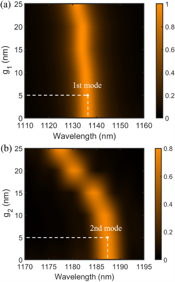
(a) The transmission spectrum of the second proposed plasmonic filter (marked as structure B) for different widths of vertical metal gap (). (b) The transmission spectrum of the third proposed plasmonic filter (marked as structure C) for different width of horizontal metal gap ().
Biosensing application
In this section, it is shown that third proposed tunable plasmonic filter structure can be used for biosensing applications such as the detection of basal cancer cell. Basal cancerous cell is responsible for skin cancer in human body. The cancerous tumor has a refractive index of 1.38, while the normal basal cell has a refractive index of 1.3662. The change in the refractive index from normal to cancer cell is very small. To detect this change the sensor design must be highly sensitive. Since the refractive indices of human cells are measured in the near infrared range, the proposed tunable filter structure can be used for sensing normal and cancerous cells. Figure 9a shows the transmission spectrum of third proposed plasmonic filter corresponding to the normal basal cell and basal cancer cell. The refractive index variation occurs in the surrounding environment of structure after proximity to the cells. Consequently, changing the refractive index shifts the resonance wavelength in the transmission spectrum of the sensor structure. As seen, the resonance wavelength shift in the transmission spectrum of third proposed structure is 24 nm. To investigate the sensing performance of proposed biosensor structure, the sensitivity (S) parameter is calculated. The sensitivity (S) of sensor is defined as the ratio of the resonance wavelength shift to the refractive index variation ()63. Figure 9b shows a linear relationship between the resonance wavelength and the environment refractive index variations from n = 1.3 to 1.6 in the near infrared range. As can be seen, the calculated slope of the linear fit line estimates the sensitivity of sensor. Hence, the sensitivity value of 1200 nm/RIU is obtained. Therefore, the third proposed plasmonic filter structure as a plasmonic biosensor can be a good candidate for the detection of basal cancer cell.
Figure 9.

(a) The transmission spectrum of third proposed plasmonic filter (marked as structure C) corresponding to the normal basal cell and basal cancer cell. (b) Resonance wavelength of the proposed third structure as a function of environment refractive indices.
To provide a better view of the obtained results in this paper, the third proposed plasmonic structure (marked as structure C) is compared with other reported works in recent years. For comparison, Table 2 shows some main characteristics of refractive index plasmonic sensors based on MIM waveguides. The comparison parameters include the filter shapes, topologies, Detection, resonance wavelength (), Q-factor, and sensitivity. Our proposed plasmonic structure is a tunable filter that exhibits single-mode behavior in the 1000–2000 nm range. The resonance wavelength can be adjusted by changing the structural parameters of the resonator. The proposed tunable filter has a Q-factor of 247.4, which is higher than most of the works presented in Table 2. Moreover, this structure can be used as a plasmonic biosensor for the detection of basal cancer cells. It depicts the highest sensitivity of 1200 (nm/RIU) among the many published sensor structures in this table. In most plasmonic sensors, the sensitivity and Q-factor are not simultaneously improved. It can be seen, our proposed structure is clearly superior both in terms of sensitivity as well as Q-factor to most recent sensors reported.
Table 2.
Comparison of the sensing performance of the proposed plasmonic biosensor with other works.
| References | Year | Setup | Topology | Detection application | (nm) | Q-factor | Sensitivity (nm/RIU) |
|---|---|---|---|---|---|---|---|
| 4 | 2016 | MIM | Double rectangular cavities | General | 620 | – | 596 |
| 64 | 2017 | MIM | Rectangular side-coupled with a disk cavity | General | 1148.5 | 85.77 | 1136 |
| 65 | 2017 | MIM | Two silver baffles and a coupled ring cavity | General | 710 | – | 718 |
| 66 | 2018 | MIM | Pair of elliptical ring resonators | Hemoglobin | ≃1004 | 200.8 | 1100 |
| 67 | 2019 | MIM | Si nano-ring located inside a circular cavity | General | 808 | 269.3 | 636 |
| 68 | 2019 | MIM | Tooth cavity-coupled ring splitting cavity | General | 1055 | 107.32 | 1200 |
| 69 | 2019 | MIM | Side-coupled stub-hexagon resonators | General | 915 | 140.122 | 937.5 |
| 70 | 2020 | MIM | Two rectangular nanocavities coupled to a Bus waveguide and two nanodisk resonators | General | 796 | 21.84 | 750 |
| 31 | 2020 | MIM | Three quadrilateral cavities sandwiched perpendicularly in between the MIM waveguides | Blood group | 1651 | ≃ 15.7 | 1556 |
| 71 | 2021 | MIM | An asymmetric cross-shaped resonator | General | 839 | – | 795 |
| 72 | 2021 | MIM | Two sequential ring resonators | General | 998.8 | 132.8 | 1000 |
| 73 | 2021 | MIM | Three H-shaped cavities | General | 1056.4 | 69.91 | 1050 |
| 74 | 2022 | MIM | Split-ring Heptamer structures | General | 1600 | – | 840 |
| This work (Structure C) | 2023 | MIM | 8-shaped resonator | Basal cancer cells | 1187.5 | 247.4 | 1200 |
Conclusions
In this paper, a tunable plasmonic filter, which consists of two MIM waveguides coupled to each other by an 8-shaped resonator was designed and investigated. This structure had two resonance modes at wavelengths of 1136.4 nm and 1187.5 nm in the 1000–2000 nm range. The calculated Q-factor for resonance modes was obtained equal to 126.3 and 247.4, respectively. The performance of the structure was also theoretically analyzed. Then, by placing metal gaps in the vertical and horizontal directions of the resonator, two tunable single-mode plasmonic filters, to support each of the former resonance modes, were proposed. Finally, the proposed structure with the horizontal metal gaps was investigated for sensing applications. The effect of structural parameters on the transmission spectrum and the sensing performance of the sensor were investigated using the finite-difference time-domain (FDTD) method. Based on the obtained results, this structure can be used to detect the basal cancer cells with a sensitivity of 1200 nm/RIU. The main drawback of many plasmonic sensors is that both sensitivity and Q-factor are not improved simultaneously. While for our proposed structure, they are much better than the many recently reported sensors. Accordingly, the work presented in this paper is a suitable candidate for filtering and sensing applications in optic communications.
Acknowledgements
The authors would like to thank the editor and the reviewers for their valuable comments.
Author contributions
Design, analysis, and investigation: M.D., L.H., E.G., writing—original draft preparation: L.H., writing—review and editing: L.H., M.D., supervision: M.D.
Data availability
The datasets generated and analyzed during the current study are available from the corresponding author on reasonable request.
Competing interests
The authors declare no competing interests.
Footnotes
Publisher's note
Springer Nature remains neutral with regard to jurisdictional claims in published maps and institutional affiliations.
References
- 1.Hajshahvaladi L, Kaatuzian H, Moghaddasi M, Danaie M. Hybridization of surface plasmons and photonic crystal resonators for high-sensitivity and high-resolution sensing applications. Sci. Rep. 2022;12:21292. doi: 10.1038/s41598-022-25980-y. [DOI] [PMC free article] [PubMed] [Google Scholar]
- 2.Maier SA. Plasmonics: Fundamentals and Applications. Springer; 2007. [Google Scholar]
- 3.Zhang Z, Yang J, He X, Zhang J, Huang J, Chen D, et al. Plasmonic refractive index sensor with high figure of merit based on concentric-rings resonator. Sensors. 2018;18:116. doi: 10.3390/s18010116. [DOI] [PMC free article] [PubMed] [Google Scholar]
- 4.Zhang Z, Luo L, Xue C, Zhang W, Yan S. Fano resonance based on metal-insulator-metal waveguide-coupled double rectangular cavities for plasmonic nanosensors. Sensors. 2016;16:642. doi: 10.3390/s16050642. [DOI] [PMC free article] [PubMed] [Google Scholar]
- 5.Ebbesen TW, Genet C, Bozhevolnyi SI. Surface-plasmon circuitry. Phys. Today. 2008;61:44. doi: 10.1063/1.2930735. [DOI] [Google Scholar]
- 6.Chau Y-FC, Chao C-TC, Chiang H-P. Ultra-broad bandgap metal–insulator–metal waveguide filter with symmetrical stubs and defects. Results Phys. 2020;17:103116. doi: 10.1016/j.rinp.2020.103116. [DOI] [Google Scholar]
- 7.Qi Y, Zhou P, Zhang T, Zhang X, Wang Y, Liu C, et al. Theoretical study of a multichannel plasmonic waveguide notch filter with double-sided nanodisk and two slot cavities. Results Phys. 2019;14:102506. doi: 10.1016/j.rinp.2019.102506. [DOI] [Google Scholar]
- 8.Zhu H, Zhang Y, Ye L, Li Y, Xu Y, Xu R. On-chip terahertz bandpass filter based on substrate integrated plasmonic waveguide. Results Phys. 2021;27:104553. doi: 10.1016/j.rinp.2021.104553. [DOI] [Google Scholar]
- 9.Afroozeh A. Numerical and analytical modeling of plasmonic filter with high Q-factor based on “nanostructured resonator”. Plasmonics. 2022;17:371–379. doi: 10.1007/s11468-021-01527-1. [DOI] [Google Scholar]
- 10.Hajshahvaladi L, Kaatuzian H, Danaie M, Karimi Y. Design of a highly sensitive tunable plasmonic refractive index sensor based on a ring-shaped nano-resonator. Opt. Quant. Electron. 2022;54:1–17. doi: 10.1007/s11082-021-03431-8. [DOI] [Google Scholar]
- 11.Saylan Y, Akgönüllü S, Denizli A. Plasmonic sensors for monitoring biological and chemical threat agents. Biosensors. 2020;10:142. doi: 10.3390/bios10100142. [DOI] [PMC free article] [PubMed] [Google Scholar]
- 12.Chao C-TC, Chau Y-FC, Chiang H-P. Multiple Fano resonance modes in an ultra-compact plasmonic waveguide-cavity system for sensing applications. Results Phys. 2021;27:104527. doi: 10.1016/j.rinp.2021.104527. [DOI] [Google Scholar]
- 13.Hedhly M, Wang Y, Zeng S, Ouerghi F, Zhou J, Humbert G. Highly sensitive plasmonic waveguide biosensor based on phase singularity-enhanced Goos-Hänchen shift. Biosensors. 2022;12:457. doi: 10.3390/bios12070457. [DOI] [PMC free article] [PubMed] [Google Scholar]
- 14.Nasirifar R, Danaie M, Dideban A. Highly sensitive surface plasmon resonance sensor using perforated optical fiber for biomedical applications. Optik. 2022;250:168051. doi: 10.1016/j.ijleo.2021.168051. [DOI] [Google Scholar]
- 15.Butt MA. Plasmonic sensor realized on metal-insulator-metal waveguide configuration for refractive index detection. Photon. Lett. Pol. 2022;14:1–3. doi: 10.4302/plp.v14i1.1122. [DOI] [Google Scholar]
- 16.Ye H-Y, Huang X-Q, Wen K-H, Xue J-C, Zhou J-Y, Meng Z-M. Near-infrared narrow plasmonic resonances for high-performance optical sensing in a sodium-based nanograting. Results Phys. 2022;38:105566. doi: 10.1016/j.rinp.2022.105566. [DOI] [Google Scholar]
- 17.Nickpay M-R, Danaie M, Shahzadi A. Graphene-based tunable quad-band fan-shaped split-ring metamaterial absorber and refractive index sensor for THz spectrum. Micro Nanostruct. 2023;173:207473. doi: 10.1016/j.micrna.2022.207473. [DOI] [Google Scholar]
- 18.Zhang X, Yan S, Li T, Liu P, Zhang Y, Shen L, et al. Refractive index sensor based on Fano resonance in a ring with a rectangular cavity structure. Results Phys. 2021;31:104997. doi: 10.1016/j.rinp.2021.104997. [DOI] [Google Scholar]
- 19.Hajshahvaladi L, Kaatuzian H, Danaie M. Design and analysis of a plasmonic demultiplexer based on band-stop filters using double-nanodisk-shaped resonators. Opt. Quant. Electron. 2019;51:391. doi: 10.1007/s11082-019-2108-1. [DOI] [Google Scholar]
- 20.Mohammadi M, Soroosh M, Farmani A, Ajabi S. Engineered FWHM enhancement in plasmonic nanoresonators for multiplexer/demultiplexer in visible and NIR range. Optik. 2023;20:170583. doi: 10.1016/j.ijleo.2023.170583. [DOI] [Google Scholar]
- 21.Karimi Y, Kaatuzian H, Tooghi A, Danaie M. All-optical plasmonic switches based on Fano resonance in an X-shaped resonator coupled to parallel stubs for telecommunication applications. Optik. 2021;243:167424. doi: 10.1016/j.ijleo.2021.167424. [DOI] [Google Scholar]
- 22.Heidari S, Nozhat N. Wideband polarization-independent plasmonic switch based on GST phase-change material. Appl. Opt. 2022;61:4068–4073. doi: 10.1364/AO.456423. [DOI] [PubMed] [Google Scholar]
- 23.Khani S, Danaie M, Rezaei P. All-optical plasmonic switches based on asymmetric directional couplers incorporating Bragg gratings. Plasmonics. 2020;15:869–879. doi: 10.1007/s11468-019-01106-5. [DOI] [Google Scholar]
- 24.Moradi M, Danaie M, Orouji AA. All-optical NOR and NOT logic gates based on ring resonator-based plasmonic nanostructures. Optik. 2022;258:168905. doi: 10.1016/j.ijleo.2022.168905. [DOI] [Google Scholar]
- 25.Danaie M, Kiani B. Design of a label-free photonic crystal refractive index sensor for biomedical applications. Photon. Nanostruct. Fundam. Appl. 2018;31:89–98. doi: 10.1016/j.photonics.2018.06.004. [DOI] [Google Scholar]
- 26.Hajshahvaladi L, Kaatuzian H, Danaie M. Design of a hybrid photonic-plasmonic crystal refractive index sensor for highly sensitive and high-resolution sensing applications. Phys. Lett. A. 2021;10:127754. doi: 10.1016/j.physleta.2021.127754. [DOI] [Google Scholar]
- 27.Zhang D, Cheng L, Shen Z. Formation laws of direction of fano line-shape in a ring MIM plasmonic waveguide side-coupled with a rectangular resonator and nano-sensing analysis of multiple fano resonances. Crystals. 2021;11:819. doi: 10.3390/cryst11070819. [DOI] [Google Scholar]
- 28.Ebbesen TW, Lezec HJ, Ghaemi H, Thio T, Wolff PA. Extraordinary optical transmission through sub-wavelength hole arrays. Nature. 1998;391:667–669. doi: 10.1038/35570. [DOI] [Google Scholar]
- 29.Akter S, Rahman MZ, Mahmud S. Highly sensitive open-channels based plasmonic biosensor in visible to near-infrared wavelength. Results Phys. 2019;13:102328. doi: 10.1016/j.rinp.2019.102328. [DOI] [Google Scholar]
- 30.Hajshahvaladi L, Kaatuzian H, Danaie M. A high-sensitivity refractive index biosensor based on Si nanorings coupled to plasmonic nanohole arrays for glucose detection in water solution. Opt. Commun. 2021;20:127421. [Google Scholar]
- 31.Sagor RH, Hassan MF, Sharmin S, Adry TZ, Emon MAR. Numerical investigation of an optimized plasmonic on-chip refractive index sensor for temperature and blood group detection. Results Phys. 2020;19:103611. doi: 10.1016/j.rinp.2020.103611. [DOI] [Google Scholar]
- 32.Khani S, Hayati M. Optical biosensors using plasmonic and photonic crystal band-gap structures for the detection of basal cell cancer. Sci. Rep. 2022;12:1–19. doi: 10.1038/s41598-022-09213-w. [DOI] [PMC free article] [PubMed] [Google Scholar]
- 33.Yang J, Qi L, Li B, Wu L, Shi D, Uqaili JA, et al. A terahertz metamaterial sensor used for distinguishing glucose concentration. Results Phys. 2021;26:104332. doi: 10.1016/j.rinp.2021.104332. [DOI] [Google Scholar]
- 34.Yu J, Zhu J, Ye S, Wang X. Ultra-wide sensing range plasmonic refractive index sensor based on a two-dimensional circular-hole grating engraved on a gold film. Results Phys. 2021;26:104396. doi: 10.1016/j.rinp.2021.104396. [DOI] [Google Scholar]
- 35.Nourmohamadi K, Danaie M, Soltanizadeh H. Refractive index optical sensor using gold-walled silicon nanowire. Opt. Quant. Electron. 2023;55:51. doi: 10.1007/s11082-022-04372-6. [DOI] [Google Scholar]
- 36.Ghafari B, Danaie M, Afsahi M. Perfect absorber based on epsilon-near-zero metamaterial as a refractive index sensor. Sens. Imaging. 2023;24:15. doi: 10.1007/s11220-023-00420-x. [DOI] [Google Scholar]
- 37.Almawgani AH, Daher MG, Taya SA, Mashagbeh M, Colak I. Optical detection of fat concentration in milk using MXene-based surface plasmon resonance structure. Biosensors. 2022;12:535. doi: 10.3390/bios12070535. [DOI] [PMC free article] [PubMed] [Google Scholar]
- 38.Omidniaee A, Karimi S, Farmani A. Surface Plasmon resonance-based SiO 2 Kretschmann configuration biosensor for the detection of blood glucose. SILICON. 2021;20:1–10. [Google Scholar]
- 39.Hajshahvaladi L, Kaatuzian H, Danaie M. A very high-resolution refractive index sensor based on hybrid topology of photonic crystal cavity and plasmonic nested split-ring resonator. Photon. Nanostruct. Fundam. Appl. 2022;10:101042. doi: 10.1016/j.photonics.2022.101042. [DOI] [Google Scholar]
- 40.Nohoji, A. H. A. & Danaie, M. Highly sensitive refractive index sensor based on photonic crystal ring resonators nested in a Mach–Zehnder Interferometer. Opt. Quant. Electron.54, 574 (2022).
- 41.Hajshahvaladi, L., Kaatuzian, H., Danaie, M. & Nohiji, A. A. The effect of metal rods in a hybrid plasmonic-photonic crystal cavity design. In 2022 30th International Conference on Electrical Engineering (ICEE), 936–940 (2022).
- 42.Mohammed NA, Hamed MM, Khalaf AA, Alsayyari A, El-Rabaie S. High-sensitivity ultra-quality factor and remarkable compact blood components biomedical sensor based on nanocavity coupled photonic crystal. Results Phys. 2019;14:102478. doi: 10.1016/j.rinp.2019.102478. [DOI] [Google Scholar]
- 43.Mostufa S, Akib TBA, Rana MM, Islam MR. Highly sensitive TiO2/Au/graphene layer-based surface plasmon resonance biosensor for cancer detection. Biosensors. 2022;12:603. doi: 10.3390/bios12080603. [DOI] [PMC free article] [PubMed] [Google Scholar]
- 44.Nickpay M-R, Danaie M, Shahzadi A. A triple-band metamaterial graphene-based absorber using rotated split-ring resonators for THz biomedical sensing. Opt. Quant. Electron. 2023;55:193. doi: 10.1007/s11082-022-04462-5. [DOI] [Google Scholar]
- 45.Du F, Zheng K, Zeng S, Yuan Y. Sensitivity enhanced plasmonic biosensor using Bi2Se3-graphene heterostructures: A theoretical analysis. Nanomaterials. 2022;12:4078. doi: 10.3390/nano12224078. [DOI] [PMC free article] [PubMed] [Google Scholar]
- 46.Monfared YE, Qasymeh M. Graphene-assisted infrared plasmonic metamaterial absorber for gas detection. Results Phys. 2021;23:103986. doi: 10.1016/j.rinp.2021.103986. [DOI] [Google Scholar]
- 47.Shen H, Liu C, Liu F, Jin Y, Guo B, Wei Z, et al. Multi-band plasmonic absorber based on hybrid metal-graphene metasurface for refractive index sensing application. Results Phys. 2021;23:104020. doi: 10.1016/j.rinp.2021.104020. [DOI] [Google Scholar]
- 48.Nickpay M-R, Danaie M, Shahzadi A. Design of a graphene-based multi-band metamaterial perfect absorber in THz frequency region for refractive index sensing. Phys. E. 2022;138:115114. doi: 10.1016/j.physe.2021.115114. [DOI] [Google Scholar]
- 49.Zangeneh AMR, Farmani A, Mozaffari MH, Mir A. Enhanced sensing of terahertz surface plasmon polaritons in graphene/J-aggregate coupler using FDTD method. Diam. Relat. Mater. 2022;125:109005. doi: 10.1016/j.diamond.2022.109005. [DOI] [Google Scholar]
- 50.Khosravian E, Mashayekhi HR, Farmani A. Highly polarization-sensitive, broadband, low dark current, high responsivity graphene-based photodetector utilizing a metal nano-grating at telecommunication wavelengths. JOSA B. 2021;38:1192–1199. doi: 10.1364/JOSAB.418804. [DOI] [Google Scholar]
- 51.Kamrunnahar Q, Mou JR, Momtaj M. Dual-core gold coated photonic crystal fiber plasmonic sensor: Design and analysis. Results Phys. 2020;18:103319. doi: 10.1016/j.rinp.2020.103319. [DOI] [Google Scholar]
- 52.Divya J, Selvendran S. Surface plasmon resonance-based gold-coated hollow-core negative curvature optical fiber sensor. Biosensors. 2023;13:148. doi: 10.3390/bios13020148. [DOI] [PMC free article] [PubMed] [Google Scholar]
- 53.Mollah MA, Islam SR, Yousufali M, Abdulrazak LF, Hossain MB, Amiri I. Plasmonic temperature sensor using D-shaped photonic crystal fiber. Results Phys. 2020;16:102966. doi: 10.1016/j.rinp.2020.102966. [DOI] [Google Scholar]
- 54.Anik MHK, Islam SR, Talukder H, Mahmud S, Isti MIA, Sadeghi-niaraki A, et al. A highly sensitive quadruple D-shaped open channel photonic crystal fiber plasmonic sensor: A comparative study on materials effect. Results Phys. 2021;23:104050. doi: 10.1016/j.rinp.2021.104050. [DOI] [Google Scholar]
- 55.Liu H-L, Tseng Y-T, Lai M-C, Chau L-K. Ultrasensitive and rapid detection of N-terminal pro-B-type natriuretic peptide (NT-proBNP) using fiber optic nanogold-linked immunosorbent assay. Biosensors. 2022;12:746. doi: 10.3390/bios12090746. [DOI] [PMC free article] [PubMed] [Google Scholar]
- 56.Butt MA, Kazanskiy NL, Khonina SN. Metal-insulator-metal waveguide plasmonic sensor system for refractive index sensing applications. Adv. Photon. Res. 2023;20:2300079. doi: 10.1002/adpr.202300079. [DOI] [PubMed] [Google Scholar]
- 57.Kazanskiy N, Khonina S, Butt M. Plasmonic sensors based on Metal-insulator-metal waveguides for refractive index sensing applications: A brief review. Phys. E. 2020;117:113798. doi: 10.1016/j.physe.2019.113798. [DOI] [Google Scholar]
- 58.Ayoub AB, Swillam MA. High performance optical systems using MIM based plasmonic structures. J. Phys. Commun. 2017;1:035007. doi: 10.1088/2399-6528/aa8cf2. [DOI] [Google Scholar]
- 59.Kaatuzian, H. & Taheri, A. N. Applications of nano-scale plasmonic structures in design of stub filters—a step towards realization of plasmonic switches. In Photonic Crystals (BoD–Books on Demand, ed ), 93 (2015).
- 60.Danaie M, Geravand A. Design of low-cross-talk metal–insulator–metal plasmonic waveguide intersections based on proposed cross-shaped resonators. J. Nanophoton. 2018;12:046009. doi: 10.1117/1.JNP.12.046009. [DOI] [Google Scholar]
- 61.Hajshahvaladi, L., Kaatuzian, H. & Danaie, M. Design and simulation of infrared a photonic crystal band pass filters for fiber optics communication. In Electrical Engineering (ICEE), 2017 Iranian Conference on, 52–-531 (2017).
- 62.Yaroslavsky AN, Patel R, Salomatina E, Li C, Lin C, Al-Arashi M, et al. High-contrast mapping of basal cell carcinomas. Opt. Lett. 2012;37:644–646. doi: 10.1364/OL.37.000644. [DOI] [PubMed] [Google Scholar]
- 63.Hajshahvaladi, L., Kaatuzian, H., Danaie, M. & Nourbakhsh, G. Realization of a high-resolution plasmonic refractive index sensor based on double-nanodisk shaped resonators. In 2022 30th International Conference on Electrical Engineering (ICEE), 926–930 (2022).
- 64.Luo S, Li B, Xiong D, Zuo D, Wang X. A high performance plasmonic sensor based on metal–insulator–metal waveguide coupled with a double-cavity structure. Plasmonics. 2017;12:223–227. doi: 10.1007/s11468-016-0253-y. [DOI] [Google Scholar]
- 65.Zhao X, Zhang Z, Yan S. Tunable fano resonance in asymmetric mim waveguide structure. Sensors. 2017;17:1494. doi: 10.3390/s17071494. [DOI] [PMC free article] [PubMed] [Google Scholar]
- 66.Zafar R, Nawaz S, Singh G, d’Alessandro A, Salim M. Plasmonics-based refractive index sensor for detection of hemoglobin concentration. IEEE Sens. J. 2018;18:4372–4377. doi: 10.1109/JSEN.2018.2826040. [DOI] [Google Scholar]
- 67.Danaie M, Shahzadi A. Design of a high-resolution metal–insulator–metal plasmonic refractive index sensor based on a ring-shaped Si resonator. Plasmonics. 2019;20:1–13. [Google Scholar]
- 68.Zhang Y, Kuang Y, Zhang Z, Tang Y, Han J, Wang R, et al. High-sensitivity refractive index sensors based on Fano resonance in the plasmonic system of splitting ring cavity-coupled MIM waveguide with tooth cavity. Appl. Phys. A. 2019;125:13. doi: 10.1007/s00339-018-2283-0. [DOI] [Google Scholar]
- 69.Wu C, Ding H, Huang T, Wu X, Chen B, Ren K, et al. Plasmon-induced transparency and refractive index sensing in side-coupled stub-hexagon resonators. Plasmonics. 2018;13:251–257. doi: 10.1007/s11468-017-0506-4. [DOI] [Google Scholar]
- 70.Shahamat Y, Ghaffarinejad A, Vahedi M. Plasmon induced transparency and refractive index sensing in two nanocavities and double nanodisk resonators. Optik. 2020;202:163618. doi: 10.1016/j.ijleo.2019.163618. [DOI] [Google Scholar]
- 71.Su C, Zhu J. Novel SPR sensor based on MIM-based waveguide and an asymmetric cross-shaped resonator. Plasmonics. 2021;16:769–775. doi: 10.1007/s11468-020-01348-8. [DOI] [Google Scholar]
- 72.Amoosoltani N, Mehrabi K, Zarifkar A, Farmani A, Yasrebi N. Double-ring resonator plasmonic refractive index sensor utilizing dual-band unidirectional reflectionless propagation effect. Plasmonics. 2021;20:1–9. [Google Scholar]
- 73.Khani S, Hayati M. "Optical sensing in single-mode filters base on surface plasmon H-shaped cavities. Opt. Commun. 2021;20:127534. [Google Scholar]
- 74.Gholami A, Ahmadi-Shokouh J, Dashti H. Analysis of a multi-Fano plasmonic split-ring structure using characteristic mode theory for optical applications. Optik. 2022;20:169365. doi: 10.1016/j.ijleo.2022.169365. [DOI] [Google Scholar]
Associated Data
This section collects any data citations, data availability statements, or supplementary materials included in this article.
Data Availability Statement
The datasets generated and analyzed during the current study are available from the corresponding author on reasonable request.