Abstract
Objectives:
Posterior malleolus (PM) fractures are common in rotational ankle injuries, tibial plafond fractures, and distal third tibia fractures. Surgical indications continue to evolve as we improve our understanding of ankle and syndesmotic stability. These fractures remain technically challenging with respect to both exposure and fixation. Our biomechanical cadaveric study compared posterolateral versus modified posteromedial surgical approaches to define the following: maximal surface area exposed, and maximal screw trajectory obtainable for fixation.
Methods:
Twelve fresh-frozen cadaver limbs were thawed at room temperature. Posterolateral and modified posteromedial approaches were performed on each limb. Margins of exposure were marked. A 2.5 mm drill was advanced at the extreme medial and lateral extents of each exposure, standardized at 1 cm proximal to the joint line and perpendicular to the bone. Computed tomography (CT) scans were performed to identify the maximal trajectory. Limbs were stripped of soft tissue, and the exposed bony surface area was measured using a validated laser surface-scanning technique.
Results:
The modified posteromedial approach allowed for a larger exposed surface area compared to the posterolateral exposure (median 99% vs 64%, respectively; P < .05). The modified posteromedial approach allowed for instrumentation of up to a median of 77% of the posterior distal tibia as opposed to 46% through the posterolateral approach (P < .05).
Conclusion:
The modified posteromedial approach allowed for increased exposure and wider access for instrumentation of the PM when compared to the posterolateral approach. We advocate use of this approach when addressing complex PM fractures, in particular the Haraguchi type 2 fracture pattern.
Keywords: ankle, approach, biomechanical, cadaver, exposure, Haraguchi, modified posteromedial, posterior malleolus, posterolateral, screw trajectory
1. Introduction
PM fractures are present in up to 41% of rotational ankle injuries.[1] Haraguchi et al[2] demonstrated that morphological variants of posterior malleolar fractures include: type 1 posterolateral oblique, type 2 medial extension, and type 3 Shell-type. Surgical fixation has historically been recommended when fragment size is >25% of the articular surface, based on the biomechanical studies of tibio-talar contact pressures.[3–5] More recently, considerations other than articular contact pressures have given renewed considerations for surgical indications. These expanded indications for fixation include improving reduction and stability of the syndesmosis complex, as well as the ankle joint itself. Regarding fragment size, the ability to accurately evaluate the posterior malleolar fracture with biplanar radiographs has been shown to be inaccurate. In comparison with CT scanning, standard radiographs fail to accurately estimate fragment size[1,6] or identify posterior tibial plafond impaction and comminution (Fig. 1).[3–5,7] These fracture characteristics are important considerations when deciding on an optimal surgical approach for fracture fixation.
Figure 1.
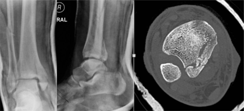
Examples of a Haraguchi II type fracture: anteroposterior, lateral and axial CT cut demonstrating extent of fracture line with articular impaction and loose fragments.
In addition, our understanding of the functional relevance of the PM with respect to the syndesmosis has continued to evolve. We recognize it as the site of primary attachment of the posterior inferior tibiofibular ligament (PITFL), which provides 42% of syndesmotic stability.[8] Fractures of the PM have also shown to result in increased syndesmotic malreduction rates. With loss of the medial buttress of the incisura,[9] the fibula is allowed to externally rotate and slide posteriorly, resulting in malreduction and over-compression at the incisura. PM fixation improves the strength of syndesmotic fixation compared to syndesmosis screws alone.[10] While the improved clinical outcomes have yet to be shown in the literature, it does provide an anatomic argument for direct fixation of these types of fractures.[10]
Access to the PM can be obtained by either a posteromedial or posterolateral approach.[11–13] The decision as to which approach to use is based on several factors, including: apical location of the dominant fracture line, the presence and location of articular impaction and comminution, and associated fractures and injuries. The posterolateral approach is commonly used[14]; however it limits access and fixation to posteromedial fragments. The same argument can be made for the posteromedial approach with respect to limited access to posterolateral fragments. Fixation strategies also vary based on fracture pattern, requiring decisions on screw fixation, posterior buttress plating, or a combination of both. A modified posteromedial approach described by Assal et al[15] allows more lateral access to the posterior tibial malleolus than a standard posteromedial approach. However, what margins can be identified, and how much of the PM can accessed for fixation, have yet to be quantified. The same is true for the posterolateral approach.
Our aims for this biomechanical cadaveric study were twofold: describe the maximal exposure of the PM through both posterolateral and modified posteromedial approaches, and define the maximal screw trajectory obtained through each exposure. We hypothesized that the modified posteromedial exposure would yield greater exposure of the PM and offer a wider range of accessible screw trajectories.
2. Methods
Institutional Research Ethics Board approval was obtained prior to commencing the study. Our methodology was developed as a staged protocol to address the 2 research questions sequentially. Two pilot dissections were performed according to previously described standardized approaches, which subsequently formed the basis for the decision to limit the incisions to 10 cm in length, beyond which further medial–lateral exposure was not obtained at the PM.
2.1. Stage 1: posterior malleolus exposure
Twelve fresh-frozen cadaver limbs were used from 6 cadavers. Limbs were sectioned at mid-thigh to maintain the origin of the gastrocnemius muscle. All limbs were verified free of prior foot and ankle pathology or surgery, and were thawed at room temperature prior to surgical dissection. All dissections were performed by an orthopaedic fellow (BM) or senior resident (JM) under the supervision of the senior surgeon (KAL). Both approaches were performed on each limb. In order to minimize sequencing effects of soft tissue mobilization from the prior exposure and ensure equal numbers in both groups, the specimens were block randomized to 1 of the 2 approaches. The specimens were then subjected to the first surgical approach, surface area mapping, and screw trajectory testing. Only once this was completed was the specimen then subjected to the second surgical approach.
2.2. Posterolateral approach
The posterolateral approach was performed as previously described.[16] The skin incision was marked at the midpoint between the posterior border of the fibula and lateral border of the Achilles tendon, beginning at the level of the distal tip of the fibula. The interval between the peroneal tendons and the flexor hallucis longus (FHL) was bluntly developed. The FHL was then sharply elevated from the posterior border of the fibula and the interval between the FHL, interosseous membrane, and posterior tibia was developed, working lateral to medial. The FHL was retracted using a Hohman retractor to simulate in vivo technique (Fig. 2).
Figure 2.
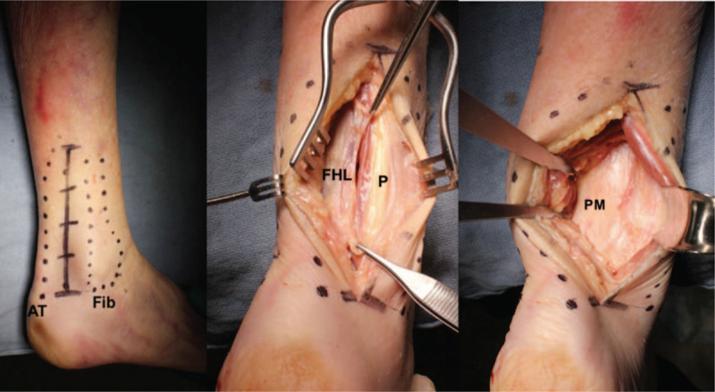
Posterolateral approach exposure. AT = Achilles tendon insertion, Fib = distal fibula, P = peroneal tendons.
2.3. Modified posteromedial approach
The modified posteromedial approach was performed as previously described by Assal et al.[15] The skin incision was marked 1 cm medial to Achilles tendon, extending from the calcaneal insertion proximally for a length of 10 cm. The Achilles tendon was retracted laterally and blunt dissection exposed the transverse intramuscular septum. This was opened sharply to expose the FHL muscle belly. The interval between the FHL and neurovascular bundle was then developed and the FHL was elevated from the posterior tibia using a periosteal elevator. Hohman retractors were then placed over the medial and lateral borders of the tibia to fully expose the PM (Fig. 3).
Figure 3.
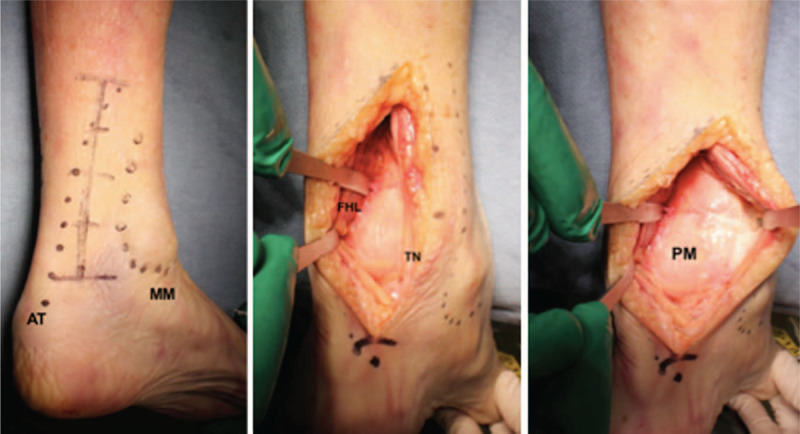
Modified posteromedial approach exposure. AT = Achilles tendon insertion, MM = medial malleolus, TN = tibial nerve.
2.4. Surface area mapping
Following maximal exposure of the PM with each approach, a burr was used to etch the perimeter of visualization. The foot was brought into the full range of both plantar flexion and dorsiflexion to maximize overall exposure prior to etching with the burr.
2.5. Stage 2: posterior-to-anterior screw trajectory
The second stage of the study involved obtaining posterior-to-anterior (P-to-A) screw trajectory at a point 1 cm proximal to the articular surface at the medial and lateral limits. The goal was to identify the maximal medial and lateral trajectory obtainable through each approach. To simulate lag screw conditions with screws perpendicular to fracture planes, all trajectories were obtained with drills perpendicular to the tibial cortex. Therefore, 2 holes were drilled; the first at the maximally obtainable lateral extent, and the second at the maximally obtainable medial extent. Intraoperative conditions were simulated by using a Hohman retractor to reflect the FHL to the far side of the tibia. A long 2.5 mm AO drill-bit with universal drill-guide was used to help prevent soft tissue impingement.
2.6. Screw trajectory assessment
All cadaver legs were assigned a unique identifier to track the order of the surgical approach. CT scans of each leg were obtained to produce 1 mm axial cuts (Aquilion ONE; Toshiba Medical Systems, Tochigi, Japan). Images were reconstructed using OsiriX (Geneva, Switzerland) via a Digital Imaging and Communications in Medicine (DICOM) viewer. We employed the “Cole Mapping Technique” to create overlay images, as previously described for the tibial plafond.[17,18] Axial cuts at the level of the drill holes were transferred to an open source image editor (GimpShop, Tampa, FL) for further analysis
Images were standardized to side, and a grid was overlaid to calibrate sizing and rotation. The fibula and incisura were used as a control for rotation. Overlay images were then created for both the posterolateral approach and the posteromedial approach to allow for the demonstration of range of trajectories for each approach. Screw trajectories were assessed as a percentage of the total width of the PM. The PM was defined as the axial distance from the lateral corner of the posterior tibial tendon groove to the medial extent of the fibular incisura.
2.7. Surface area exposure measurement
Methods for measuring surface area exposure have been previously described and validated.[19] The soft tissues overlaying the ankle were stripped and disarticulated from the ankles for analysis. To quantify the exposed surface area, a laser-and-camera surface scanning system was used to digitize the bones.[20] The distal tibia was mounted within a calibration frame and scanned at multiple angles using a high-intensity linear laser (Fig. 4). The scans from each specimen were referenced to the calibration frame and recorded with a high-resolution video camera. The recordings were then processed into surface maps by triangulating the projection of the laser line on the bone and reference frame with laser-scanning software (DAVID Vision Systems, Koblenz, Germany). The generated surfaces were then overlaid and merged to obtain a complete three-dimensional model with use of the Iterative Closest Point algorithm.[21] This reconstruction technique has been shown to be accurate with a < 0.4 mm RMS (root-mean-square) error.
Figure 4.
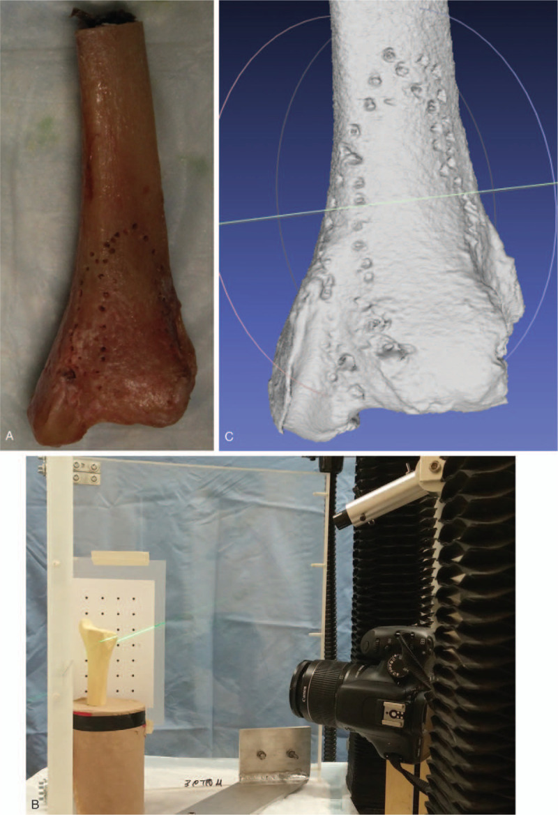
Laser-and-camera surface scanning system setup and imaging: (A) distal tibia stripped of soft tissue with burr etchings outlining each exposure; (B) laser-camera surface-scanning system using saw bone as example; (C) digitalized image of specimen depicted in (A).
To calculate the surface area exposed through each exposure, the total surface area exposed through the combined approaches was first calculated. Then, the surface area of each exposure was calculated and expressed as a percentage of the total.
2.8. Statistical analysis
All measurements were performed by 2 independent assessors at 2 time points; time zero and again at 6 weeks. Intraclass correlation coefficients (ICCs) were calculated to evaluate inter and intra-observer reliability of data measurements. Continuous data were expressed using ratios and percentages. The Kolmogorov–Smirnova test was used to evaluate goodness of fit. Differences between exposures and screw trajectories were evaluated using the Independent Samples t-test for normally distributed data and Mann–Whitney U-test for nonparametric data. Statistical analysis was performed using SAS version 9.4 (SAS Institute, Cary, NC).
3. Results
3.1. Surface area exposed
The absolute percent surface area exposed through each approach is presented in Table 1. The median surface area exposed through the modified posteromedial approach was found to be 99% of total surface area (interquartile range [IQR]: 6%), compared to 64% of total surface area through the posterolateral approach (IQR: 12%). This difference was statistically significant (P < .05) (Fig. 5). The sequence of approaches performed was found to have no significant effect on exposure (P = .69).
Table 1.
Absolute percentages of total exposure area by approach.
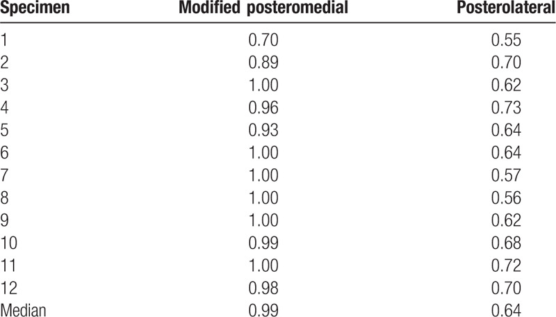
Figure 5.
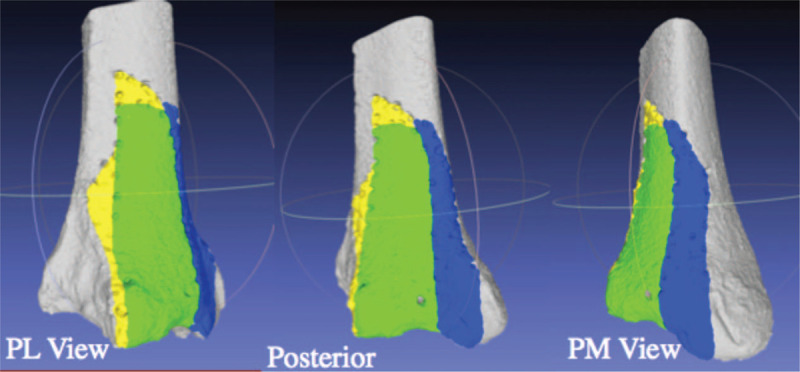
Example of surface area exposed from the posterolateral, direct posterior and posteromedial view. Yellow depicts surface exposed exclusively through the posterolateral approach. Blue depicts surface exposed exclusively through the modified posteromedial approach. Green depicts surface exposed through both approaches. This example is from specimen 2.
3.2. Screw trajectories
Assessment of screw trajectories obtainable through each exposure showed it was possible to place a screw perpendicular to the tibia a median of 77% across the PM through the modified posteromedial approach (range 70%–100%), and a median of 46% across the PM through the posterolateral approach (range 34–60%). This difference was found to be statistically significant (P < .05) (Fig. 6). The sequence of approaches performed was found to have no significant effect on screw trajectory (P = .22).
Figure 6.
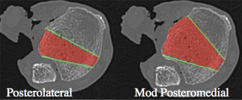
Averaging of perpendicular screw trajectories obtained through the posterolateral and modified posteromedial approaches.
3.3. Reliability of assessments
For surface area measurements, the ICC for inter-rater and intrarater agreements were strong for both the modified posteromedial and posterolateral exposures (alpha: 0.89; alpha: 0.86, respectively). For screw trajectory assessment, the ICC for inter-rater agreement and intrarater agreement was also strong (alpha: 0.98; alpha: 0.92, respectively).
4. Discussion
Several surgical strategies have been suggested for addressing PM fractures. While type 1 fractures can easily be addressed through a standard posterolateral approach, the strategy is less clear for type 2 fractures. Posterolateral, posteromedial, and dual posterolateral and posteromedial approaches have all been suggested based on surgeon comfort and experience.[14,22] Assal et al[15] described a modified posteromedial approach, working through the interval of the FHL and neurovascular bundle, and advocated its use as a universal access interval to the PM. Consequently, we sought to identify both the exposure area obtainable through this approach when compared to the posterolateral approach, and the ability to instrument the PM using lag-screw principles through both approaches.
Haraguchi type 2 fractures are of particular interest as they often present as 2 separate fracture fragments sharing a common fracture line. This pattern is commonly seen in a hyperplantarflexion ankle fracture variant. The lateral component contains the PITFL, whereas the medial fragment extends to the posterior colliculus of the medial malleolus and contains the insertion to the deep deltoid ligament.[23] With both structures disrupted, the ankle is inherently unstable. This has led to posterior malleolar fractures being compared to coronoid fractures as classified by O’Driscoll,[18,24] where the fracture morphology may be more relevant than fragment size.
Our results clearly demonstrate that the modified posteromedial approach allows for both significantly more exposure of the PM, permits more posteromedial access, and provides very similar posterolateral access when compared to the posterolateral approach. These results are in keeping with another recent anatomic study by Assal et al[25] that compared exposure area through the posterolateral, posteromedial and modified posteromedial approaches. This study also demonstrates that the modified posteromedial approach provides significantly more access for instrumentation compared to the posterolateral approach—a practical application not addressed in the aforementioned study.
We anticipate that our findings are most generalizable to the surgeon faced with a Haraguchi type 2 fracture, but can be extrapolated to all posterior malleolar fractures and posterior pilon variants. Our standard practice, with the patient in the prone position, is to start with a modified posteromedial approach to reduce and fix the posterior tibia. The fibula is then addressed through a separate lateral incision, and the medial malleolus through a small anteromedial approach when required. This incision orientation maximizes respect for the angiosomes around the ankle,[26] while not compromising fracture visualization.
We acknowledge that as with any cadaveric study, there are some inherent limitations. The clinical implications and risks of the surgical approaches cannot be inferred. We do advise caution with the modified posteromedial approach with respect to avoiding vigorous medial retraction on the neurovascular bundle. Our experience, albeit rare, is that tibial nerve irritation or neuropraxia is possible following this approach. However, traction on the neurovascular bundle was recently investigated using the posterolateral, posteromedial and modified posteromedial approaches using a strain gauge, and found to be lowest in the posteromedial approach group.[25] Additionally, all dissections were performed mounted in the prone position, so any exposure differences due to positioning cannot be accounted for. This is particularly relevant for the assessment of screw trajectories, which may be affected by the logistics of drill positioning with the patient in the lateral decubitus or supine positions. Similarly, while we did randomize the order of dissection on each limb, we cannot account for individual size difference and muscle density that could alter exposure area. Finally, while we did attempt to best simulate lag screw technique, we acknowledge that further screw trajectories and hardware placement may be obtainable beyond our testing conditions.
Overall, our study demonstrated that the modified posteromedial approach allows for significantly greater access to the PM, and can facilitate instrumentation of this difficult to access region. As such, while we are strong advocates for its utility when approaching Haraguchi type 2 fractures, it is more of a utilitarian type of approach to the posterior distal tibia. Further clinical studies should be performed to address patient outcomes and complications when using this surgical approach.
References
- 1.Gardner MJ, Streubel PN, McCormick JJ, et al. Surgeon practices regarding operative treatment of posterior malleolus fractures. Foot Ankle Int. 2011;32:385–393. [DOI] [PubMed] [Google Scholar]
- 2.Haraguchi N, Haruyama H, Toga H, et al. Pathoanatomy of posterior malleolar fractures of the ankle. J Bone Joint Surg Am. 2006;88:1085–1092. [DOI] [PubMed] [Google Scholar]
- 3.Assal M, Ray A, Fasel JHD, et al. A modified posteromedial approach combined with extensile anterior for the treatment of complex tibial pilon fractures (AO/OTA 43-C). J Orthop Trauma. 2014;28:e138–e145. [DOI] [PubMed] [Google Scholar]
- 4.Irwin TA, Lien J, Kadakia AR. Posterior malleolus fracture. J Am Acad Orthop Surg. 2013;21:32–40. [DOI] [PubMed] [Google Scholar]
- 5.Tornetta P, Ricci W, Nork S, et al. The posterolateral approach to the tibia for displaced posterior malleolar injuries. J Orthop Trauma. 2011;25:123–126. [DOI] [PubMed] [Google Scholar]
- 6.Macko VW, Matthews LS, Zwirkoski P, et al. The joint-contact area of the ankle. The contribution of the posterior malleolus. J Bone Joint Surg Am. 1991;73:347–351. [PubMed] [Google Scholar]
- 7.Hartford JM, Gorczyca JT, McNamara JL, et al. Tibiotalar contact area. Contribution of posterior malleolus and deltoid ligament. Clin Orthop Relat Res. 1995;320:182–187. [PubMed] [Google Scholar]
- 8.Fitzpatrick DC, Otto JK, McKinley TO, et al. Kinematic and contact stress analysis of posterior malleolus fractures of the ankle. J Orthop Trauma. 2004;18:271–278. [DOI] [PubMed] [Google Scholar]
- 9.Ferries JS, DeCoster TA, Firoozbakhsh KK, et al. Plain radiographic interpretation in trimalleolar ankle fractures poorly assesses posterior fragment size. J Orthop Trauma. 1994;8:328–331. [DOI] [PubMed] [Google Scholar]
- 10.Cole PA, Mehrle RK, Bhandari M, et al. The pilon map: fracture lines and comminution zones in OTA/AO type 43C3 pilon fractures. J Orthop Trauma. 2013;27:e152–e156. [DOI] [PubMed] [Google Scholar]
- 11.Mangnus L, Meijer DT, Stufkens SA, et al. Posterior malleolar fracture patterns. J Orthop Trauma. 2015;29:428–435. [DOI] [PubMed] [Google Scholar]
- 12.Büchler L, Tannast M, Bonel HM, et al. Reliability of radiologic assessment of the fracture anatomy at the posterior tibial plafond in malleolar fractures. J Orthop Trauma. 2009;23:208–212. [DOI] [PubMed] [Google Scholar]
- 13.Desloges W, Louati H, Papp SR, et al. Objective analysis of lateral elbow exposure with the extensor digitorum communis split compared with the kocher interval. J Bone Joint Surg Am. 2014;96:387. [DOI] [PubMed] [Google Scholar]
- 14.Ogilvie-Harris DJ, Reed SC, Hedman TP. Disruption of the ankle syndesmosis: biomechanical study of the ligamentous restraints. YJARS. 1994;10:558–560. [DOI] [PubMed] [Google Scholar]
- 15.Werner S, Neumann I, Thienel KC, et al. A fractal-based approach for the determination of concrete surfaces using laser scanning techniques: a comparison of two different measuring systems. Mater Struct. 2013;46:245–254. [Google Scholar]
- 16.Cherney SM, Haynes JA, Spraggs-Hughes AG, et al. In vivo syndesmotic overcompression after fixation of ankle fractures with a syndesmotic injury. J Orthop Trauma. 2015;29:414–419. [DOI] [PMC free article] [PubMed] [Google Scholar]
- 17.Besl PJ, McKay ND. Method for registration of 3-D shapes. IEEE Transactions on Pattern Analysis and Machine Intelligence. 1992;2:239–256. [Google Scholar]
- 18.Gardner MJ, Brodsky A, Briggs SM, et al. Fixation of posterior malleolar fractures provides greater syndesmotic stability. Clin Orthop Relat Res. 2006;447:165–171. [DOI] [PubMed] [Google Scholar]
- 19.Hinds RM, Tran WH, Lorich DG. Maisonneuve-hyperplantarflexion variant ankle fracture. Orthopedics. 2014;37:e1040–e1044. [DOI] [PubMed] [Google Scholar]
- 20.Amorosa LF, Brown GD, Greisberg J. A surgical approach to posterior pilon fractures. J Orthop Trauma. 2010;24:188–193. [DOI] [PubMed] [Google Scholar]
- 21.Bois AJ, Dust W. Posterior fracture dislocation of the ankle: technique and clinical experience using a posteromedial surgical approach. J Orthop Trauma. 2008;22:629–636. [DOI] [PubMed] [Google Scholar]
- 22.Assal M, Ray A, Stern R. Strategies for surgical approaches in open reduction internal fixation of pilon fractures. J Orthop Trauma. 2015;29:69–79. [DOI] [PubMed] [Google Scholar]
- 23.Hinds RM, Garner MR, Lazaro LE, et al. Ankle fracture spur sign is pathognomonic for a variant ankle fracture. Foot Ankle Int. 2015;36:159–164. [DOI] [PubMed] [Google Scholar]
- 24.O’Driscoll SW, Jupiter JB, Cohen MS, et al. Difficult elbow fractures: pearls and pitfalls. Instr Course Lect. 2003;52:113–134. [PubMed] [Google Scholar]
- 25.Assal M, Dalmau-Pastor M, Ray A, et al. How to get to the distal posterior tibial malleolus? A cadaveric anatomic study defining the access corridors through 3 different approaches. J Orthop Trauma. 2017;31:e127–e129. [DOI] [PubMed] [Google Scholar]
- 26.Taylor GI, Palmer JH. The vascular territories (angiosomes) of the body: experimental study and clinical applications. Br J Plast Surg. 1987;40:113–141. [DOI] [PubMed] [Google Scholar]


