Abstract
In 1967, a diamond polymorph was reported from hard, diamond-like grains of the Canyon Diablo iron meteorite and named lonsdaleite. This mineral was defined and identified by powder X-ray diffraction (XRD) features that were indexed with a hexagonal unit cell. Since 1967, several natural and synthetic diamond-like materials with XRD data matching lonsdaleite have been reported and the name lonsdaleite was used interchangeably with hexagonal diamond. Its hexagonal structure was speculated to lead to physical properties superior to cubic diamond, and as such has stimulated attempts to synthesize lonsdaleite. Despite numerous reports, several recent studies have provided alternative explanations for the XRD, transmission electron microscopy and Raman data used to identify lonsdaleite. Here, we show that lonsdaleite from the Canyon Diablo diamond-like grains are a nanocomposite material dominated by subnanometre-scale cubic/hexagonal stacking disordered diamond and diaphite domains. These nanostructured elements are intimately intergrown, giving rise to structural features erroneously associated with h diamond. Our data suggest that the diffuse scattering in XRD and the hexagonal features in transmission electron microscopy images reported from various natural and laboratory-prepared samples that were previously used for lonsdaleite identification, in fact arise from cubic/hexagonal stacking disordered diamond and diaphite domains.
This article is part of the theme issue 'Exploring the length scales, timescales and chemistry of challenging materials (Part 2)'.
Keywords: lonsdaleite, hexagonal diamond, nanocomposite, diaphite, structural complexity
1. Introduction
Between 1967 and 1968, hexagonal (h) diamond was described from laboratory samples [1,2], from the Canyon Diablo and Goalpara meteorites [3] and as the newly named mineral lonsdaleite from the Canyon Diablo iron meteorite [4]. Bundy & Kasper [1] and Cowan et al. [2] reported the structure of h diamond from Debye–Scherrer patterns from diffraction lines that could be indexed with a hexagonal unit cell with a = 2.52 Å, c = 4.12 Å and space group P63/mmc. X-ray reflections that matched those expected for h diamond described in [1] and [2] were used to identify this phase in hard, diamond-like grains from the Canyon Diablo iron meteorite [3]. Lonsdaleite, which is the name given to the h diamond component from hard carbon grains in the Canyon Diablo iron meteorite [4], was similarly described from X-ray diffraction (XRD) data that was ‘identical in appearance with that of the wurtzite 2H polymorph of zinc sulfide, apart from differences in the spacings appropriate to the unlike cell sizes, and were completely indexed in terms of a hexagonal cell’ [4]. Thus, these early reports are consistent with lonsdaleite, named after the pioneering crystallographer Prof. Dame Kathleen Lonsdale, as the mineral analogue of h diamond.1
These early reports describe h diamond and lonsdaleite based on XRD data from Laue and Debye–Scherrer photographs. However, the raw XRD images are not available and these reports, except [3], only show tables of observed d spacings, which suggest a good match with h diamond, but hide any complexity that may have been observed in the diffraction patterns. However, these authors also indicate that their XRD data did not match pure h diamond. Frondel & Marvin [4] annotated the XRD intensities by writing ‘visual estimate of mixture with diamond’, and mentioned in the figure caption of the photo of the grains ‘cubes consisting of diamond and lonsdaleite.’ Hannemann et al. [3], Bundy & Kasper [1] and Cowan et al. [2] listed the d spacings of h diamond that overlapped with c diamond. Hanneman et al. [3] reported the XRD study of three Canyon Diablo grains, and estimated that they contain at most 30% h diamond. Thus, even the original specimens used to define lonsdaleite were described as mixtures of cubic (c) and h diamond.
Several natural and synthetic materials with diffraction data matching lonsdaleite have subsequently been reported and the name lonsdaleite is interchangeably used with h diamond. For example, it was described from meteorites [6–10], impact structures [11–13] and terrestrial sediments [14]. Its formation has been associated with high-pressure (HP) and high-temperature (HT) shock processes and its occurrence was used as evidence of asteroidal impacts, both extraterrestrial and on Earth [3,6–10]. In addition to shock formation, lonsdaleite has been reported from ultrahigh-pressure metamorphic rocks of the Kumdykol diamond deposit [15]. Its formation was assigned to conditions near 18 GPa and 1400 K [16] and it has also been reported to form from the shock compression of graphite between 20 and 200 GPa [2,17–19]. Several studies suggest an orientational relationship between graphite, lonsdaleite and c diamond [1,20–22], and it was argued to play an important role during the martensitic graphite to c diamond transition [17,21].
Early reports and numerous subsequent ones used XRD data for the identification of h diamond. A characteristic feature of the X-ray data from both laboratory-produced and terrestrial/extraterrestrial samples interpreted as h diamond/lonsdaleite are broad diffraction features. The broadness of the XRD reflections, as well as the fact that the most intense c diamond reflections coincide with the purported h diamond reflections, complicates the analysis of the patterns. As a result, the majority of the XRD data were interpreted as physical mixtures of c and h diamond, and the significant broadening was attributed to small particle sizes [3,4,23]. Even the early reports [3,4] suggested that the particle size of Canyon Diablo h diamond was below a few tens of nanometres. Similarly, Yoshiasa et al. [23] used Rietveld refinements for analysing the XRD data of HP and HT compressed graphite samples and determined a small (approx. 1 nm) crystallite size of h and c diamonds.
Given the apparent nanometre scale of the diffracting domains, transmission electron microscopy (TEM) has been used to probe the structure of samples that are thought to contain lonsdaleite [24–31]. In particular, selected-area electron diffraction (SAED) patterns and fast Fourier transforms (FFTs) calculated from high-resolution TEM (HRTEM) images have been used to report h diamond (Supplementary Materials in [31]). However, analogous to the XRD patterns, the electron diffraction patterns show broadening and streaking of the diffraction spots. Concerns have been raised against the h diamond identifications because its diagnostic reflections have not been observed, and the streaking of reflections can be explained from stacking disorder [24–26,31,32]. Furthermore, several studies suggest that the hexagonally arranged hki0 reflections are not diagnostic for h diamond and thus should not be used for its identification [24–32].
Insight into the atomic-scale structure of the Canyon Diablo hard carbon grains is provided by aberration-corrected HRTEM [24,31]. Several recent papers demonstrate that these samples, which were originally used to identify and define lonsdaleite, are dominated by nanometre-scale structural complexity [24,27–31]. In particular, distinct nanometre-sized h diamond domains are absent. Instead, the TEM data show that the grains are composed of an intimate mixture of c diamond twins and stacking faults together with diamond–graphite nanocomposites containing sp3-/sp2-bonded structures, called diaphites [27–31]. Two distinct diaphite structures were reported based on HRTEM observations combined with density functional theory (DFT) calculations. Type 1 and type 2 diaphite structures are characterized by few-layered sp2-bonded graphene layers inserted between {111} surfaces of c diamond and by the coherent bonding of graphene layers with the {113} c diamond surfaces, respectively. For both types the numbers of graphitic and diamond layers are variable. Thus, understanding the structural complexity of the Canyon Diablo hard carbon requires the consideration of c and h diamond stacking and associated diaphite structures.
The HRTEM data show the dominance of stacking disorder in the Canyon Diablo hard carbon grains [24,31]. As such, it is inappropriate to model the powder XRD patterns from these grains purely as a physical mixture of nano-sized h and c diamonds. In addition, such a simplistic modelling does not capture the structural complexity revealed by TEM, including the diaphite structures. Quantitative analysis of the stacking disorder is provided by the DIFFaX analysis method [33], which calculates powder patterns of layered structures with stacking disorder. The input data are the lattice constants, atomic coordinates within the layers, symmetry relationships between the layers for the different types of stacking, peak profile parameters, thermal displacement parameters and stacking probabilities. Recently, DIFFaX was extended by implementing a least-squares refinement of the various parameters [34,35]. The new approach permits Monte Carlo-type random changes of the various parameters in order to find the best fit to the diffraction data and to enable the fitting procedure to avoid local minima. This new approach, called MCDIFFaX, was applied to powder XRD data acquired from a range of samples purported to contain h diamond [26,31,35,36] as well as ice [34], silver iodide [37] and ammonium fluoride [38]. With MCDIFFaX, the XRD data can be modelled in terms of the hexagonality Φh parameter, which reflects the fraction of hexagonal stacking events. Accordingly, the cubicity, Φc, reflecting the fraction of cubic stacking, is given by 1 − Φh. MCDIFFaX can consider up to second-order stacking probabilities, which means that independent stacking probabilities can be defined that depend on up to two previous stacking events. For example, Φccc is a second-order stacking probability that reflects the probability of cubic stacking following two previous cubic stacking events. Both hexagonality and cubicity can be calculated from the higher order stacking probabilities [35]. It is informative to plot the first-order stacking probabilities, Φhc and Φcc, on a ‘stackogram’, where the overall hexagonality can be read off as well as information on the tendencies for either switching or staying with the same type of stacking. The application of the MCDIFFaX method to powder XRD profiles of a range of h diamond/lonsdaleite bearing samples shows that they are dominated by stacking disordered diamond, and none display a hexagonality greater than 0.6 [35].
In this contribution, we investigate the structure of the Canyon Diablo hard carbon grains from the Buseck Center for Meteorite Studies (BCMS), Arizona State University (ASU). These grains are characterized by their extreme resistance to mechanical abrasion and chemical treatment. We refer to these grains as cotype specimens although in the strict sense only the samples investigated by Frondel & Marvin [4] should be referred to as such [39]. However, our description is justified since (i) the first reports were based on materials selected from the Canyon Diablo meteorite collection of BCMS (formerly the Center for Meteorite Studies—CMS) by founding director Prof. Carleton Moore, (ii) all the Canyon Diablo hard carbon grains have similar physical appearances and display the matching characteristic structural features used for lonsdaleite identification and (iii) neither of the original specimens used for analysis correspond to pure phase lonsdaleite. We examine the X-ray and electron diffraction features of h diamond and compare it with c/h stacking disordered diamond, graphite and diaphite. We point out the problems of the XRD peak assignments with physical mixtures of c and h diamonds, reveal the diagnostic electron diffraction data of h diamond, and emphasize that the hexagonal features on TEM images are not unique for h diamond. Microfocus synchrotron XRD combined with MCDIFFaX modelling and HRTEM images demonstrate the combination of various intergrowth types among c/h stacking disordered diamond and diaphite as well as provide an explanation for the structural complexity of the Canyon Diablo specimens and other samples previously described as lonsdaleite.
2. Experimental procedure
(a) . Samples, XRD measurements and analysis, calculation of ED data and TEM measurements and data processing
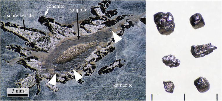
Hard carbon grains were extracted from the Canyon Diablo iron meteorite following the procedure described in [24,40]. The grains are black with an adamantine luster (figure 1), their sizes range from tens of micrometres to millimetres, and they showed extreme resistance to mechanical abrasion. Hard carbon grains were extracted from two shocked graphite nodules (ASU#34_140, ASU#34_141) and from a shocked graphite–troilite region in sample ASU#34_SH.
Figure 1.
Photograph of a section of Canyon Diablo iron meteorite slice (left) containing hard carbon grains (formerly called diamonds) and a selection of grains extracted after acid dissolution and heavy density mineral separation (right). The iron was ground, polished and etched with nital and shows the characteristic mineralogy of a hard carbon-grain-bearing region. The hard carbon grains (indicated by the white arrows), which sit proud of the surface, occur within the graphite rim surrounding the crystalline troilite core. The iron meteorite slice is sample #34.102x in the Buseck Center for Meteorite Studies and is the mirror slice of the sample studied by Ksanda and Henderson in 1939 [41]. Scale bars next to the extracted hard carbon grains = 1 mm.
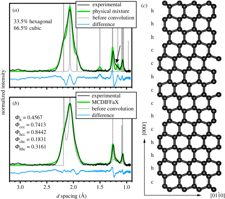
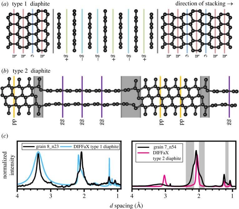
The XRD data shown in figure 2 were obtained following the measurement protocol reported in [24] from a hard carbon grain using a Bruker SMART APEX single-crystal diffractometer employing MoKα radiation (λ = 0.71073 Å). The XRD datasets shown in figure 3 were obtained following the measurement protocol reported in [31] from two hard carbon grains (called grain 7 and 8) using a 2 × 2 µm X-ray beam (λ = 0.3738 Å) at the ID27 beamline of the ESRF-EBS synchrotron facility in Grenoble, France. Figure 3b,c correspond to the integrated profiles of the n23 and n54 two-dimensional maps from grain 8 and grain 7 shown in [31]. The data in figure 2b,c were analysed using a physical mixture of c and h diamond crystallites and the MCDIFFaX protocol based on models built for sp3-bonded c/h stacking disorder [35]. The diffraction patterns in figure 3b,c were investigated using the DIFFaX protocol based on models built for type 1 and type 2 diaphite structures, respectively. Details of the fitting procedure of c/h stacking disordered diamond, type 1 and type 2 diaphites were presented in [26,27,31,35,36].
Figure 2.
XRD data of an approximately 0.1 mm-size hard carbon grain, reported in [24], analysed (a) as a physical mixture of c and h diamond structures and (b) with c/h stacking disorder using MCDIFFaX. (c) Example structure of c/h stacking disordered diamond projected along . Hexagonal and cubic stacking are indicated by ‘h’ and ‘c’, respectively.
Figure 3.
Structure model of type 1 and type 2 diaphite structures and their corresponding simulated XRD patterns plotted on XRD data measured from 2.0 × 2.0 µm−2 areas of two Canyon Diablo grains referred to as grain 8 and grain 7 in [31]. (a) For type 1 diaphite graphene layers with ‘g+’ and ‘g−’ type stackings are inserted within c/h stacking disordered diamond. (b) For type 2 diaphite the ‘dd’ and ‘gg’ indicate the continuations of cubic diamond and graphene regions, respectively, whereas the grey-shaded areas show the structures required to transition from cubic diamond to graphene and vice versa. (c) The simulated patterns of type 1 (Φc = Φh = 0.4, Φdg = Φgd = 0.2, Φg+ = Φg− = 0.4) and type 2 diaphite (Φgg = 0.9, Φdg = 0.0053, Φg = 0.1) obtained by DIFFaX analysis are shown in blue and pink, respectively, on the measured XRD patterns.
Electron diffraction patterns were calculated using the Single Crystal software (CrystalMaker Software Ltd., Oxford, UK) for a thickness of 10 nm using the structures for c diamond, h diamond, c/h stacking disordered diamond and 2H graphite (figure 3). For the c/h stacking disordered diamond a CIF file of a stacking disordered structure with Φh = 0.5, random stacking and 120 layers was prepared with the STACKY program as described in [42]. Due to multiple scattering of electrons, only the arrangements and d spacings of the reflections should be compared with experimental data. The Single Crystal software does not show the 200 reflection of c diamond along even for 100 nm thick samples. This reflection should not occur due to the systematic absence of the d glide. However, Cowley et al. [43] demonstrated that this reflection has appreciable intensity for samples thicker than 5 nm based on multi-slice electron diffraction calculations and we observed it even from 2 to 4 nm thick nanodiamonds [25]. Therefore, we presume the Single Crystal software does not calculate properly the dynamically scattered electrons, and we included the 200 reflection for the c diamond calculated electron diffraction patterns.
For the TEM investigations, hard carbon grains were crushed with a pestle and mortar, suspended in distilled water and dried on lacy-C-coated Cu TEM grid. From grain 7 (reported in [31]) two lamellae, perpendicular to each other and measuring 10 × 2 µm in area and approximately 40–50 nm thickness, were cut and focus ion-beam (FIB) thinned using a Thermo Scientific Scios 2 Dual Beam equipment. The crushed grains were investigated using a JEOL JEM 4000EX (400 kV; 0.17 nm point resolution) (figure 5a) and an aberration-corrected JEOL ARM200F scanning (200 keV, 0.08 nm point resolution) (figures 5b, 6a,c, 7a,b, 8a,b, 10a,c) transmission electron microscope. The FIB lamellae were studied using a Philips CM 20 (200 keV, 0.25 nm point resolution) (SAED patterns of figure 5c,d) and an aberration-corrected Thermo Fisher Scientific FEI THEMIS 200 microscope (200 keV, 0.07 nm point resolution) (figures 5c,d, 8d, 9a, 10d). FFTs were calculated using Gatan Digital Micrograph v. 3.6.1 software. Note, we use four indices hkil (i = −(h + k)) for labelling diffraction spots, crystallographic planes and directions of h diamond, c/h stacking disordered diamond and graphite.
Figure 5.
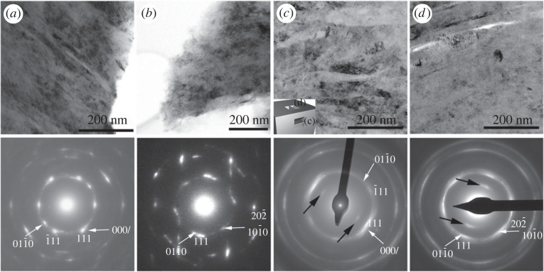
Low-magnification TEM images and corresponding SAED patterns taken from crushed grains (a,b) and FIB lamellae (c,d) of Canyon Diablo hard grains. Small inset in (c) shows the orientation of the FIB samples. The reflections spread over a large area roughly correspond to d spacings of 2.2 and 1.8 Å. The SAED patterns are indexed as (a,c) and (b,d) c diamond. White arrows mark indices for (a,c) and (b,d) c/h stacking disordered diamond. Vertical streaks on the SAED pattern (b) indicate (000l) c/h stacking disorder, i.e. the imaged area contains and projected c/h stacking disordered diamond domains. Black arrows in (c) and (d) point to graphite 000l reflections. Original BFTEM images and SAED patterns of (c) and (d) were reported in [31] (copyright, PNAS).
Figure 6.
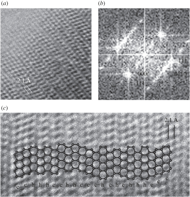
HRTEM image of c/h stacking disordered diamond (a), with corresponding FFT indexed as c diamond and c/h stacking disordered diamond (b), and its structure model plotted on an HRTEM image (c). Original HRTEM image (a) was reported in [24], copyright Springer Nature Ltd.
Figure 7.
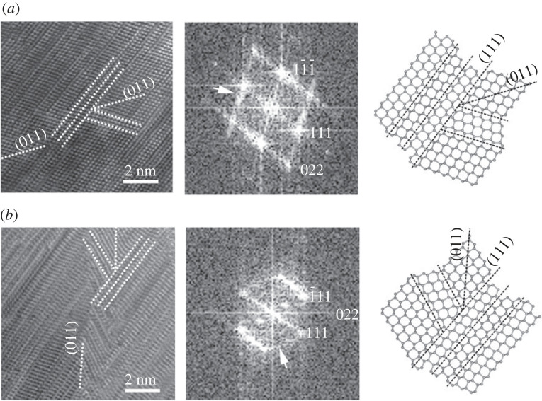
Complex (011) twins (a,b) with corresponding FFTs, and their structure models. The indices refer to c diamond structure. White arrows on the FFTs (a,b) mark a second set of streaking that resulted from the (011) twins. Original HRTEM images (a) were reported in [24], copyright Springer Nature Ltd.
Figure 8.
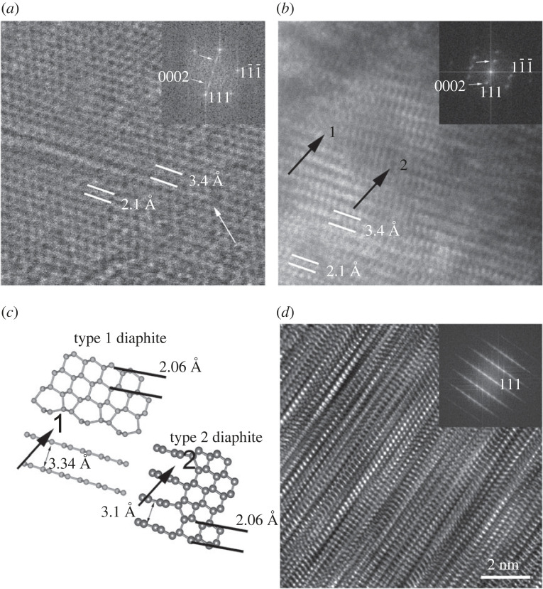
HRTEM images of type 1 and type 2 diaphite structures viewed along c diamond and their corresponding FFTs. Type 1 and type 2 diaphite intergrowth (a,b) and their corresponding structure model (c). Vertically superimposed diaphite and c/h stacking disordered diamond structures give rise to complexity for an approximately 50–60 nm thick sample (d).
Figure 10.
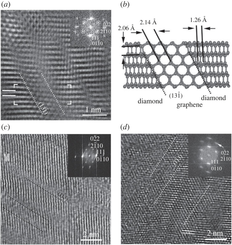
Type 2 diaphite viewed along c diamond and graphene. The original HRTEM image of (a) and the structure model (b) are reported in [24] (copyright Springer Nature Ltd.) and [27] (copyright ACS). White circles in (a) mark hexagonally arranged reflections and the dotted lines indicate the interface between c diamond and graphene. Type 2 diaphite examples with variable c diamond and graphene contents (c). Black dotted lines mark the interface between c diamond and (0001) graphene. The c diamond contribution is evidenced by the elongation of the domains (white dotted lines) and the streaking of reflections is marked by a white arrow (d) in a 50–70 nm thick sample.
Figure 9.
uHRTEM image (a) and its corresponding FFT (b) show evidence for c diamond and c/h stacking disordered diamond intergrowth. White arrow marks in (b) split reflections with an approximately 10° rotation.
3. Results and discussion
(a) . Morphological characteristics of the hard carbon grains from Canyon Diablo
The hard carbon grains occur in shocked-transformed metal and shocked graphite nodules from the Canyon Diablo iron meteorite (figure 1). Their presence is evident during the cutting of the iron meteorites as the diamond saw blades only penetrate the regions with the hard carbon grains with extreme difficulty. These grains also protrude from the cut surfaces after grinding and polishing with SiC impregnated papers (figure 1). These hard grains are extracted by dissolving the enclosing metal as well as associated troilite with hot concentrated HNO3 leaving a granular black residue. Residual schreibersite was removed with a magnet. This residue is washed, dried and further separated using lithium metatungstate heavy liquid with a density of approximately 3 g cm−3. The high-density residue is dominated by black grains with an adamantine lustre (figure 1). Most grains are anhedral, with a crude layered structure. A small subset of the grains has a cubic morphology, presumably reflecting their formation from cliftonite, which are aggregates of graphite particles with cuboid morphology [5,44], present in the metal prior to the impact shock event on Earth. The hard carbon grains, also often called diamond, were first described from the Canyon Diablo iron meteorite in the nineteenth century [5,45], and subsequently received considerable attention, especially during the mid-twentieth century [3,4,46–49]. The meteorites with the hard carbon grains are primarily found in specimens collected from the rim of the crater [50–53], consistent with their formation from the shock wave generated by the impact of the main iron mass that formed the crater.
(b) . XRD features of c/h stacking disordered diamond
The XRD data from a single, cubic, approximately 0.1 mm hard carbon grain displays broad diffraction features including those that arise from c diamond as well as poorly resolved maxima on the ‘shoulders’ of these broad features at 2.18, 1.93 and 1.16 Å that can be indexed using the unit cell of h diamond (figure 2a,b). The relative intensities of these diffraction features match those reported for the material used for h diamond/lonsdaleite identification [2–4]. However, the 1.51 Å XRD feature, corresponding to the d spacing of the h diamond, is missing. Synchrotron microbeam XRD maps obtained from 2.0 × 2.0 µm−2 areas of Canyon Diablo hard grains reveal their heterogeneous nanocomposite structure [31]. These patterns are characterized by diffuse and continuous rings. The high intensity of the broad rings extends across several pixels of the detector and the highest intensity features are often arranged to display a hexagonal pattern [31]. The major rings are centred at 3.34 (reduced to 3.1 Å in some areas), 2.06, 1.25 and 1.05 Å spacings, though the first ring is absent from some areas [31]. The circular integration of the wide rings from the two-dimensional dataset results in a one-dimensional pattern that shows broad XRD peaks with ‘asymmetric tails’, attributed to diffuse scattering contributions.
In stacking disordered materials, translational symmetry is maintained within the layers, yet is broken in the direction of stacking. Hence, the l Miller index of the Bragg peaks affected by the stacking disorder is no longer restricted to integer numbers and can take continuous values. This results in ‘streaking’ in reciprocal space that manifests itself after integration in a one-dimensional XRD pattern, as broad and asymmetric features. Figure 2c shows a possible structure of c/h stacking disordered diamond where cubic and hexagonal stacking is indicated by ‘c’ and ‘h’, respectively. In principle, any stacking sequence is possible including the aforementioned memory effects that define the preference for certain long-range stacking motifs. As shown in figure 2a,b, all diffraction features are broad resulting from small diffracting domains. This means that the asymmetric diffuse scattering from the stacking disorder is not easily detectable without detailed analysis. Figure 2a shows a standard Rietveld fit using a physical mixture of pure c and pure h diamond with variable phase fraction. The dotted grey and solid green lines show the simulated diffraction data before and after the convolution with a Pseudo-Voigt profile function, respectively. The physical mixture structural model shows significant deficiencies with respect to reproducing the experimental diffraction data shown in black. In particular, the shape of the main feature at approximately 2.1 Å is not well reproduced including the two shoulders; the intensity of the approximately 1.5 Å feature, which is absent in the experimental data, is overestimated and the asymmetric diffuse scattering at approximately 1.2 Å is not reproduced (highlighted with an arrow). Overall, this modelling illustrates that a physical mixture of pure c and pure h diamond does not adequately reproduce the experimental diffraction data.
By contrast, figure 2b shows an MCDIFFaX fit to the experimental diffraction allowing second-order stacking probabilities. Again, the data before the convolution with the profile function are shown in grey. In addition to sharp Bragg features, MCDIFFaX produces the diffuse asymmetric scattering arising from the stacking disorder at approximately 2.0 and 1.2 Å. After convolution with the profile function, a very good fit to the experimental data is observed. The MCDIFFaX analysis reproduces the overall shape of the main feature, does not show the occurrence of the experimentally not observed approximately 1.5 Å XRD feature and produces the diffuse asymmetric scattering at approximately 1.2 Å. The refined second-order stacking probabilities are given in figure 2b that result in a hexagonality of 0.4567, i.e. 45.67% hexagonal and 54.33% cubic stacking within this sample. We note that this number gives the amounts of hexagonal layer stackings, and it does not mean the sample contains 45.67% h diamonds. The corresponding first-order stacking probabilities Φcc and Φhc are 0.7655 and 0.2790, respectively. Since Φcc > Φc and Φhc < Φc means that the sample displays a preference for staying within either a cubic or hexagonal stacking sequence rather than random stacking or even preferential switching between h and c. Yet it is still sufficiently distinct from a physical mixture with essentially infinitely long cubic and hexagonal sequences. An example stacking sequence consistent with the refined second-order stacking probabilities is
hchhccchhccchhhhccchhchhchhhhhhhcchccccccchhhhhcchhhhhhcccchhhhcccccccccccchhhchcccccchhhhcccccchcccchhcchhhcchhhhhhhhhcccccccccchccchhhcccccchhhhccchhcchhhhccccccccchhhhhhhhhhcccchchhhcccccccchhhhcccccccchhhccchhccccccchhhhhccchhhhhhhhhccccchhhcchcchhhhhcccccchhhhhhcchhhhhccccchhhhccccchhcccchhhcc.
(c) . XRD features of diaphite
The structures of the two different types of diaphite are shown in figure 3a,b. For the DIFFaX models, some simplifications were made. For type 1 diaphite, the diamond regions were allowed to display c/h stacking and depending on the shifts upon stacking the graphene sheets, i.e. either g+ or g−, hexagonal and rhombohedral stacking can be achieved. Yet, no structural reconstructions were implemented at the interfaces between diamond and the stacked graphenes [31]. Type 2 was considerably more difficult to implement in DIFFaX since transition motifs between diamond and graphene regions are needed. These are shown with grey shading in figure 3b. As a consequence of this, it was difficult to additionally implement the c/h stacking disorder in the diamond regions. The lengths of the diamond and graphene regions are determined by the probabilities associated with the dd and gg stacking events [31].
Many XRD patterns of Canyon Diablo show an intense but broad reflection at d = 3.34 Å, corresponding to the interlayer spacings of graphene sheets in graphite and in type 1 diaphite (figure 3a). Although this broad reflection can be explained with fine-grained (1–5 nm size) graphite, this peak can also arise from type 1 diaphite since TEM investigation of the samples indicates the abundance of crystallographically intergrown graphene and c diamond layers [31]. Several of the XRD patterns display a broad maximum at 3.1 Å consistent with type 2 diaphite with ‘compressed’ interlayer spacings due to the coherent bonding between {0001} graphene layers and the {113} diamond surfaces (figure 3b). HRTEM data suggest the broadness of the highest d spacing peak can be explained by the intergrown type 1 and type 2 diaphite structures [31] as well as their variable graphene unit contents [27,28]. The major difference between the calculated XRD patterns of type 1 and type 2 diaphites is the interlayer spacings of 3.1 and 3.34 Å (figure 3c). The approximately 3.1 Å peak was also reported from the quenched material obtained following HP–HT treatment of graphite [54] and fullerenes [55].
Fully understanding the XRD data requires the contemporaneous consideration of c/h stacking disordered diamond combined with diaphite structures and potentially hexagonal/rhombohedral stacking disorder within the type 1 graphene regions. This represents a serious challenge. Our DIFFaX analysis is very promising with respect to dealing with this structural complexity, but the large number of parameters associated with c/h stacking disordered diamond and diaphite structures currently inhibits a full-scale refinement. The Canyon Diablo grains are heterogeneous with significant spatial variability of the sp3/sp2-bonded carbon nanostructures [31]. Certain areas are dominated by c/h stacking disordered diamond with hexagonalities up to 0.43 (figure 2b), whereas other areas contain a considerable amount (10–20%) of type 1 or type 2 diaphite structures (figure 3c).
(d) . A comparison of the electron diffraction features of h diamond with c diamond, c/h stacking disordered diamond, graphite and diaphite
The SAED and FFT patterns calculated from HRTEM images have been used as evidence for h diamond (Supplementary Material in [31]). However, this identification is problematic because the diffraction patterns along major zone axes are, within measurement error, indistinguishable from those of c diamond, c/h stacking disordered diamond, graphite and diaphite. Calibrated SAED patterns obtained using a well-aligned microscope show errors of ±1–2%, so it is challenging to distinguish between the 2.18 Å spacing of h diamond and 2.13 Å spacing of graphite or diaphite without an internal standard, even for well-crystallized materials. Although the 2.18 Å of h diamond and the 2.06 Å spacing (111) of c diamond can be distinguished, the situation is further complicated for defective structures, which give rise to the broadening of the diffraction spots.
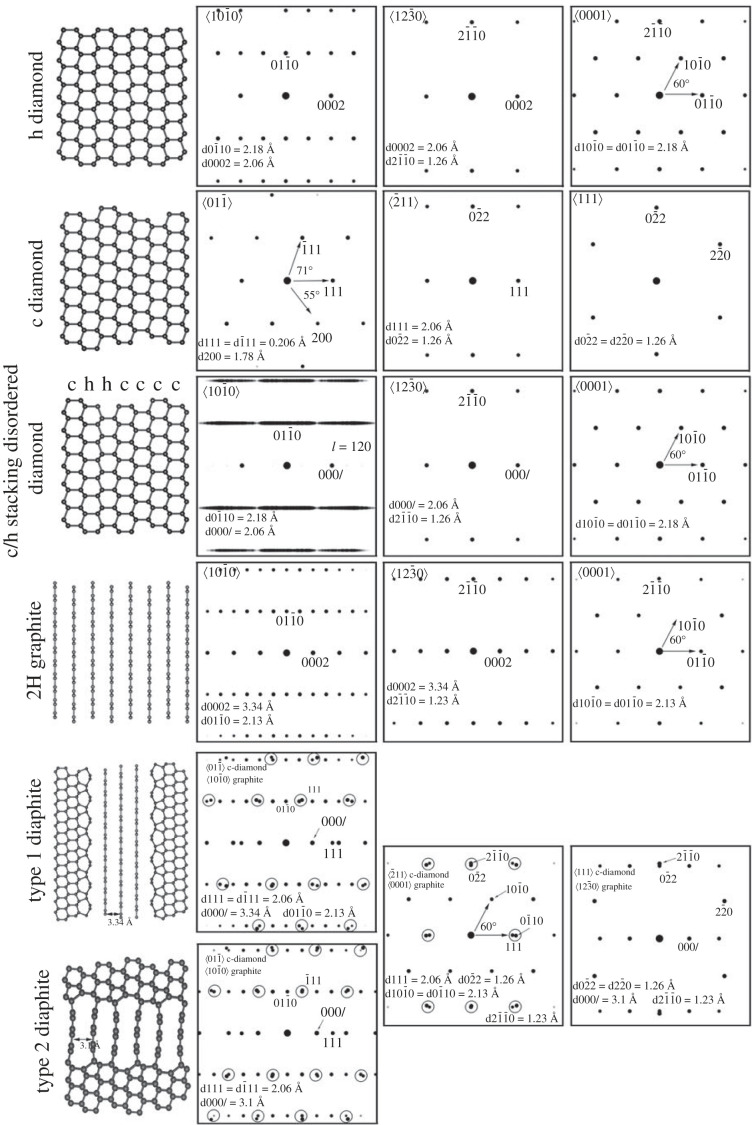
To further illustrate the measurement challenges, we show the calculated SAED patterns for h diamond, c diamond, c/h stacking disordered diamond, 2H graphite and type 1 and type 2 diaphites along major zone axes (figure 4). These structures are those reported from samples associated with h diamond [24–31]. A sufficiently large unit cell containing 120 layers with 50% cubic and 50% hexagonal stacking in a random stacking sequence was used for calculating diffraction patterns of c/h stacking disordered diamond. Since structural models for extended type 1 and type 2 diaphite structures are not available, their diffraction patterns were generated by adding the corresponding patterns of 2H graphite with the appropriate layer thickness, i.e. 3.34 and 3.10 Å, of type 1 and type 2 diaphites and c diamond. The reflections of c diamond and graphite are close to each other and expected to become one broad reflection for diaphites. In figure 4, the various structures and their calculated diffraction patterns are arranged according to the orientational relationships described in [27,54].
Figure 4.
Structure models and calculated diffraction patterns of h, c and c/h stacking disordered diamond as well as 2H graphite and diaphite along major projections. The arrangement of the diffraction patterns reveals the three-dimensional crystallographic relationship, reported by Garvie et al. [56] and Németh et al. [27], among the various structures. Double reflections marked by black circles for diaphite structures are expected to occur as a broad reflection.
The identification of h diamond based on diffraction data is unambiguous for the projection. Along this projection the h diamond reflections can be distinguished from those of c diamond, c/h stacking disordered diamond, graphite and diaphite (figure 4). The calculated electron diffraction pattern shows the distribution and the d spacings of the orthogonally arranged 0002 (2.06 Å) and (2.18 Å) reflections of h diamond, which are distinct from any projections of the other structures. However, discrete reflections for h diamond have not been reported from any natural or synthetic material. The corresponding projection for c diamond is with 2.06 Å d spacings for 111 and reflections and 71° between the 111g and vectors. The c/h stacking disordered diamond along can be recognized by the streaking of reflections. 2H graphite and type 1 and type 2 diaphites along graphite projection can be distinguished from h diamond by the occurrence of the 3.34 Å or the 3.10 Å d spacing of 000l reflections of the graphite units.
The diffraction pattern of h diamond in the orientation, perpendicular to projection, is indistinguishable from the crystallographically corresponding diamond and c/h stacking disordered diamond, and it is distinct from graphite and diaphite (figure 3). Since type 1 and type 2 diaphites are laterally intergrown, their projections other than are identical. Similarly, the d spacings and the distributions of the hexagonally arranged reflections of h diamond projected along are identical to c/h stacking disordered diamond projected along . Furthermore, similar patterns occur for graphite and diaphite, and the error of d value measurement makes the hexagonally arranged graphite (2.13 Å) and diaphite (2.13 Å) reflections indistinguishable from that (2.18 Å) of h diamond (figure 4). Thus, h diamond identification based on the projection is problematic.
Unambiguous h diamond identification requires tilting of a sample so as to produce discrete reflections on diffraction patterns. However, such patterns have to date not been reported. In addition, the occurrence of hexagonally arranged reflections associated with projections are not unique for h diamond even for sp3-bonded structures.
(e) . Domain structure and various intergrowths among c/h stacking disordered diamond, graphite and diaphite
Low-magnification TEM images of the Canyon Diablo specimens show 1–20 nm wide, and 100–300 nm long domains characterized by a sawtooth appearance and mottled texture (figure 5) [24,31]. The corresponding SAED patterns show spotty rings with streaking and smeared intensities. The reflections spread over a large area roughly corresponding to d spacings of 2.2 and 1.8 Å. The strongest reflections from some SAED patterns can be assigned to c diamond (figure 5a), though such an assignment only approximates the complexity of the patterns. The SAED pattern of figure 5a shows streaking of reflections from multiple c/h stacking disordered diamond domains. Other SAED patterns show approximately hexagonally arranged reflections with approximately 2.1 Å d spacings (figure 5b), which are consistent with c/h stacking disordered diamond as well as with type 2 diaphite intergrowth consisting of c diamond and graphene units.
The structure of a hard carbon grain was investigated from two FIB thinned lamellae, which were prepared from two areas after rotating the grain by 90° (figure 5c). The low-magnification TEM image of lamella 1 reveals a feathery texture (figure 5c), which may reflect previous graphitic layering arranged into bundles [31]. The corresponding SAED pattern, taken from an approximately 200 nm size area, is characterized by quasi-continuous rings, of which the strongest intensity can be indexed as c diamond (figure 5c). However, similar to figure 5a, the pattern displays streaking of reflections from multiple c/h stacking disordered diamond domains, and their associations with graphene layers are consistent with type 1 diaphite. The feathery texture is absent on the low-magnification TEM image of lamella 2 (figure 5d). The corresponding SAED pattern shows continuous rings and the intensity distribution around the 111 diamond spots reveals a quasi-sixfold symmetry, which can be explained with c/h stacking disordered diamond as well as with type 2 diaphite intergrowth.
Understanding the complexity of the samples requires the use of HRTEM images, which reveal abundant (111) c diamond stacking faults and twins along , i.e. they provide evidence for c/h stacking disordered diamond domains (figure 6). These domains are 1–5 nm wide [24] and they are evidenced by the sawtooth appearance on low-magnification TEM images (figure 5). The structures correspond to that of c/h stacking disordered diamond, which gives rise to the streaking and the d spacings previously associated with h diamond. Although discrete c diamond reflections along can be recognized, the overall diffraction features of the FFTs (figure 6b) are similar to the calculated patterns based on c–h stacking disordered diamond structure (figure 4).
Németh et al. [24] reported that multiple (111) and twins and stacking faults prevent the cubic symmetry of diamond for localized nanometre-sized regions and result in complex (011) twin intergrowths (figure 7a,b). Since the corresponding indices for c/h stacking disordered diamond are non-integer numbers, we report c diamond indices of this twin only. Although Németh et al. [24] reported {113} c diamond twin intergrowth also, the reinvestigation implies the reported structure is more consistent with (011) c diamond type (figure 7b). This twin gives rise to a second set of streaking at 71° with respect to the strong {111} c diamond or the {000l} c/h stacking disordered diamond streaking in FFT, which gives rise to the characteristic ring SAED patterns (figure 7a,b) and provides an explanation for the prominent sawtooth appearance of the low magnification TEM images (figure 5).
The occurrence of diaphite structures within c and c/h stacking disordered diamond gives rise to additional complexity (figure 8). These nanostructures display lattice fringe spacings of 3.4 Å, corresponding to the graphene interlayer spacings, and 2.1 Å, consistent with both graphite and 111 diamond reflections [27–31]. The 3.4 Å fringes occur systematically as few-layered graphene to graphitic domains and contiguous with the {111} diamond layers (figure 8). Their lateral extent varies up to a few nanometres and is consistent with type 1 diaphite. These structures terminate within the sp3-bonded lattice and give rise to type 2 diaphite (figure 8a,b). DFT calculations suggest the interlayer spacings of type 2 diaphite are compressed (3.1 Å) by the necessity of coherent bonding between the edges of the graphene layers and the {113} diamond surfaces (figure 8c). However, we should note that this 3.1 Å spacing cannot be reliably measured from the experimental HRTEM images.
HRTEM images show the diversity of type 1 and type 2 diaphite, and their various intergrowth structures within the grains (figure 8). Their presence is clearest in thin (less than 20 nm) samples (figure 8a,b) and is challenging to identify in samples thicker than approximately 20 nm due to the vertically superimposed nanodomains. However, the contributions of graphene and the c diamond units can be detected in FFTs. The thicker the sample, the more complex the image. An interesting example of complexity is shown in figure 8d, which displays vertically superimposed diaphites structures with crystallographically intergrown c/h stacking disordered diamond.
(f) . Explanation of the hexagonally arranged reflections
Discrete, hexagonal reflections with approximately 2.1 Å spacings were previously used as evidence for h diamond. These diffraction patterns are commonly shown together with electron-energy loss spectroscopy (EELS) data. Based on the lack of obvious spectral features below 288 eV (the main onset of the diamond peak) in C K-edge core-loss EELS data, it has been claimed that samples did not contain sp2-bonded structures and the hexagonal reflections were assigned to h diamond (Supplementary Material in [31])). However, this assignment raises issues because (i) a reference h diamond EELS is unavailable and the reported data cannot be distinguished from c/h stacking disordered diamond and (ii) the diffraction features are not unique for h diamond even when considering only sp3-bonded structures.
Our calculated diffraction patterns demonstrate that c/h stacking disordered diamond is indistinguishable from h diamond along (figure 4). The contribution of the c diamond stacking is hidden within hexagonally stacked diamond, and the c diamond reflections having 1.26 Å d spacing overlap with those of c/h stacking disordered diamond (1.26 Å). To identify the various stackings, 90° rotation would be necessary, which is not possible within a transmission electron microscope. However, there is abundant evidence for c/h stacking disordered diamond projected along (figures 5–8), thus we suggest a portion of the hexagonally arranged reflections is explained by this structure.
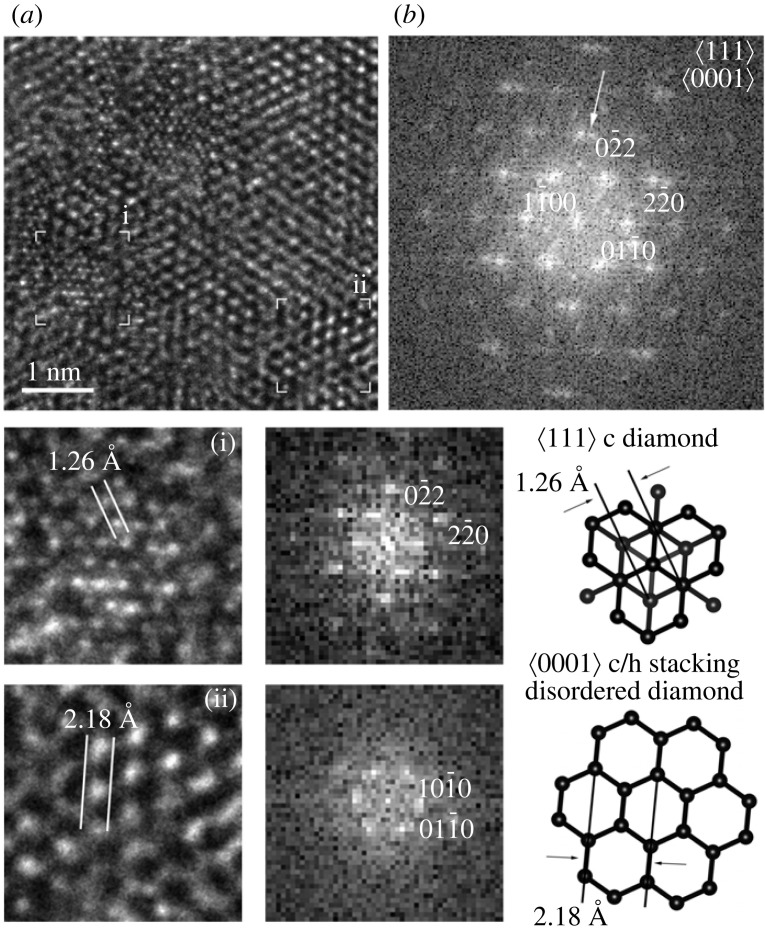
Ultra-high-resolution TEM (uHRTEM) images provided by aberration-corrected microscopes are necessary to resolve interatomic spacings below 1.3 Å, i.e. the 1.26 and 1.09 Å spacings corresponding to {220} and {113} diamond fringes. In a conventional (non-aberration corrected) HRTEM, only the 2.1 Å sets of {111} diamond fringes are visible. The uHRTEM image of figure 9a shows an intricate lattice fringe image. Its high resolution and the approximately 10° rotation between the cubic and the hexagonal stackings provide evidence for a unique c diamond and c/h stacking disordered diamond intergrowth. In certain areas of the image the 1.26 Å d spacing cross fringes (i) occur together with those of approximately 2.1 Å (ii). The FFT (figure 9b) of the image reveals split reflections having 1.26 Å d spacings with an approximately 10° rotation. We associate the FFT-calculated diffraction data from area i and ii with c diamond and c/h stacking disordered diamond, respectively.
Similar to c/h stacking disordered diamond, type 2 diaphite structures give rise to hexagonal reflections with 2.1 Å d spacings (figure 10). We note that the superimposed c diamond and graphene units of type 1 diaphite would also result in a similar pattern (figure 4). Type 2 diaphite projected along c diamond exhibits hexagonally arranged graphene layers inserted within and bonded at high angles to the sp3-bonded c diamond surfaces (figure 10). HRTEM images of type 2 diaphite from the Canyon Diablo hard carbon grains (figure 10) are characterized by elongated c diamond domains parallel to and subnanometre-sized regions containing approximately 2.1 Å fringes arranged in a hexagonal pattern. Németh et al. [24] interpreted figure 10a as two- and four-layer thick {113} c diamond twins. However, the DFT-based structure model (figure 10b) shows that such images are in fact consistent with type 2 diaphite and indicate that these nanostructures correspond to a nanocomposite material consisting of sp2- and sp3-bonded carbon regions. Type 2 diaphite contains c diamond, graphene and interface regions. By changing the volume of these regions, various type 2 diaphite structures can be generated and identified in HRTEM images (figure 10c,d). Several HRTEM images are dominated by c diamond and interface regions, and they are presumably vertically embedded within c diamond. It is an interesting question how their electronic structure and EELS data differ from c or c/h stacking disordered diamond. As the sample gets thicker, the identification of the c diamond units becomes challenging (figure 10d). However, the elongation of the domains and the streaking of reflections are indicative of type 2 diaphite (figure 10d).
4. What is lonsdaleite?
Lonsdaleite is the mineral name given to the h diamond component in the hard carbon grains from the Canyon Diablo iron meteorite [4]. Since its first description in 1967, natural and synthetic materials with diffraction data matching the Canyon Diablo lonsdaleite have been widely reported. For example, from meteorites [6–10,57], impact structures [11–13] and terrestrial sediments [14]. Structural features used for lonsdaleite identification are known from diamonds occurring in various terrestrial geological settings including ultrahigh-pressure metamorphic rocks [15] and cratonic lamproite colluviums [58], in highly strained, mechanically twinned pink diamonds [59] as well as in nanodiamonds found in primitive meteorites [25,29] and synthetic materials unrelated to shock [2,20,22,23]. While lonsdaleite and h diamond have been used as synonyms, it is necessary to distinguish between the two and use h diamond for the fully hexagonal h diamond polytype exclusively. Despite these numerous reports, our data show that the XRD reflections originally identified as lonsdaleite from the Canyon Diablo hard carbon grains arise from materials dominated by highly disordered c/h stacking combined with crystallographically intergrown diaphite, and not from a discrete h diamond component. This structural complexity gives rise to intricate HRTEM images and continuous streaking of reflections on diffraction patterns, consistent with the absence of three-dimensional repetitions, even on the nanometre scale. In conclusion, Canyon Diablo lonsdaleite is not a discrete phase, but instead is a nanocomposite of disordered c/h stacked diamond and diaphite.
Acknowledgements
We would like to dedicate this article to the late Paul F. McMillan for bringing our team together, his tireless enthusiasm for this work and his lasting contributions to the field of diamond research. We are grateful to the Buseck Center for Meteorites studies for the loan of samples for our research, to the staff and for use of the facilities in the Themis Titan HRTEM facility located at the Institute of Technical Physics and Materials Science, Centre for Energy Research and the John M. Cowley Center for High Resolution Electron Microscopy at Arizona State University. The authors acknowledge the European Synchrotron Radiation Facility for provision of synchrotron beamtime at the beamline ID27.
Footnotes
The black hard carbon grains found in some specimens of the Canyon Diablo iron meteorite have been described as ‘diamonds’ since their discovery in 1891 [5]. Subsequent work has shown these grains to have a complex structure and not pure cubic diamond. As such, in this paper we refer to these grains as ‘Canyon Diablo hard carbon grains’.
Ethics
This work did not require ethical approval from a human subject or animal welfare committee.
Data accessibility
This article has no additional data.
Declaration of AI use
We have used AI-assisted technologies in creating this article.
Authors' contributions
P.N.: conceptualization, investigation, methodology, validation, writing—original draft; L.A.J.G.: conceptualization, formal analysis, validation, writing—review and editing; C.G.S.: conceptualization, methodology, software, visualization, writing—review and editing.
All authors gave final approval for publication and agreed to be held accountable for the work performed therein.
Conflict of interest declaration
We declare we have no competing interests.
Funding
P.N. acknowledges financial support from the Hungarian National Research, Development and Innovation Office project NKFIH_KH126502 and NKFIH_ANN146305. L.A.J.G. was supported by a NASA Emerging Worlds grant no. NNX17AE56G.
References
- 1.Bundy FP, Kasper JS. 1967. Hexagonal diamond- a new form of carbon. J. Chem. Phys. 46, 3437-3446. ( 10.1063/1.1841236) [DOI] [Google Scholar]
- 2.Cowan GR, Dunnington BW, Holtzman AH. 1968. Process for synthesizing diamond. US patent 3401019-A. See https://patents.google.com/patent/US3401019A/en.
- 3.Hanneman RE, Strong HM, Bundy FP. 1967. Hexagonal diamonds in meteorites: implications. Science 155, 995-997. ( 10.1126/science.155.3765.995) [DOI] [PubMed] [Google Scholar]
- 4.Frondel C, Marvin UB. 1967. Lonsdaleite, a hexagonal polymorph of diamond. Nature 214, 587-589. ( 10.1038/214587a0) [DOI] [Google Scholar]
- 5.Foote AE.1891 A new locality for meteoritic iron with a preliminary notice of the discovery of diamonds in iron. Am. J. Sci. S3–42 (251), 413–417. ( 10.2475/ajs.s3-42.251.413) [DOI]
- 6.Daulton TL, Eisenhour DD, Bernatowicz TJ, Lewis RS, Buseck PR. 1996. Genesis of presolar diamonds: comparative high-resolution transmission electron microscopy study of meteoritic and terrestrial nano-diamonds. Geochim. Cosmochim. Acta 60, 4853-4872. ( 10.1016/S0016-7037(96)00223-2) [DOI] [Google Scholar]
- 7.Le Guillou C, Rouzaud JN, Remusat L, Jambon A, Bourot-Denise M. 2010. Structures, origin and evolution of various carbon phases in the ureilite Northwest Africa 4742 compared with laboratory-shocked graphite. Geochim. Cosmochim. Acta 74, 4167-4185. ( 10.1016/j.gca.2010.03.038) [DOI] [Google Scholar]
- 8.Kvasnytsya V, Wirth R, Dobrzhinetskaya L, Matzel J, Jacobsen B, Hutcheon I, Tappero R, Kovalyukh M. 2013. New evidence of meteoritic origin of the Tunguska cosmic body. Planet. Space Sci. 84, 131-140. ( 10.1016/j.pss.2013.05.003) [DOI] [Google Scholar]
- 9.Nakamuta Y, Toh S. 2013. Transformation of graphite to lonsdaleite and diamond in the Goalpara ureilite directly observed by TEM. Am. Mineral. 98, 574-581. ( 10.2138/am.2013.4341) [DOI] [Google Scholar]
- 10.Nestola F et al. 2020. Impact shock origin of diamonds in ureilite meteorites. Proc. Natl Acad. Sci. USA 117, 25 310-25 318. ( 10.1073/pnas.1919067117) [DOI] [PMC free article] [PubMed] [Google Scholar]
- 11.Masaitis V L. 1998. Popigai crater: origin and distribution of diamond-bearing impactites. Meteorit. Planet. Sci. 33, 349-359. ( 10.1111/j.1945-5100.1998.tb01639.x) [DOI] [Google Scholar]
- 12.Ohfuji H, Irifune T, Litasov K, Yamashita T, Isobe F, Afanasiev VP. 2015. Natural occurrence of pure nano-polycrystalline diamond from impact crater. Sci. Rep. 5, 14702. ( 10.1038/srep14702) [DOI] [PMC free article] [PubMed] [Google Scholar]
- 13.Hough RM, Gilmour I, Pillinger CT, Arden JW, Gilkes KWR, Yuan J, Milledge HJ. 1995. Diamond and silicon carbide in an impact melt rock from the Ries impact crater. Nature 378, 41-44. ( 10.1038/378041a0) [DOI] [Google Scholar]
- 14.Kennett DJ et al. 2009. Shock-synthesized hexagonal diamonds in Younger Dryas boundary sediments. Proc. Natl Acad. Sci. USA 106, 12 623-12 628. ( 10.1073/pnas.0906374106) [DOI] [PMC free article] [PubMed] [Google Scholar]
- 15.Shumilova T. G, Mayer E., Isaenko S. I. 2011. Natural monocrystalline lonsdaleite. Doklady Earth Sciences 441, 1552-1554. ( 10.1134/S1028334X11110201) [DOI] [Google Scholar]
- 16.Bundy FP, Bassett WA, Weathers MS, Hemley RJ, Mao HU, Goncharov AF. 1994. The pressure-temperature phase and transformation diagram for carbon; updated through 1994. Carbon 34, 141-153. ( 10.1016/0008-6223(96)00170-4) [DOI] [Google Scholar]
- 17.Erskine DJ, Nellis WJ. 1991. Shock-induced martensitic phase-transformation of oriented graphite to diamond. Nature 349, 317-319. ( 10.1038/349317a0) [DOI] [Google Scholar]
- 18.Decarli PS. 1995. Shock Wave Synthesis of Diamond and other phases. MRS Online Proceedings 383. ( 10.1557/PROC-383-21) [DOI] [Google Scholar]
- 19.Turneaure SJ, Sharma SM, Volz TJ, Winey JM, Gupta YM. 2017. Transformation of shock-compressed graphite to hexagonal diamond in nanoseconds. Sci. Adv. 3, eaao3561. ( 10.1126/sciadv.aao3561) [DOI] [PMC free article] [PubMed] [Google Scholar]
- 20.Yagi T, Utsumi W, Yamakata M, Kikegawa T, Shimomura O. 1992. High-pressure diffraction study of the phase-transformation from graphite to hexagonal diamond at room temperature. Phys. Rev. B. 46, 6031-6039. ( 10.1103/physrevb.46.6031) [DOI] [PubMed] [Google Scholar]
- 21.Khaliullin RZ, Eshet H, Kuhne TD, Behler J, Parrinello M. 2011. Nucleation mechanism for the direct graphite-to-diamond phase transition. Nat. Mater. 10, 693-697. ( 10.1038/nmat3078) [DOI] [PubMed] [Google Scholar]
- 22.Isobe F, Ohfuji H, Sumiya H, Irifune T. 2013. Nanolayered diamond sintered compact obtained by direct conversion from highly oriented graphite under high pressure and high temperature. J. Nanomater. 380136, 1–6. ( 10.1155/2013/380165) [DOI] [Google Scholar]
- 23.Yoshiasa A, Murai Y, Ohtaka O, Katsura T. 2013. Detailed structures of hexagonal diamond (lonsdaleite) and Wurtzite-type BN. Jpn. J. Appl. Phys. 42, 1694-1704. ( 10.1143/JJAP.42.1694) [DOI] [Google Scholar]
- 24.Németh P, Garvie LA, Aoki T, Dubrovinskaia N, Dubrovinsky L, Buseck PR. 2014. Lonsdaleite is faulted and twinned cubic diamond and does not exist as a discrete material. Nat. Commun. 5, 5447. ( 10.1038/ncomms6447) [DOI] [PubMed] [Google Scholar]
- 25.Németh P, Garvie LAJ, Buseck PR. 2015. Twinning of cubic diamond explains reported nanodiamond polymorphs. Sci. Rep. 5, 18381. ( 10.1038/srep18381) [DOI] [PMC free article] [PubMed] [Google Scholar]
- 26.Murri M et al. 2019. Quantifying hexagonal stacking in diamond. Sci. Rep. 9, 10334. ( 10.1038/s41598-019-46556-3) [DOI] [PMC free article] [PubMed] [Google Scholar]
- 27.Németh P et al. 2020. Diamond-graphene composite nanostructures. Nano Lett. 5, 3611-3619. ( 10.1021/acs.nanolett.0c00556) [DOI] [PMC free article] [PubMed] [Google Scholar]
- 28.Németh P, McColl K, Garvie LAJ, Salzmann CG, Murri M, McMillan PF. 2020. Complex nanostructures in diamond. Nat. Mater. 19, 1126-1131. ( 10.1038/s41563-020-0759-8) [DOI] [PubMed] [Google Scholar]
- 29.Németh P et al. 2021. Diaphite-structured nanodiamonds with six- and twelve-fold symmetries. Diam. Relat. Mater. 119, 108573. ( 10.1016/j.diamond.2021.108573) [DOI] [Google Scholar]
- 30.Németh P, McColl K, Garvie LAJ, Corà F, Salzmann CG, McMillan PF. 2022. Impact-formed complex diamond-graphene nanostructures. Resolut. Discov. 6, 1-6. ( 10.1556/2051.2021.00089) [DOI] [Google Scholar]
- 31.Németh P et al. 2022. Shock-formed carbon materials with intergrown sp3- and sp2-bonded nanostructured units. Proc. Natl Acad. Sci. USA 119, e2203672119. ( 10.1073/pnas.2203672119) [DOI] [PMC free article] [PubMed] [Google Scholar]
- 32.Németh P, Garvie LAJ. 2023. Questionable lonsdaleite identification in ureilite meteorites. Proc. Natl Acad. Sci. USA 120, e2304890120. ( 10.1073/pnas.2304890120) [DOI] [PMC free article] [PubMed] [Google Scholar]
- 33.Treacy MMJ, Newsam JM, Deem MW. 1991. A general recursion method for calculating diffracted intensities from crystals containing planar faults. Proc. R. Soc. A 433, 499-520. ( 10.1098/rspa.1991.0062) [DOI] [Google Scholar]
- 34.Malkin TL, Murray BJ, Salzmann CG, Molinero V, Pickering SJ, Whale TF. 2015. Stacking disorder in ice. Phys. Chem. Chem. Phys. 17, 60-76. ( 10.1039/C4CP02893G) [DOI] [PubMed] [Google Scholar]
- 35.Salzmann CG, Murray BJ, Shephard JJ. 2015. Extent of stacking disorder in diamond. Diam. Relat. Mater. 59, 69-72. ( 10.1016/j.diamond.2015.09.007) [DOI] [Google Scholar]
- 36.Jones AP, McMillan PF, Salzmann CG, Alvaro M, Nestola F, Prencipe M, Dobson D, Hazael R, Moore M. 2016. Structural characterization of natural diamond shocked to 60 GPa; implications for Earth and planetary systems. Lithos 265, 214-221. ( 10.1016/j.lithos.2016.09.023) [DOI] [Google Scholar]
- 37.Smith RL, Vickers M, Rosillo-Lopez M, Salzmann CG. 2019. Stacking disorder by design: factors governing the polytypism of silver iodide upon precipitation and formation from the superionic phase. Cryst. Growth Des. 19, 2131-2138. ( 10.1021/acs.cgd.8b01715) [DOI] [Google Scholar]
- 38.Sharif Z, Salzmann CG. 2022. Comparison of the phase transitions of high-pressure phases of ammonium fluoride and ice at ambient pressure. J. Chem. Phys. 156, 014502. ( 10.1063/5.0077419) [DOI] [PubMed] [Google Scholar]
- 39.Dunn PJ, Mandarino JA. 1987. Formal definitions of type mineral specimens. Am. Mineral. 72, 1269-1270. ( 10.1007/BF01162483) [DOI] [Google Scholar]
- 40.Garvie LAJ, Németh P. 2009. The structure of Canyon Diablo ‘diamonds’. LPSC 40, 1346. See https://ui.adsabs.harvard.edu/abs/2009LPI....40.1346G/abstract.
- 41.Ksanda CJ, Henderson EP. 1939. Identification of diamond in the Canyon Diablo iron. Am. Mineral. 24, 677-680. [Google Scholar]
- 42.Playford HY, Whale TF, Murray B, Tucker MG, Salzmann CG. 2018. Analysis of stacking disorder in ice I using pair distribution functions. J. Appl. Crystallogr. 51, 1211-1220. ( 10.1107/S1600576718009056) [DOI] [Google Scholar]
- 43.Cowley JM, Mani RC, Sunkara MK, O'Keeffe M, Bonneau C. 2004. Structures of carbon nanocrystals. Chem. Mater. 16, 4905-4911. ( 10.1021/cm0491429) [DOI] [Google Scholar]
- 44.Brett R, Higgins GT. 1967. Cliftonite; a proposed origin, and its bearing on the origin of diamonds in meteorites. Geochim. Cosmochim. Acta 33, 1473-1484. ( 10.1016/0016-7037(69)90151-3) [DOI] [Google Scholar]
- 45.Garvie. 2016. Observations on a 10-kg graphite nodule fromthe Canyon Diablo (IAB-MG) iron meteorite. Lunar Planet. Sci. Conf. XLVII, 2567 (abst). See https://www.hou.usra.edu/meetings/lpsc2016/pdf/2567.pdf. [Google Scholar]
- 46.Kunz GF, Huntington OW. 1893. On the diamond on the diamond in the Canyon Diablo meteoric iron and on the hardness of carborundum. Am. J. Sci. 146, 470-473. ( 10.2475/ajs.s3-46.276.470) [DOI] [Google Scholar]
- 47.Lipschutz M, Anders E. 1961. The record in the meteorites-IV: origin of diamonds in iron meteorites. Geochim. Cosmochim. Acta 24, 83-105. ( 10.1016/0016-7037(61)90009-6) [DOI] [Google Scholar]
- 48.Carter NL, Kennedy GC. 1964. Origin of diamonds in the Canyon Diablo and Novo Urei meteorites. J. Geophys. Res. 69, 2403-2421. ( 10.1029/JZ069i012p02403) [DOI] [Google Scholar]
- 49.Goresy AE. 1965. Mineralbestand und Strukturen der Graphit-und Sulfideinschlüsse in Eisenmeteoriten. Geochim. Cosmochim. Acta 29, 1131-1136. ( 10.1016/0016-7037(65)90116-X) [DOI] [Google Scholar]
- 50.Nininger HH. 1939. Diamonds in Canyon Diablo, Arizona, meteorites. Popular Astron. 47, 504-507. ( 10.1111/j.1945-5100.1939.tb00239.x) [DOI] [Google Scholar]
- 51.Nininger HH. 1956. Arizona's meteorite crater. Denver, CO: World Press, Inc. [Google Scholar]
- 52.Heymann D. 1964. Origin of the Canyon Diablo no. 2 and no. 3 meteorites. Nature 204, 819-820. ( 10.1038/204819a0) [DOI] [Google Scholar]
- 53.Moore CB, Birrell PJ, Lewis CF. 1967. Variations in the chemical and mineralogical composition of rim and plains specimens of the Cañon Diablo meteorite. Geochim. Cosmochim. Acta 31, 1885-1892. ( 10.1016/0016-7037(67)90129-9) [DOI] [Google Scholar]
- 54.Luo K et al. 2022. Coherent interfaces govern direct transformation from graphite to diamond. Nature 607, 486-491. ( 10.1038/s41586-022-04863-2) [DOI] [PMC free article] [PubMed] [Google Scholar]
- 55.Zhang S et al. 2021. Narrow-gap, semiconducting, superhard amorphous carbon with high toughness, derived from C60 fullerene. Cell Rep. Phys. Sci. 2, 100575. ( 10.1016/j.xcrp.2021.100575) [DOI] [Google Scholar]
- 56.Garvie LAJ, Nemeth P, Buseck PR. 2014. Transformation of graphite to diamond via a topotactic mechanism. American Mineralogist 99(2–3), 531-538. ( 10.2138/am.2014.4658) [DOI] [Google Scholar]
- 57.Christ O, Barbaro A, Brenker FE, Nimis P, Novella D, Domeneghetti MC, Nestola F. 2022. Shock degree and graphite geothermometry in ureilites NWA 6871 and NWA 3140. Meteorit. Planet. Sci. 57, 1861-1878. ( 10.1111/maps.13907) [DOI] [Google Scholar]
- 58.Presser LBJ, Sikder MA. 2022. Raman spectroscopic analysis of diamonds and its mineral inclusions from ‘Lamproites’ in the Capiibary, San Pedro Dpto., Paraguay. Hist. Nat. 12, 5-19. ( 10.13140/RG.2.2.35932.26240) [DOI] [Google Scholar]
- 59.Gaillou E, Post JE, Bassim ND, Zaitsev A, Rose TR, Fries M, Stroud R, Steele A, Butler JE. 2010. Spectroscopic and microscopic characterization of color lamellae in natural pink diamond. Diam. Relat. Mater. 19, 1207-1220. ( 10.1016/j.diamond.2010.06.015) [DOI] [Google Scholar]
Associated Data
This section collects any data citations, data availability statements, or supplementary materials included in this article.
Data Availability Statement
This article has no additional data.


