Abstract
Numerical simulation of the electromagnetic, thermal and mechanical responses of the human body to different stimuli in MRI safety, antenna research, electromagnetic tomography, and electromagnetic stimulation is currently limited by the availability of anatomically adequate and numerically efficient cross-platform computational models or “virtual humans”. The objective of this study is to provide a comprehensive review of modern human models and body region models available in the field and their important features. The major emphasis is made on various model applications in Computational Electromagnetics (CEM) and antenna-related research.
Keywords: CEM applications in medical fields, electromagnetic safety assessment, specific absorption rate, on-body and in-body antennas, cellphone radiation, brain-computer interfaces, magnetic resonance imaging (MRI) systems, passive or active implanted devices, virtual humans, numerical simulations, finite-element method, U.S. Food and Drug Administration (FDA), The Federal Communications Commission (FCC), The National Institute of Standards and Technology (NIST)
I. Virtual Humans and their Major Applications
A. Virtual Humans
Computational modeling with virtual humans combines mathematics, physics, anatomy, physiology, and computer science to study the behaviors and reactions of complex biomedical problems in-silico. The National Institutes of Health states that “modeling can expedite research by allowing scientists to conduct thousands of simulated experiments by computer in order to identify the actual physical experiments that are most likely to help the researcher find the solution to the problem being solved” [1]. Among other computer simulation tools, realistic computational human models or “virtual humans” are becoming a significant component of modern biomedical research.
B. Use of Computational Human Models for Development of Medical Devices
In the past decade, general biomedical research has emerged as one of the industries showing great potential to stimulate the US economy. Table I lists the major medical device market sectors with the potential need for computational human phantoms. In the case of general medical device development, relevant study areas include fluid dynamics (e.g., shear stress and stagnation calculations in ventricular assist devices), solid mechanics (e.g., maximum stress locations in a hip implant), electromagnetics and optics (e.g., radiofrequency dosimetry in magnetic resonance imaging), ultrasound propagation (e.g., absorbed energy distribution for therapeutic ultrasound), and thermal propagation (e.g., radiofrequency and laser ablation devices) [2].
Table I.
Major Medical Device Market Sectors with the Potential Use of Computational Human Models
| Market Sectors | Market Size (2015) | Annual Growth (%) | Market Size (out year) |
|---|---|---|---|
| General Medical Devices/Implants | $260 Ba | 6.1b | $302 B (2017)b |
| Medical Imaging Safety (MRI, CT)a | $24.4 B | 4.0 | $35.4 B (2019) |
| Electric/Electromagnetic Therapeuticsa | $4.2 B | 8.2 | $6.0 B (2018) |
| Diagnostics – Traumatic Brain Injuryd | $1.54 B | 3.8 | $2.0 B (2017) |
| Diagnostics – Endoscopye | $23.3 B | 6.6 | $75.8 B (2022) |
Espicom Business Intel
Lucintel
Transparency Market Res.
GlobalData
Visiongain
C. Use of Computational Human Models in Automotive Safety Research
Along with the medical device field, computational human body models have been actively developed for biomechanical and automotive safety research over the past three decades [3]–[12]. Although vehicular crash safety performances are evaluated with crash test dummies regulated by respective federal governments, it is believed that examination of the impact biomechanics with computational human body models would provide better understandings of injury mechanisms relevant to automotive crashes. Body sizes of computational human models in automotive research are selected from a review of standardized anthropometries [13], the most common being an American adult male 50th percentile (commonly called AM50). One popular example is the Total Human Model for Safety, which is an extremely detailed finite-element computational model of the human body used in various impact scenarios. It has been actively developed by Toyota Motor Corporation and Toyota Central R&D Labs since approximately 2000 [4]–[8]. Another example is given by the very detailed Global Human Body Models Consortium products [9]–[12] developed by General Motors, Honda, Nissan, etc., and sponsored by the U.S. National Highway Traffic Safety Administration. An example is given in Fig. 1. These human models are also widely used for university research; examples are given in [14],[15]. The automotive-safety models do not correspond to real subjects, but they usually have extremely high-quality surface quadrilateral CAD (Computer Aided Design) surface representations best suited for accurate FEM modeling, including mechanical applications [16].
Fig. 1.
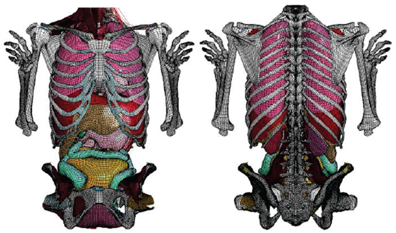
Fo5-O quadrilateral model resolution in the abdominal region [12].
In general, we understand the CAD format as a representation such as in ACIS, ProE, Catia, where smooth surfaces are defined (not volumetric “meshes”), and most important there is a consistent (watertight and manifold) topology of shapes, faces and edges. What matters for this article is just a practical and proven FEM-meshability, i.e. it is enough to have a consistent surface model coarse enough to be meshed into tetrahedra or other for FEM electromagnetic or structural simulations. The surface model may be based on triangles, quadrilaterals, or nonuniform rational basis splines (NURBS). Every CAD model and/or its parts could be 3D printed.
D. Use of Human Models in Electromagnetic Studies
For general electric and magnetic fields applications, computational human models are used to perform safety and performance evaluations on a variety of medical devices [2]. These include electrophysiology monitoring devices such as EEG (Electroencephalography), ECG (Electrocardiography), MEG (Magnetoencephalography), and MRI systems. MR conditional implanted devices like orthopedic devices, stents, pacemakers, and neurostimulators are other devices benefiting from these models along with devices for radiofrequency ablation, optical coherence tomography, fluorescence spectroscopy, laser surgery, and optical therapy. In application to antennas, computational human models are used in the modeling of body-centric wireless communications such as the safety and performance evaluations of cellphone radiation, implanted antennas, microwave ablation, and microwave imaging systems.
E. Use of Computational Human Models in Radiology
In radiology, human models are applied for ionizing radiation dosimetry studies. The design and application of human models (mostly voxel models) in radiation dosimetry pertinent to organ doses resulting from CT and Positron Emission Tomography or PET examinations, as well as nuclear exposure in power plants, have been documented in Refs. [17]–[20].
II. Overview of Human Models for CEM Research
A. Full-Body Human Models
Table II, which is an updated extension of the IEEE document [21], lists major full-body models currently available for computational electromagnetics (CEM) and radiological simulations along with major anatomical information and country of origin. It specifies the model type, resolution, availability of the original data etc., availability of a free version, and other model characteristics. Models based on the Visible Human Project® [22]–[26] are marked blue.
Table II.
Major Anatomical Full-Body Human Models for CEM and Radiological Simulations (After 2004)
| Entity/Country | Model Name | G/A/H/W | Da | TYPE | RES, mm2 | FV | D | Ref. |
|---|---|---|---|---|---|---|---|---|
| IT’IS Found. Switzerland | Glenn | m/84/173/61.1 | N | V | 0.5×0.5×1.0h 0.9×0.9×2b |
N | Y | [28],[29] |
| IT’IS Found. Switzerland | FATS | m/37/182/119 | N | V | 0.5×0.5×1.0h 0.9×0.9×2b |
N | Y | [28],[29] |
| IT’IS Found. Switzerland | DUKE | m/34/177/70.3 | N | V/S | 0.5×0.5×1.0h 0.9×0.9×2b |
Y | Y | [27]–[29] |
| IT’IS Found. Switzerland | ELLA | f/26/163/57.3 | N | V/S | 0.5×0.5×1.0h 0.9×0.9×2b |
Y | Y | [[27]–[29] |
| IT’IS Found. Switzerland | LOUIS | m/14/168/49.7 | N | V | 0.5×0.5×1.0h 0.9×0.9×2b |
N | Y | [[28],[29] |
| IT’IS Found. Switzerland | BILLIE | f/11/149/34.0 | N | V/S | 0.5×0.5×1.0h 0.9×0.9×2b |
Y | Y | [27]–[29] |
| IT’IS Found. Switzerland | EARTHA | f/8/136/29.9 | N | V | 0.5×0.5×1.0h 0.9×0.9×2b |
N | Y | [28],[29] |
| IT’IS Found. Switzerland | DIZZY | m/8/137/25.4 | N | V | 0.5×0.5×1.0h 0.9×0.9×2b |
N | Y | [28],[29] |
| IT’IS Found. Switzerland | THELONIOUS | m/6/115/18.6 | N | V/S | 0.5×0.5×1.0h 0.9×0.9×2b |
Y | Y | [27]–[29] |
| IT’IS Found. Switzerland | ROBERTA | f/5/109/17.8 | N | V | 0.5×0.5×1.0h 0.9×0.9×2b |
N | Y | [[28],[29] |
| IT’IS Found. Switzerland | NINA | f/3/92/13.9 | N | V | 0.5×0.5×1.0h 0.9×0.9×2b |
N | N | [28],[29] |
| IT’IS Found. Switzerland | CHARLIE | f/8w/na/4.3 | N | V | 0.5×0.5×1.0h 0.9×0.9×2b |
N | N | [28],[29] |
| China Acad. of Tel. Res. | CHINESE MALE | m/35/172/64 | Y1 | V/S | 1×1×1 | N | N | [30],[33],[34] |
| China Acad. of Tel. Res. | CHINESE FEMALE | f/22/162/54 | Y1 | V/S | 1×1×1 | N | N | [30],[33],[34] |
| Huazhong Univ, China | CDH M2 | m/166 | Y2 | V/S | 0.1×0.1×0.2 | N | N | [31],[33],[34] |
| Huazhong Univ, China | CHINESE REF. MAN | m/166 | Y | S | 2×2×2 | N | Y | [32]–[34] |
| Natl. Inst. of Inform. and Comm. Technol., Japan | NAGAOKA MAN (TARO) | m/22/173/65 | N | V | 2×2×2 | N | N | [35] |
| Natl. Inst. of Inform. and Comm. Technol., Japan | NAGAOKA WOMAN | f/22/160/53 | N | V | 2×2×2 | N | N | [35] |
| ETRI, Korea Flanyang University | KOREAN MAN | m/21/176/67 | N | V/S | 1×1×1 (head) 3×3×3(body) |
N | N | [36],[37] |
| ETRI, Korea Flanyang University | KOREAN CHILD | m/7/122.4/25.5 | N | V | 1×1×3 | N | N | [38] |
| ETRI, Korea Flanyang University3 | KOREAN WOMAN | f/26/161/54 | N | V | 2×2×2 | N | N | [39] |
| Nat. Radiological Protection Board, UK | NAOMI | f/23/163/60 | N | V | 2×2×2 | N | N | [40] |
| REMCOM, PennState | Male/Female | m/f | Y | V | 5×5×5(both) | N | Y | [41] |
| Helmholtz Zentrum Munchen, Germany CST AG, Germany |
BABY | f/8w/57/4.2 | N | V | 0.85×0.85×4 | N | N | [42],[40] |
| CHILD | f/7/115/21.7 | N | V | 1.54×1.54×8 | N | N | [42] | |
| DONNA | f/40/176/79 | N | V | 1.88×1.88×10 | N | N | [42] | |
| EMMA | f/26/170/81 | N | V | 0.98×0.98×10 | N | N | [42] | |
| GUSTAV | m/38/176/69 | N | V | 2.1×2.1×8 | N | N | [42] | |
| LAURA | f/43/163/51 | N | V | 1.88×1.88×5 | N | N | [42] | |
| HUGO, posable | m/38/187/113 | Y | V | 1×1×1 | N | Y | [43] | |
| U Texas Austin, USA | AUSTIN MAN | m/38/187/113 | Y | V | 1×1×4 | Y | Y | [44], [45] |
| U Texas Austin, USA | AUSTIN WOMAN | f/60/162/88 | Y | V | 1×1×4 | Y | Y | [44], [45] |
| Duke University Medical Center, USA | XCAT FAMILY | Orig: f/60/162/88 m/38/187/113 | Y | NURBS&S4 | variable | Y | Y | [46]–[52] |
| NEVA EM LLC, WPI, USA | VHP-Female (NELLY) | f/60/162/88 | Y | FEM | variable | [53]–[58] | ||
| NEVA EM LLC, WPI, USA | VHP-MALE | m/38/180/90.3 | Y | FEM | variable | [59] |
The most comprehensive model family in Table II is certainly the virtual population from IT’IS Foundation Switzerland [27]–[29]. Major members of the virtual population are shown in Fig. 2.
Fig. 2.
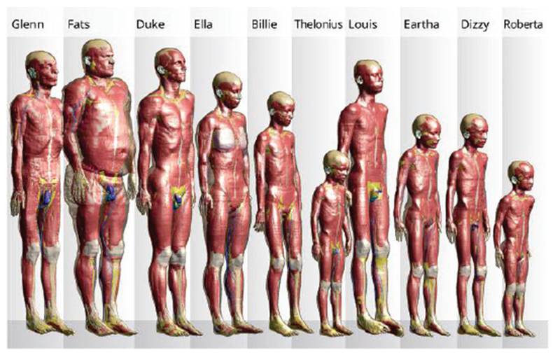
Members of the Virtual Population [27]–[29] – voxel models. Many of the models are posable.
Some models in Table II are based on the legendary Visible Human Project®. In 1990, the U.S. National Library of Medicine started this project, building a digital image library of volumetric data representing a complete adult human male and female. This Visible Human Project® (VHP) included digitized photographic images from cryosectioning, digital images derived from computerized tomography, and digital magnetic resonance images of two cadavers. Even today, the corresponding cryosection images (24 bits of color, pixel resolution of 0.33 mm) provide state-of-the-art resolution of muscle, other soft tissues as well as bone. The datasets have applied to a wide range of virtual reality uses by over 3500 licensees in 64 countries [22],[26].
Table II is primarily based on Refs. [21], [28]–[59] and does include all the models, indeed. The number of voxel-based full-body human models developed so far approaches 40 [19]. A detailed list of human phantoms developed as of 2010 is provided in Ref. [19] and a more recent (covering the period up to 2014) list is provided in Ref. [21]; voxel models have been separately reviewed in Ref. [60]. Fig. 3 shows a FEM-compatible VHP-Female model (also called NELLY) of NEVA Electromagnetics [53]–[58].
Fig. 3.
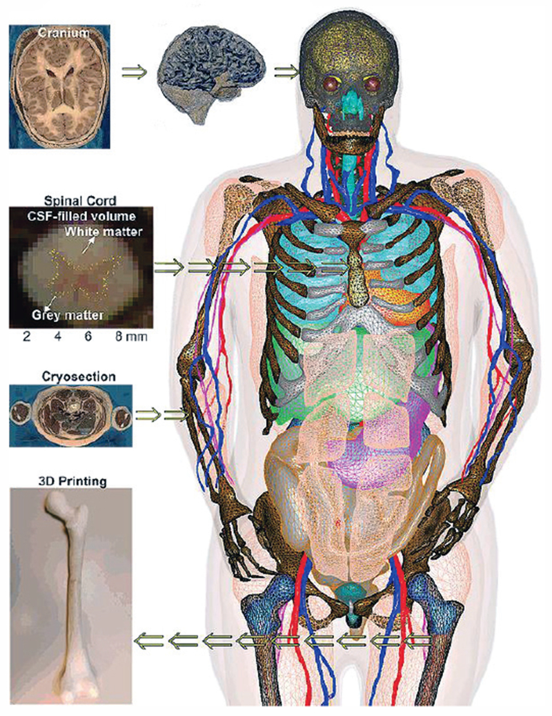
VHP-Female v. 3.0 CAD model [53]–[58] with about 250 individual parts; some tissues have been removed for visual clarity.
B. Detailed Models of Body Regions Including Anisotropic Models
Table III based on Refs. [60]–[81] lists some detailed models of individual body regions known to the authors and mostly used for accurate bioelectromagnetic modeling at low and high frequencies. Of special note is the detailed MIDA (Multimodal Imaging-Based Detailed Anatomical) human-head model [61] shown in Fig. 4, which includes 153 structures and anisotropic white matter information.
Table III.
Major Detailed Models of Body Regions (After 2004)
| Entity/Country | Model Name | Region | Da | TYPE | RES, mm2 | FV | D | Ref. |
|---|---|---|---|---|---|---|---|---|
| IT’IS Found. Switzerland FDA, USA | MIDA, anisotropy included | Head, neck (female, 29 years) | N | V/s | 0.5×0.5×0.5 | Y | N | [61] |
| University of Wisconsin-Madison, USA | HUMAN BREASTS | Human breast | N | V | Y | N | [62]–[65] | |
| Universidade de Lisboa, Portugal | BRAIN/SPINAL CORD, anisotropy included | Head (female, 20 years), spinal cord (from DUKE) | N | FEM | T1/T2: 1×1×1 DTI: : 1.3×1.3×3.5 |
N | N | [66],[67]5 |
| University of Minnesota, USA | PELVIS Biomechanical modeling | Pelvic region (female, 20 years) | N | FEM | NA | N | N | [68],[69] |
| Ministry of Education, Japan | Based on TARO [34] | All separate body regions for m/22/173/65 | N | V | 2×2×2 | Y | [70] | |
| Mass General Hospital, USA | Connectome Project, brain anisotropy and brain fiber | Cortical reg., patient-specific | Y | v/s | 1.0×1.0×1.0 | Y | N | [71]–[75] |
| Max Planck Inst, for Human Cognitive and Brain Sciences, Germany | MGDM | Cortical reg., patient-specific | N | S | 1.0×1.0×1.2 | Y | N | [76]–[81] |
| The Third Military Medical University and The Chinese University of Hong Kong | CMODEL | Voxel Human Head | Y | V | 0.25×0.25×0.25 | N | N | [60] |
Abbreviations and comments:
G/A/H/W – Gender/Age/Height/Weight; Da – Original image dataset made available for independent evaluation (Y/N); TYPE (V – voxel; S – surface-based model, but without proven FEM meshability; FEM – surface-based FEM-meshable model); RES – Lowest image resolution (before or after post-processing) of the model declared by the provider (h=head, b=body); FV - Free version for available (Y/N); D – Deformable/posable (Y/N);
The original link cited in [33] http://www.chinesevisiblehuman.com is not responding (5/7/2016);
The original link cited in [31] http://www.vch.org.cn/ is not responding (5/7/2016);
More references including voxel, surface, and tetrahedral models are available from http://hurel.hanyang.ac.kr/;
XCAT family is not directly FEM-meshable but Simpleware has created a FEM meshable model based on XCAT (http://www.humanbodymodels.com/. 2013);
Fig. 4.
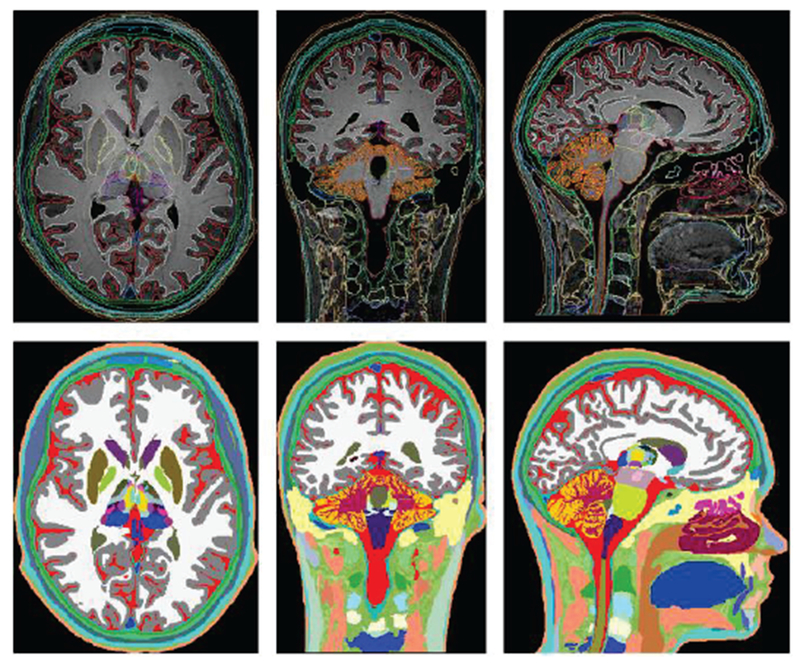
Axial, coronal, and sagittal views of the segmented head and neck (top row) of the MIDA head and color-coded label maps (bottom row) [61].
Another source of note is an open-source project called BodyParts3D [70]. This active project has been funded by the Ministry of Education of Japan. The goal of the project is to create “a dictionary-type database for anatomy in which anatomical concepts are represented by 3D structure data that specify corresponding segments of a 3D whole body model for an adult human male.” Geometries for the database were constructed from the voxel human model TARO [35]. The project is an online database providing native 3D models of rendered body parts for download. This database has been used by Wolfram Alpha Human Anatomy Tool [82].
We must separately mention a very comprehensive and detailed repository of human breast voxel models [62]–[65] intended for breast cancer and radio-frequency ablation studies.
Finally in this section, we point out automatic (or patient-specific) cranium model generation (brain segmentation and cortical surface modeling) packages from Massachusetts General Hospital (MGH) [71]–[75] and Max Planck Institute [76]–[81], one of which (FreeSurfer of MGH) is a freeware.
C. Detailed Models of Pregnant Women
Table IV based on Refs. [28],[29], [83]–[93] lists computational models of a pregnant woman and/or a fetus currently available for electromagnetic and radiological simulations. Almost all of them (except for Refs.[86],[90]) are based on insertion of a fetus or its modification into an existing non-pregnant female model(s). At the same time, the models presented in [86],[90] cover the abdominal region only.
Table IV.
Major Computational Pregnant-Woman Models (after ~2004).
| Entity/Country | Model Name | A/H/W | Da | TYPE | RES, mm3 | FV | D | Ref. |
|---|---|---|---|---|---|---|---|---|
| IT’IS Found., Switzerland | PREGNANT WOMAN1 | 26/163/57.3 3, 7, 9 months fetus |
N | V | 0.5×0.5×1.0 head 0.9×0.9×2 body |
Y | N | [28],[29] |
| Natl. Inst. of Inform. and Comm. Technol., Japan | PREGNANT WOMAN (based on non-pregnant model [35]) | 22/160/53 12, 20, 23, 26, 29, 32 and 33 weeks fetus |
N | V | 2×2×2 | Y | N | [83],[84],[85] |
| Imperial College, UK | PREGNANT WOMAN2 | 28 weeks fetus | N | V | 1×1×5 | N | N | [86] |
| Health Protection Agency, UK | PREGNANT WOMAN3 | 23/163/60 8, 13, 26, 38 weeks fetus |
N | V | 2×2×2 | N | N | [87] |
| Graz University of Technology, Austria | SILVY | 89 kg 30 weeks fetus |
N | V | 2×2×7 | N | N | [88] |
| Helmholtz Zentrum Munchen, Germany CST AG, Germany |
KATJA | 43/163/62 24 weeks fetus |
N | V | 1.8×1.8×4.8 | N | N | [89] |
| Rensselaer Poly. Institute, NY, USA | PREGNANT WOMAN4 | 30 weeks fetus | N | V | 6×6×7 | N | N | [90] |
| Rensselaer Poly. Institute, NY, USA | RPI P-3, P-6, P-95 | first, second, third trimesters fetus | N | V/S/NURBS | 6×6×7 for fetus | N | N | [91] |
| NEVA EM LLC, WPI | PREGNANT WOMAN6 | f/60/162/88 | Y | FEM | 3×3×3 | N | N | [92],[93] |
All models in Table IV are voxel models, except for Ref. [91] which used B-splines or NURBS while some parts of the body are adopted from the Visible Human Project [23]–[26] and Refs. [92],[93] which use the FEM meshable CAD format. One of the investigated concerns has been a significant electric current density, which may develop in the highly conductive amniotic fluid surrounding the fetus and subject to an external time-varying magnetic field [87],[88]. Fig. 6 shows a voxel model family from Ref. [83].
Fig. 6.
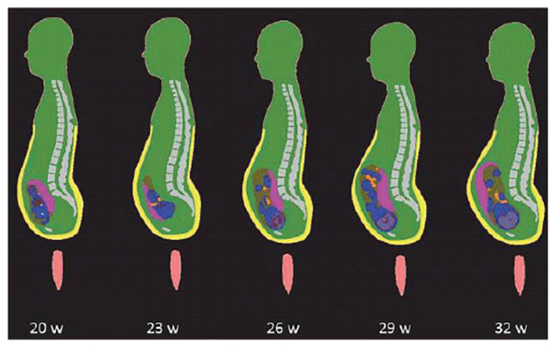
Anatomically-correct fetus positions at different stages of pregnancy [83].
D. Relevant 3D Anatomical Products
Fig. 7 shows a 3D full-body male model from Zygote Media Group, Inc. [94]. This and simlar models are primarily intended for medical illustrations and animations, broadcast television, films, computer games, and educational software. Given a sufficient anatomical accuracy, nothing in principle prevents us from using such models for electromagnetic and other simulations. However, since these types of models are in general not based on real subjects, their applications for regulatory purposes (submitted to the FDA or FCC) might be limited.
Fig. 7.
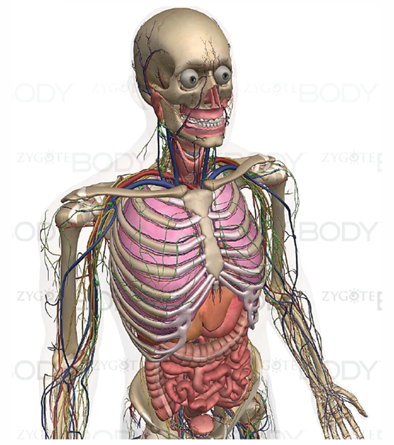
Full-body male model from Zygote Media Group, Inc. [94].
Fig. 8 illustrates the “world distribution” of major detailed virtual human models suitable for electromagnetic safety evaluation and for electromagnetic device design as of 2016-2017. This information is based on Refs. [20],[21] and other sources; it is summarized above in Tables II through IV. The projects performed by the IT’IS Foundation over 2010-2016 [27]–[29] have made them, and a number of the Foundation’s commercial spin-offs, the clear world leaders in the modern regulatory safety- and performance-assessment markets.
Fig. 8.
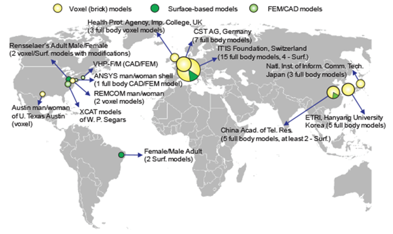
Distribution and origin of major full-body detailed virtual human models applicable for CEM.
III. Human Model Construction. Voxel and CAD Models
It follows from Tables II–IV that the vast majority of the virtual-human models currently available are voxel models and not CAD models. The difference between voxel and CAD models appears to be quite significant. It influences (i) the type of the CEM problems to be solved (resonant or not) and; (ii) the electromagnetic solver type. This difference can be explained best when we review the human model creation process.
A. Human Model Construction. Manual Segmentation
Computational phantoms or virtual humans are created via a set of 3D mathematical algorithms commonly called image segmentation. Segmentation is one of the most studied problems in the field of biomedical image analysis. Consider one body image (a slice in the xy-plane) in Fig. 9a which shows a cross-section of a human leg including the patella [25]. The complete stack of images continues in the z-direction. A skilled operator traces the patella boundary with a set of discrete points in the xy-plane (a polygon) shown by crosses in Fig 9a. A z-coordinate corresponding to the global coordinate system is added. Then, another cross-sectional image is traced, and all 3D points are collected, image by image. The end result is a complete patella boundary in three dimensions given in the form of a point cloud shown in Fig. 9b. This process is known as manual segmentation, still the “gold standard” of image segmentation. Other tissues are segmented similarly. The inner volume of the point cloud is either empty or can be filled with a set of (uniformly distributed) inner nodes. In the latter case, we arrive at a volumetric voxel model of a tissue, which is a typical final result of image segmentation. A large number of such volumes may exist, either interconnected or separate.
Fig. 9.
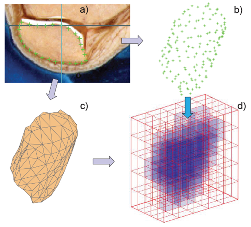
a) – Image of a patella with a traced boundary; b) – resulting point cloud; c) – patella CAD model; d) – patella voxel model.
B. Semi-Automatic Segmentation
Manual segmentation of datasets is extremely labor intensive and expensive. Depending on the images and segmentation quality, this effort is often measured by many man-months or years for a single model [95]. Therefore, most research has focused on semi-automatic or fully automatic approaches. The basic segmentation algorithm is a threshold or pixel contrast method [96], which is similar to manual tracing of the boundaries of 2D object slices outlined above. A more elaborate example is an active contour segmentation technique [97]. For medical image segmentation review, please see [98]–[100]. There is a plethora of image segmentation software packages [101].
A popular and powerful open-source semi-automatic image segmentation tool is ITK-SNAP [98] from University of Pennsylvania, which includes a multi-modality segmentation capability and machine learning to differentiate tissue classes based on texture, location, and intensity.
C. Automatic Cranium Segmentation
A few packages known to the authors that perform automatic segmentation of the cranium MRI data for brain compartments are the open-source FreeSurfer package from Massachusetts General Hospital (MGH) [71]–[75], [102], open-source Oxford’s FSL [103], and CRUISE from the Max Planck Institute for Human and Cognitive Brain Sciences [76]–[81]. Open-source Slicer package [104] is also quite useful. Segmentation of the skull itself may be less straightforward.
As an example, Fig. 10 shows an FEM model with 8 distinct tissues obtained from automatic cranium segmentation via FreeSurfer. The model was (optionally) post-processed in SpaceClaim of ANSYS, Inc. and specifically optimized for fast FEM simulations.
Fig.10.
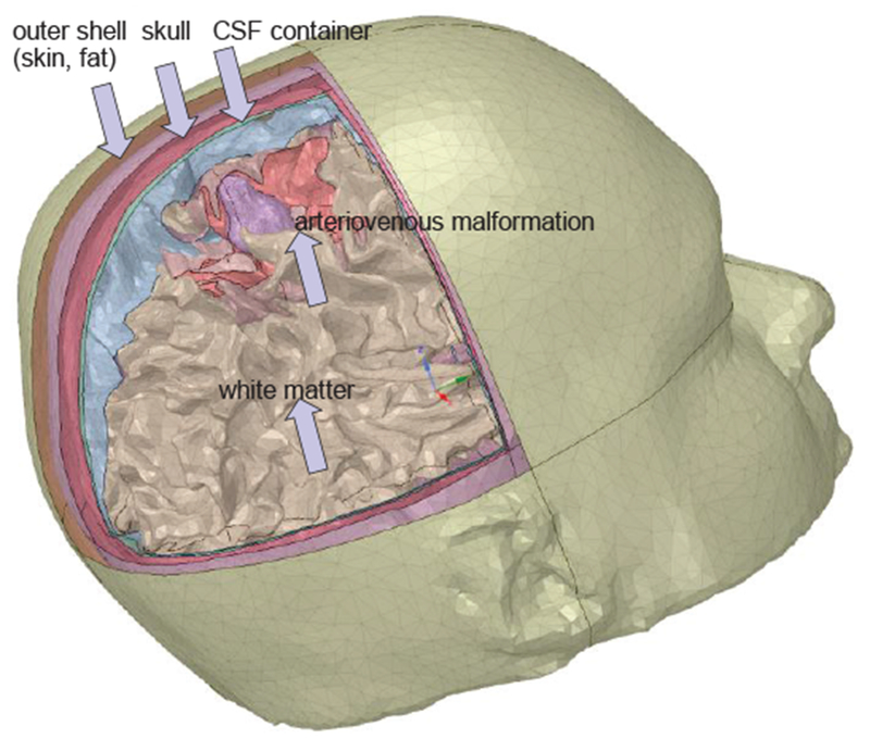
CAD FEM cranium model of a patient with brain pathology obtained via automatic segmentation with FreeSurfer and post-processed in ANSYS SpaceClaim.
D. Automatic Whole Body Segmentation
Efforts have been made to create subject-specific human models via automatic and semi-automatic segmentation. This task is generally very complicated. Fig. 11 shows a USARIEM model, a soldier CAD model (called an anatomy avatar) from the U.S. Army Research Institute of Environmental Medicine (March 2016, [105]). Such models could make an impact on the design of military gear, protective equipment and vehicles, and other applications across military medicine [105].
Fig. 11.
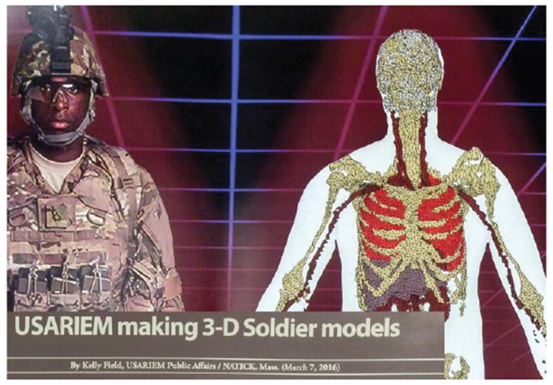
Soldier CAD model from U.S. Army Research Institute of Environmental Medicine (March 2016).
E. Triangular CAD Models
After image segmentation and creation of a point cloud, a surrounding surface may be extracted in the form of a triangular or quadrilateral mesh or a BREP CAD model described below. This operation is called surface extraction or 3D geometry (surface) reconstruction.
In CAD models, which are all suitable for 3D printing (an example is the STL or STereoLithography format), each individual tissue is characterized by its closed surface. In its most common form, the surface is fully described by a set of small adjacent triangles defined through an array of nodes P and an array of triangles t shown in Fig. 9c – a mesh. Every m-th row of array P gives Cartesian coordinates of a nodal point m on the surface, while every n-th row of array t gives three numbers of nodal points forming the n-th triangle. Any observation point inside the triangulated surface is assigned (the same) unique tissue properties. To find the point status (inside/outside), an arbitrary ray emanating from this point is considered. If the point is inside, the number of intersections with the surface is always odd, otherwise it is even. Further, the ray-triangle intersection algorithm is applied [106].
The task of generating a CAD model from the point cloud is illustrated through creating a patella mesh in Fig. 9c from the corresponding point cloud in Fig. 9b. The entire problem in general is quite complex; among the popular methods are the method of marching cubes (marching triangles) [107],[108] and the region-growing ball-pivoting method [109]. The human models shown above in Figs. 1, 3, 5, 10, 11 are all CAD models.
Fig. 5.
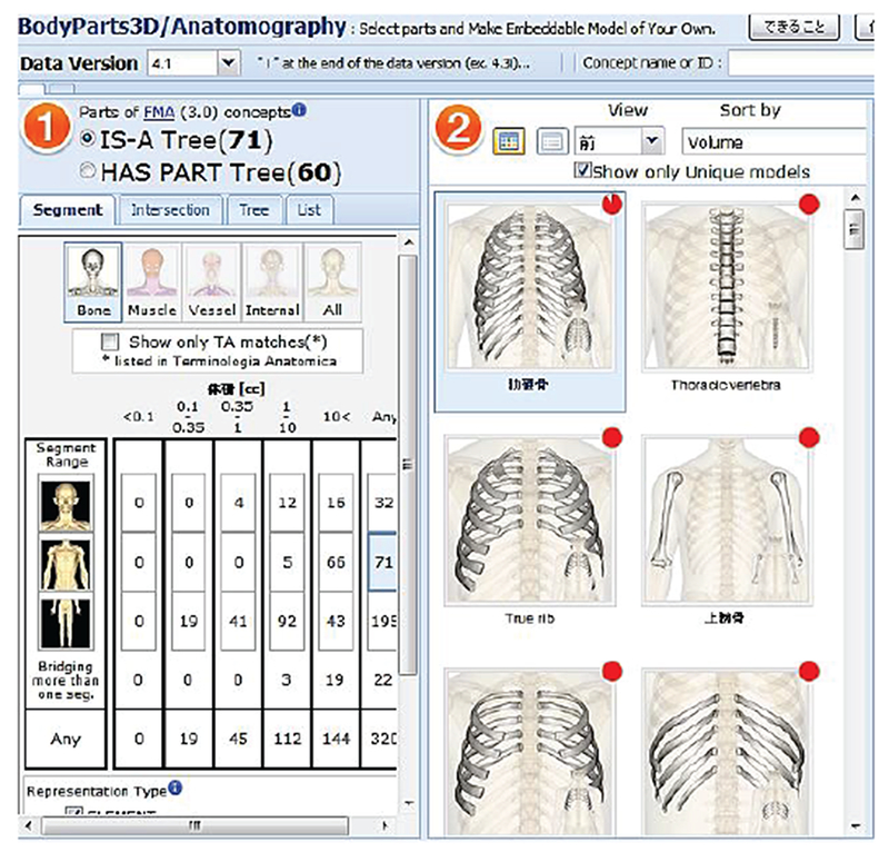
Open-access BodyParts3D online repository [70].
F. Voxel Models
The voxel model directly follows from the segmentation results: given that the point cloud in Fig. 9b is filled with the inner nodes, we can directly arrive on Fig. 9d. Alternatively, the voxel model is straightforwardly constructed from the CAD model. We subdivide the entire 3D space into many small equal brick cells (unit cells) with the size Δx,Δy,Δz shown in Fig. 9d. If the cell center lies within the CAD tissue object in Fig. 9c, the cell is assumed to be a part of the object. Other approaches are also possible. As a result, the entire tissue volume is approximated by a large number of cells seen in Fig. 9d. Every such cell has a unique value for the tissue property (or properties), which is a voxel. Frequently, the entire unit cell along with the assigned tissue properties is designated as a voxel. The voxel model does not have to be constructed from the CAD model. Usually, exactly the opposite is done. In principle, any segmentation result is already the voxel model.
In order to display the staircase surface of a voxel model as a visually smooth boundary, an isosurface or isosurface rendering (a very detailed but often excessive triangular surface mesh) is quickly created. The isosurface algorithm [110],[111] is implemented in many software packages including MATLAB®. The human models shown in Figs. 2, 4, 6 above are voxel models. These voxel models can be and have been converted to large-size surface-based models via isosurface rendering [28],[29],[61].
G. Comparison of CAD and Voxel Models
As of now, the human models with the highest resolution are all static voxel models. Why is it so? This is due to the fact that voxel-based models naturally represent highly-inhomogeneous inter-tissue regions and can replicate these tissues exactly as they appear in the source images. The 3D CAD model of a multi-tissue body (or even of a single tissue) is much more difficult to construct. Furthermore, detailed triangulated human models with a very large number of triangles in excess of 1-5×10⁶ [28], [61] may require extremely large FEM meshing times (creating a volumetric tetrahedral mesh) and quite large FEM (or BEM, MoM) simulation times, which could make their use prohibitive for a number of optimization tasks. In particular, in ANSYS Electronics Desktop, the meshing time can be 10–100 times greater than the simulation time for low-quality surface shell meshes. Therefore, the CAD models tend to be significantly less accurate in general despite their clear mathematical advantage which is a linear (in case of triangles or plane quadrilaterals) or polynomial (in case of a spline representation) surface approximation in contrast to the staircase approximation of the voxel grid. For voxel models, the segmentation accuracy, which is the deviation from the true surface along the normal direction, is equal to the size of the unit cell.
However, the CAD model is inherently deformable (cf. [46]–[52],[112]) including both free-form deformations and affine transformations, while the voxel model is essentially “cast in stone”. Although very realistic, modern voxelized phantoms, based upon direct image segmentation, have the disadvantage of being inflexible. The resolution is fixed, and it is difficult to model variations in anatomy, patient positioning, or motion. Last but not least, the CAD model is fully compatible with the standard FEM analysis on unstructured grids and 3D printing while the voxel model is not.
H. Specific Conditions for CAD Models
The following two conditions are required for a true CAD human body model: (1) a 3D triangular mesh representing a solid object must not have holes; (2) the surface of a well-behaved triangular mesh in 3D must satisfy one critical condition, which is the so-called manifold condition. A mesh is 2-manifold if every node of the mesh has a disk-shaped neighborhood of triangles. This neighborhood can be continuously deformed to an open disk. Every edge of a 2-manifold mesh is a manifold edge with only two attached triangles. All other meshes are non-manifold meshes and are not suitable for FEM analysis. Fig. 12 gives examples of a manifold edge, a non-manifold edge and, a non-manifold mesh with a non-manifold node.
Fig. 12.

a) – Examples of a manifold edge; b) – non-manifold edge, and c) – non-manifold node.
I. Contact regions
Constructing a multi-tissue voxel model is straightforward. Different cells are simply assigned different tissue properties. Construction of a multi-tissue CAD model is more difficult. First, different tissue meshes must not intersect, though fully-enclosed meshes are still allowed. Another well-known problem with multi-object models is object matching in a contact region. Usually, the contact region is not explicitly defined in a CAD model, so that it has to be discovered separately by testing for face-to-face overlaps and matching CAD faces/edges in the contact region [113]. This circumstance may create problems for certain CAD kernels such as ACIS. In order to prevent CAD import errors, a thin gap can be introduced between different tissue objects filled with “average body properties” of an outer enclosing shell. In some sense, this gap has the physical meaning of a membrane separating different tissues. If the gap is reasonably small it provides a close approximation to reality for different physical processes. However, for a number of purposes, the gaps may not be acceptable.
J. Mesh Processing Tools and CAD Model Construction
Many free and commercial mesh processing tools exist. MeshLab of the Italian National Research Council and Univ.of Pisa [114]. ParaView of Sandia National Laboratories [115], GMV of Los Alamos National Laboratory [116], and CGAL [117] are all open–source mesh tools. An excellent commeercial mesh processing tool capable of mesh healing and separation of multiple surface objects is ANSYS SpaceClaim®.
Generation of a CAD model may start with a point cloud as shown in Fig. 9b or with a voxel model. A very detailed triangular isosurface mesh described above is created first. Then, mesh decimation [118], smoothing [119]–[125], and intersection resolution [126]–[132] processes are applied, often interchangeably. When a thin gap between individual objects is allowed, the shallow intersections between the nearby objects may be resolved via deforming individual meshes in the contact area in the inner normal directions.
K. NURBS or BREP Representation
Another approach common in manufacturing and computer graphics is the subdivision of the original surface into a smaller number of relatively-large curved spline surfaces – NURBS (Non-uniform Rational Bézier Spline surfaces) or B-splines [132], which are common in manufacturing and computer graphics. As an example, Fig. 13 shows a conversion of the original triangulated skin shell surface with about 7,000 triangles to a set of NURB surfaces (~60 B-splines) done via SpaceClaim of ANSYS. NURB surfaces enable refined meshes without sharp edges in specific areas of interest, i.e. adaptive surface refinement.
Fig. 13.
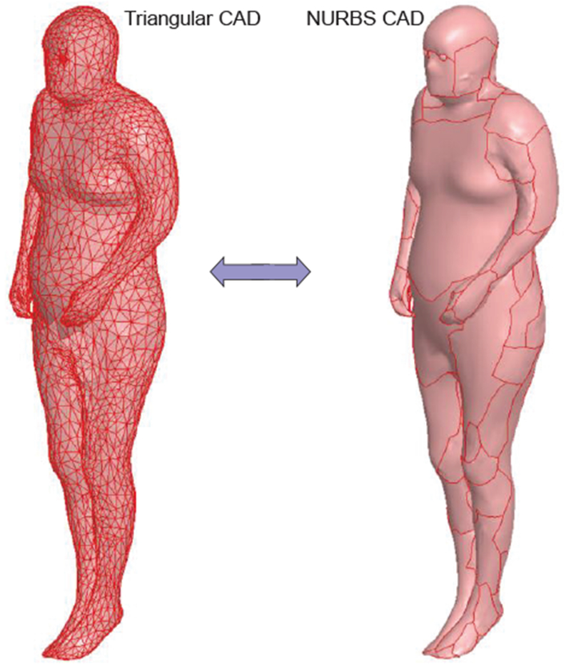
Left – initial triangular surface of a human model; Right – the same surface converted to NLTRBS (B-splines).
Furthermore, the NURBS are ideal for deformation purposes. Unfortunately at present, the NURB surfaces have a rather limited value for an FEM/MoM solver, which internally operates with geometry primitives, triangular/quadrilateral facets and tetrahedra. A double conversion, extracted triangular surfaces →NURBS →FEM triangular surfaces, may require potentially significant additional meshing times.
A pipeline for multi-modality deformable NURBS-based human models is being developed by Dr. W. Segars and his coworkers at Duke University, USA [48]–[52]. To change the anatomy, one has to apply transforms (rigid or non-rigid) to the surfaces. The 4D XCAT phantom was developed by this group as a computational model of the human anatomy and physiology primarily for use in medical imaging research. Starting with two detailed whole-body adult male and female anatomies, based upon the Visible Human Project anatomical datasets from the National Library of Medicine, the XCAT has been expanded into a population of models representing the human body of varying ages, heights, and weights from newborn to adult.
IV. Material Properties
A. Isotropic Electromagnetic Tissue Properties
Every human model must be augmented with electrical, mechanical and thermal tissue properties for further use. In the isotropic case, the electromagnetic material properties usually include scalar relative permittivity and scalar conductivity of a tissue, both as functions of frequency. The pioneering work of C. Gabriel and colleagues from UK [133]–[136], supported by the US Air Force Research Laboratory and their latest results [137], reported the corresponding data from 10 Hz to 100 GHz for the bulk of tissues. Most of the measurements performed were on animal tissues carried out in-vitro. Measurements were also made, in-vivo, on accessible parts of the human body such as palm, sole and forearm skin, tongue, etc. This data is considered standard and has been replicated in the IT’IS (Zurich, Switzerland) database for electromagnetic parameters [138]. Wagner et al [139] recently measured in-vivo impedances of human cranial tissues (skull, grey matter, white matter) from 10 Hz to 50 kHz.
B. Anisotropic Tissue Models. Tensorial Approach
Many tissues such as the brain and the spinal cord of the central nervous system, the peripheral nervous system, and muscles including the heart, are fibrous in nature. Isotropic human models that assume homogeneous volumes for every individual tissue cannot resolve this fine structure. Instead, conductivity and permittivity tensors may be considered, which characterize the fibrous structure in an average sense. In the local coordinate system, the permittivity and conductivity tensors are strictly diagonal. Yet, for a numerical simulation, a global coordinate system must be chosen.
The approach is thus to consider a CAD or voxel human tissue augmented with the anisotropic conductivity/permittivity tensors. Anisotropic muscle tissue models have been developed in [140]–[143] and in application to the voxel grid in [142],[143]. In particular, an anisotropic ratio of 10 for both conductivity and permittivity over the audio frequency range (20 Hz–20 kHz) has been observed [143]. For an anisotropic arm model in COMSOL, please refer to [144].
Effective-medium brain modeling based on the anisitropic conductivity tensor is under active investigation by a group of researchers from the Swiss Federal Institute of Technology (ETH) [145]–[147], [61]. The concept is to utilize a shell tissue model (e.g., the grey matter), but with an anisotropic material inside.
C. Fiber Models
Diffusion MRI allows for the determination of the anisotropy of water diffusion in the human tissue (e.g., the brain) non-invasively and has numerous applications including reconstruction of the major white matter pathways (for a review, see [148]). As an example, Fig. 14 shows a fiber connectivity map (or connectome) of white matter where different colors indicate different fiber directions. The number of fibers in the map may be on the order of 100,000. The fiber network may replace the entire white matter shell.
Fig. 14.
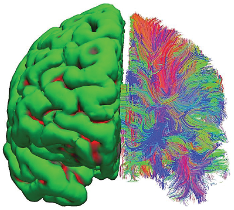
Surface-based vs. neural-fiber model of white matter. A set of in-vivo diffusion MRI images from Connectome Project [75] has been processed via FreeSurfer software [74], [102]. Left hemisphere – surface-based homogeneous model; right hemisphere – fiber model. Different colors indicate dominant fiber directions: red-vert.; green-horizontal; blue-into the page.
In the effective-medium approach discussed above, the electrical conductivity tensor of tissue is derived from the diffusion tensor measured by MRI [149]. Such a method is not without its limitations. The basic tensor model is not capable of accurately capturing the more complex fiber geometries such as intravoxel crossings (or fiber crossings) [150]. For this purpose, more general methods [151],[152] have been developed. Furthermore, numerical modeling of individual fibers [153],[154] is possible and might offer more insight into the realistic fibrous structures.
The fibers in Fig. 14-right are not individual axons but they are tractrographic reconstruction of white matter tracts or bundles of actual nerve fiber containing multiple axons, each of which has a cross-section on the order of micrometers, that are computationally generated based on local diffusion orientation information. An analog to such a fiber bundle is a thick electric cable consisting of multiple thin conductors. In any case, this is the most accurate representation of brain connectivity obtained non-invasively in vivo to date, with the best voxel resolution of about 1 mm. Ongoing progress in diffusion MRI [71]–[73], [75], [155],[156] continuously pushes this limit.
V. Computational Electromagnetics Software for Working with Virtual Humans
The type of electromagnetic, thermal or mechanical stress analysis software used depends on the human model availability; e.g. voxel or CAD.
A. Finite-Difference Method for Voxel Models
Voxel-based models are primarily suitable for finite-difference (FD) methods [157] on uniform rectangular grids at low frequencies and for the finite-difference time-domain (FDTD) method on uniform rectangular grids at high frequencies [157]–[159]. The latter option assumes that the entire solution is computed in the time domain. The finite integration technique (FIT) of T. Weiland [160],[161] used by the time-domain electromagnetic solver of CST AG is reduced to the standard FDTD on a uniform rectangular grid as shown in Fig. 15a. Simultaneously, it expands the FDTD method to tetrahedral grids as shown in Fig. 15b. At present, grids with a few billions unit cells can be processed. The FDTD method is currently the major tool for high-frequency electromagnetic simulations with computational human models.
Fig. 15.
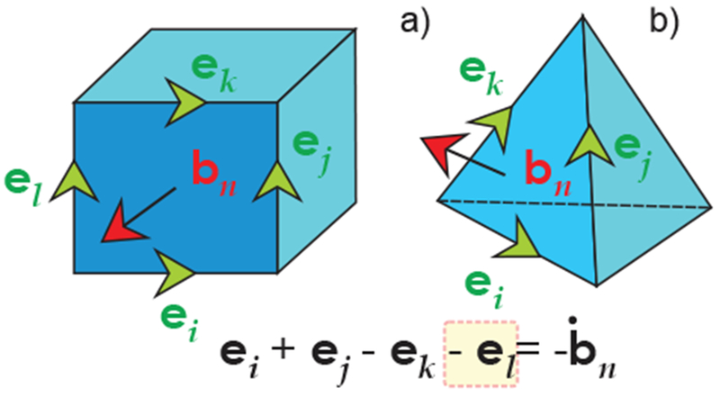
a) – Using FIT to discretize Faraday’s equation for a brick (similar to the FDTD Yee cell); b) – using FIT for a tetrahedral mesh.
B. Subgridding Techniques in Finite-Difference Methods
Subgridding techniques allow us to vary the FDTD mesh size in specific domains of interest [159],[162], which is a very significant advantage as compared to the standard uniform finite differences. Recall that one major “flaw” of the standard voxel models experienced by many users dealing with human models is the inability to selectively refine the grid. Indeed, the resolution of the voxel model should be equal to the finest grid resolution. For example, a time-domain version of the transmission-line matrix method (TLM) [163],[164] implemented in CST Studio Suite® uses a multi-grid formulation. The uniform mesh is first refined or graded to capture detail in the geometry. Small mesh cells are subsequently automatically combined or “lumped”, with the level of lumping increasing with distance from geometric boundaries. This process removes any “bleeding” in the mesh, minimizing the cell count and reducing computational requirements to the absolute minimum. The end result is a multi-level octree mesh. In many cases, the total number of mesh cells is reduced by over 90%.
C. Finite Element Method (FEM) for CAD Models. Frequency-Domain Solution
A CAD-based human model is suitable for both the finite-difference method (after a trivial voxelization) and the finite element method. The FEM for electromagnetic simulations is used by ANSYS Electronics Desktop (both HFSS and Maxwell), CST Studio Suite, COMSOL, and Abaqus. The FEM method typically employs vector basis functions on tetrahedral [165]–[168], first described by Nédélec [168]. An advantage of the FEM is a powerful adaptive mesh refinement procedure implemented in ANSYS Electronics Desktop and CST Studio Suite. This enables tetrahedral mesh optimization such that the simulation may be handled accurately while significantly reducing computational runtime.
For radio wave propagation, the FEM method has been primarily used in the frequency domain (after converting all quantities to phasors). The frequency domain solution allows us to better resolve resonances. The frequency domain FEM method (and potentially any frequency domain method) may significantly outperform FDTD computations for MRI-related research [169]. The use of unstructured meshes, combined with automatic mesh adaptation in the frequency domain has been instrumental in delivering accurate results for complicated geometries.
D. Which Method to Choose?
Traditionally, it was difficult to implement finite element methods in time domain, i.e., for a broadband system response. Recent advances in finite element techniques have led to a new scheme based on the discontinuous Galerkin family of numerical methods [170]–[173]. This scheme retains the flexibility, accuracy and reliability of unstructured mesh finite element methods but avoids the solution of a large matrix equation at each time step. Instead, each mesh element advances in time using its own time step in a synchronous manner. This results in a significant speed-up on unstructured meshes, as the largest mesh elements typically utilize time steps that are two to five orders of magnitude larger than those of the smallest mesh elements. The corresponding scheme is now implemented in ANSYS Electronics Desktop.
On the other hand, the time-domain methods have been traditionally associated with uniform structured meshes (rectangular grids) without an ability to adaptively refine (or coarsen) the mesh. However, the FIT technique outlined in Fig. 15b may now handle general tetrahedral or hexahedral meshes, and may be regarded as a variation of the FEM. Also, the subgridding techniques are able to at least partially overcome the mesh refinement difficulty.
E. Boundary Element Method (BEM) or Method of Moments (MoM)
The boundary element method [157], [174]–[179] does not require special boundary conditions typical for FDTD and FEM; it is simple and versatile [179]. However, this method operates with dense matrices and requires matrix inversion. Therefore, it is less common in applications to human models. Specific applications have been developed for the cranium. In the field of electromagnetic brain mapping, the simple and robust BEM method has been widely adopted for MEG/EEG source localization applications (see Section IX). The BEM approach has been shown to improve the computational targeting of Transcranial Magnetic Stimulation (TMS) [180] in comparison with spherical models; it has also been employed in large-scale empirical studies to quantify the TMS electric field distribution “hot spots” across subjects [181]. The BEM approach has been employed to estimate the efficacy of TMS on stimulating the fiber bundles projecting from cortex [182] and to computationally determine the optimal coil location to stimulate a pre-determined fiber bundle. MoM volume integrals have recently been reviewed for accurate analysis of antennas near/on/in human models [183]. MoM (BEM) can be applied to fiber models using a one-dimensional model along the fiber.
Recent advantages in the fast and iterative MoM (BEM) solvers (see, for example [184]–[187]) may lead to a more widespread use of these methods.
F. Typical Computational Times and Expected Accuracy
One benchmark example in electromagnetics is the scattering problem with plane wave incidence at, say, 300 MHz shown in Fig. 16. The incident wave polarization is vertical. As an example, the full-body CAD VHP-Female BASE model with about 180 individual tissue parts was simulated simultaneously in ANSYS HFSS and CST Studio Suite frequency-domain solver [56]. Table V shows the corresponding simulation times in ANSYS for different server configurations [54].
Fig. 16.
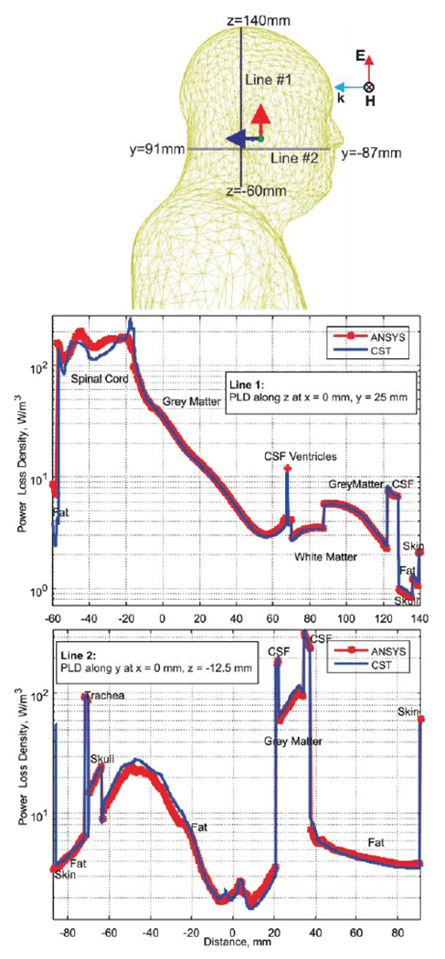
Paths within the body chosen for power loss density evaluation and power loss density along line segments.
Table V.
Simulation Benchmarks for Plane Wave Test (circa 2015-2016).
| Execution parameters for four representative servers | ||
|---|---|---|
| System | Tetrahedral mesh size & total RAM (start/stop) | Execution time for 5 passes |
| System #1 (one task, one core) | ||
| Intel(R) Xeon(R) CPU E5-2697 V2, 256 GB. 64-bit OS Windows Server 2008 R2 Enterprise. ANSYS EM Suite® 16 |
450,000/1,000,000 2.6GB/87 GB |
Meshing time: 50 min Sim. time: 10 hr 48 min |
| System #2 (one task, one core) | ||
| 4 AMD OPTERON 6174 12 core processors, 192 GB, 64-bit OS, Windows Server 2008 R2 Enterprise, ANSYS EM Suite® 15 | 450,000/1,000,000 2.0GB/115 GB |
Meshing time: 70 min Sim. time: 28 hr 55 min |
| System #3 (one task, one core) | ||
| Intel(R) Xeon(R) CPU E5-2690, 192 GB, 64-bit OS Red Hat Enterprise Linux 2.6.32, ANSYS EM Suite® 15 | 450,000/1,000,000 2.0 GB/87 GB |
Meshing time: 63 min Sim. time: 10 hr 40 min |
| System #4 (one task, eight cores, HPC option) a | ||
| Intel(R) Xeon(R) CPU E5-2697 V2, 256 GB. 64-bit OS Windows Server 2008 R2 Enterprise, ANSYS EM Suite® 16 |
450,000/1,000,000 2.6GB/87 GB |
Meshing time: 50 min Sim. time: 2 hr 43 min |
Systems 1 and 4 differ by the HPC option only.
CST Studio Suite simulation times are quite similar. For a quantitative comparison between different simulation methods, we have evaluated the volume power loss density in W/m3 along certain paths within the body. Those paths are two line segments shown in Fig. 16. The volume power loss density is given by where σ(r) is the local tissue conductivity. It is computed for the total electric field in the phasor form, E(r), which is the scattered field plus the incident field.
Fig. 16 shows results of the CST Studio Suite and ANSYS HFSS simulations for this particular problem. Although a general agreement is excellent; certain deviations may be observed and partially explained by the use of different averaging methods for the power loss density.
VI. Human Model Validation
A. MRI RF Coil Test
There is no generally accepted routine to justify the numerical (as well anatomical) accuracy of a virtual human model for a broad application range. A logical and common test today, supported by the FDA, includes specific absorption rate (SAR) computations in an RF MRI transmit coil.
For example, when very sharp peaks of the specific absorption rate are observed, this is often an indication of a “flaw” in the human model in a certain anatomical region. The flaw may be due to isolated pieces of one tissue within another and/or by fragmented tissues (the voxel model). The flaw may be also given by low-quality or very large triangles, sharp bends and small gaps, as well as sharp contact angles (for the CAD model). Adaptive mesh refinement is a way to make sure that observed “flaws” (if any) are not due to coarse meshing (large triangles). However, it cannot generally validate the human model. As an example, consider Fig. 17 which shows the local SAR distribution for a full-body birdcage coil with all ports driven and loaded with the VHP-Female v. 3.0 model [55],[56] at 1 W input power in the coronal plane at 63.87 MHz (1.5 T field). There are some noticeable differences in the solution when using one versus eight adaptive mesh refinement passes. For example, hot spots at the top of the head disappear.
Fig. 17.
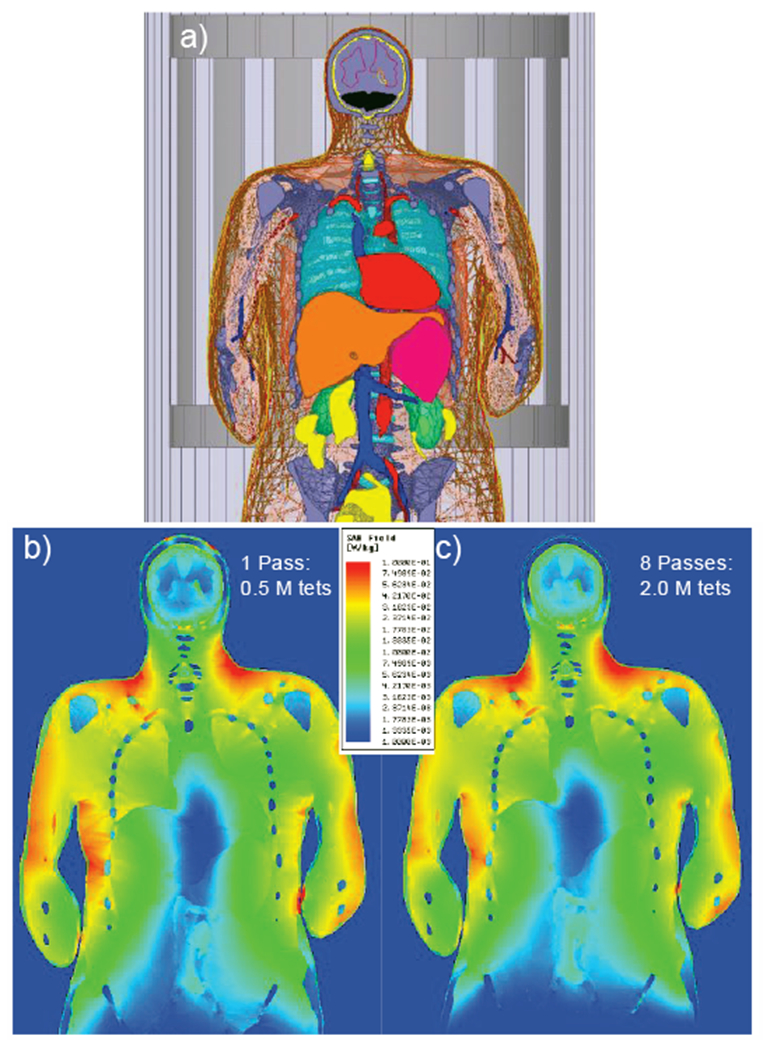
Local SAR distribution for a coil loaded with the VHP-Female v. 3.0 model [55],[56] at 1 W input power in the coronal plane at 63.87 MHz. a) – Landmark of model inside the birdcage; b) – solution with one adaptive pass; c) – solution with eight adaptive passes.
B. SAR Margins
The local SAR (W/kg) is defined by averaging the dissipated power per unit mass over a small (ideally infinitesimally small) volume V, that is
| (1) |
Here, σ(r) is the local tissue conductivity, ρ(r) is the local mass density, and |E(r)| is the electric field magnitude at an observation point. The body-averaged or the whole-body (global-body) SARbody is given by averaging the local SAR over the entire body volume, as
| (2) |
Similarly, SAR1g is given by averaging over a contiguous volume with the weight of 1 g
| (3) |
SAR10g(r) is found in the same fashion.
The SAR values vary with the applied RF source strength. We often normalize the fields solutions given the desired magnitude of field at the coil center of 1 μT. The normalization is done in the form
| (4) |
Some recent reference data on SAR comptutations for human models are given in Refs. [188]–[196], [16]. Table VI presents the bulk of this data. Although the SAR data vary widely, we may still observe the following margins (all data in W/kg) for
the heart, shoulder, abdominal, and pelvic landmarks;
different human models;
different RF coil types, and for 1.5 T and 3 T fields, respectively,
based on Table VI and other sources:
| (5) |
| (6) |
| (7) |
Table VI.
Computed SAR values from different sources (W/kg) given 1 μT field (at the coil isocenter).
| Ref # | Method | Model | Coil landmark | Whole-body SAR Eq. (2) | Max. non-averaged local SAR Eq.(1) | Max. 1g local SAR Eq. (3) | Max. 10g local SAR Eq. (3) |
|---|---|---|---|---|---|---|---|
| Ref. [189] | FDTD 5 mm voxel | Voxel Vis. Human Male 122kg [189], 128 MHz | Abdominal | 0.58 | 22.78 | 11.90 | 8.79 |
| Ref. [189] | FDTD 3.5 mm voxel | Voxel Vis. Human Male 122 kg [189], 128 MHz | Abdominal | 0.57 | 24.91 | 11.63 | 6.98 |
| Ref. [189] | FDTD 2.5 mm voxel | Voxel Vis. Human Male 122 kg [189], 128 MHz | Abdominal | 0.54 | 35.68 | 13.76 | 8.88 |
| Ref. [193] | FDTD 3 mm voxel | Voxel Vis. Human Female 128 MHz | Heart | Normalized to 0.15 (present report) | NA | 2.46-4.11 Varies with coil type |
1.23-2.03 Varies with coil type |
| Ref. [193] | FDTD 3 mm voxel | Voxel Vis. Human Male 128 MHz | Pelvic | Normalized to 0.54 (Ref. [189]) | NA | 8.91-14.8 Varies with coil type |
4.21-6.86 Varies with coil type |
| Ref. [194] | FDTD Voxel size unknown | Voxel Vis. Human Female, 64 MHz | Heart | Normalized to 0.15 (author’s study) | NA | NA | 3.35 |
| Ref. [195] | FDTD Voxel size 2mm | Voxel Nagaoka Female 64 MHz | Abdominal | 0.13 | NA | 3.2 | 2.1 |
| Ref. [195] | FDTD Voxel size 2mm | Voxel Vis. Human Male 122 kg 64 MHz | Abdominal | 0.18 | NA | 3.6 | 2.4 |
| Ref. [195] | FDTD Voxel size 2mm | Voxel Nagaoka Female 128 MHz | Abdominal | 0.24 | NA | 5.3 | 3.9 |
| Ref. [195] | FDTD Voxel size 2mm | Voxel Vis. Human Male 122 kg 128 MHz | Abdominal | 0.31 | NA | 5.2 | 3.9 |
| Authors’ study | FEM 8 adaptive passes (ANSYS) | CAD VHP-Female 3.0 [55],[56] 88 kg, 64 MHz | Shoulder/heart (top of vert. T7) | 0.15 | 12.0 | 3.05 | 1.37 |
More differentiated estimates, which are specifically based on body mass and body mass index (BMI), could be obtained. Thus, for a human model under test, we could compute three parameters: SARbody, and . Once these values are within the established margins, the model passes a very basic SAR test.
VII. Low and High Frequency Simulation Tasks
A. When can a Low-Frequency (Quasistatic) Approximation be Applied?
One critical parameter that sets a distinct operational region for an electromagnetic solver as applied to a human body is the skin layer depth,
| (8) |
where ω is the angular frequency, μ = 4π × 10−7H/m is the magnetic permeability of vacuum (body), and σ is the tissue conductivity in S/m. In contrast to metals, human tissues have a conductivity that is six to seven orders of magnitude smaller. Therefore the skin depth may be large as compared to the tissue or body size, even at relatively high frequencies, which is known as the thin limit condition. This literally means that the (secondary or internal) magnetic field of body currents is also small as compared to the known external large magnetic field in Faraday’s law of induction. Such an approximation leads to the Poisson equation for the electric potential of eddy currents, similar to the Poisson equations used in electrostatics [179]. As an example, the skin depth at 1 MHz and σ = 0.15 S/m is about 1.3 m (i.e., considerably larger than the size of the head), which makes it possible to consider a wireless link between two ears even at 1 MHz as an approximately quasistatic problem with a sufficient degree of accuracy. The quasistatic approach is widely used in particular for modeling cancer-treating RF fields [67],[197],[198].
B. Contribution of Displacement Currents
Another critical parameter is the charge relaxation time, τ = ε/σ, where ε is tissue’s electric permittivity. The well-known quasistatic condition,
| (9) |
allows us to neglect displacement currents in Ampere’s law as compared to the conduction currents. Due to the very high dielectric tissue constants, especially at low frequencies [133]–[139], Eq. (9) is often barely satisfied. For example, in a muscle tissue at 1 MHz, εω/σ = 0.2. Therefore, the displacement currents may need to be taken into account both in high- and low-frequency limits.
For the quasistatic approximation in frequency domain, this task is trivially accomplished by using complex conductivity, σ → σ + jωϵ = σ + jωε0εr. Fig. 18 shows relative contributions of displacement and conduction currents,
| (10) |
to the total current density, J, in some common tissues including cortical and cancellous bone. Both of these tissue currents very significantly dominate the displacement current in vacuum, also shown in Fig. 18 by a blue line, in the frequency band up to 1 GHz.
Fig. 18.
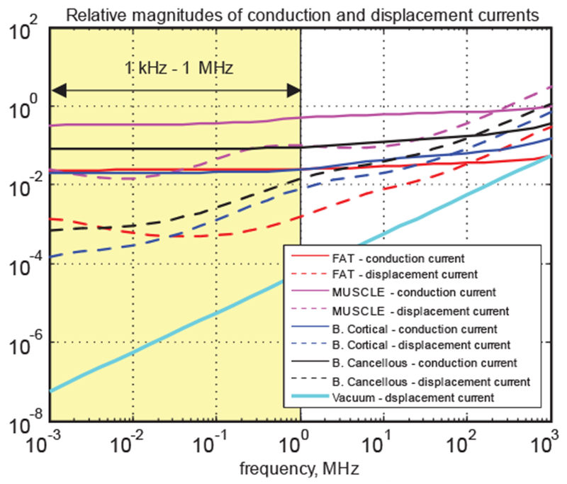
Relative magnitudes of conduction and displacement currents in common tissues.
VIII. Modern High Frequency Applications
A. Body Area Networks (BANs)
As wearable and implantable devices connected to the Internet or to each other multiply (as the Internet of Things becomes pervasive), individuals are quickly developing into complex body-area networks (BANs). Fig. 19 shows a sketch of a BAN communication for two different human models derived from the Visible Human Project® of the U.S. National Library of Medicine [22]–[26].
Fig. 19.
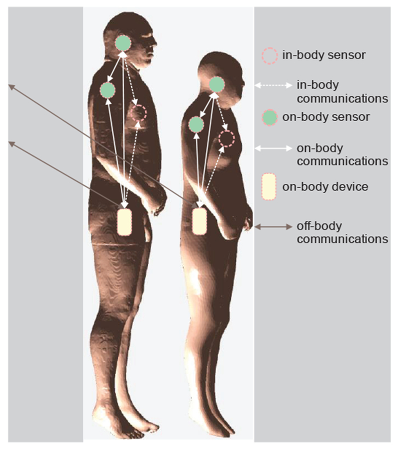
An overview of a BAN communication. Note change in the network topology depending on body composition.
It is extremely difficult to test all such possible configurations, and it is also challenging to obtain FDA or FCC approval for each new device. Therefore, market leaders use engineering simulation to model both the device and the human body, while also considering performance and safety metrics with different body types (male, female, child, slim, average, overweight, etc.) [199].
The IEEE 802.15.6 standard is the latest international standard for Wireless Body Area Networks (WBANs). WBANs supports a variety of real-time health monitoring and consumer electronics applications [200]–[203]. Various communication bands are dispersed between 400 MHz to 2.4 GHz and beyond, including Medical Body Area Network (MBAN) spectrum of 2360 to 2400 MHz. Table VII lists major scenarios [204].
Table VII.
List of Scenarios and Their Description for IEEE 802.15.6 Standard (after [204]).
| Scenario | Description | Frequency band | Channel Model |
|---|---|---|---|
| S1 | Implant to Implant | 402–405 MHz | CM1 |
| S2 | Implant to body surface | 402–405 MHz | CM2 |
| S3 | Implant to external | 402–405 MHz | CM2 |
| S4 | Body surface to body surface (LOS) | 13.5, 50, 400, 600, 900 MHz 2.4, 3.1–10.6 GHz | CM3 |
| S5 | Body surface to body surface (NLOS) | 13.5, 50, 400, 600, 900 MHz 2.4, 3.1–10.6 GHz | CM3 |
| S6 | Body surface to external (LOS) | 900 MHz 2.4, 3.1–10.6 GHz | CM4 |
| S7 | Body surface to external (NLOS) | 900 MHz 2.4, 3.1–10.6 GHz | CM4 |
B. Value of Virtual Human Model for BAN
For off-body communications related to indoor geolocation, the detailed human model is often unnecessary, since both the transmitter and the receiver are typically located far away from the body. Simplified models in the form of a homogeneous shell [205] or geometry primitives (cylinders) have been used. For all other types of BAN, some sort of a detailed human model is necessary; this need has been recognized since approximately 2007 [206],[207]. It is believed that an otherwise homogeneous human model with several shells (skin, fat, average body) may be sufficient for a number of tasks. This simplification has been confirmed by MRI-related studies [189].
C. Challenge of on-Body and In-Body Antenna Design: Shorting out Antenna Near-Field
Design of a small and efficient on-body antenna for WBAN applications is difficult. One well-known problem is illustrated in Fig. 20. Here, we use a distributed-circuit approach (or the 3-D impedance method [208]–[213]) and replace a tissue by a distributed network of capacitances, resistances, and possibly inductances. Note that smaller distributed inductances may be ignored in the near field of the antenna and/or at lower frequencies. A dipole antenna is considered for three different configurations: on the body surface, within the body, and within the body but isolated inside a container.
Fig. 20.
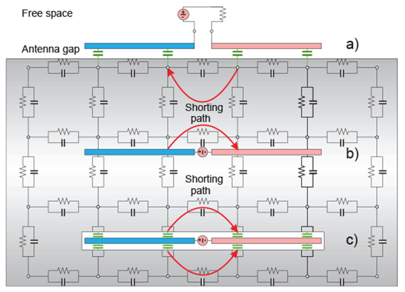
Antenna behavior in a lossy tissue with a high value of dielectric constant and high conductivity. Coupling capacitances are marked green.
For an on-body antenna located very close to the skin surface in Fig. 20a, the coupling capacitance to the body (marked green in Fig. 20a) may be significant. As a result, the antenna is partially shorted out directly at the antenna feed. Instead of flowing along the entire antenna length, a significant portion of the antenna current will flow directly through the lossy body. Thus, the antenna design will likely predict a wide impedance bandwidth (due to the losses), but a very low antenna efficiency. The antenna literally becomes a heater and not a radiator.
The effect of the body on the antenna is in fact twofold. The capacitive (non-lossy) displacement current flowing through the body leads to the strong antenna mismatch but does not generally decrease efficiency. Such a mismatch can be mitigated by a proper antenna design. The conduction current, on the other hand, directly contributes to the power loss but “improves” antenna matching. For the non-isolated in-body antenna in Fig. 20b, the situation potentially becomes even worse since a direct ohmic contact with a conducting tissue further facilitates shorting out the antenna feed. The impedance bandwidth is expected to be large but the efficiency is very low.
Even the isolated antenna in Fig. 20c may experience a strong capacitive coupling with the surrounding tissue when the enclosing container has a very small thickness. However, in many cases, the container size cannot be significantly increased as seen in Fig. 21 [214],[215].
Fig. 21.
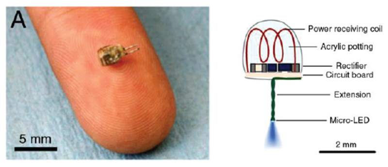
An energy-harvesting in-body coil antenna for a micro-implant in the low-gigahertz range (1.6 GHz) [214],[215].
D. Challenge of on-Body and In-Body Antenna Design: Creeping and Surface Waves
Creeping wave around the body is a part of the full-wave diffraction problem solution [216]–[219]. The creeping wave exists for a perfectly conducting object where the classic surface waves are impossible. Thus, the creeping wave may or may not include the true surface waves.
Trapped surface wave was originally discovered for a grounded dielectric slab [220],[221].
Zenneck surface wave exists at the boundary between conducting and non-conducting media [222]–[229]. It is very difficult to excite a Zenneck wave due to its large extend in the transversal direction. However, a combination of both surface waves [230],[231] may exist and be probably well localized at the air/fat/muscle interface.
Quite often, creeping/surface waves work to our advantage and enable NLOS (non-line-of-sight) communications between different body parts [217], [232]–[234].
E. On-Body Antenna Design
On-body antenna design has been a tremendous field of research. The bulk of the effort has been geared toward wireless communication antennas which must radiate from the body surface to air (cf. [235]–[241]). In a number of cases, on-body antennas are communicating with implants or smart pills [242]–[249], [214],[215]. Dedicated antennas for microwave tomography (for radiating into the body) have been broadband monopoles/dipoles [250]–[260] including their modern printed versions [261]–[263] as well as small-size arrays [248]–[261], [264],[265]. Recently, wideband and multiband (slotted) patch antennas have been suggested and investigated [265]–[270]. Emphasis is usually on the (ultra)wideband performance.
As an example, Fig. 22 shows cloth-mounted antenna design performed by CST AG [271] with the VHP-Female CAD model (the second last row in Table II). Differences in volume power loss density or PLD between homogeneous (a) and inhomogeneous (b) models are clearly seen.
Fig. 22.
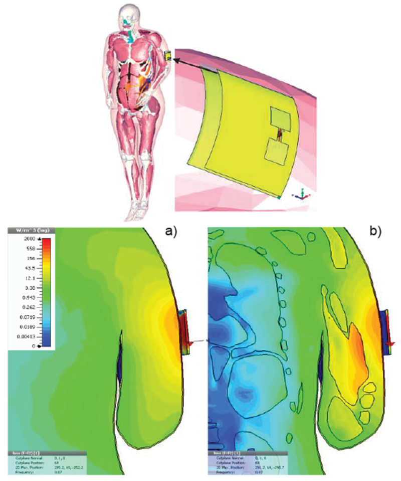
Volume power loss density in W/m3 for cloth-mounted antenna design at 870 MHz [271]. a)- Homogeneous body model; b) – inhomogeneous model.
As another example, Fig. 23 illustrates antenna performance in MICS (Medical Implant Communications Service) band in proximity to varying body types/sizes using the same VHP-Female CAD model in ANSYS HFSS [272]. MICS is an earlier version of the Medical Device Radiocommunications Service (MedRadio) covering 401–406, 413–419, 426–432, 438–444, and 451–457 MHz bands. Creeping waves around the body are clearly seen in Fig. 23.
Fig. 23.
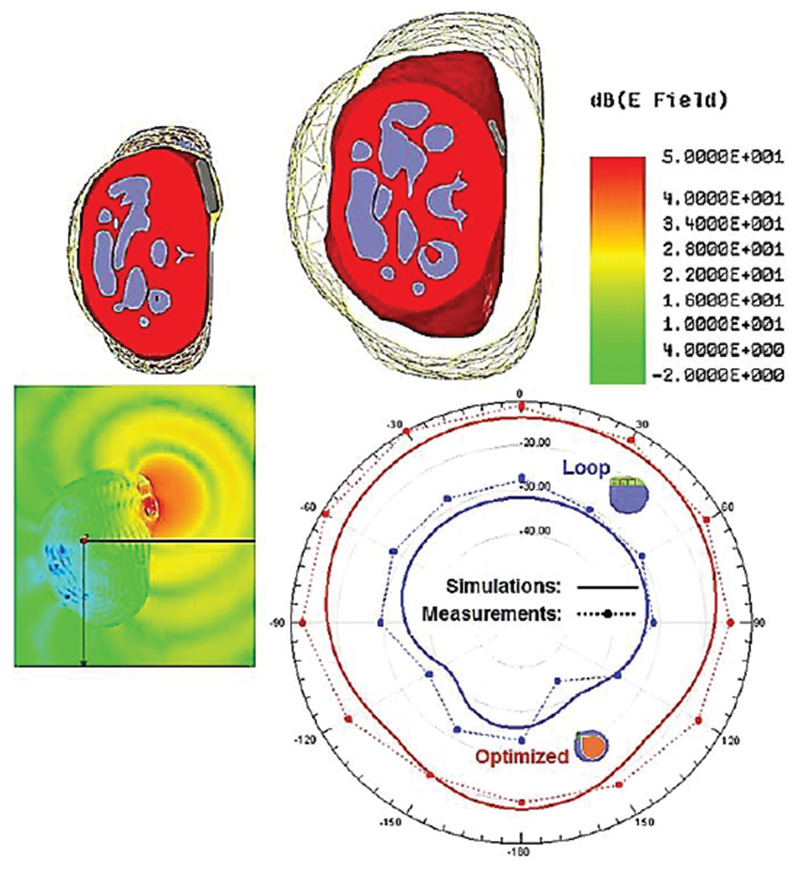
Near-body antenna performance for different body sizes [272].
In this paper, we do not specifically address safety issues of stand-alone BANs, which seem to be a relatively minor point of concern. MRI safety and MRI-conditional safety of implanted devices (including BAN) are discussed next.
F. MRI Safety
Regulatory and standardization organizations (e.g. FDA or IEC) require the determination of the specific absorption rate or SAR for MRI radiofrequency (RF) coil safety assessment. Different international safety standards have been developed to ensure that RF heating in MRI stays within safe limits. The major applicable standard is issued by the International Electrotechnical Commission (IEC) [273]. The IEC limits are now also accepted by the U.S. Food and Drug Administration. The IEC standard normal mode (mode of operation that causes no physiological stress to patients) limits global-body SAR to 2 W/kg, global-head SAR to 3.2 W/kg, local head and torso SAR to 10 W/kg, and local extremity SAR to 20 W/kg [189]. The global SAR limits are intended to ensure a body core temperature of 39°C or less [189],[273].
However, SAR measurements are not easily performed for human subjects in-vivo and, thus, SAR is typically derived from numerical electromagnetic simulations with virtual humans. A number of relevant references have already been provided in Table VI.
As an example, Fig. 24 [81] investigates how cerebrospinal fluid simulated as a single electrically connected object, and variation of the geometry of an anatomical human head model, influence the transmit and safety excitation efficiencies of a 7 T magnetic resonance imaging transmit array. There, an early ANSYS human body model without cerebrospinal fluid (CSF) is compared to the VHP-Female CAD model with a manifold CSF shell. The comparison results of Ref. [81] partially replicated in Fig. 24 indicate that the CSF shell simulated as a single electrically connected object partially shields the brain from the RF radiation and resulted in decreases of both transmit and safety excitation efficiencies on the order of 10-15%.
Fig. 24.
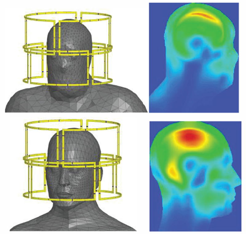
SAR10g as result of MRI exposure using VHP-Female v.3.0 mode 1 (top) with a continuous CSF shell versus a model with no CSF (bottom) [81].
G. MRI-Conditional Safety of Passive Implants
Multiphysics modeling of heating large passive metallic implants in an MRI coil is a problem of significant importance today [274],[275]. Numerical simulations with realistic human models are widely employed. As an example, Fig. 25 [274] shows the local SAR distribution (top) and the temperature rise (bottom) for a shoulder implant computed with COMSOL® Multiphysics for a realistic CAD NURBS human model derived from Visible Korean Human [36] via ScanIP software (Simpleware, Exeter UK).
Fig. 25.
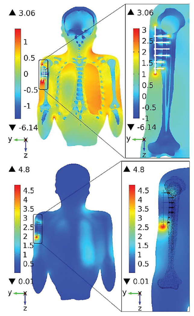
MRI-induced heating of a passive shoulder implant [274]. Top – SAR (log10); bottom - temperature rise after 900 s RF Application (C), slice parallel to humerus.
H. MRI-Conditional Safety of Active Implants
Patients with Active Implantable Medical Devices (AIMD) including BAN are generally denied access to MRI, despite that imaging modality’s preferred status for soft tissue imaging. However, it has been estimated that 17% of pacemaker patients need an MRI during the first 12 months of implantation [276]. During MRI, the RF fields will induce voltages at the various conductors external to the device enclosure. These voltages can cause device malfunction, or can be rectified by active elements within the AIMD and cause unintended stimulation of tissue. AIMD manufacturers evaluate conditional safety of devices in MRI by conservatively calculating these voltages using computational human models [276], [277].
The size of these devices compared to the wavelength provides some contrast to the corresponding analysis for passive implants. Recent example references in this area include [276]–[281].
IX. Major Low Frequency Applications
A. Neurostimulation
Transcranial Magnetic Stimulation (TMS).
Transcranial magnetic stimulation (TMS) with an external excitation coil is increasingly used as a diagnostic and therapeutic tool for neuropsychiatric disorders. Recent studies confirm the efficacy of Transcranial Magnetic Stimulation (TMS) as a non-invasive treatment of medication-resistant depression [282],[283] and in the US, at least four different devices, the Neuronetics Neurostar Stimulator, Brainsway H-Coil system, Magstim Magnetic Stimulator, and MagVenture Stimulator have been cleared by the Food and Drug Administration (FDA) for the treatment of medication-resistant depression [284],[285]. TMS has been proposed as a method to treat maternal depression while avoiding fetal exposure to drugs [286],[287] and the risk-benefit profile is argued to be better for TMS than for medications. Numerical modeling with virtual humans has been proven to be a very useful tool for TMS research. Early [288],[289] and recent [290]–[298] simulation results reveal both efficiency and safety of the TMS. As an example, Fig. 26 shows induced current distribution in a body of a pregnant patient (second trimester) due to CW (continuous wave) excitation with a figure-eight TMS coil used for safety estimates [93].
Fig. 26.
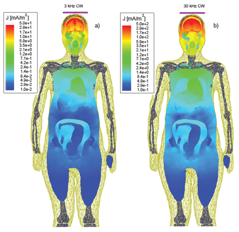
Induced current density distribution in a body of a pregnant patient due to CW excitation with a figure-eight TMS coil at two different test frequencies [93]
Transcranial Direct Current Stimulation (tDCS).
This neurostimulation method uses direct current delivered to the brain area of interest via electrodes on the scalp [299]–[301]. Dr. M. Bikson’s research group from the City University of New York is very active in this area including detailed simulations with human models and moving toward cellular mechanisms of tDCS (cf. [302]–[307]).
To illustrate differences and similarities between TMS and tDCS, Fig. 27 presents comparative simulations results for both methods using the same high-fidelity FEM head model [296] shown in Fig. 27a. Fig. 27b yields the TMS simulation results (the current in the coil is varied sinusoidally with a frequency of 5 kHz and a maximum rate of change of 67 A/μs) while Fig. 27c is the tDCS with total 1 mA injection current.
Fig. 27.
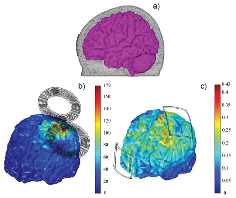
Magnitude of the E-field in the cortex (a) during TMS (b) and tDCS (c) [296]. The electric field scale is in V/m.
Evaluation of different numerical methods and their accuracy for a current injection problem (isotropic and anisotropic head models) has been performed in Ref. [308].
B. MEG/EEG Source Localization
EEG (Electroencephalography) and MEG (Magnetoencephalography) [309] source analyses have largely relied in the past upon (multi-layered) spherical conductor models of the head to simplify forward calculations of the brain’s magnetic field [310],[311]. However, it has been shown that the spherical models can contribute in the order of 1 cm to the localization bias in regions of the head that depart significantly from a sphere (inferior frontal and temporal). Given these limitations, realistic FEM/FDTD/BEM head models have been employed recently [180],[308],[311].
C. Tumor Treating Fields
One new development is represented by Tumor Treating Fields (TTFields), low-intensity electric fields in the frequency range of 100–500 kHz, which exhibit antimitotic activity in cancer cells. TTFields were approved by the U. S. Food and Drug Administration for the treatment of recurrent glioblastoma in 2011. Studies have shown that inhibition of cell division in glioma is achieved when the applied alternating electric field has a frequency in the range of 100–500 kHz and an amplitude of 1–3 V/cm [312]–[316]. Preclinical evidence and pilot studies suggest that TTFields could be also effective for treating certain types of lung cancer, and that treatment efficacy depends on the electric field intensity [317].
Extensive numerical simulations of the TTFields have recently been performed with detailed human models [197],[198],[317]–[319]. A unique feature of the most recent simulations pertinent to the human head is the full-scale anisotropic modeling [67],[198]. As an example, Fig. 28 [67] demonstrates electric field strength (V/cm) distribution in axial (top row), sagittal (middle row) and coronal (bottom row) slices through an artificial spherical tumor for the left panel electrode stimulations. Isotropic results are plotted on the left and corresponding anisotropic results for vN (volume normalized conductivity mapping [320]) and dM (direct conductivity mapping [149]) are illustrated in the middle and right columns respectively. The color range is the same for all figures and varies between 0 (dark blue) and 4 (dark red) V/cm.
Fig. 28.
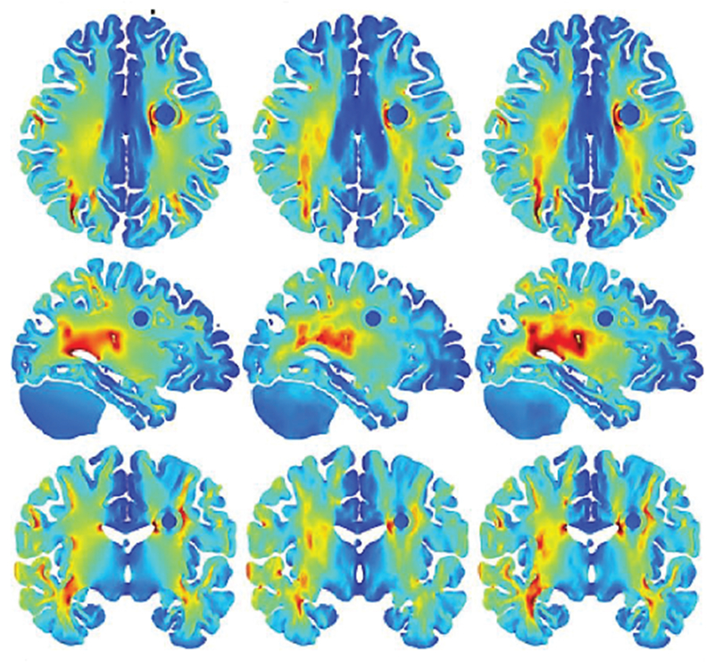
Electric field strength (V/cm) distribution in axial (top row), sagittal (middle row) and coronal (bottom row) slices through am artificial spherical tumor [67]. Anisotropic results for vN and dM are illustrated in the middle and right columns, respectively.
Ready-to-use open-access simulation packages [321] already exist for the low-frequency modeling tasks with human models.
X. Concluding Remarks
Anatomical human models (i.e. virtual humans) replicate local tissue responses of real humans and are being used today with exponentially increasing frequency for the safety assessment of various industrial and medical devices, and for diverse R&D purposes. Even today, detailed and accurate human models are difficult and very time-consuming to create. Two major challenges are related to the reconstruction of a unique subject-specific multi-tissue body structure with hundreds of individual parts and to a limited ability to justify the final model assembly and accuracy by direct measurements. Yet another challenge is related to the material properties, specifically to electrical permittivity and conductivity behavior at various frequencies and degrees of anisotropy.
The bulk of existing human models are assemblies of isotropic compartments that assume homogeneous volumes for every individual tissue. The modern tendency is to incorporate realistic anisotropic (fibrous) tissue structures into the computational models.
XI. Acknowledgements
Authors wish to thank Dr. M. Ackerman (formerly with the National Library of Medicine, NIH), Dr. Marc Horner (ANSYS, Inc.), Dr. H. Kimpara (Toyota Res. Labs), Drs. M. Iacono and L. Angelone (FDA), Dr. K. Sayrafian (NIST), Dr. A. Pascual-Leone (BIDMC, Harvard Med. School), Dr. N. Weiskopf, Dr. M. Kozlov and PD Dr. S. Geyer (Max Planck Inst., Germany), Dr. Z. Bomzon (Novocure Ltd.), Dr. P.C. Miranda (Univ. of Lisbon), Dr. C. Wenger (Novocure Ltd.), Dr. Ali Yulmaz (U. Texas Austin), Drs. L. Chen and G. Eaton (Bose Corp.), Drs. A. Venkatasubramanian and P. Fomitchov (Cambridge Consult.), A. Dr. K. Pahlavan (WPI), V.K. Rathi, S. Maliye, H.A. Win, A.L. Tran, X.J. Jackson, A.T. Htet, A.M. Helderman, N.S. Thang, T. Dolma, T.T. Trinh, M.W. Piazza, J. Zhang, E.H. Burnham, S Xie, R.M. Borwankar, D.S. Quinn, and P. D. Carberry for their input, inspiration, and useful comments.
This work has been partially supported by the NSF SBIR Phase I grant 1520168 and NIH/National Library of Medicine SBIR Phase I grant R43 LM012352-01A1 as well as NIH grants R00EB015445 and R01MH111829.
Contributor Information
Sergey N. Makarov, ECE Dept., Worcester Polytechnic Institute, Worcester, MA 01609; Athinoula A. Martinos Center for Biomedical Imaging, Massachusetts General Hospital, Harvard Medical School, Boston, MA 02114 (smakarov@mgh.harvard.edu)
Gregory M. Noetscher, ECE Dept., Worcester Polytechnic Institute, Worcester, MA 01609; Neva Electromagnetics, LLC., Yarmouth Port, MA 02675 (gregn@nevaem.com)
Janakinadh Yanamadala, ECE Dept., Worcester Polytechnic Institute, Worcester, MA 01609.
Matthew W. Piazza, ECE Dept., Worcester Polytechnic Institute, Worcester, MA 01609
Sara Louie, ANSYS, Inc., Cannonsburg, PA 15317 (sara.louie@ansys.com).
Alexander Prokop, CST AG, Darmstadt, Germany (alexander.prokop@cst.com).
Ara Nazarian, Beth Israel Deaconess Medical Center, Harvard Medical School, Boston, MA 02675 (anazaria@bidmc.harvard.edu).
Aapo Nummenmaa, Athinoula A. Martinos Center for Biomedical Imaging, Massachusetts General Hospital, Harvard Medical School, Boston, MA 02114 (nummenma@nmr.mgh.harvard.edu).
References
- [1].National Institute of Biomedical Imaging and Bioengineering, NIH: “Computational Modeling,” July 2013. Available: https://www.nibib.nih.gov/science-education/sciencetopics/computational-modeling
- [2].U.S. Food and Drug Administration, Center for Devices and Radiological Health “Reporting of Computational Modeling Studies in Medical Device Submissions: Draft Guidance for Industry and Food and Drug Administration Staff,” Jan 17th 2014. Available:http://www.fda.gov/downloads/MedicalDevices/DeviceRegulationandGuidance/GuidanceDocuments/UCM381813.pdf
- [3].Yang KH, Hu J, White NA, King AI, Chou CC, and Prasad P, “Development of numerical models for injury biomechanics research: a review of 50 years of publications in the Stapp Car Crash Conf.” Stapp Car Crash J, vol. 50, pp. 429–490, Nov. 2006, [DOI] [PubMed] [Google Scholar]
- [4].Iwamoto M, Kisanuki Y, Watanabe I, Furusu K, and Miki K, “Development of a finite element model of the total human model for safety (THUMS) and application to injury reconstruction,” Int. Research Council on Biomechanics of Injury, Proc. of the Int. Research Council on the Biomechanics of Injury Conf., vol. 30, pp. 1–12, Munich, Germany, Sep. 2002. [Google Scholar]
- [5].Shigeta K, Kitagawa Y, and Yasuki T, “Development of next generation human FE model capable of organ injury prediction,” Enhanced Safety of Vehicle Conf., Stuttgart, Germany, pp. 15–18, June 2009. [Google Scholar]
- [6].Iwamoto M, Nakahira Y, and Kimpara H, “Development and validation of the total human model for safety (THUMS) toward further understanding of occupant injury mechanisms in precrash and during crash,” Traffic Injury Prevention, vol. 16, pp. 1–13, 2015. [DOI] [PubMed] [Google Scholar]
- [7].Iwamoto M and Nakahira Y, “Development and Validation of the Total HUman Model for Safety (THUMS) Version 5 Containing Multiple 1D Muscles for Estimating Occupant Motions with Muscle Activation During Side Impacts,” Stapp Car Crash J, vol. 59, pp. 53–90, 2015. [DOI] [PubMed] [Google Scholar]
- [8].Total Human Model for Safety – THUMS. Available: http://www.lstc.com/thums, http://ls-dyna.jsol.co.jp/en/thums, https://www.dynamore.de/en/products/models/human.
- [9].Gayzik FS, Moreno DP, Geer CP, Wuertzer SD, Martin RS, and Stitzel JD, “Development of a full body CAD dataset for computational modeling: a multi-modality approach,” Ann Biomed Eng, vol. 39, pp. 2568–2583, 2011. [DOI] [PubMed] [Google Scholar]
- [10].Schwartz D, “Development of a Computationally Efficient Full Human Body Finite Element Model,” MS Thesis. Virginia Tech, Winston-Salem, NC. May 2015. Available: https://wakespace.lib.wfu.edu/bitstream/handle/10339/57119/Schwartz_wfu_0248M_10697.pdf [DOI] [PubMed] [Google Scholar]
- [11].Schwartz D, Guleyupoglu B, Koya B, Stitzel JD, and Gayzik FS “Development of a Computationally Efficient Full Human Body Finite Element Model,” Traffic Injury Prevention, vol. 16, suppl. 1, pp. S49–S56, 2015. [DOI] [PubMed] [Google Scholar]
- [12].Combest J and Wang J-T, “Status of the Global Human Body Models Consortium (GHBMC),” SAE Government & Industry Meeting, Washington, DC, Jan. 2016. Available: http://www.ghbmc.com/GHBMCStatus.pdf [Google Scholar]
- [13].Schneider LW, Robbins DH, Pflug MA, Snyder RG, “Anthropometry of motor vehicle occupants,” Report HS-806 717/UMTRI-83-53-2, University of Michigan Transportation Research Institute, 1983. [Google Scholar]
- [14].Okamoto Y, Murakami H, Demura S, Kato S, Yoshioka K, Sakamoto J, Kawahara N, and Tsuchiya H, “The effect of kyphotic deformity because of vertebral fracture: a finite element analysis of a 10 and 20 wedge-shaped vertebral fracture model,” The Spine Journal, vol. 15, no 4, pp. 713–720, 2015. [DOI] [PubMed] [Google Scholar]
- [15].Danelson KA and Stitzel JD, “Finite element model prediction of pulmonary contusion in vehicle-to-vehicle simulations of real-world crashes,” Traffic Injury Prevention, vol. 16, no. 6, pp. 627–636, 2015. [DOI] [PubMed] [Google Scholar]
- [16].Elemance: The Sole Distributor of the Global Human Body Models Consortium Family of Virtual Models of the Human Body. Online: http://www.elemance.com/, http://www.elemance.com/virtual-humanbody-models/
- [17].DeWerd LA and Kissick M, eds., The Phantoms of Medical and Health Physics, Springer, New York, 2014. [Google Scholar]
- [18].Xu G and Eckerman KF, Eds. Handbook of Anatomical Models for Radiation Dosimetry, CRS Press, Boca Raton. FL, 2009. [Google Scholar]
- [19].Computational human phantom, Wikipedia. Available: https://en.wikipedia.org/wiki/Computational_human_phantom
- [20].Xu G, “An exponential growth of computational phantom research in radiation protection, imaging, and radiotherapy: A review of the fifty-year history,” Phys. Med Biol, vol. 59, no. 18, pp. R233–R302, Sep. 2014. [DOI] [PMC free article] [PubMed] [Google Scholar]
- [21].IEEE Int. Committee on Electromagnetic Safety: Technical Committee 34: List of human phantoms. Available: http://grouper.ieee.org/groups/scc34/sc2/wg2/available%20human%20models.doc
- [22].Ackerman MJ, “The Visible Human Project®: From Body to Bits,” IEEE Pulse Magazine, July 2017, to appear. [DOI] [PubMed] [Google Scholar]
- [23].National Library of Medicine (U.S). Planning Panel on Electronic Imaging, “Electronic imaging: Report of the Board of Regents”, U.S. Department of Health and Human Services, Public Health Service, National Institutes of Health, 1990, NIH Publication Issue 90, Part 2197. [Google Scholar]
- [24].Spitzer V, Ackerman MJ, Scherzinger AL, and Whitlock DW, “The visible human male: A technical report,” J. Amer. Medical Informatics Assoc, vol. 3, no. 2, pp.118–130, 1996. [DOI] [PMC free article] [PubMed] [Google Scholar]
- [25].Ackerman MJ, “The Visible Human Project,” Proc. IEEE, vol. 86, no. 3, pp. 504–511, Mar. 1998. Available: https://www.nlm.nih.gov/research/visible/visible_human.html [Google Scholar]
- [26].Ackerman MJ, “The Visible Human Project®: From Body to Bits,” 38th Annual Int. Conf. of the IEEE Engineering in Medicine and Biology Society, Orlando, FL, Aug. 16-21, 2016. [DOI] [PubMed] [Google Scholar]
- [27].Christ A, Kainz W, Hahn EG, Honegger K, Zefferer M, Neufeld E, Rascher W, Janka R, Bautz W, Chen J, Kiefer B, Schmitt P, Hollenbach HP, Shen J, Oberle M, Szczerba D, Kam A, Guang JW, and Kuster N, “The Virtual Family - development of surface-based anatomical models of two adults and two children for dosimetric simulations,” Phys. Med. Biol, vol. 55, pp. 23–38, 2010. [DOI] [PubMed] [Google Scholar]
- [28].Gosselin M-C, Neufeld E, Moser H, Huber E, Farcito S, Gerber L, Jedensjo M, Hilber I, Gennaro F-D, and Llyod B, “Development of a New Generation of High-Resolution Anatomical Models for Medical Device Evaluation: The Virtual Population 3.0,” Phys. Med. and Biol, vol. 59, pp. 5287–5303, 2014. [DOI] [PubMed] [Google Scholar]
- [29].The Virtual Population. High-Resolution Anatomical Models for Computational Life Sciences. SPEAG AG, Flyer, EuCAP 2016, Davos, Switzerland, April 10-15 2016, 2 p. [Google Scholar]
- [30].Wu T, Tan L, Shao Q, Zhao C, Li Y, Conil E, Hadjem A, Wiart J, Lu B, Xiao L, Wang N, Xie Y, and Yang S, “Chinese adult anatomical models and the application in evaluation of RF exposures,” Phys. Med. Biol, vol. 56, no. 7, pp. 2075–89, 2011. [DOI] [PubMed] [Google Scholar]
- [31].Li A, Liu Q, Zeng S, Tang L, Zhong S, and Luo Q, “Construction and visualization of high-resolution 3D anatomical structure datasets for Chinese digital human,” Chinese Science Bulletin, vol. 53, pp. 1848–1854, 2008. [Google Scholar]
- [32].Yu D, Wang M, and Liu Q, “Development of Chinese reference man deformable surface phantom and its application to the influence of physique on electromagnetic dosimetry,” Phys. Med. Biol, vol. 60, no. 17, pp. 6833–6846, 2015. [DOI] [PubMed] [Google Scholar]
- [33].Zhang SX, Heng PA, Liu ZJ, Tan LW, Qiu MG, Li QY, Liao RX, Cui GY, Guo YL, Yang XP, Liu GJ, Shan JL, Liu JJ, Zhang WG, Chen XH, Chen JH, Wang J, Chen W, Lu M, You J, Pang XL, Xiao H, Xie YM, and Cheng JCY, “The Chinese visible human (CVH) datasets incorporate technical and imaging advances on earlier digital humans,” J. Anatomy, vol. 204 (Pt 3), pp. 165–73, 2004. [DOI] [PMC free article] [PubMed] [Google Scholar]
- [34].Zhang SX, Heng PA, and Liu ZJ, “Chinese visible human project,” Clinical Anatomy, vol. 19, no. 3, pp. 204–15, Apr. 2006. [DOI] [PubMed] [Google Scholar]
- [35].Nagaoka T, Watanabe S, Sakurai K, Kunieda E, Taki M, and Yamanaka Y “Development of realistic high-resolution whole-body voxel models of Japanese adult male and female of average height and weight, and application of models to radio-frequency electromagnetic-field dosimetry,” Phys. Med. Biol, vol. 49, no. 1, pp. 1–15, 2004. [DOI] [PubMed] [Google Scholar]
- [36].Lee AK, Choi WY, Chung MS, Choi HD, and Choi JI, “Development of Korean male body model for computational dosimetry,” ETRI Journal., vol. 28, pp.107–10, 2006. [Google Scholar]
- [37].Kim CH, Choi SH, Jeong JH, Lee C, and Chung MS, “HDRK-Man: a whole-body voxel model based on high-resolution color slice images of a Korean adult male cadaver,” Phys. Med. Biol, vol. 53, pp. 4093–4106, 2008. [DOI] [PubMed] [Google Scholar]
- [38].Lee AK, Byun JK, Park JS, Choi HD, and Yun J, “Development of 7-Year-Old Korean Child Model for Computational Dosimetry,” ETRI Journal, vol. 31, no. 2, pp. 237–239, 2009. [Google Scholar]
- [39].Yeom YS, Jeong JH, Kim CH, Han MC, Ham BK, Cho KW and Hwang SB, “HDRK-Woman: Whole-body Voxel Model Based on High-resolution Color Slice Images of Korean Adult Female Cadaver,” Phys. Med. Biol, vol. 59, no. 14, pp. 3969–3984, 2014. [DOI] [PubMed] [Google Scholar]
- [40].Dimbylow PJ, “Development of the female voxel phantom, NAOMI, and its application to calculations of induced current densities and electric fields from applied low frequency magnetic and electric fields,” Phys. Med. Biol, vol. 50, pp. 1047–1070, 2005. [DOI] [PubMed] [Google Scholar]
- [41].REMCOM. High-fidelity human meshes. NMR Group at Hershey Medical Center, PennState, Available: http://www.remcom.com/xf7-biological-meshes/ [Google Scholar]
- [42].CST Studio Suite 2013. European User Conf.. Online: https://www.cst.com/content/events/downloads/euc2013/5-4-2_cst_euc.pdf [Google Scholar]
- [43].Gao J, Munteanu I, Muller WFO, and Weiland T, “Generation of postured voxel-based human models for the study of step voltage excited by lightning current,” Advances in Radio Sci, vol. 9, pp. 99–105, 2011. [Google Scholar]
- [44].Massey J, Geyik C, Techachainiran N, and Yilmaz AE “AustinMan and AustinWoman: High Fidelity, Reproducible, and Open-Source Electromagnetic Voxel Models,” Bioelectromagnetics Society 34th Annual Meeting, Brisbane, Australia, June 2012. [Google Scholar]
- [45].Univ. Texas at Austin. Online: http://web2.corral.tacc.utexas.edu/AustinManEMVoxels/
- [46].Segars WP, Sturgeon G, Mendonca S, Grimes J, and Tsui BMW,, “4D XCAT phantom for multimodality imaging research,” Med. Phys,vol. 37, no. 9, pp. 4902–4915, 2010. [DOI] [PMC free article] [PubMed] [Google Scholar]
- [47].Segars WP, Bond J, Frush J, Hon S, Eckersley C, Williams CH, Feng J, Tward DJ, Ratnanather JT, Miller MI, Frush D, and Samei E, “Population of anatomically variable 4D XCAT adult phantoms for imaging research and optimization,” Med. Phys, vol. 40, no. 4, 2013. [DOI] [PMC free article] [PubMed] [Google Scholar]
- [48].Segars WP, Norris H, Sturgeon GM, Zhang Y, Bond J, Minhas A, Tward DJ, Ratnanather JT, Miller MI, Frush D, and Samei E, “The development of a population of 4D pediatric XCAT phantoms for imaging research and optimization,” Med. Phys, vol. 42, no. 8, pp. 4179–26, 2015. [DOI] [PMC free article] [PubMed] [Google Scholar]
- [49].Könik A, Connolly CM, Johnson KL, Dasari P, Segars WP, Pretorius PH, Lindsay C, Dey J, and King MA, “Digital anthropomorphic phantoms of non-rigid human respiratory and voluntary body motion for investigating motion correction in emission imaging,” Phys. Med. Biol vol. 59, no. 14, pp. 3669–3682, July 2014. [DOI] [PMC free article] [PubMed] [Google Scholar]
- [50].Segars WP, “Development of the XCAT Series of Computational Phantoms,” 38th Annual Int. Conf. of the IEEE Engineering in Medicine and Biology Society (EMBC 2016), Orlando, FL, Aug. 16-20 2016. [Google Scholar]
- [51].Erickson DW, Wells JR, Sturgeon GM, Samei E, Dobbins JT, Segars WP, and Lo JY, “Population of 224 realistic human subject-based computational breast phantoms”, Med. Phys, vol. 43, no. 1, Jan. 2016. [DOI] [PMC free article] [PubMed] [Google Scholar]
- [52].XCAT Phantoms. Online: https://olv.duke.edu/xcat
- [53].Yanamadala J, Rathi VK, Maliye S, Win HA, Tran AL, Kozlov MK, Noetscher GM, Nazarian A, and Makarov SN, “Segmentation of the Visible Human Project® (VHP) Female Cryosection Images within MATLAB® Environment,” 23rd Int. Meshing Roundtable (IMR23), London, England, Oct. 12-15, 2014. Available: http://www.imr.sandia.gov/papers/imr23.html [Google Scholar]
- [54].Yanamadala J, Noetscher GM, Rathi VK, Maliye S, Win HA, Tran AL, Jackson XJ, Htet AT, Kozlov M, Nazarian A, Louie S, and Makarov SN, “New VHP-Female V.2.0 Full-Body Computational Phantom and Its Performance Metrics Using FEM Simulator ANSYS HFSS,” 37th Annual Int. Conf. of the IEEE Engineering in Medicine and Biology Society (EMBC 2015), Milano, Italy, Aug. 25-29, 2015, pp. 3237–3241. [DOI] [PubMed] [Google Scholar]
- [55].Noetscher GM, Yanamadala J, Kozlov M, Louie S, Nazarian A, and Makarov S, “VHP-Female v3.0 FEM/BEM Computational Human Phantom,” 24th Int. Meshing Roundtable (IMR24), Austin, TX, Oct. 12-14, 2015. [Google Scholar]
- [56].Yanamadala J, Noetscher GM, Louie S, Prokop A, Kozlov M, Nazarian A, and Makarov SN, “Multi-Purpose VHP-Female Version 3.0 Cross-Platform Computational Human Model,” 10th European Conf. on Antennas and Propagation (EuCAP16), Davos, Switzerland, April 2016, pp. 1–5. [Google Scholar]
- [57].Tankaria H, Jackson XJ, Borwankar R, Srichandhru GNK, Tran AL, Yanamadala J, Noetscher GM, Nazarian A, Louie S, and Makarov SN, “VHP-Female Full-Body Human CAD Model for Cross-Platform FEM Simulations – Recent Development and Validations,” 38th Annual Int. Conf. of the IEEE Engineering in Medicine and Biology Society (EMBC 2016), Orlando, FL, Aug. 16-20, 2016. [DOI] [PubMed] [Google Scholar]
- [58].Noetscher GM, Yanamadala J, Louie S, Nazarian A, and Makarov SN, “Computational Human Model VHP-Female Derived from Datasets of the National Library of Medicine,” IEEE Pulse, April 27th 2016. Available: http://pulse.embs.org/march-2016/creating-acomputational-human-model/ [DOI] [PubMed] [Google Scholar]
- [59].Noetscher GM, Htet AT, Maino N, and Lacroix P, “The Visible Human Project Male CAD Based Computational Phantom and Its Use in Bioelectromagnetic Simulations,” 39th Annual Int. Conf. of the IEEE Engineering in Medicine and Biology Society (EMBC 2017), Jeju Island, Korea, July 11–15, 2017. [DOI] [PubMed] [Google Scholar]
- [60].Zhao L, Ye Q, Wu KL, Chen G, and Yu W, “A New High-Resolution Electromagnetic Human Head Model: A useful resource for a new specific-absorption-rate assessment model,” IEEE Antennas & Propagation Mag, vol. 58, no. 5, pp. 32–42, Oct 2016. [Google Scholar]
- [61].Iacono MI, Neufeld E, Akinnagbe E, Bower K, Wolf J, Oikanomidis IV, Sharma D, Lloyd B, Wilm BJ, Wyss M, Pruessmann KP, Jakab A, Makaris N, Cohen ED, Kuster N, Kainz W, and Angelone LM, “MIDA: A Multimodal Imaging-Based Detailed Anatomical Model of the Human Head and Neck,” PLoS One, vol. 10, no. 4, pp. 1–35, April 2015. [DOI] [PMC free article] [PubMed] [Google Scholar]
- [62].Neira LM, Mays RO, and Hagness SC, “Development and Application of Human Breast Phantoms in Microwave Diagnostic and Therapeutic Technologies,” 38th Annual Int. Conf. of the IEEE Engineering in Medicine and Biology Society, pp. 6018–6021, Orlando, FL, Aug. 16-21, 2016. [DOI] [PubMed] [Google Scholar]
- [63].Burfeindt MJ, Colgan TJ, Mays RO, Shea JD, Behdad N, Veen BDV, and Hagness SC, “MRI-Derived 3-D-Printed Breast Phantom for Microwave Breast Imaging Validation,” IEEE Anennas Wireless Propag. Lett, vol. 11, pp. 1610–1613, Jan. 2012. [DOI] [PMC free article] [PubMed] [Google Scholar]
- [64].Zastrow E, Davis SK, Lazebnik M, Kelcz F, Veen BDV, and Hagness SC, “Development of anatomically realistic numerical breast phantoms with accurate dielectric properties for modeling microwave interactions with the human breast,” IEEE Trans. Biomed. Eng, vol. 55, no. 12, pp. 2792–2800, Dec. 2008. [DOI] [PMC free article] [PubMed] [Google Scholar]
- [65].The UWCEM Numerical Breast Phantom Repository Phantom Repository. Online: http://uwcem.ece.wisc.edu/phantomRepository.html.
- [66].Miranda PC, Salvador R, Wenger C, and Fernandes SR, “Computational Models of Non-Invasive Brain and Spinal Cord Stimulation,” 38th Annual Int. Conf. of the IEEE Engineering in Medicine and Biology Society (EMBC 2016), pp. 6457–6460, Orlando, FL, USA, 2016. [DOI] [PubMed] [Google Scholar]
- [67].Wenger C, Salvador R, Basser PJ, and Miranda PC, “The electric field distribution in the brain during TTFields therapy and its dependence on tissue dielectric properties and anatomy: a computational study,” Phys. Med. Biol, vol. 60, pp. 7339–57, 2015. [DOI] [PMC free article] [PubMed] [Google Scholar]
- [68].Zhang Y, Kim S, Erdman AG, Roberts KP, and Timm GW, “Feasibility of using a computer modeling approach to study SUI induced by landing a jump,” Ann. of Biomedical Eng, vol. 37, no. 7, pp. 1425–1433, 2009. [DOI] [PubMed] [Google Scholar]
- [69].Zhang Y, Sweet RM, Metzger GJ, Burke D, Erdman AG, and Timm GW, “Advanced finite element mesh model of female SUI research during physical and daily activities,” Stud. Health Tech. Informatics, vol. 142, pp. 447–452, 2009. [PubMed] [Google Scholar]
- [70].Mitsuhashi NK, Fujieda K, Tamura T, Kawamoto S, Takagi T, and Okubo K, “BodyParts3D: 3D Structure Database for Anatomical Concepts,” Nucleic Acids Research, vol. 37 pp. 782–785, 2009. Available: http://lifesciencedb.jp/bp3d/; see also https://dbarchive.biosciencedbc.jp/en/bodyparts3d/desc.html [DOI] [PMC free article] [PubMed] [Google Scholar]
- [71].Setsompop K, Kimmlingen R, Eberlein E, Witzel T, Adad JC, McNab JA, Keil B, Tisdall MD, Hoecht P, Dietz P, Cauley SF, Tountcheva V, Matschl V, Lenz VH, Heberlein K, Potthast A, Thein H, Horn JV, Toga A, Schmitt F, Lehne D, Rosen BR, Wedeen V, Wald LL, “Pushing the limits of in vivo diffusion MRI for the Human Connectome Project,” Neuroimage, vol. 80, pp. 220–233, Oct. 2013. [DOI] [PMC free article] [PubMed] [Google Scholar]
- [72].Keil B, Blau JN, Biber S, Hoecht P, Tountcheva V, Setsompop K, Triantafyllou C, and Wald LL, “A 64-channel 3T array coil for accelerated brain MRI,” Magnetic Resonance in Medicine, vol. 70, no. 1, pp. 248–258, July 2013. [DOI] [PMC free article] [PubMed] [Google Scholar]
- [73].Fan Q, Nummenmaa A, Witzel T, Zanzonico R, Keil B, Causley S, Polimeni JR, Tisdall D, Dijk KRV, Buckner RL, Wedeen VJ, Rosen BR, and Wald LL, “Investigating the capability to resolve complex white matter structures with high b-value diffusion magnetic resonance imaging on the MGH-USC Connectom scanner,” Brain Connectivity, vol. 4, no. 9, pp. 718–726, Nov.2014. [DOI] [PMC free article] [PubMed] [Google Scholar]
- [74].Fischl B, “FreeSurfer,” Neuroimage, vol. 62(2), pp. 774–781, Aug. 2012. [DOI] [PMC free article] [PubMed] [Google Scholar]
- [75].MGH-UCLA Consortium. Human Connectome Project Online. Available: http://www.humanconnectomeproject.org/
- [76].Han X, Phan DL, Tosun D, Rettmann ME, Lucas B, Roy S, Xu C, and Prince JL, “CRUISE: Cortical Reconstruction Using Implicit Surface Evolution.” NeuroImage, vol. 23, no. 3, pp. 997–1012, 2004. [DOI] [PubMed] [Google Scholar]
- [77].Bazin P-L, Ellingsen LM, and Pham DL, “Digital Homeomorphisms in Deformable Registration,” Int. Conf. on Information Processing in Medical Imaging, Kerkrade, 2007. [DOI] [PubMed] [Google Scholar]
- [78].Landman BA, Bogovic JA, Carass A, Chen M, Roy S, Shiee N, Yang Z, Kishore B, Pham D, Bazin PL, Resnick SM, and Prince JL, “System for Integrated Neuroimaging Analysis and Processing of Structure,” Neuroinformatics, vol. 11, no. 1, pp. 91–103, 2013. [DOI] [PMC free article] [PubMed] [Google Scholar]
- [79].Bogovic J, Prince JL, and Bazin PL, “A Multiple Object Geometric Deformable Model for Image Segmentation,” Computer Vision and Image Understanding, vol. 117, no. 2, pp. 145–57, 2013. [DOI] [PMC free article] [PubMed] [Google Scholar]
- [80].Bazin P-L, Weiss M, Dinse J, Schafer A, Trampel R, and Turner R, “A Computational Framework for Ultra-High Resolution Cortical Segmentation at 7 Tesla,” NeuroImage, vol. 93, no. 2, pp. 201–209, 2014. [DOI] [PubMed] [Google Scholar]
- [81].Kozlov M, Bazin P-L, Moller HE, and Weiskopf N, “Influence of Cerebrospinal Fluid on Specific Absorption Rate Generated by 300 MHz MRI Transmit Array,” 10th European Conf. on Antennas and Propagation, pp. 1–5, Davos, Switzerland, Apr. 10-15, 2016. [Google Scholar]
- [82].Wolfram Alpha Human Anatomy Tool., Online: https://www.wolframalpha.com/examples/HumanAnatomy.html
- [83].Nagaoka T, Niwa T, and Watanabe S, “SAR calculation in semihomogeneous human models of pregnancy for RF exposure,” in Asia-Pacific Int. Sym. on Electromagnetic Compatibility, pp. 444–447, Taipei, 2015. [Google Scholar]
- [84].Nagaoka T, Togashi T, Saito K, Takahashi M, Ito K, and Watanabe S, “An anatomically realistic whole-body pregnant-woman model and specific absorption rates for pregnant-woman exposure to electromagnetic plane waves from 10 MHz to 2 GHz,” Phys. Med. Biol, vol. 52, no. 22, pp. 6731–6745, Oct. 2007. [DOI] [PubMed] [Google Scholar]
- [85].Nagaoka T, Saito K, Takahashi M, Ito K, and Watanabe S, “Estimating specific absorption rates in pregnant women by using models at 12-, 20-, and 26-weeks’ gestation for plane wave exposures,” Int. Symp. On Electromagnetic Compatibility - EMC Europe, pp. 1–4, Hamburg, 2008. [Google Scholar]
- [86].Hand JW, Li Y, Thomas EL, Rutherford MA, and Hajnal JV, “Prediction of specific absorption rate in mother and fetus associated with MRI examinations during pregnancy,” Magn. Reson. Med, vol. 55, no. 4, pp. 883–893, Apr. 2006. [DOI] [PubMed] [Google Scholar]
- [87].Dimbylow P, “Development of pregnant female, hybrid voxelmathematical models and their application to the dosimetry of applied magnetic and electric fields at 50 Hz,” Phys. Med. Biol, vol. 51, no. 10, pp. 2383–2394, Apr. 2006. [DOI] [PubMed] [Google Scholar]
- [88].Cech R, Leitgeb N, and Pediaditis M, “Fetal exposure to low frequency electric and magnetic fields,” Phys. Med. Biol, vol. 52, no. 4, pp. 879–888, Jan. 2007. [DOI] [PubMed] [Google Scholar]
- [89].Becker J, Zankl M, Fill U, and Hoeschen C, “Katja - the 24th week of virtual pregnancy for dosimetric calculations,” Polish J. of Medical Physics and Eng, vol. 14, no. 1, pp. 13–19, Jan. 2008. [Google Scholar]
- [90].Shi CY and Xu XG, “Development of a 30-week-pregnant female tomographic model from computed tomography (CT) images for Monte Carlo organ dose calculations,” Med. Phys, vol. 31, no. 9, pp. 2491–2497, Sep. 2004. [DOI] [PubMed] [Google Scholar]
- [91].Xu XG, Talanenko V, Zhang J, and Shi C, “A boundary-representation method for designing whole-body radiation dosimetry models: pregnant females at the ends of three gestational periods--RPI-P3, -P6 and -P9,” Phys. Med. Biol, vol. 52, no. 23, pp. 7023–7044, Nov. 2007. [DOI] [PubMed] [Google Scholar]
- [92].Tankaria H, Jackson XJ, Borwankar R, Srichandhru GNK, Tran AL, Yanamadala J, Makarov SN, and Pascual-Leone A, “Full-Body FEM Pregnant Woman Model and Applications,” 38th Annual Int. Conf. of the IEEE Engineering in Medicine and Biology Society (EMBC 2016), Orlando, FL, Aug. 16-20 2016. [Google Scholar]
- [93].Yanamadala J, Noetscher GM, Makarov S, and Pascual-Leone A, “Estimates of Peak Electric Fields Induced by Transcranial Magnetic Stimulation in Pregnant Women As Patients Using an FEM Full-Body Model,” 39th Annual Int. Conf. of the IEEE Engineering in Medicine and Biology Society (EMBC 2017), Jeju Island, Korea, July 11-15, 2017. [DOI] [PubMed] [Google Scholar]
- [94].Zygote Media Group, Inc. ZygoteBody−. Online: https://zygotebody.com/about.
- [95].Genc KO, Segars P, Cockram S, Thompson D, Horner M, Cotton R, and Young P, “Workflow for creating a simulation ready virtual population for finite element modeling,” J. Med. Devices, vol. 7, no. 4, Dec. 2013. [Google Scholar]
- [96].Sezgin M and Sankur B, “Survey over image thresholding techniques and quantitative performance evaluation,” Journal of Electronic Imaging, vol. 13, no. 11, pp. 46–165, Jan. 2004. [Google Scholar]
- [97].Yushkevich PA, Piven J, Hazlett HC, Smith RG, Ho S, Gee JC, and Gerig G, “User-guided 3D active contour segmentation of anatomical structures: Significantly improved efficiency and reliability,” Neuroimage, vol. 31, no. 3, pp.1116–1128, Jul. 2006. [DOI] [PubMed] [Google Scholar]
- [98].Yushkevich PA, Gao Y, and Gerig G, “ITK-SNAP: An interactive tool for semi-automatic segmentation of multi-modality biomedical images,” 38th Annu. Int. Conf. of the IEEE Eng. in Medicine and Biology Soc., Orlando, FL, Aug. 16-21, 2016. [DOI] [PMC free article] [PubMed] [Google Scholar]
- [99].Pham DL, Xu C, and Prince JL, “Current Methods in Medical Image Segmentation,” Annu. Review of Biomedical Eng, vol. 2, pp. 315–337, Aug. 2000. Available: http://www.annualreviews.org/doi/full/10.1146/annurev.bioeng.2.1.315 [DOI] [PubMed] [Google Scholar]
- [100].Zhao F and Xie X, “An Overview of Interactive Medical Image Segmentation,” Ann. of the BMVA, vol. 2013, no. 7, pp 1–22, 2013. Available: http://www.bmva.org/annals/2013/2013-0007.pdf [Google Scholar]
- [101].Internet Analysis Tools Registry. Harvard Univ., Available: http://www.cma.mgh.harvard.edu/iatr/index.php [Google Scholar]
- [102].Athinoula A Martinos Center for Biomedical Imaging, Massachusetts General Hospital, Harvard Medical School FreeSurfer. Online: https://surfer.nmr.mgh.harvard.edu/
- [103].Oxford’s Brain Imaging Library FSL. Online: https://fsl.fmrib.ox.ac.uk/fsl/fslwiki/FSL
- [104].Slicer4: The free cross-platform open-source medical image processing and visualization system. Online: http://download.slicer.org/
- [105].USARIEM Models. Available: https://www.rt.com/usa/338688-usarmy-avatar-soldiers/; http://www.army-technology.com/news/newsusarmy-to-develop-3-d-full-anatomy-avatar-of-soldiers-4859541
- [106].Möller and Trumbore B, “Fast, Minimum Storage Ray/Triangle Intersection,” J. of Graph. Tools, vol. 2, pp. 21–28, 1997. [Google Scholar]
- [107].Lorensen WE and Cline HE “Marching cubes: A high resolution 3D surface construction algorithm,” Comput. Graph, vol. 21, no. 4, pp. 163–169, 1987. [Google Scholar]
- [108].Hilton A, Stoddart AJ, Illingworth J, and Windeatt T, “Marching Triangles: Range Image Fusion for Complex Object Modeling,” Proc. Of 3rd IEEE Int. Conf. Image Process., Lausanne, 1996, vol. 2, pp. 381–384. [Google Scholar]
- [109].Bernardini F, Mittleman J, Rushmeier H, Silva C and Taubin G, “The ball pivoting algorithm for surface reconstruction,” IEEE Trans. Vis. Comput. Graph, vol. 5, no. 4, pp. 349–359, Oct-Dec. 1999. [Google Scholar]
- [110].Bhaniramka P, Wenger R and Crawfis R, “Isosurface construction in any dimension using convex hulls,” IEEE Trans. on Vis. Comput. Graph, vol. 10, no. 2, pp. 130–141, Mar-Apr. 2004. [DOI] [PubMed] [Google Scholar]
- [111].Wenger R and Peters AK, Isosurfaces: Geometry, Topology, and Algorithms, CRC Press, Boca Raton, 2013. [Google Scholar]
- [112].Le Tran A and Makarov S, “Degree of RF MRI Coil Detuning for an Anatomically Realistic Respiratory Cycle Modeled with the Finite Element Method,” 39th Annual Int. Conf. of the IEEE Engineering in Medicine and Biology Society (EMBC 2017), Jeju Island, Korea, July 11–15, 2017. [DOI] [PubMed] [Google Scholar]
- [113].Gammon M, “CAD Clean-up for Meshing. What could possibly go wrong?” Short Course. 23rd Int. Meshing Roundtable, London, UK, pp. 1–70, Oct. 12-15, 2014. [Google Scholar]
- [114].MeshLab, Available: http://meshlab.sourceforge.net/
- [115].Moreland K, ParaView User’s Guide v.3.12., Kitware Inc., Sandia National Lab., CSimSoft, 2011.Available: http://www.itk.org/Wiki/ParaView/Users_Guide/Table_Of_Contents [Google Scholar]
- [116].Ortega FA, GMV 4.5 General Mesh Viewer User’s Guide. Los Alamos: National Laboratory, CPFD Software; 2011. Available: http://www.generalmeshviewer.com/. [Google Scholar]
- [117].Hemmer M, The CGAL Project. CGAL User and Reference Manual. CGAL Editorial Board, 2013. Available: http://doc.cgal.org/latest/Manual/how_to_cite_cgal.html [Google Scholar]
- [118].Garland M and Heckbert PS, “Surface simplification using quadric error metrics,” 24th Annu. Conf. on Comput. Graph. and Interactive Techniques. pp. 209–216. 1997. [Google Scholar]
- [119].Field D, “Laplacian smoothing and delaunay triangulations,” Commun. Appl. Numerical Methods, vol. 4, pp. 709–712, 1998. [Google Scholar]
- [120].Freitag LA, “On Combining Laplacian And Optimization-Based Mesh Smoothing Techniques,” Trends in Unstructured Mesh Generation, pp. 37–43, 1997. [Google Scholar]
- [121].Vollmer J, Mencl R, and Müller H, “Improved Laplacian smoothing of noisy surface meshes,” Comput. Graph. Forum, vol. 18, pp. 131–138, Sept. 1999. [Google Scholar]
- [122].Mukherje N, “A Hybrid, variational 3D smoother for orphaned shell meshes,” 11th Int. Meshing Roundtable (IMR11), Ithaca, New York, 2002. [Google Scholar]
- [123].Chen L, “Mesh smoothing schemes based on optimal Delaunay triangulations,” 13th Int. Meshing Roundtable (IMR13), Williamsburg, VA, pp. 109–120, 2004. [Google Scholar]
- [124].Garimella RV, Shashkov MJ, and Knupp PM, “Triangular and Quadrilateral Surface Mesh Quality Optimization Using Local Parametrization,” Comput. Methods in Appl. Mechanics and Eng, vol. 193, no. 9–11, pp. 913–928, Mar. 2004 [Google Scholar]
- [125].Erten H, Üngör A, and Zhao C, “Mesh Smoothing Algorithms for Complex Geometries,” 18th Int. Meshing Roundtable (IMR18), Salt Lake City, UT, 2009, pp. 175–193. [Google Scholar]
- [126].Lo SH, “Automatic mesh generation over intersecting surfaces, “Int. J. Numerical Methods Eng, vol. 38, pp. 943–954, 1995. [Google Scholar]
- [127].Lo SH and Wang WX, “A fast robust algorithm for the intersection of triangulated surfaces,” Engineering with Computers, vol. 20, pp.11–21, 2004. [Google Scholar]
- [128].Elsheikh AH, and Elsheikh M, “A reliable triangular mesh intersection algorithm and its application in geological modelling,” Engineering with Computers, vol. 30, pp. 143–157, 2014. [Google Scholar]
- [129].Coelho LCG, Gattass M, and de Figueiredo LH, “Intersecting and Trimming Parametric Meshes on Finite-Element Shells,” Int. J. for Numerical Methods in Eng, vol. 47, no. 4 , pp. 777–800, Feb. 2000. [Google Scholar]
- [130].Lira WM, Coelho LCG and Martha LF, “Multiple Intersections of Finite-Element Surface Meshes,” 11th Int. Meshing Roundtable, Ithaca, NY, 2002. [Google Scholar]
- [131].Lindenbeck CH, Ebertb HD, Ulmera H, Lavoranteb LP and Pfluga R, “TRICUT: a program to clip triangle meshes using the rapid and triangle libraries and the visualization toolkit,” Comput. & Geosciences, vol. 28, no. 7, pp. 841–850, 2002. [Google Scholar]
- [132].Hughes JF, van Dam A, McGuire M, Sklar DF, Foley JD, Feiner SK and Kurt Akeley, Computer Graphics: Principles and Practice, 3rd Ed., Addison-Wesley Professional, 2013. [Google Scholar]
- [133].Gabriel C, “Compilation of the dielectric properties of body tissues at RF and microwave frequencies,” Armstrong Laboratory, Brooks Air Force Base, Tech. Rep. AL/OE-TR-1996–0037, 1996. [Google Scholar]
- [134].Gabriel C, Gabriel S, and Corthout E, “The dielectric properties of biological tissues: I. Literature survey,” Phys. Med. Biol, vol. 41, pp. 2231–2249, Nov.1996. [DOI] [PubMed] [Google Scholar]
- [135].Gabriel S, Lau RW, and Gabriel C, “The dielectric properties of biological tissues: II. Measurements in the frequency range 10 Hz to 20 GHz,” Phys. Med. Biol, vol. 41, pp. 2251–2269, Nov.1996. [DOI] [PubMed] [Google Scholar]
- [136].Gabriel S, Lau RW, and Gabriel C, “The dielectric properties of biological tissues: III. Parametric models for the dielectric spectrum of tissues,” Phys. Med. Biol, vol. 41, pp. 2271–2293, Nov.1996. [DOI] [PubMed] [Google Scholar]
- [137].Gabriel C, Peyman A, and Grant EH, “Electrical conductivity of tissue at frequencies below 1 MHz,” Phys. Med. Biol, vol. 54, pp. 4863–78, Aug. 2009. [DOI] [PubMed] [Google Scholar]
- [138].Hasgall PA, Neufeld E, Gosselin MC, Klingenböck A, Kuster N, Klingenbock A, Hasgall P, and Gosselin M, “IT’IS Database for thermal and electromagnetic parameters of biological tissues,” Version 3.0, Sep. 1st, 2015. Available: www.itis.ethz.ch/database.
- [139].Wagner T, Eden U, Rushmore J, Russo CJ, Dipietro L, Frengi F, Simon S, Rotman S, Pitskel NB, Ramos-Estebanez C, Pascual-Leone A, Grodzinsky AJ, Zahn M, and Valero-Cabre A, “Impact of brain tissue filtering on neurostimulation fields: a modeling study,” Neuroimage, vol. 85, no. 3, pp.1048–57, 2014. [DOI] [PMC free article] [PubMed] [Google Scholar]
- [140].Sachse FB, Wolf M, Werner C, and Meyer-Waarden K, “Extension of anatomical models of the human body: Three-dimensional interpolation of muscle fiber orientation based on restrictions,” J. Comput. Inf. Techl, vol. 6, pp. 95–101, 1998. [Google Scholar]
- [141].Sachse FB, Werner CD, Meyer-Waarden K, and Dossel O, “Comparison of solutions to the forward problem in electrophysiology with homogeneous, heterogeneous and anisotropic impedance models,” Biomed. Tech, vol. 42, pp. 277–280, 1997. [Google Scholar]
- [142].Motrescu VC and Rienen UV, “Computation of electrostatic fields in anisotropic human tissues using the finite integration technique (FIT),” Adv.Radio Sci, vol. 2, pp. 309–313, 2004. [Google Scholar]
- [143].Motrescu VC and Rienen UV, “Simulation of Slowly Varying Electromagnetic Fields in the Human Body Considering the Anisotropy of Muscle Tissues,” IEEE Trans. Magn, vol. 42, no. 4, pp. 747–750, 2006. [Google Scholar]
- [144].Fischer SA, Three-Dimensional Anatomically Accurate Finite Element Model For Nerve Fiber Activation Simulation Coupling, MS thesis, California Polytechnic State University, 2015. [Google Scholar]
- [145].Neufeld E, Iacono MI, Akinnagbe E, Wolf J, Oikonomidis IV, Sharma1 D, Wilm B, Wyss M, Jakab A, Cohen E, Kuster N, Kainz W, and Angelone LM, “Computational platform combining detailed and precise functionalized anatomical phantoms with EM-Neuron interaction modeling,” General Assembly and Scientific Symposium (URSI GASS), 2014 XXXIth URSI, IEEE, Beijing, China, Aug 2014, pp. 1–4. [Google Scholar]
- [146].Neufeld E, Oikonomidis IV, Iacono MI, Akinnagbe E, Angelone LM, Kainz W, and Kuster N, “Simulation platform for coupled modeling of EM-induced neuronal dynamics and functionalized anatomical models,” 7th Annual Int. IEEE EMBS Conf. on Neural Engineering, Montpellier, France, 22 – 24 April, 2015. [Google Scholar]
- [147].Neufeld E, Oikonomidis IV, and Kuster N, “Thresholds for interference with neuronal activity,” 2015 Asia-Pacific Symposium on Electromagnetic Compatibility (APEMC) IEEE, Taipei, May 2015. [Google Scholar]
- [148].Bihan DL, Mangin JF, Poupon C, Clark CA, Pappata S, Molko N, and Chabriat H, “Diffusion tensor imaging: Concepts and applications,” J. of Magnetic Resonance Imaging, vol. 13, no. 4, pp. 534–46, 2001. [DOI] [PubMed] [Google Scholar]
- [149].Tuch DS, Wedeen VJ, Dale AM, George JS, and Belliveau JW, “Conductivity tensor mapping of the human brain using diffusion tensor MRI,” Proc. of the National Academy of Sciences of the United States of America, vol. 98 , no. 20, pp. 11697–701, 2001. [DOI] [PMC free article] [PubMed] [Google Scholar]
- [150].Tuch DS, Reese TG, Wiegell MR, and Wedeen VJ, “Diffusion MRI of complex neural architecture,” Neuron, vol. 40, no. 5, pp. 885–95, Dec. 2003. [DOI] [PubMed] [Google Scholar]
- [151].Wedeen VJ, “Diffusion spectrum magnetic resonance imaging (DSI) tractography of crossing fibers,” Neuroimage, vol. 41, no. 4, pp. 1267–77, 2008. [DOI] [PubMed] [Google Scholar]
- [152].Tuch DS, “Q-ball imaging,” Magnetic resonance in medicine, vol. 52, no. 6, pp. 1358–72, Dec. 2004. [DOI] [PubMed] [Google Scholar]
- [153].Makarov SN, Pascual-Leone A, and Nummenmaa A, “Modeling fiberlike conductivity structures via the boundary element method using thinwire approximation. I Construction of basis functions,” 38th Annual Int. Conf. of the IEEE Engineering in Medicine and Biology Society, pp. 6473–6476, Orlando, FL, Aug. 16–21, 2016. [DOI] [PubMed] [Google Scholar]
- [154].Makarov SN, Pascual-Leone A, and Nummenmaa A, “Computational modeling of complex fibrous tissue geometries,” IEEE Pulse Magazine, July/Aug. 2017, in press. [DOI] [PubMed] [Google Scholar]
- [155].Fan Q, Witzel T, Nummenmaa A, Van Dijk KRA, Van Horn JD, Drews MK, Somerville LH, Sheridan MA, Santillana RM, Snyder J, Hedden T, Shaw EE, Hollinshead MO, Renvall V, Zanzonico R, Keil B, Cauley S, Polimeni JR, Tisdall D, Buckner RL, Wedeen VJ, Wald LL, Toga AW and Rosen BR, “MGH-USC Human Connectome Project datasets with ultra-high b-value diffusion MRI,” NeuroImage, vol. 124, pp. 1108–1114, Jan. 2016. [DOI] [PMC free article] [PubMed] [Google Scholar]
- [156].Fan Q, Nummenmaa A, Polimeni JR, Witzel T, Huang SY, Wedeen VJ, Rosen BR and Wald LL, “High b-value and high Resolution Integrated Diffusion (HIBRID) imaging,” NeuroImage, vol. 150, pp. 162–176, April 15 2017. [DOI] [PMC free article] [PubMed] [Google Scholar]
- [157].Bondeson A, Rylander T, and Ingelström P, Computational Electromagnetics , Springer, New York, 2005, Series: Texts in Applied Mathematics, Vol. 51. [Google Scholar]
- [158].Yee KS, “Numerical solution of initial boundary value problem involving Maxwell’s equations in isotropic media,” IEEE Trans. Antennas Propag, vol. 14, 1966, pp. 302–307. [Google Scholar]
- [159].Taflove A, Computational Electrodynamics, The Finite Difference Time Domain Approach, Third Ed., Artech House, Norwood, MA, 2005. [Google Scholar]
- [160].Weiland T, “A discretization method for the solution of Maxwell’s equations for six-component fields,” Int. J. Electron. Commun. (AEÜ), vol. 31, no. 3, pp. 116–120, 1977. [Google Scholar]
- [161].Clemens M and Weiland T, “Discrete Electromagnetics with the finite integration technique,” Progress in Electromagnetics Research, PIER 32, pp. 65–87, 2001. [Google Scholar]
- [162].Thoma P and Weiland T, “A consistent subgridding scheme for the finite difference time domain method,” Int. J. Numerical Modelling, vol. 9, pp. 359–374, 1996. [Google Scholar]
- [163].Christopoulos C, The Transmission Line Modeling Method: TLM, Piscataway, NY, IEEE Press, 1995. ISBN 978–0-19–856533-8. [Google Scholar]
- [164]. Online: https://www.cst.com/Products/CSTmws/TLM-Solver.
- [165].Cendes ZJ, “Vector Finite Elements for Electromagnetic Field Computation,” IEEE Trans. Magn, vol. MAG-27, pp. 3953–3966, 1991. [Google Scholar]
- [166].Lee JF, Sun DK, Cendes ZJ, “Tangential vector finite elements for electromagnetic field computation,” IEEE Trans. Magn, vol. MAG-27, pp. 4032–4035, 1991. [Google Scholar]
- [167].Sun D, Manges J, Yuan X, Cendes Z, “Spurious modes in finiteelement methods,” IEEE Antennas Propagat. Mag, vol. 37, no. 5, pp. 12–24. 1995. [Google Scholar]
- [168].Nédélec C, “Mixed finite elements in R3,” Numerische Mathematik, 35:315–341, 1980. [Google Scholar]
- [169].Kozlov M and Turner R, “Comparison of Ansoft HFSS and CST Microwave Studio Simulation Software for Multi-channel Coil Design and SAR Estimation at 7T MRI,” PIERS ONLINE, vol. 6, no. 4, pp. 395–399, 2010. [Google Scholar]
- [170].Cockburn B, Karniadakis G, and W Shu C, Discontinuous Galerkin Methods: Theory, Computation and Applications, Lecture Notes in Computational Science and Engineering, Springer-Verlag, New York, vol. 11, 2000. [Google Scholar]
- [171].Hesthaven J and Warburton T, Nodal Discontinuous Galerkin Methods Algorithms, Analysis, and Applications, Springer series: Texts In Applied Mathematics, vol.54, 2007. [Google Scholar]
- [172].Buffa A, Perugia I, “Discontinuous Galerkin approximation of the Maxwell eigenproblem”,SIAM J. Numer. Anal, vol. 44, p. 2198–2226, 2006. [Google Scholar]
- [173].Dolean V, Fahs H, Fezoui L, and Lanteri S, “Locally implicit discontinuous Galerkin method for time domain electromagnetics,” Journal of Computational Physics, vol. 229, no. 2, Jan. 2010. [Google Scholar]
- [174].Harrington RF, Field Computation by Moment Methods, Macmillan, New York, 1968. [Google Scholar]
- [175].Harrington RF, “Origin and development of the method of moments for field computation,” IEEE Antennas Propagat. Mag, vol. 32, no. 3, pp. 31–35, June 1990. [Google Scholar]
- [176].Vorobev YU, Method of Moments in Applied Mathematics, New York, Gordon & Breach, 1965. [Google Scholar]
- [177].Brebbia CA, The Boundary Element Method for Engineers, John Wiley and Sons, New York, 1978. [Google Scholar]
- [178].Peterson AF, Ray SL, and Mittra R, Computational Methods for Electromagnetics, IEEE Press, Piscataway, New Jersey, 1998. [Google Scholar]
- [179].Makarov SN, Noetscher GM, and Nazarian A, Low-frequency electromagnetic modeling of electrical and biological systems using MATLAB. Wiley; New York, 2015. [Google Scholar]
- [180].Nummenmaa A, Stenroos M, Ilmoniemi RJ, Okada YC, Hämäläinen MS, and Raij T, “Comparison of spherical and realistically shaped boundary element head models for transcranial magnetic stimulation navigation,” Clinical Neurophysiology, vol. 124, no. 10, pp. 1995–2007, 2013. [DOI] [PMC free article] [PubMed] [Google Scholar]
- [181].Ahveninen J, Huang S, Nummenmaa A, Belliveau JW, Hung A-Y, Jääskeläinen IP, Rauschecker JP, Rossi S, Tiitinen H, and Raij T, “Evidence for distinct human auditory cortex regions for sound location versus identity processing,” Nature Communications, vol. 4, pp. 2585, 2013. [DOI] [PMC free article] [PubMed] [Google Scholar]
- [182].Nummenmaa A, McNab JA, Savadjiev P, Okada Y, Hämäläinen MS, Wang R, Wald LL, Pascual-Leone A, Wedeen VJ, and Raij T, “Targeting of white matter tracts with transcranial magnetic stimulation,” Brain Stimulation, vol. 7, no. 1, pp. 80–84, Jan.-Feb 2013. [DOI] [PMC free article] [PubMed] [Google Scholar]
- [183].Massey JW and Yilmaz AW, “Integral-Equation Methods for Accurate Analysis of Antennas Near/On/In Anatomical Human Models,” EMBC 2016, Orlando, FL. [Google Scholar]
- [184].Song J, Lu C-C and Chew WC, “Multilevel fast multipole algorithm for electromagnetic scattering by large complex objects,” IEEE Trans. Antennas Propag, vol. 45, no. 10, pp. 1488–1493, Oct. 1997. [Google Scholar]
- [185].Andriulli F, Tabacco A and Vecchi G, “Solving the EFIE at low frequencies with a conditioning that grows only logarithmically with the number of unknowns,” IEEE Trans. Antennas Propag, vol. 58, no. 5, pp. 1614–1624, May 2010. [Google Scholar]
- [186].Killian TN, Rao SM and Baginski ME, “Electromagnetic scattering from electrically large arbitrarily-shaped conductors using the method of moments and a new null-field generation technique,” IEEE Trans. Antennas Propag, vol. 59, no. 2, pp. 537–545, Feb. 2011. [Google Scholar]
- [187].Rao S, “EM Scattering by Electrically Large Inhomogeneous Dielectric Objects - MOM/Power Series Solution Approach,” 2016 IEEE Int. Symposium on Antennas and Propagation/USNC-URSI National Radio Science, Puerto Rico, 2016. [Google Scholar]
- [188].Oh S, Webb AG, Neuberger T, Park B, and Collins CM, “Experimental and numerical assessment of MRI-induced temperature change and SAR distributions in phantoms and in vivo,” Magn Reson Med, vol 63, no. 1, pp. 218–223, Jan. 2010. [DOI] [PMC free article] [PubMed] [Google Scholar]
- [189].Homann H, “SAR prediction and SAR management for parallel transmit MRI,” Karlsruhe Translations on Biomedical Eng, vol. 16, pp. 1–124, 2012. [Google Scholar]
- [190].Collins CM, Li S, and Smith MB, “SAR and B1 Field distribution in a heterogeneous human head model with a birdcage coil,” Magnetic Resonance in Medicine, vol. 40, no. 6, pp. 847–856, 2005. [DOI] [PubMed] [Google Scholar]
- [191].Rennings A, Chen L, Otto S, and Erni D, “B1-Field inhomogeneity problem of MRI: Basic investigation on a head-tissue-simulating cylinder phantom excited by a birdcage-mode,” 42nd European Microwave Conference, pp. 542–545, Amsterdam, The Netherlands, Nov. 2012. [Google Scholar]
- [192].Tomas BP, Li H, and Anjum MR, “Design and simulation of a birdcage coil using CST Studio Suite for application at 7T,” IOP Conference Series: Materials Science and Engineering, vol. 51, no. 1, pp. 1–6. Feb. 2013. [Google Scholar]
- [193].Yeo DTB, Wang Z, Loew W, Vogel MW, and Hancu I, “Local SAR in high pass birdcage and TEM body coils for multiple human body models in clinical landmark positions at 3T,” J. of Magnetic Resonance Imaging, vol. 33, no. 5, pp. 1209–1217, May 2011. [DOI] [PMC free article] [PubMed] [Google Scholar]
- [194].Liu W, Collins CM, and Smith MB, “Calculation of B1 distribution, SAR, and SNR for a body-size birdcage coil loaded with different human subjects at 64 and 128 MHz,” Applied Magnetic Resonance, vol. 29, no. 1, pp. 5–1`8, March 2005. [DOI] [PMC free article] [PubMed] [Google Scholar]
- [195].Cabot E, Christ A, and Kuster N, “Whole body and local SAR in anatomical phantoms exposed to RF fields from birdcage coils,” Proc. Of the 29th General Assembly of the International Union of Radio Science. Aug. 2008, Chicago, USA. [Google Scholar]
- [196].Kozlov M and Turner R, “RF Transmit performance comparison for several MRI head arrays at 300 MHz.” Progress in Electromagnetic Research Symposium Proc., pp. 1052–1056, March 2013, Taipei. [Google Scholar]
- [197].Wong ET, Ed., Alternating Electric Fields Therapy in Oncology: A Practical Guide to Clinical Applications of Tumor Treating Fields, Springer International, Switzerland, 2016. [Google Scholar]
- [198].Wenger C, Salvador R, Basser PJ, and Miranda PC, “Improving Tumor Treating Fields Treatment Efficacy in Patients With Glioblastoma Using Personalized Array Layouts,” Int J Radiation Oncol Biol Phys, vol. 94, no. 5, pp. 1137–1143, 2016. [DOI] [PubMed] [Google Scholar]
- [199].Marchal T, “In vivo, in vitro, in silico,”ANSYS Advantage, vol. IX, no. 1, 2015, pp. 9–10. Online: http://resource.ansys.com/staticassets/ANSYS/staticassets/resourcelibrary/article/ANSYS-Advantage-Healthcare-AA-V9-I1.pdf [Google Scholar]
- [200].IEEE 802.15 Working Group for Wireless Specialty Networks (WSN). Available: http://ieee802.org/15/
- [201].Chen M, Gonzalez S, Vasilakos A, Cao H, and Leung VCM, “Body Area Networks: A Survey,” Mobile Networks & Applications, vol. 16, pp. 171–193, 2011. [Google Scholar]
- [202].Movassaghi S, Abolhasan M, Lipman J, Smith D, and Jamalipour A, “Wireless body area networks: A survey,” IEEE Communications Survey Tutorials, vol. 16, no. 3, pp. 1658–1686, 2014. [Google Scholar]
- [203].Salehi A, Razzaque MA, Tomeo-Reyes I, and Hussain N, “IEEE 802.15.6 Standard in Wireless Body Area Networks From a Healthcare Point of View,” The 22nd Asia-Pacific Conference on Communications (APCC2016), pp. 523–528, 2016. [Google Scholar]
- [204].Cotton SL, D’Errico R, and Oestges C, “A review of radio channel models for body centric communications,” Radio Science, vol. 49, no. 6, pp. 371–388, 2014. Online: http://onlinelibrary.wiley.com/doi/10.1002/2013RS005319/pdf [DOI] [PMC free article] [PubMed] [Google Scholar]
- [205].Swaisaenyakorn S, Young PR, Kelly SW and Batchelor JC, “Comparison of 3D Scanned Human Models for Off-Body Communications using Motion Capture,” Antennas and Propagation Conference Proc., LAPS, pp. 1–4, Loughborough, UK, Nov. 2012. Online: https://kar.kent.ac.uk/35805/1/06403082.pdf [Google Scholar]
- [206].Wegmueller MS, Kuhn A, Froehlich J, Oberle M, Felber N, Kuster N, and Fichtner W, “An attempt to model the human body as a communication channel,” IEEE Trans. Biomed. Engineering, vol. 54, no 10, pp. 1851–1857, Oct. 2007. [DOI] [PubMed] [Google Scholar]
- [207].Cho N, Yoo J, Song S-J, Lee J, Jeon S, and Hoi-Jun Yoo, “The Human Body Characteristics as a Signal Transmission Medium for Intrabody Communication,” IEEE Trans. Microwave Theory Techniques, vol. 55, no. 5, pp. 1080–1086, May 2007. [Google Scholar]
- [208].Gandhi OP, Deford JF, and Kanai H, “Impedance method for calculation of power deposition patterns in magnetically induced hyperthermia,” IEEE Trans. Biomed. Eng, vol. BME-31, no. 10, pp. 644–651, Oct. 1984. [DOI] [PubMed] [Google Scholar]
- [209].Orcutt N and Gandhi OP, “A 3-D impedance method to calculate power deposition in biological bodies subjected to time varying magnetic fields,” IEEE Trans. Biomed. Eng, vol. 35, no. 8, pp. 577–583, Aug. 1988. [DOI] [PubMed] [Google Scholar]
- [210].Nadeem M, Thorlin T, Gandhi OP, and Persson M, “Computation of electric and magnetic stimulation in human head using the 3D impedance method,” IEEE Trans. Biomed. Eng, vol. 50, no. 7, pp. 900–907, Jul. 2003. [DOI] [PubMed] [Google Scholar]
- [211].Han Y, Lu Y, Zhang J, and Zhang H, “A parallel 3-D impedance method to compute the induce current in human head by TMS,” in Proc. IEEE/ICME Int. Conf. Complex Med. Eng., pp.1430–1434, Beijing, China, 2007. [Google Scholar]
- [212].Lu M, Ueno S, Thorlin T, and Persson M, “Calculating the activating function in the human brain by transcranial magnetic stimulation,” IEEE Trans. Magn, vol. 44, no. 6, pp. 1438–1441, Jun. 2008. [Google Scholar]
- [213].De Geeter N, Crevecoeur G, and Dupre L, “An Efficient 3-D Eddy-Current Solver Using an Independent Impedance Method for Transcranial Magnetic Stimulation,” IEEE Trans. Biomedical Eng, vol. 58, no. 2, pp. 310–320, Feb. 2011. [DOI] [PubMed] [Google Scholar]
- [214].Ho JS, Yeh AJ, Neofytou E, Kim S, Tanabe Y, Patlolla B, Beygui RE, and Poon ASY, “Wireless power transfer to deep-tissue microimplants,” Proc. Natl. Acad. Sci., USA, vol. 111, pp. 7974–7979, 2014. [DOI] [PMC free article] [PubMed] [Google Scholar]
- [215].Montgomery KL, Yeh AJ, Ho JS, Tsao V, Iyer SM, Grosenick L, Ferenczi EA, Tanabe Y, Deisseroth K, Delp SL, and Poon ASY, “Wirelessly powered, fully internal optogenetics for brain, spinal, and peripheral circuits in mice,” Nature Methods, vol. 12, pp. 969–974, 2015. [DOI] [PMC free article] [PubMed] [Google Scholar]
- [216].Shaeffer JF, Knott EF, and Tuley MT, Radar Cross Section, Raleigh, NC: Scitech Publishing Inc., 2004, pp. 49–64. [Google Scholar]
- [217].Chaudhury B, Chattopadhyay PK, Raju D, and Chaturvedi S, “Transient analysis of creeping wave modes using 3-D FDTD simulation and SVD method,” IEEE Trans. Antennas Prop, vol. 57, no. 3, pp. 754–759, March 2009. [Google Scholar]
- [218].Akhoondzadeh-Asl L, Hall PS, and Nechayev Y, “Wave excitation on human body by a short dipole,” 4th European Conf. on Antennas and Propagation Proc. EUCAP, April 2010. [Google Scholar]
- [219].Grimm M and Manteuffel D, “Electromagnetic wave propagation on human trunk models excited by half-wavelength dipoles,” Antennas and Propagation Conference Proc., LAPS, pp. 493–496, Loughborough, UK, Nov. 2010. [Google Scholar]
- [220].Collin RE, Field Theory of Guided Waves, Piscataway, NJ, IEEE Press, 1990, Chapter 11. [Google Scholar]
- [221].Harrington RF, Time-Harmonic Electromagnetic Fields, McGraw-Hill, New York, 1961. [Google Scholar]
- [222].Zenneck J, “Ueber die Fortpflanzung ebener elektromagnetischen Wellen laengs einer ebenen Leiterflaeche und ihre Beziehung zur drahtlosen Telegraphie,” Annalen der Physik, vol. 23, pp. 846–866, Sept. 1907. [Google Scholar]
- [223].Overfelt PL, Review of Electromagnetic Surface Waves: 1960 Through 1987, Naval Weapons Center, China Lake, Jan. 1988. [Google Scholar]
- [224].Sihvola A, Qi J, and Lindell IV, “Confinement and propagation relations for Zenneck surface waves,” 4th European Conf. on Antennas and Propagation Proc.. EUCAP, April 2010. [Google Scholar]
- [225].Lea A, Hui P, Ollikainen J, and Vaughan RG, “Propagation between on-body antennas,” IEEE Trans. Antennas Propagation, vol. 57, no. 11, pp. 3619–3627, Nov. 2009. [Google Scholar]
- [226].Orfanidis SJ, Electromagnetic Waves and Antennas, 2008, Online http://www.ece.rutgers.edu/~orfanidi/ewa/ [Google Scholar]
- [227].Wise WH, “The physical reality of Zenneck’s surface wave,” Bell System Technical Journal, vol. 16, Jan. 1937, pp. 35–44. [Google Scholar]
- [228].Collin RE, “Hertzian dipole radiating over a lossy earth or sea: Some early and late 20th-century controversies,” IEEE Antennas Propag. Mag, vol. 46, no. 2, pp. 64–79, Apr. 2004. [Google Scholar]
- [229].Hill DA and Wait JR, “Excitation of the Zenneck surface wave by a vertical aperture,” Radio Science, vol. 13, no. 6, pp. 969–977, Nov.-Dec. 1978. [Google Scholar]
- [230].Wait JR, “The ancient and modern history of EM ground wave propagation,” IEEE Antennas Propag. Mag, vol. 40, no. 5, pp. 7–24, Oct. 1998. [Google Scholar]
- [231].King RWP and Sandler SS, “The Electromagnetic field of a vertical electric dipole in the presence of a three-layered medium,” Radio Sci, pp. 97–1 13, Jan.-Feb. 1994. [Google Scholar]
- [232].Lea A, Hui P, Ollikainen J, and Vaughan R, “Theory of propagation for direct on-body wireless sensor communications,” 2nd IET Seminar on Antennas and Propagation for Body-Centric Wireless Communications, pp. 1–5, London, April 2009. [Google Scholar]
- [233].Lea A, Hui P, Ollikainen J, and Vaughan R, “Propagation between onbody antennas,” IEEE Trans. Antennas Prop, vol. 57, no. 11, pp. 3619–3627, 2009. [Google Scholar]
- [234].Elloian JM, Noetscher GM, Makarov SN, and Pascual-Leone A, “Continuous wave simulations on the propagation of electromagnetic fields through the human head,” IEEE Trans. Biomedical Engineering, vol. 61, pp. 1676–1683, 2014. [DOI] [PubMed] [Google Scholar]
- [235].Ando H, Takizawa K, Yoshida T, Matsushita K, Hirata M, and Suzuki T, “Multichannel neural recording with a 128 Mbps UWB wireless transmitter for implantable brain-machine interfaces,” 38th Annual Int. Conf. of the IEEE Engineering in Medicine and Biology Society, pp. 4097–4100, Milano, Italy, Aug. 2015. [DOI] [PubMed] [Google Scholar]
- [236].Rais NHM, Soh PJ, Malek F, Ahmad S, Hashim NBM, and Hall PS, “A review of wearable antenna,” Antennas and Propagation Conference Proc., LAPS, pp. 225–228, Loughborough, UK, Nov. 2009. [Google Scholar]
- [237].Matthew JCG, Pirollo B, Tyler A, and Pettitt G, “Body wearable antennas for UHF/VHF,” Antennas and Propagation Conference Proc., LAPS, pp. 357–360, Loughborough, UK, Mar. 2008. [Google Scholar]
- [238].Tuovinen T, Yazdandoost KY, and Iinatti J, “Ultra wideband loop antenna for on-body communication in wireless body area network,” 6th European Conf. on Antennas and Propagation Proc.. EUCAP, pp. 1349–1352, 2011. [Google Scholar]
- [239].Santiago AG, Costa JR, and Fernandes CA. “Broadband UHF RFID passive tag antenna for near-body applications,” IEEE Antennas & Wireless Prop. Lett, vol. 12, pp. 136–139, 2013. [Google Scholar]
- [240].Shao S, Burkholder R, and Volakis JL, “Design approach for robust UHF RFID tag antennas mounted on a plurality of dielectric surfaces,” IEEE AP-S Magazine, vol. 56, pp. 158–166, 2014. [Google Scholar]
- [241].Tallos RK, Wang Z, and Volakis JL, “Wi-Fi energy harvesting system using body-worn antennas,” Antennas and Propagation Society Int. Sym. APSURSI, pp. 1405–1406, Jul. 2014. [Google Scholar]
- [242].Hennig A and Boegel GV, “Analysis of power absorption by human tissue in deeply implantable medical sensor transponders,” In: Advanced Microwave Circuits and Systems, Ed. Zhurbenko V, Ch. 19, April 2010. [Google Scholar]
- [243].Kim J and Rahmat-Samii Y, “Implanted antennas inside a human body: Simulations, designs, and characterizations,” IEEE Trans. Microw. Theory Tech, vol. 52, no. 8, pp. 1934–1943, Aug. 2004. [Google Scholar]
- [244].Werber D, Schwentner A, and Biebl EM, “Investigation of RF transmission properties of human tissues,” Adv. Radio Sci, vol. 4, pp. 357–360, 2006. [Google Scholar]
- [245].Mark M, Bjorninen T, Ukkonen L, Sydanheimo L, and Rabaey J, “SAR reduction and link optimization for mm-size remotely powered wireless implants using segmented loop antennas,” 2011 IEEE Topical Conference on Biomedical Wireless Technologies, Networks, and Sensing Systems Proc., BioWireleSS 2011, pp. 7–10, Phoenix, AZ, Jan. 2011. [Google Scholar]
- [246].Lee S, and Yoon Y, “Fat arm spiral antenna for wideband capsule endoscope systems,” Radio and Wireless Symposium Proc., RWS 2010, pp. 579–582, 2010. [Google Scholar]
- [247].Makarov S, and Noetscher G, “Directional in-quadrature orthogonal-coil antenna and an array thereof for localization within a human body in a Fresnel region,” Antennas and Propagation Society Int. Sym., APS/URSI, Proc.:1–2, Chicago, July 2012. [Google Scholar]
- [248].Kim S, Ho JS, and Poon ASY, “Midfield wireless powering of subwavelength autonomous devices,” Phys. Rev. Lett, vol. 110, no. 20:203905, 2013. [DOI] [PubMed] [Google Scholar]
- [249].Kim S, Ho JS, Chen LY, and Poon ASY, “Wireless power transfer to a cardiac implant,” Appl. Phys. Lett, vol. 101, no. 7, 073701, 2012. [Google Scholar]
- [250].Hagness SC, Taflove A, and Bridges JE, “Three-dimensional FDTD analysis of a pulsed microwave confocal system for breast cancer detection: design of an antenna-array element,” IEEE Trans. Antennas Propag, vol. 47, no. 5, pp. 783–791, May 1999. [DOI] [PubMed] [Google Scholar]
- [251].Meaney PM, Fanning MW, Li D, Poplack SP, and Paulsen KD, “A clinical prototype for active microwave imaging of the breast,” IEEE Trans. Microw. Theory Tech, vol. 48, no. 11, pp. 1841–1853, 2000. [Google Scholar]
- [252].Zhurbenko V, Rubæk T, Krozer V, and Meincke P, “Design and realization of a microwave three-dimensional imaging system with application to breast-cancer detection,” IET Microwaves, Antennas and Propagation, vol. 4, no. 12, pp. 2200–2211, 2010. [Google Scholar]
- [253].Grzegorczyk TM, Meaney PM, Kaufman PA, diFlorio-Alexander RM, and Paulsen KD, “Fast 3-D tomographic microwave imaging for breast cancer detection,” IEEE Trans Biomed. Imaging., vol. 31, no. 8, pp. 1584–1592, 2012. [DOI] [PMC free article] [PubMed] [Google Scholar]
- [254].Golbani AH, Meaney PM, Geimer S, Zhou T, and Paulsen KD, “Microwave tomography for bone imaging,” IEEE Int. Sym. On Biomedical Imaging: From Nano to Macro, pp. 956–959, Chicago. IL, 2011. [Google Scholar]
- [255].Meaney PM, Goodwin D, Golnabi A, Pallone M, Geimer S, and Paulsen KD, “3D Microwave bone imaging,” 6th European Conference on Antennas and Propagation (EUCAP), pp. 1770–1771, 2012. [Google Scholar]
- [256].Meaney PM, Goodwin D, Golnabi AH, Zhou T, Pallone M, Geimer SD, Burke G, and Paulsen KD, “Clinical microwave tomographic imaging of the calcaneus: A first-in-human case study of two subjects,” IEEE Trans. Biomed. Eng, vol. 59, no. 12, pp. 3304–3313, 2012. [DOI] [PMC free article] [PubMed] [Google Scholar]
- [257].Yuan CJM, Stang J, Bresslour E, Ybarra RGG, Joines W, and Liu Q, “Active microwave imaging II: 3-D system prototype and image reconstruction from experimental data,” IEEE Trans. Microw. Theory Tech, vol. 56, no. 4, pp. 991–1000, 2008. [Google Scholar]
- [258].Rubaek T, S Kim O, and Meincke P, “Computational validation of a 3-D microwave imaging system for breast cancer screening,” IEEE Trans. Antennas Propag, vol. 57, no. 7, pp. 2105–2115, 2009. [Google Scholar]
- [259].Shea JD, Kosmas P, Hagness SC, and Van Veen BD, “Contrast enhanced microwave imaging of breast tumors: A computational study using 3-D realistic numerical phantoms,” Inv. Probl, vol. 26: 074009, 2010. [DOI] [PMC free article] [PubMed] [Google Scholar]
- [260].Shea JD, Kosmas P, Hagness SC, and Van Veen BD, “Three-dimensional microwave imaging of realistic numerical breast phantoms via a multiple-frequency inverse scattering technique,” Med. Phys, vol. 37, no. 8, pp. 4210–4226, 2010. [DOI] [PMC free article] [PubMed] [Google Scholar]
- [261].Bassi M, Caruso M, Khan MS, Bevilacqua A, Capobianco A, and Neviani A, “An integrated microwave imaging radar with planar antennas for breast cancer detection,” IEEE Trans. Microwave Theory Tech, vol. 61, no. 5, pp. 2108–2118, 2013. [Google Scholar]
- [262].Tiang SS, Ain MF, and Abdullah MZ, “Compact and wideband wide-slot antenna for microwave imaging system,” 2011 IEEE Int. RF and Microwave Conf. Proc., Seremban, Malaysia, pp. 63–66, Dec. 2011 [Google Scholar]
- [263].Mobashsher AT and Abbosh A, “CPW-fed low-profile directional antenna operating in low microwave band for wideband medical diagnostic systems,” Electron. Lett, vol. 50, no. 4, pp. 246–248, 2014. [Google Scholar]
- [264].Karathanasis K and Karanasiou I, “Combining reflector focused and phased array beamforming for microwave diagnosis and therapy,” 12th IEEE Int. Conference on Bioinformatics & Bioengineering (BIBE), pp. 223–226, Nov. 2012. [Google Scholar]
- [265].Stang JP and Joines WT, “A tapered microstrip patch antenna array for microwave breast imaging,” Microwave Symposium Digest, IEEE MTT-S International, pp. 1313–1316, 2008. [Google Scholar]
- [266].Al-Joumayly MA, Aguilar SM, Behdad N, and Hagness SC, “Dualband miniaturized patch antennas for microwave breast imaging,” IEEE Antennas Wireless Propag. Lett, vol. 9, no. 3, pp. 268–271, 2010. [DOI] [PMC free article] [PubMed] [Google Scholar]
- [267].Adnan S, Abd-Alhameed RA, Hraga HI, Elfergani ITE, Noras JM, and Halliwell R, “Microstrip antenna for microwave imaging application,” Progress In Electromagnetics Research Symposium Proceedings, Marrakesh, Morocco, pp. 431–434, Mar. 20-23, 2011. [Google Scholar]
- [268].Karli R, Ammor H, and El Aoufi J, “Miniaturized UWB microstrip antenna for microwave imaging,” WSEAS Trans. Information Sci. Appl, vol. 11, pp. 122–129, 2014. [Google Scholar]
- [269].Karli R and Ammor H, “Miniaturized UWB microstrip antenna with Tslot for detecting malignant tumors by microwave imaging,” Int. J. Micowave Opt. Technology, vol. 9, no. 3, pp. 214–220, 2014. [Google Scholar]
- [270].Aguilar SM, Al-Joumayly MA, Burfeindt MJ, Behdad N, and Hagness SC, “Multiband Miniaturized Patch Antennas for a Compact, Shielded Microwave Breast Imaging Array,” IEEE Trans. Antennas Prop Vol. 62, no. 3, pp. 1221–1231, 2014. [DOI] [PMC free article] [PubMed] [Google Scholar]
- [271].Noetscher GM, Yanamadala J, Tankaria HV, Jackson XJ, Louie S, Prokop A, Nazarian A, and Makarov S, “VHP-Female CAD human model family for antenna modeling, “2016 IEEE Int. Sym. on Antennas and Propagation/USNC-URSI Nat. Radio Science Meeting, pp. 1629–1630, June 26, 2016. [Google Scholar]
- [272].Venkatasubramanian A and Gifford B, “Modeling and Design of Antennas for Implantable Telemetry Applications,” 38th Annual Int. Conf. of the IEEE Engineering in Medicine and Biology Society, pp. 6469–6472, Orlando, FL, Aug. 16-20, 2016. [DOI] [PubMed] [Google Scholar]
- [273].International Electrotechnical Commission, International standard, Medical equipment – IEC 60601-2-33: Particular requirements for the safety of magnetic resonance equipment 3rd Ed., 2010, Amendment 1 (2013), Amendment 2 (2015). Online: https://webstore.iec.ch/publication/22705
- [274].Gopal S, Leewood A, Crompton J, and Thomas J, “RF induced heating during MRI: evaluation of a passive implant in an anatomical model using coupled multiphysics FEA,” BMES Conf., May 2015. Online: https://www.medinstitute.com/sites/default/files/resources/150514_BMESPoster_FINAL.pdf [Google Scholar]
- [275].Kozlov M, Noetscher GM, Nazarian A, and Makarov SN, “Comparative analysis of different hip implants within a realistic human model located inside a 1.5T MRI whole body RF coil,” 37th Annual Int. Conf. of the IEEE Engineering in Medicine and Biology Society, Milano, Italy, pp.7913–7916, Aug. 2015. [DOI] [PubMed] [Google Scholar]
- [276].Brown JE, Qiang R, Stadnik P, Stotts L and Von Arx J, “Impact of Computational Human Model on the Calculation of RF-Induced Voltages for Medical Devices in MRI,” 39th Annual Int. Conf. of the IEEE Engineering in Medicine and Biology Society (EMBC 2017), Jeju Island, Korea, July 11-15, 2017. [Google Scholar]
- [277].Brown JE, Qiang R, Stadnik P, Stotts L and Von Arx J, “MR Conditional Safety Assessment of Implanted Medical Devices: Advantages of Computational Human Phantoms”, Proc. 38th Annu. Int. Conf. IEEE EMBC, Orlando, FL, Aug. 16-20 2016, pp. 6465–6468. [DOI] [PubMed] [Google Scholar]
- [278].Wilkoff BL, Albert T, Lazebnik M, Park SM, Edmonson J, Herberg B, Golnitz J, Wixon S, Peltier J, Yoon H, Willey S, Safriel Y, “Safe magnetic resonance imaging scanning of patients with cardiac rhythm devices: A role for computer modeling”, Heart Rhythm, vol. 10, no. 12, pp.1815–1821, Dec., 2013. [DOI] [PubMed] [Google Scholar]
- [279].Zastrow E, Cabot E, and Kuster N, “Assessment of local RF-induced heating of AIMDs during MR exposure”, XXXIth URSI GASS, Beijing, China, Aug 2014. [Google Scholar]
- [280].Cabot E, Zastrow E, and Kuster N, “Safety assessment of AIMDs under MRI exposure: Tier3 vs. Tier4 Evaluation of local RF-induced heating”, Intern. Symp. EMC, Tokyo, Japan, Aug 2014. [Google Scholar]
- [281].Liu Y, Li D, Min X, Sison S, Mouchawar G and Chen J, “Evaluation of electromagnetic field distributions under 1.5 T MRI scanning within human models of a virtual family”, Computing in Cardiology, Cambridge, MA, 2014, pp. 117–120. [Google Scholar]
- [282].Rossi S, Hallett M, Rossini PM, Pascual-Leone A et al. , “Safety of TMS Consensus Group, Ethical considerations, and application guidelines for the use of transcranial magnetic stimulation in clinical practice and research,” Clin. Neurophysiol, vol. 120, no. 12, pp. 2008–2039, Dec. 2009. [DOI] [PMC free article] [PubMed] [Google Scholar]
- [283].Fox MD, Liu H, Pascual-Leone A, “Identification of Reproducible Individualized Targets for Treatment of Depression with TMS Based on Intrinsic Connectivity,” NeuroImage, vol. 66, pp. 151–160, Feb. 2013. [DOI] [PMC free article] [PubMed] [Google Scholar]
- [284].DeNoon DJ, Brain-stimulating device cleared for depression treatment after 1 drug failure. WebMD. [Online 2008, Oct.]. Available: http://www.webmd.com/depression/news/20081008/fda-oks-tmsdepression-device.
- [285].Brainsway (Jan. 2013) gets FDA approval for anti-depression device. Reuters. Available: http://www.reuters.com/article/2013/01/09/brainsway-fdaidUSL5E9C99OU20130109 [Google Scholar]
- [286].Kim DR, Epperson N, Paré E, Gonzalez JM, Parry S, Thase ME, Cristancho P, Sammel MD, and O’Reardon JP, “An open label pilot study of transcranial magnetic stimulation for pregnant women with major depressive disorder,” J. Women’s Health, vol. 20, no. 2, pp. 255–261, Feb. 2011. [DOI] [PubMed] [Google Scholar]
- [287].Kim DR, Sockol L, Barber JP, Moseley M, Lamprou L, Rickels K, O’Reardon JP, and Epperson CN, “A survey of patient acceptability of repetitive transcranial magnetic stimulation (TMS) during pregnancy,” J. Affect Disord, vol. 129, no. 1–3, pp. 385–390, Mar. 2011. [DOI] [PMC free article] [PubMed] [Google Scholar]
- [288].Wagner TA, Zahn M, Grodzinsky AJ, and Pascual-Leone A, “Three-dimensional head model simulation of transcranial magnetic stimulation,” IEEE Trans. Biomed. Eng, vol. 51, no. 9, pp. 1586–1598, Sep. 2004. [DOI] [PubMed] [Google Scholar]
- [289].Wagner T, Fregni F, Fecteau S, Grodzinsky A, Zahn M, and Pascual-Leone A, “Transcranial direct current stimulation: a computerbased human model study,” NeuroImage, vol. 35, pp. 1113–1124, 2007. [DOI] [PubMed] [Google Scholar]
- [290].Wagner T, Eden U, Rushmore J, Russo Christopher J., Dipietro L, Fregni F, Simon S, Rotman S, Pitskel NB, Ramos-Estebanez C, Pascual-Leone A, Grodzinsky AJ, Zahn M, and Valero-Cabré A, “Impact of brain tissue filtering on neurostimulation fields: a modeling study,” Neuroimage, vol. 85, no. 3, pp. 1048–57, Jan. 2014. [DOI] [PMC free article] [PubMed] [Google Scholar]
- [291].Chen M and Mogul DJ, “A structurally detailed finite element human head model for simulation of transcranial magnetic stimulation,” J. Neurosci. Methods, vol. 179, no. 1, pp. 111–120, Apr. 2009. [DOI] [PubMed] [Google Scholar]
- [292].Opitz A, Legona W, Rowlandsa A, Bickela WK, Paulus W, and Tyler WJ, “Physiological observations validate finite element models for estimating subject-specific electric field distributions induced by transcranial magnetic stimulation of the human motor cortex,” Neuroimage, vol. 81, pp. 253–264, Nov. 2013. [DOI] [PubMed] [Google Scholar]
- [293].Bottauscio O, Chiampi M, Zilberti L, and Zucca M, “Evaluation of electromagnetic phenomena induced by transcranial magnetic stimulation,” IEEE Trans. Magn, vol. 50, no. 2, pp. 1033–1036, Feb. 2014. [Google Scholar]
- [294].Deng ZD, “Electromagnetic field modeling of transcranial electric and magnetic stimulation: Targeting, individualization, and safety of convulsive and subconvulsive applications,” Ph.D. Dissertation, Dept. of Electrical Engineering, Columbia Univ., Ithaca, New York, 2013. [Google Scholar]
- [295].Lee WH, “Noninvasive neuromodulation: Modeling and analysis of transcranial brain stimulation with applications to electric and magnetic seizure therapy,” Ph.D. Dissertation, Dept. Biomedical Engineering, Columbia Univ., Ithaca, New York, 2014. [Google Scholar]
- [296].Miranda PC, Salvador R, Wenger C, and Fernandes SR, “Computational models of non-invasive brain and spinal cord stimulation,” 38th Annual Int. Conf. of the IEEE Engineering in Medicine and Biology Society (EMBC 2016), pp. 6457–6460, Orlando, FL, USA, 2016. [DOI] [PubMed] [Google Scholar]
- [297].Makarov S, Yanamadala J, Piazza M, Helderman A, Thang N, Burnham E, Pascual-Leone A, “Preliminary upper estimate of peak currents in transcranial magnetic stimulation at distant locations from a TMS coil,” IEEE Trans. Biomed. Eng, vol. 63, no. 9, pp. 1944–1955, Sep. 2016. [DOI] [PMC free article] [PubMed] [Google Scholar]
- [298].Opitz A, Legon W, Rowlands Abby, Bickel WK, Paulus W, and Tyler WJ, “Physiological observations validate finite element models for estimating subject-specific electric field distributions induced by transcranial magnetic stimulation of the human motor cortex,” NeuroImage, vol. 81, pp. 253–264, 2013. [DOI] [PubMed] [Google Scholar]
- [299].Nitsche MA, Boggio PS, Fregni F, and Pascual-Leone A, “Treatment of depression with transcranial direct current stimulation (tDCS): A Review”. Experimental Neurology, vol. 219, no. 1, pp. 14–19, 2009. [DOI] [PubMed] [Google Scholar]
- [300].Fregni F, Boggio PS, Nitsche MA, Marcolin MA, Rigonatti SP, and Pascual-Leone A, “Treatment of major depression with transcranial direct current stimulation,” Bipolar Disorders, vol. 8, no. 2, pp. 203–204, 2006. [DOI] [PubMed] [Google Scholar]
- [301].Noetscher GM, Yanamadala J, Makarov SN, and Pascual-Leone A, “Comparison of cephalic and extracephalic montages for Transcranial Direct Current Stimulation - A numerical study,” IEEE Trans. Biomed. Eng, vol. 61, no.9, pp. 2488–2498, Sep. 2014. [DOI] [PubMed] [Google Scholar]
- [302].Lafon B, Rahman A, Bikson M, and Parra LC, “Direct Current Stimulation alters neuronal input/output function,” Brain Stimulation, vol. 10, no. 1, pp. 36–45, Jan.-Feb. 2017. [DOI] [PMC free article] [PubMed] [Google Scholar]
- [303].Ezquerro F, Moffa AH, Bikson M, Khadka N, Aparicio LV, Sampaio-Junior B, Fregni F, Bensenor IM, Lotufo PA, Pereira AC, and Brunoni AR, “The influence of skin redness on blinding in transcranial direct current stimulation studies: a crossover trial,” Neuromodulation, vol. 20, no. 3, pp. 248–255, April 2017. [DOI] [PubMed] [Google Scholar]
- [304].Jackson MP, Rahman A, Lafon B, Kronberg G, Ling D, Parra LC, and Bikson M, “Animal models of transcranial direct current stimulation: Methods and mechanisms,” Clinical Neurophysiology, vol. 127, pp. 3425–3454, 2016. [DOI] [PMC free article] [PubMed] [Google Scholar]
- [305].Paneri B, Adair D, Thomas C, Khadka N, Patel V, Tyler WJ, Parra L, and Bikson M, “Tolerability of repeated application of transcranial electrical stimulation with limited outputs to healthy Subjects,” Brain Stimulation, vol. 9, no 5, pp. 740–754, 2016. [DOI] [PMC free article] [PubMed] [Google Scholar]
- [306].Bikson M, Grossman P, Thomas C, Zannou AL, Jiang J, Adnan T, Mourdoukoutas AP, Kronberg G, Truong D, Boggio P, Brunoni AR, Charvet L, Fregni F, Fritsch B, Gillick B, Hamilton RH, Hampstead BM, Jankord R, Kirton A, Knotkova H, Liebetanz D, Liu A, Loo C, Nitsche MA, Reis J, Richardson JD, Rotenberg A, Turkeltaub PE, and Woods AJ, “Safety of Transcranial Direct Current Stimulation: Evidence Based Update,” Brain Stimulation, vol. 9, pp. 641–661, 2016. [DOI] [PMC free article] [PubMed] [Google Scholar]
- [307].Alam M, Truong DQ, Khadka N, and Bikson M, “Spatial and polarity precision of concentric high-definition transcranial direct current stimulation (HD-tDCS),” Phys. Med. Biol vol. 61, pp. 4506–4521, 2016. [DOI] [PubMed] [Google Scholar]
- [308].Hyde DE, Dannhauer M, Warfield SK, MacLeod R, and Brooks DH, “Evaluation of Numerical Techniques for Solving the Current Injection Problem in Biological Tissues,” Proc. IEEE Int. Symp. Biomed. Imaging, pp. 876–880, April 2016. [DOI] [PMC free article] [PubMed] [Google Scholar]
- [309].Hämäläinen M, Hari R, Ilmoniemi RJ, Knuutila J, and Lounasmaa OV, “Magnetoencephalography-theory, instrumentation, and applications to noninvasive studies of the working human brain,” Reviews of Modern Physics, vol. 65(2), pp. April 1993, pp. 413–497. [Google Scholar]
- [310].Mosher JC, Leahy RM, and Lewis PS, “EEG and MEG: Forward solutions for inverse methods,” IEEE Trans. Biomed. Eng, vol. 46, no 3, pp. 245–259, March 1999. [DOI] [PubMed] [Google Scholar]
- [311].Lalancette M, Quraan M, and Cheyne D, “Evaluation of multiple-sphere head models for MEG source localization,” Phys. Med. Biol vol. 56, no 16, pp. 5621–5635, 2011. [DOI] [PubMed] [Google Scholar]
- [312].Kirson ED, Gurvich Z, Schneiderman R, Dekel E, Itzhaki A, Wasserman Y, Schatzberger R, and Palti Y, “Disruption of cancercell replication by alternating electric fields,” Cancer Res, vol. 64, pp. 3288–3295, 2004. [DOI] [PubMed] [Google Scholar]
- [313].Kirson ED, Dbalý V, Tovaryš F, Vymazal J, Soustiel JF, Itzhaki A, Mordechovich D, Steinberg-Shapira S, Gurvich Z, Schneiderman R, Wasserman Y, Salzberg M, Ryffel B, Goldsher D, Dekel E, and Palti Y, “Alternating electric fields arrest cell proliferation in animal tumor models and human brain tumors,” Proc. Natl. Acad. Sci. USA, vol. 104, pp. 10152–10157, 2007. [DOI] [PMC free article] [PubMed] [Google Scholar]
- [314].Stupp R, Wong ET, Kanner AA, Steinberg D, Engelhard H, Heidecke V, Kirson ED, Taillibert S, Liebermann F, Dbalý V, Ram Z, Villano JL, Rainov N, Weinberg U, Schiff D, Kunschner L, Raizer J, Honnorat J, Sloan A, Malkin M, Landolfi JC, Payer F, Mehdorn M, Weil RJ, Pannullo SC, Westphal M, Smrcka M, Chin L, Kostron H, Hofer S, Bruce J, Cosgrove R, Paleologous N, Palti Y, and Gutin PH, “NovoTTF-100A versus physician’s choice chemotherapy in recurrent glioblastoma: A randomized phase III trial of a novel treatment modality,” Eur. J. Cancer, vol. 48, no. 14, pp. 2192–2202, 2012. [DOI] [PubMed] [Google Scholar]
- [315].Mrugala MM, Engelhard HH, Tran DD, Kew Y, Cavaliere R, Villano JL, Bota DA, Rudnick J, Sumrall AL, Zhu J-J, and Butowski N, “Clinical practice experience with NovoTTF-100A system for glioblastoma: The patient registry dataset (PRiDe),” Seminars in Oncology, vol. 41, no. 6, pp. S4–S13, 2014 [DOI] [PubMed] [Google Scholar]
- [316].Stupp R, Wong E, Scott C, Taillibert S, Kanner A, Kesari S, and Ram Z, “NT-40 Interim analysis of the EF-14 trial: A prospective, multicenter trial of NovoTTF-100A together with temozolomide compared to temozolomide alone in patients with newly diagnosed GBM,” Neuro-Oncology, vol. 16 (Suppl. 5), v167, 2014. [Google Scholar]
- [317].Bomzon Z, Urman N, Wenger C, Giladi M, Weinberg U, Wasserman U, Kirson ED, Miranda PC, and Palti Y. “Modelling Tumor Treating Fields for the treatment of lung-based tumors,” 37th Annual Int. Conf. of the IEEE Engineering in Medicine and Biology Society (EMBC 2015), pp. 6888–6891, Milano, Italy 2015. [DOI] [PubMed] [Google Scholar]
- [318].Wenger C, Miranda PC, Mekonnen A, and Basser PJ, “Electric fields for the treatment of glioblastomas: A modelling study,” Neuro-Oncology, pp. iii235–iii241; (Suppl. 3), 2013. [Google Scholar]
- [319].Miranda PC, Mekonnen A, Salvador R, and Basser PJ, “Predicting the electric field distribution in the brain for the treatment of glioblastoma,” Phys Med Biol, vol. 59, pp. 59: 4137–4147, 2014. [DOI] [PMC free article] [PubMed] [Google Scholar]
- [320].Güllmar D, Haueisen J, and Reichenbach J, “Influence of anisotropic electrical conductivity in white matter tissue on the EEG/MEG forward and inverse solution. A high-resolution whole head simulation study,” Neuroimage, vol. 51, pp. 145–163, 2010. [DOI] [PubMed] [Google Scholar]
- [321].SCIRun 4/5, University of Utah, Center for Integrative Biomedical Computing, Available: http://www.sci.utah.edu/cibcsoftware/scirun.html [Google Scholar]


