Abstract
The frequency of surgeries involving the use of metal implants in orthopedic medicine to replace degenerative or fractured joints is increasing, and it is therefore important to optimize the lifespan and quality of these implants. Advances in additive manufacturing (AM), or 3D printing, are creating new opportunities to personalize implants in ways that reduce mechanical stress at the joint implant interface and improve bone ingrowth and implant stability; however, it is not well understood if and to what degree the AM process alters the corrosion behavior of the materials it produces. In this study, six Ti6Al4V prints manufactured via a selective laser melting (SLM) method were examined regarding their corrosion behavior in both saline and bovine calf serum (BCS) solutions. Ecorr and Icorr values were comparable between the CM-Ti6Al4V control and SLM-EDM surfaces; however, SLM surfaces were found to have more narrow passivation behavior evidenced by significant decreases in Epass values relative to CM-Ti6Al4V. We believe this is a consequence of microstructural differences between CM-Ti6Al4V and SLM-Ti6Al4V. Specifically, the SLM-Ti6Al4V demonstrated a dominant α’ martensitic microstructure and decreased vanadium-rich β-phase. BCS solution had a detrimental effect on potential parameters, Ecorr and OCP, decreasing these values relative to their saline counterparts. Increased surface roughness of the SLM-printed surface seemed to amplify the effects of the BCS solution. Furthermore, modest decreases in Epass and Ipass were observed in BCS solution, suggesting that the presence of protein may also interfere with passivation behavior. These findings have implications for how SLM-Ti6Al4V implants will perform in vivo and could possibly influence implant longevity and performance.
Keywords: Additive manufacturing, Selective laser melting (SLM), Implant medicine, Ti6Al4V, Corrosion
1. Introduction
Total joint arthroplasties (TJA) are among the most common and fastest-growing surgeries performed today. Kurtz et al. projected that annual rates of total hip arthroplasty (THA) and total knee arthroplasty (TKA) in the USA would increase from their respective rates of 208,600 and 450,000 in 2005 to 572,000 and 3.48 million in 2030—an increase of 174% and 673% [1]. Even more concerning is the growing population of younger patients undergoing primary intervention and the associated increased risk these patients have for revision surgery [2,3]. The changing frequency and demographics of patients receiving TJAs create a need to optimize implant performance and longevity to improve outcomes for patients.
Titanium and titanium alloys are among the most commonly used implant materials due to their excellent biocompatibility, high tensile strength and durability and attractive anti-corrosion properties [4–7]. Despite having a relatively low young’s modulus (Titanium—110 GPa, Ti6Al4V—116 GPa) compared to other commonly used metallic implant materials, such as cobalt chromium molybdenum (210–253 GPa), it is still substantially higher than that of cortical bone (7–30 GPa) [8]. This can lead to stress shielding, a phenomenon where the implant shields the bone from weight-bearing stress, resulting in increased bone resorption. Over time, this can result in bone atrophy, which can contribute to aseptic loosening of the implant and impair bone ingrowth, ultimately increasing the risk for implant failure.
Additive manufacturing (AM), or 3D printing, is an emerging technology that has the potential to revolutionize implant medicine and address many of these challenges. AM allows for the incorporation of complex lattice structures and scaffolds topologically optimized to resemble native bony matrix, thereby reducing the young’s modulus of implant materials and, therefore, stress shielding while simultaneously facilitating bone ingrowth and biocompatibility without compromising implant durability and strength [9–14]. While there has been a great deal of research regarding how AM can optimize the mechanical properties of implants, more work needs to be done to better understand how the AM process affects the corrosion properties of such materials. The interaction of AM surfaces with proteins and how these interactions influence corrosion is particularly in need of examination. Understanding the corrosion behavior of these materials is a challenge complicated by the use of several different AM techniques and a wide array of post-manufacturing modifications—all of which can have varied effects on the material’s microstructure and subsequently corrosion behavior.
Titanium classically exists in two different phases: an α phase, characterized by a hexagonal close-packed structure, and a β phase, characterized by a body-centered cubic structure. However, rapid cooling times and thermal gradients produced by the AM process tend to produce more fine, needle-like structures known as the α’ martensitic phase, which differs from the α–β microstructure of wrought or cast alloys [15–18]. Zhao et al. demonstrated that selective laser melting (SLM) and electron beam melting (EBM), two variations on the powder bed fusion method of AM, displayed different proportions of α and β phase structures and consequently demonstrated different corrosion behavior depending on the electrochemical environment [19]. Dai et al. showed that SLM produced Ti6Al4V was occupied by 95% α’ martensitic phase and found the current densities within the passive range to be double that of commercial grade 5 alloy in saline, proposing that the α’ martensitic phase resulted in a less stable oxide film [20]. Toptan et al. similarly found mildly elevated corrosion current density (Icorr) values in SLM-produced Ti6Al4V and examined the consequences of this in tribocorrosion studies where he found no statistical differences between the SLM-produced Ti6Al4V and their cast and wrought counterparts [21]. De Damborena et al. compared direct metal laser sintering (DMLS)-produced Ti6Al4V Kirschner wires, where again a large proportion of α’ martensitic phase was reported, to commercial Ti6Al4V Kirschner wires and found similar mechanical properties and corrosion kinetics between the two groups [22].
The current work aims to assess SLM-produced Ti6Al4V and its impact on Ti6Al4V corrosion behavior in both saline and bovine calf serum (BCS) solutions. The objective of this study is to evaluate corrosion behavior based on electrochemical properties, including corrosion potential (Ecorr) and current density (Icorr), passivation potential (Epass) and current density (Ipass), resistance, and capacitance. Furthermore, these experiments utilize BCS in addition to the saline solution to better simulate the synovial fluid present within a joint capsule. Corrosion behavior will be analyzed utilizing a sequence of electrochemical assays, including open circuit potential (OCP), electrical impedance spectroscopy (EIS) and cyclic polarization (CP). Experiments will be performed across three surfaces including a SLM-printed surface, a SLM-electrical discharge machining (EDM) surface and a commercially manufactured Ti6Al4V (CM-Ti6Al4V) surface serving as a control. In this study, the SLM-printed surface and SLM-EDM surfaces refer to different sides of the same sample—the SLM-printed surface defines the surface exposed upon completion of the SLM process while the SLM-EDM surface defines the surface exposed upon removal of the sample from the build plate through the EDM process.
2. Materials and Methods
2.1. Experimental Design
Three surfaces were identified for surface characterization and electrochemical testing: the SLM-printed surface, the SLM-EDM surface and the CM-Ti6Al4V surface. All three surfaces were tested in two different solutions, saline and BCS, creating six unique groups. Three SLM-Ti6Al4V prints and three CM-Ti6Al4V controls were assigned to each group to run each experiment in triplicate to ensure reproducibility and consistency of the results.
2.2. Sample Manufacturing
Six prints of Ti6Al4V alloy, measuring 11 mm in diameter and 7 mm in height, were manufactured using a Renishaw AM250 powder bed fusion machine and an SLM method from Ti6Al4V ELI-0406 powder at a laser power of 200 W, an exposure time of 70 ms and point spacing of 60 mm. Prints were removed from the build plate via EDM. Six prints of CM-Ti6Al4V from McMaster-Carr were used as control surfaces.
2.3. Solution Preparation
In this study, two electrolyte solutions were used: saline (0.9% NaCl) and BCS (protein content 30 g/L, pH 7.6). Saline solution (0.9% NaCl) was prepared by combining 4.5 g of NaCl in 400 mL of distilled deionized water (ddH2O). The solution was then brought up to a total volume of 500 mL.
Bovine calf serum (BCS) (protein content 30 g/L) is a well accepted wear testing fluid and used to simulate synovial fluid in the current study [23,24]. 600 mL of BCS solution was prepared by first preparing a stock of basic solution. 18 g of NaCl (Sigma-Aldrich), 54 g of Tris (Sigma-Aldrich), 400 mg EDTA was dissolved in 1300 mL of ddH2O. The solution was then titrated with hydrochloric acid until a pH of 7.6 was achieved. The solution was then brought up to a final volume of 2 L. The final BCS solution was then prepared by combining 327.3 mL of basic solution stock with 272.7 of newborn calf serum (NCS) (65 g/L).
2.4. Surface Polishing
SLM-Printed surfaces were left unpolished to examine the corrosion behavior of the native SLM surface, which is most similar to the exposed surface in a biological implant. CM-Ti6Al4V and SLM-EDM surfaces were polished to minimize extraneous variables and focus on the inherent corrosive properties of the SLM material. Polishing was performed with a Buehler MetaServ 250 polisher-grinder using progressively increasing applications of grit paper from 320 to 800 grit with distilled water as a lubricant. This was followed by additional polishing with 10 μm and 1 μm diamond paste with MetaDi fluid (Buehler, Lake Bluff, Illinois) as a lubricant to achieve a surface roughness of 0.1 μm.
2.5. Surface Characterization
Surface topography and surface roughness of the CM-Ti6Al4V, SLM-EDM and SLM-Printed surfaces were examined with white light interferometry using a 3D optical profiler (Bruker ContourGT-X). Scanning electron microscopy (SEM) was used to analyze the surface and detect physical patterns of corrosion (JEOL IT500Hr, Japan).
2.6. Microstructural Analysis
Additional samples of both the SLM and CM-Ti6Al4V alloy were analyzed by means of electron backscatter diffraction (EBSD). Samples were grinded and polished to a mirror-finish. Then a final ion polishing step (JEOL cross-section polisher IB-19530 CP) at 4 kV for 10 min followed by 3 kV for 15 min at 4 °C was conducted for optimal surface conditions.
The EBSD detector (C-nano, Oxford Instruments) was housed in a field-emission scanning electron microscope (JEOL IT500Hr, Japan) equipped with an energy-dispersive X-ray detector (EDS Ultim-Max detector, Oxford Instruments). The step size of the EBSD scans varied between 0.07 μm and 0.6 μm and the accelerating voltage was 20 kV. Crystallographic data and chemical composition were measured simultaneously with Aztec software (Oxford instruments). Band contrast maps, phase maps and inverse pole figures (IPF) were reconstructed using Channel 5 software (Oxford Instruments). Images were analyzed for surface defects.
2.7. Electrochemical Analysis
Surfaces were prepared for electrochemical analysis via cleaning in an ultrasonic bath of isopropanol for 10 min followed by a second ultrasonic bath in distilled water for 10 min. Electrochemical experiments were performed in a custom ceramic corrosion cell with an exposed area of 0.38 cm2 in electrolyte solutions of 0.9% saline and BCS (pH 7.6) at 37 °C [23–26]. A saturated calomel electrode (SCE) was used as the reference electrode, and a graphite rod served as the counter electrode. A Gamry interface 1000 E was used for data collection (Fig. 1). The typical experimental protocol was used in this study, as described in ASTM G61 [27] and previously published works [25,26]. The protocol was initiated with an OCP followed by a potentiostatic scan to stabilize the circuit and clean the experimental surface. A second OCP assessed the free corrosion potential of the surface. Electrical impedance spectroscopy was then performed at an AC voltage of 10 V from 100 kHz to 1 × 10⁻² Hz with 10 points per frequency decade to examine corrosion kinetics. A cyclic polarization was performed with DC voltages between – 0.8 V and 1.8 V to analyze corrosion and passivation behavior. The experimental protocol concluded with a final OCP to stabilize the circuit.
Fig. 1.
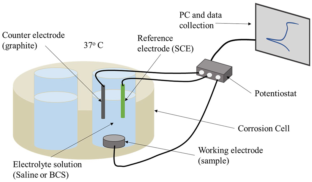
Schematic diagram depicting the custom corrosion cell used for electrochemical testing
Tafel’s methods were used to extrapolate corrosion potential and corrosion current density from the potentiodynamic curve constructed using the CP data. Passivation potential and passive corrosion density were also extrapolated from the potentiodynamic curve.
2.8. Statistical Analysis
Statistical analysis was performed using sigma plot software (version 14) with an alpha value of 0.05. One-way analysis of variance (ANOVA) testing was used to identify significant differences between the CM-Ti6Al4V, SLM-EDM and SLM-printed surfaces within both saline and BCS solution. As part of the analysis, a Shapiro–Wilk test was used to assess the normality of the data set and Brown–Forsythe test determined whether the data were of equal variance. Data passing the normality test were analyzed using a Tukey test while data that failed the normality test was analyzed using a Kruskal–Wallis test.
Paired T-tests were used to assess the effect of saline and BCS solutions. Again, a Shapiro–Wilk test and Brown–Forsythe test respectively were used to assess the normality and equality of variance of the dataset. p values are reported in Table 1 with significant differences (p < 0.05) in bold.
Table 1.
Summary of electrochemical data
| CM-Ti6Al4V |
SLM-EDM |
SLM-printed |
Saline inter-surface comparisons |
BCS inter-surface comparisons |
||||||||
|---|---|---|---|---|---|---|---|---|---|---|---|---|
| Saline | BCS | Saline | BCS | Saline | BCS | CM-Ti6Al4V vs. SLM-EDM | CM-Ti6Al4V vs. SLM-printed | SLM-EDM vs. SLM-printed | CM-Ti6Al4V vs. SLM-EDM | CM-Ti6Al4V vs. SLM-printed | SLM-EDM vs. SLM-Printed | |
| OCPa | ||||||||||||
| OCP (V) | − 0.376 ± 0.016 | − 0.434 ± 0.063 | − 2.82 ± 0.023 | − 0.459 ± 0.043 | 0.043 ± 0.016 | − 0.108 ± 0.021 | ||||||
| Inter-solution comparisons | p = 0.202 | p = 0.003 | p < 0.001 | |||||||||
| Inter-surface comparisons | p = 0.002 | p < 0.001 | p < 0.001 | p = 0.786 | p < 0.001 | p < 0.001 | ||||||
| EISb | ||||||||||||
| Resistance (MΩ) | 11.037 ± 1.108 | 23.497 ± 15.123 | 19.980 ± 8.697 | 20.163 ± 3.823 | 4.208 ± 2.580 | 17.747 ± 2.562 | ||||||
| Inter-solution comparison | p = 0.228 | p = 0.975 | p = 0.003 | |||||||||
| Inter-surface comparisons | p = 0.175 | p = 0.322 | p = 0.025 | p = 0.751 | p = 0.751 | p = 0.751 | ||||||
| Capacitance (μF) | 15.793 ± 1.430 | 12.848 ± 5.716 | 15.460 ± 1.169 | 16.840 ± 1.107 | 20.193 ± 2.205 | 21.780 ± 1.479 | ||||||
| Inter-solution comparison | p = 0.435 | p = 0.211 | 0.359 | |||||||||
| Inter-surface comparisons | p = 0.966 | p = 0.040 | p = 0.030 | p = 0.053 | p = 0.053 | p = 0.053 | ||||||
| Cyclic polarizationc | ||||||||||||
| Ecorr (V) | − 0.602 ± 0.039 | − 0.706 ± 0.016 | − 0.555 ± 0.052 | − 0.667 ± 0.054 | − 0.209 ± 0.053 | − 0.445 ± 0.129 | ||||||
| Inter-solution comparison | p = 0.013 | p = 0.100 | p = 0.043 | |||||||||
| Inter-surface comparisons | p = 0.736 | p = 0.045 | p = 0.229 | p = 0.832 | p = 0.018 | p = 0.036 | ||||||
| 0.022 ± 0.009 | 0.019 ± 0.007 | 0.021 ± 0.006 | 0.024 ± 0.007 | 0.056 ± 0.014 | 0.038 ± 0.013 | |||||||
| p = 1.000 | p = 0.374 | p = 0.150 | ||||||||||
| p = 0.071 | p = 0.071 | p = 0.071 | p = 0.256 | p = 0.256 | p = 0.256 | |||||||
| Epass (V) | 0.493 ± 0.046 | 0.377 ± 0.257 | 0.988 ± 0.046 | 0.697 ± 0.036 | 0.817 ± 0.033 | 0.664 ± 0.004 | ||||||
| Inter-solution comparison | p = 0.487 | p < 0.001 | p < 0.001 | |||||||||
| Inter-surface comparisons | p < 0.001 | p < 0.001 | p = 0.006 | p = 0.382 | p = 0.382 | p = 0.382 | ||||||
| Ipass (μA/cm2) | 6.909 ± 1.100 | 5.376 ± 2.009 | 11.008 ± 0.984 | 9.657 ± 1.358 | 8.878 ± 0.913 | 8.515 ± 0.992 | ||||||
| Inter-solution comparison | p = 0.312 | p = 0.400 | p = 0.668 | |||||||||
| Inter-surface comparisons | p = 0.006 | p = 0.116 | p = 0.090 | p = 0.031 | p = 0.097 | p = 0.647 | ||||||
Displays data from open circuit potential (OCP) assay including raw data values and p-values for both inter-solution and inter-surface comparisons
Displays data from electrical impedance spectroscopy (EIS) assay including raw data values and p-values for both inter-solution and inter-surface comparisons
Displays data from cyclic polarization assay including raw data values and p-values for both inter-surface and inter-solution comparisons
3. Results
3.1. Surface Analysis
Figure 2 presents the 3D images of specimen surfaces from white light interferometry. The SLM-printed surface shows rough and irregular morphology. Due to the polishing process, the SLM-EDM and CM-Ti6Al4V samples exhibit more smooth, uniform surfaces. The surface roughness (Ra) values are 14.82 μm, 0.13 μm and 0.1 μm for SLM-printed, SLM-EDM and CM-Ti6Al4V groups, respectively.
Fig. 2.
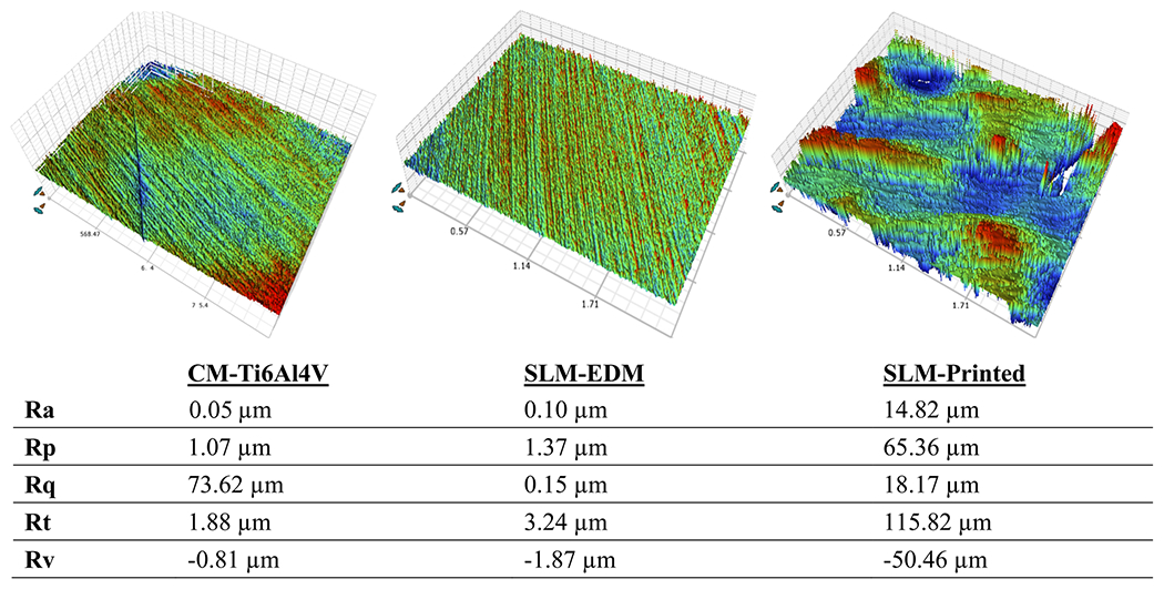
White light interferometry images of CM-Ti6Al4V, SLM-EDM and SLM-printed surfaces with corresponding surface roughness data. Mean height of surface (Ra), maximum profile peak height (Rp), root mean square of surface profile (Rq), total height of surface profile (Rt), maximum profile valley depth (Rv)
The surfaces were further examined by SEM analysis after corrosion experiments. As seen in Fig. 3, no meaningful corrosive patterns were observed. There were some cracks noted in the SLM-printed surface; however, it is not clear whether these were a consequence of the manufacturing process or due to corrosion.
Fig. 3.
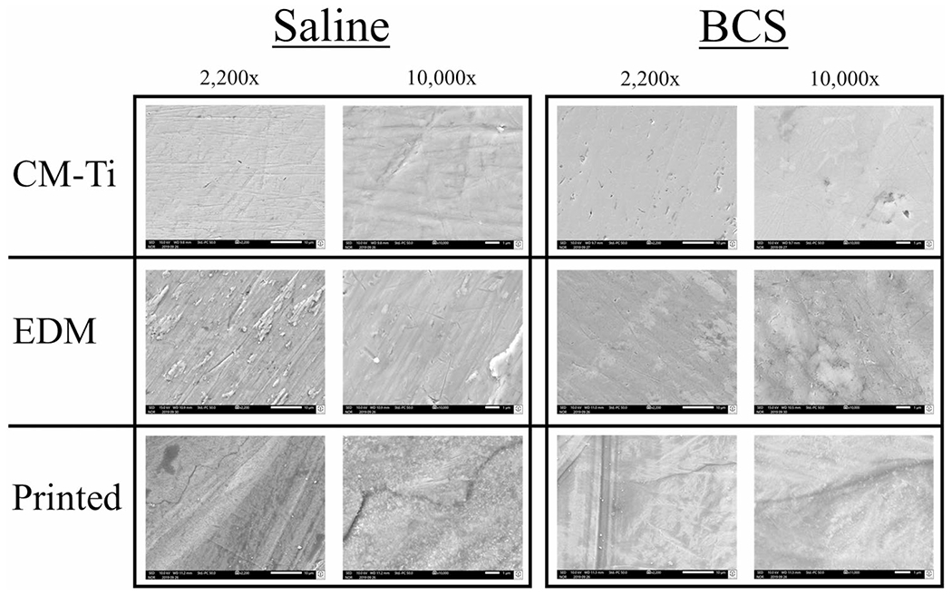
SEM images of exposed experimental surface at 2200 × and 10,000 × magnification in saline and BCS solutions
3.2. Alloy Microstructure
The CM-Ti6Al4V wrought alloy consisted of fine equiaxed grains of mostly α phase and dispersed β phase with a total volume fraction of 5%. The grain size—as measured by the equivalent circle diameter (ECD)—was 1.08 ± 0.78 μm and the average aspect ratio was 2.2. The chemical distribution was slightly inhomogeneous with a higher aluminum content and lower vanadium content in the α phase compared to the β phase. SLM-Ti6Al4V alloy exhibited a typical martensitic microstructure of needle-like grains (Fig. 4). The grain size—as measured by the ECD—was 1.65 ± 0.37 μm, the lath width was 0.96 ± 0.6. μm, the average grain aspect ratio was 3.1, and the volume fraction of β phase less than 0.2%. The microstructure also exhibited a homogeneous distribution of all alloying elements, numerous characteristic voids due to lack of fusion as well as the residual grain structure of prior β grains as previously described [18] (Fig. 4).
Fig. 4.
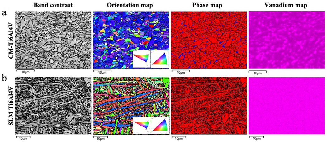
Band contrast, orientation map (inverse pole figure—IPF), phase map (red = α, blue = β phase) and vanadium map of the (a) CM-Ti6Al4V and (b) SLM Ti6Al4V. A fine microstructure of equiaxed grains with β phase distributed as isolated islands along the boundaries of α phase, matching with a higher vanadium concentration was observed on (a) CM-H6A14V; while (b) SLM-H6A14V had a needle-like microstructure, characteristic for α′ martensite, with a homogeneous distribution of its alloying elements here represented by the vanadium map. The black lines represent the grain boundaries on band contrast, orientation map and phase map (Color figure online)
3.3. OCP Data
OCP values are described in Table 1 and OCP curves are shown in Fig. 5. The unpolished SLM-printed surfaces stratified independently demonstrating significantly more positive OCPs compared to the polished SLM-EDM and CM-Ti6Al4V surfaces (SLM-printed in saline 0.043 ± 0.016 V vs. SLM-EDM in saline – 0.282 ± 0.023 V, p < 0.001; SLM-printed in saline 0.043 ± 0.016 V vs. CM-Ti6Al4V in saline – 0.376 ± 0.016 V, p < 0.001; SLM-printed in BCS – 0.108 ± 0.021 V vs. SLM-EDM in BCS – 0.459 ± 0.043 V, p < 0.001; SLM-printed in BCS – 0.108 ± 0.021 V vs. CM-Ti6Al4V in BCS – 0.434 ± 0.063 V, p < 0.001). BCS solution appeared to negatively impact OCP across all surfaces relative to their saline counterparts; however, significant differences were only found in the SLM surfaces (SLM-EDM in saline – 0.282 ± 0.023 V vs. SLM-EDM in BCS – 0.459 ± 0.043 V, p = 0.003; SLM-printed in saline 0.043 ± 0.016 V vs. SLM-printed in BCS – 0.108 ± 0.021 V, p < 0.001).
Fig. 5.
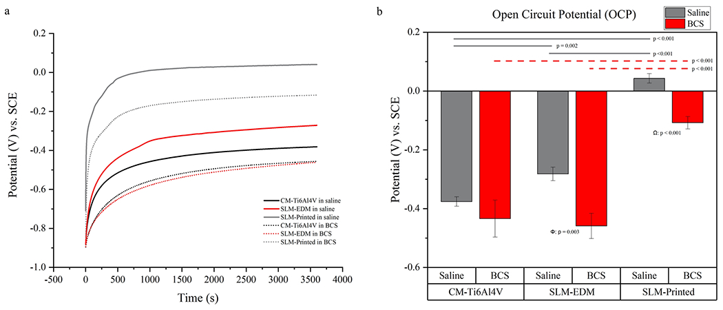
(a) OCP curves of CM-Ti6Al4V, SLM-EDM and SLM-printed surfaces in saline and BCS. (b) Bar graph of OCP values. Horizontal lines highlight significant inter-surface differences. Δ compares CM-Ti6Al4V in saline vs. CM-Ti6Al4V in BCS, Φ compares SLM-EDM in saline vs. SLM-EDM in BCS, Ω compares SLM-printed in saline vs. SLM-printed in BCS
3.4. EIS Data
Figure 6 represents the electrical equivalent circuit (EEC) used to fit the EIS data for all surfaces using Gamry Echem Analyst software. The proposed EEC assumes two sources of resistance: the resistance of solution (Ru) and the resistance of the passive film (Rp). The model also incorporates a constant phase element (CPE) representing the imperfect capacitance of the passive film that is arranged in parallel with Rp. EIS data are presented in Table 1 and impedance is represented as Bode and Nyquist plots in Figs. 7 and 8, respectively.
Fig. 6.
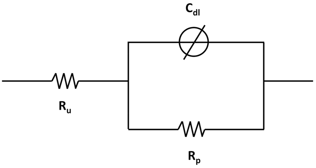
EEC model used for fitting the EIS data, where Ru is the resistance of the solution, Rp is the resistance of the passive film and Cdl is the imperfect capacitance, or constant phase element, of the passive film
Fig. 7.
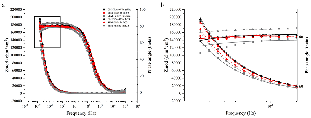
(a) Bode plot of EIS data with modeled curves. (b) Zoomed image of boxed area of bode plot
Fig. 8.
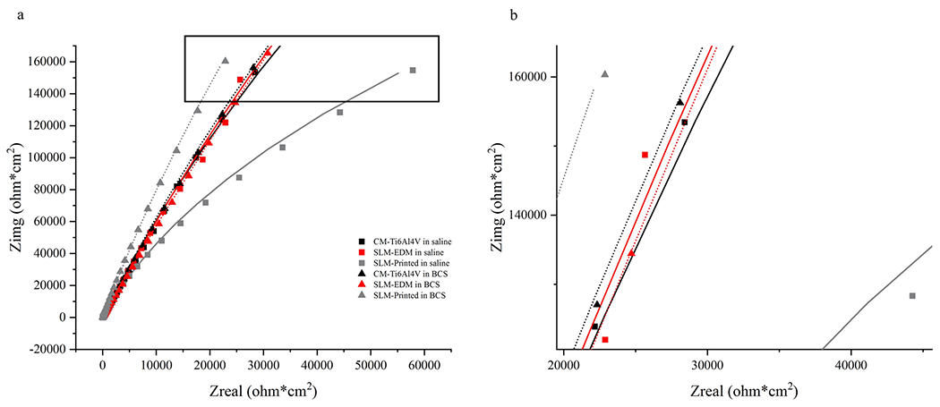
(a) Nyquist plot of EIS data with modeled curves. (b) Zoomed image of boxed area of Nyquist plot
All surfaces had similar impedance and phase angle plots as seen in the Nyquist and Bode curves, suggesting a similar corrosion kinetics profile. The SLM-printed surface displayed the highest capacitance values, regardless of solution; however, significant differences were only observed the saline solution (SLM-printed in saline 20.193 ± 2.205 μF vs. SLM-EDM 15.460 ± 1.169 μF, p = 0.03; SLM-printed in saline 20.193 ± 2.205 μF vs. CM-Ti6Al4V in saline 15.793 ± 1.430, p = 0.04). Interestingly, as seen in Fig. 9a, the SLM-printed surface demonstrated a significant increase in resistance in BCS relative to saline (SLM-printed in saline 4.208 ± 2.580 MΩ vs. SLM-printed in BCS 17.747 ± 2.562 MΩ, p = 0.003) that was not present in the SLM-EDM surface. The CM-Ti6Al4V did demonstrate an increase in resistance though not within the realm of significance. This observation is unexpected as the trend of the corrosion potential was to decrease from saline to BCS, which would tend to suggest a lower resistance of the passive film.
Fig. 9.
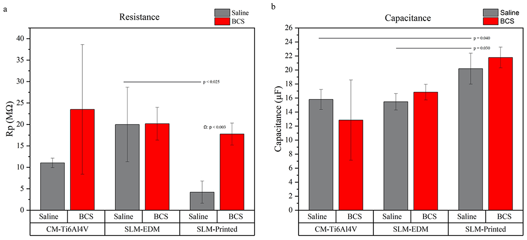
(a) Bar graph representing resistance values. (b) Bar graph representing capacitance values. Horizontal lines highlight significant inter-surface differences. Δ compares CM-Ti6Al4V in saline vs. CM-Ti6Al4V in BCS, Φ compares SLM-EDM in saline vs. SLM-EDM in BCS, Ω compares SLM-printed in saline vs. SLM-printed in BCS
3.5. Potentiodynamic Data
Potentiodynamic data can be found in Table 1 and potentiodynamic curves can be seen in Fig. 10. Ecorr and Icorr values were calculated via Tafel’s extrapolation and are represented graphically in Fig. 11. Similar to OCP data, Ecorr values demonstrated the most noble behavior in the SLM-printed surface while decreasing across all surfaces in BCS relative to saline with significant differences noted in the CM-Ti6Al4V and SLM-printed surfaces (CM-Ti6Al4V in saline – 0.602 ± 0.039 V vs. CM-Ti6Al4V in BCS – 0.706 ± 0.016 V, p = 0.013; SLM-printed in saline – 0.209 ± 0.053 V vs. SLM-printed in BCS −0.445 ± 0.129 V, p = 0.043).
Fig. 10.
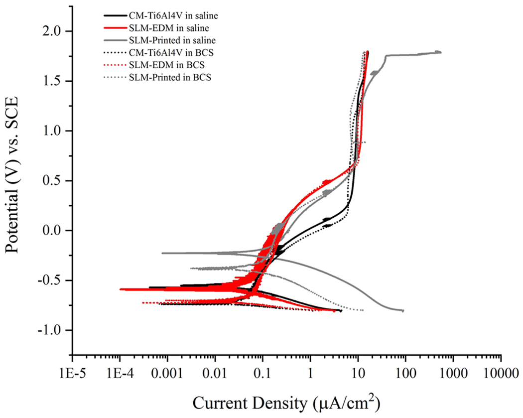
Potentiodynamic curves of CM-Ti6Al4V, SLM-EDM and SLM-printed surfaces in saline and BCS
Fig. 11.
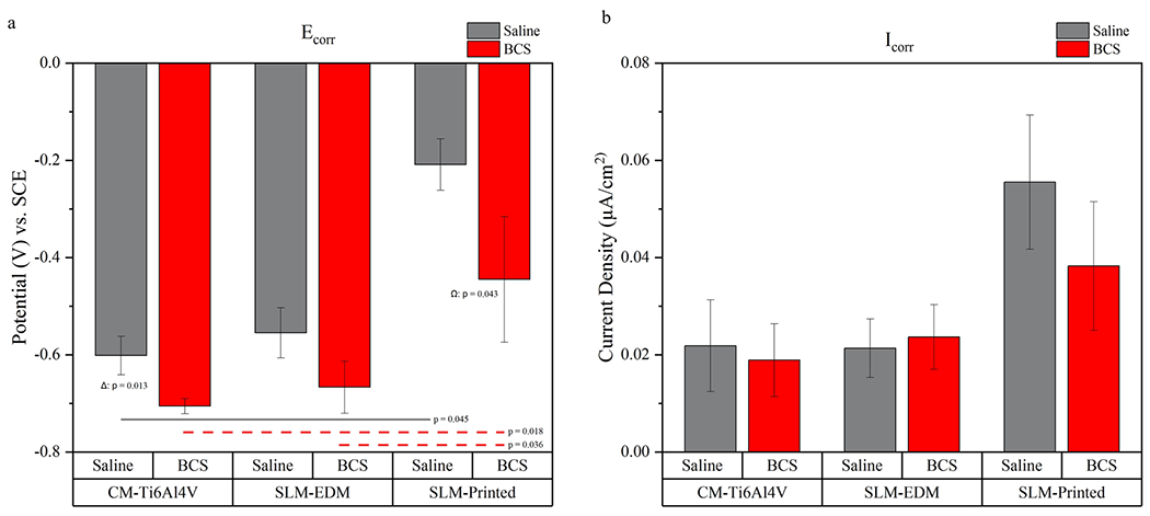
(a) Bar graph representing Ecorr values. (b) Bar graph representing Icorr values. Horizontal lines highlight significant inter-surface differences. Δ compares CM-Ti6Al4V in saline vs. CM-Ti6Al4V in BCS, Φ compares SLM-EDM in saline vs. SLM-EDM in BCS, Ω compares SLM-printed in saline vs. SLM-printed in BCS
While BCS seemed to have the modest, undesirable effect of lowering corrosion potential relative to the saline solution, there was little to no effect on Icorr which remained stable and no statistical differences were observed between surfaces or solutions. As seen in Fig. 11b, the SLM-Printed surface demonstrated the greatest corrosion current densities (0.056 ± 0.014 μA/cm2 in saline; 0.038 ± 0.013 μA/cm2 in BCS) while the SLM-EDM (0.021 ± 0.061 μA/cm2 in saline; 0.024 ± 0.007 ±A/cm2 in BCS) and CM-Ti6Al4V (0.022 ± 0.009 μA/cm2 in saline; 0.019 ± 0.007 μA/cm2 in BCS) surfaces were more comparable. Additionally, though outside the level of significance, a substantial drop in corrosion density was observed in the SLM-printed surface moving from saline to BCS solution. Both of these findings were likely contributed to by the increased surface roughness of the SLM-printed surface.
Passivation potential and passivation current density are represented graphically in Fig. 12. Passivation potentials were increased in both SLM surfaces relative to the CM-Ti6Al4V surface, highlighting a significant delay in passivation behavior in both saline and BCS solutions (CM-Ti6Al4V in saline 0.493 ± 0.046 V vs. SLM-EDM in saline 0.988 ± 0.046 V, p = < 0.001; CM-Ti6Al4V in saline 0.493 ± 0.046 V vs. SLM-printed in saline 0.817 ± 0.033 V, p = < 0.001; CM-Ti6Al4V in BCS 0.377 ± 0.257 V vs. SLM-EDM in BCS 0.697 ± 0.036 V, p = 0.031).
Fig. 12.
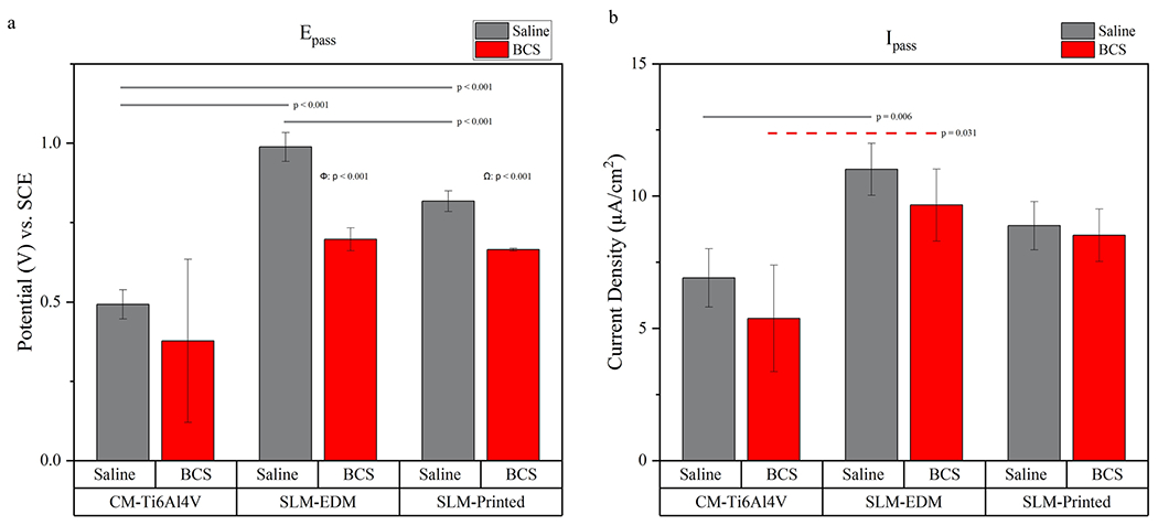
(a) Bar graph representing Ecorr values. (b) Bar graph representing Icorr values. Horizontal lines highlight significant inter-surface differences. Δ compares CM-Ti6Al4V in saline vs. CM-Ti6Al4V in BCS, Φ compares SLM-EDM in saline vs. SLM-EDM in BCS, Ω compares SLM-printed in saline vs. SLM-Printed in BCS
Passivation current densities were increased in the SLM surfaces compared to the CM-TiAl4V controls; however, significant differences were only detected between the CM-Ti6Al4V and SLM-EDM surfaces (CM-Ti6Al4V in saline 6.909 ± 1.100 μA/cm2 vs. SLM-EDM in saline 11.008 ± 0.984 μA/cm2, p = 0.006; CM-Ti6Al4V in BCS 5.376 ± 2.009 vs. SLM-EDM in BCS 9.657 ± 1.358 μA/cm2, p = 0.031).
4. Discussion
This study analyzes the corrosion behavior of SLM-Ti6Al4V. Samples were assessed in both saline and BCS solutions to simulate environments commonly found in vivo. AM techniques are revolutionizing biomedical implants by creating an almost infinite degree of personalization of the implant for the patient as well as creating the ability to incorporate complex lattice structures and control porosity to maximize biocompatibility and longevity.
There have been many previous studies comparing AM-Ti6Al4V to commercially pure titanium or commercially cast or wrought titanium alloys; however, none have done an intra-material comparison examining how the unmodified SLM-printed surface behaves relative with the cut surface of the material. This allows us to separate trends that are related to the compositional makeup of the material from those that are related to the character of the build surface. Furthermore, incorporating BCS solution provides insight into how proteins interact and influence SLM surfaces.
4.1. Surface Comparisons
SLM-printed surfaces performed very differently from the polished SLM-EDM and CM-Ti6Al4V surfaces in both saline and BCS, displaying greater corrosion potentials and current densities. This suggests that there is an inherent resistance to corrosion, likely due to a pre-existing, thick oxide layer that is lost with post-manufacture polishing protocols as evidenced by the lower corrosion potential of the polished SLM-EDM surface but also indicates that this surface corrodes at an increased corrrosion rate. The SLM-printed surface was not polished and was found to have average Ra value of 14.816 μm whereas the polished SLM-EDM and CM-Ti6Al4V surfaces had Ra values of 0.102 μm. This could explain the increased corrosion current densities relative to the EDM surface by creating a greater surface area for which corrosion to occur [28,29].
As seen in the potentiodynamic curve (Fig. 10), SLM-EDM and CM-Ti6Al4V surfaces initially stratified by solution, demonstrating similar Ecorr and Icorr; however, as voltage increased, passivation began stratifying by surface. This suggests that Ecorr and Icorr are more influenced by their environment (saline or BCS) whereas passivation behavior is more a function of alloy microstructure (homogeneous vs. inhomogeneous chemical distribution, α/β vs. α’).
4.2. Influence of Microstructure on Passivation Behavior
It has been shown that AM techniques produce materials with different microstructures than traditionally wrought or cast materials that can alter corrosion behavior. For instance, faster cooling rates in SLM produce a microstructure dominated by an α′ martensitic phase compared to traditionally wrought or cast titanium that display a mixed α/β phase microstructure [15–17]. Meanwhile, Zhao et al. demonstrated that SLM and EBM materials have different proportions of α to β phase and consequently behave differently in different environments [19].
The SLM-Ti6Al4V surface demonstrated an abundance of α’ martensitic phase, while the CM-Ti6Al4V surface was shown to exhibit a dispersion of fine β phase within an α matrix consistent with current literature [15–17,19–21], Increased vanadium content in the β phase has been shown to stabilize formation of the oxide layer while the α phase is more vulnerable to selective dissolution [30]. It is therefore reasonable to conclude that microstructural differences between SLM materials and traditional wrought or cast materials may be affecting the stability of the oxide layer and consequently, influencing passivation behavior. This would explain the reduction of the passive range and the elevated passivation current densities present in the SLM-Ti6Al4V. These findings were consistently found when comparing both SLM surfaces to the CM-Ti6Al4V control indicating that surface roughness and a pre-existing oxide layer had a little impact on this phenomenon and rather that it is an inherent quality of the SLM material’s composition. However, these factors cannot be completely disregarded as a significant difference in passivation potential was observed between the SLM-printed and SLM-EDM surfaces in saline.
4.3. Effect of Protein on Corrosion and Passivation Behavior
The overall effect of BCS was to decrease potential differences. All parameters that analyzed potential ratings including OCP, Ecorr and Epass decreased in BCS relative to saline across all surfaces. This effect was most pronounced in the SLM surfaces where statistical differences were observed in all but the Ecorr value of the SLM-EDM surface. Comparatively, the CM-Ti6Al4V surface only saw a statistically significant change in its Ecorr value. However, it should also be noted that outlying data within the SLM-BCS group is likely contributing to the lack of statistically significant differences between the SLM and CM-Ti6Al4V surfaces in BCS by inflating the standard deviation and making meaningful differences more difficult to detect.
The trends seen in the SLM-printed surface suggest that the impact of proteins on corrosion processes can be amplified with increased surface roughness. This makes sense as proteins assert their effects largely through adsorption onto the metallic surface, and increased surface roughness has been shown to be associated with increased protein adsorption due to simple spatial effect of a larger area existing within the same two-dimensional space [31,32]. As discussed previously, surfaces in BCS displayed a ubiquitous trend of decreasing potential, evidenced by lower OCP, corrosion and passivation potentials relative to their saline counterparts; however, the changes were most pronounced in the SLM-printed surface which had over 100x greater surface roughness than the polished SLM-EDM and CM-Ti6Al4V surfaces. Also, while not within the realm of significance, a modest decrease in the corrosion current density was observed in the SLM-printed surface in BCS relative to saline, whereas it remained relatively stable in the SLM-EDM and CM-Ti6Al4V surfaces (Fig. 10b). This suggests that proteins may also influence the corrosion rate in situations with increased protein adsorption. This is consistent with the current literature which suggests that proteins can have both detrimental and protective effects on the corrosion behavior of a metallic surface. Adsorption of proteins can alter the surface chemistry of metallic surface and the passive oxide film in a variety of ways. They can also influence surface corrosion reactions by chelating metal ions, serving as electron acceptors and acting as an additional non-conductive barrier between the surface and the solution diminishing current flow [32–35]. Therefore, it is reasonable to conclude that protein interactions at the metallic surface and with the passive film are modifying the surface chemistry, resulting in the observed decrease in corrosion potential across all surfaces. In the SLM-printed surface, the increased volume of protein adsorption could also be sufficient to influence current density, possibly by creating a second non-conductive layer between the metallic surface and the solution.
4.4. Figure 4.4 Summary of Corrosion Behavior
Figure 13 is a schematic diagram summarizing the different corrosion behavior observed between different surfaces and solutions. CM-Ti6Al4V and SLM-EDM surfaces were both polished to a mirror surface. This process removed any pre-existing passive layer on the surface, resulting in only a thin passive film, whereas the unpolished SLM-Printed surface likely maintained a thick pre-existing passive film. This explains the more noble corrosion potentials of the SLM-printed surface. In BCS, a similar pattern was observed, but corrosion potential decreased across all surfaces likely due to an altered surface chemistry created by the adsorption of proteins. Both SLM-EDM and SLM-printed surfaces demonstrated delays in passivation due to increased α phase microstructure. This effect was amplified by the presence of protein in BCS solution. The SLM-printed surface’s increased surface roughness and resultant increased surface area contributed to greater corrosion current densities as well as greater differences between saline and BCS secondary to increased protein adsorption.
Fig. 13.
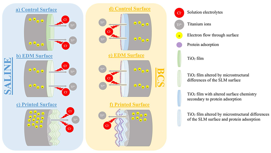
Graphical summary of electrochemical processes. (a) Representative image of CM-Ti6Al4V corrosion behavior in saline. (b) Representative image of SLM-EDM corrosion behavior in saline. Performed similar to CM-Ti6Al4V except for passivation behavior which was delayed. (c) Representative image of SLM-printed surface in saline. Exhibited greater Ecorr and OCP values due to thicker oxide layer unmodified by polishing as well as greater Icorr values due to the increased surface roughness. (d) Representative image of CM-Ti6Al4V corrosion behavior in BCS. Protein adsorption altered the surface chemistry of the TiO2 layer lowering Ecorr and OCP values relative to saline. (e) Representative image of SLM-EDM corrosion behavior in BCS. Passivation behavior was further delayed due to combination of protein adsorption and altered microstructure. Ecorr decreased comparably to the CM-Ti6Al4V surface. (f) Representative image of SLM-printed corrosion behavior in BCS. Further delay of passivation as seen in SLM-EDM surface. Icorr decreased relative to SLM-printed in saline possibly due to greater protein content at the surface affecting current flow
4.5. Clinical Relevance
SLM-EDM and CM-Ti6Al4 performed similarly in regards to their corrosion potential and current density, revealing no meaningful differences in corrosion resistance or rate between the two manufacturing methods. However, meaningful differences were observed in passivation behavior, suggesting that the passive film is less stable in the SLM-produced Ti6Al4V. Titanium’s passivation behavior confers many of its attractive qualities as an orthopedic implant material. Therefore, disruption of this behavior could have consequences for its performance in vivo.
Furthermore, assuming no post-manufacturing protocols, the behavior of the SLM-printed surface is the most relevant to how the material will behave. While it did display superior corrosion potential relative to the other surfaces, it also displayed elevated corrosion current densities, suggesting an elevated corrosion rate. Additionally, its increased surface roughness amplified the effects of proteins in solution as evidenced by its behavior in BCS. These effects could be further amplified in an even more complex in vivo environment. This study highlights the less stable passive film of SLM-Ti6Al4V and the compounding effects of protein adsorption, suggesting SLM-Ti6Al4V implants may be more prone to corrosion. However, this effect has not been sufficiently quantified and the added benefits of AM implants may still provide a net benefit to implant performance.
4.6. Limitations and Future Work
While this study does bring to light interesting and meaningful differences between SLM and CM-Ti6Al4V and their behaviors in saline and BCS solutions, we do acknowledge several limitations. Firstly, there are many different methods of AM and varying parameters within these methods. We cannot extrapolate this data with any certainty to be applicable to AM-Ti6Al4V manufactured from different methods or settings. Furthermore, while we do attempt to broaden the corrosion environment to include not only saline but BCS as well, we acknowledge that BCS is a simple protein solution and still dissimilar from the complex environment within a synovial joint capsule. Due to the diverse AM processes, porosity can be a significant concern; however, in this study we have not examined such effects because of limitations in sample availability. Due to this difference as well as the added component of physical wear within an in vivo joint, we cannot say that our data represent an accurate depiction of SLM-Ti6Al4V corrosion behavior in vivo. Tribocorrosion studies will be an important aspect of future analysis to examine how wear contributes to the corrosion and passivation behavior of SLM-Ti6Al4V.
5. Conclusions
SLM-Ti6Al4V and CM-Ti6Al4V demonstrate similar corrosion behavior when surfaces are equivalent. Lack of polishing in the SLM-printed surface preserves a pre-existing oxide layer increasing corrosion resistance but also results in increased surface roughness elevating corrosion current density and the influence of protein adsorption. Protein adsorption appeared to alter the surface chemistry, resulting in decreased corrosion potential. Microstructural differences between SLM-Ti6Al4V and CM-Ti6Al4V result in a decreased passive range and elevated passive range current densities within the SLM-Ti6Al4V regardless of surface.
Funding
NIH R01 Grant AR070181 (PIs: Lundberg, Mathew, Pourzal), Blazer Foundation, University of Illinois College of Medicine James Scholar Program.
Footnotes
Material Availability Available upon request.
Code Availability Not applicable.
Conflict of interest The authors declare that they have no conflict of interest.
Ethical Approval Not applicable.
Consent to Participate Not applicable.
Consent for Publication Not applicable.
Data Availability
Available upon request.
References
- 1.Kurtz SM, Ong KL, Lau E, Bozic KJ (2014) Impact of the economic downturn on total joint replacement demand in the United States: updated projections to 2021. J Bone Joint Surg Am 96:624–630 [DOI] [PubMed] [Google Scholar]
- 2.Ravi B et al. (2012) The changing demographics of total joint arthroplasty recipients in the United States and Ontario from 2001 to 2007. Best Pract Res Clin Rheumatol 26:637–647 [DOI] [PubMed] [Google Scholar]
- 3.Bayliss LE et al. (2017) The effect of patient age at intervention on risk of implant revision after total replacement of the hip or knee: a population-based cohort study. The Lancet 389:1424–1430 [DOI] [PMC free article] [PubMed] [Google Scholar]
- 4.Huang H-H (2003) Effect of fluoride and albumin concentration on the corrosion behavior of Ti–6Al–4V alloy. Biomaterials 24:275–282 [DOI] [PubMed] [Google Scholar]
- 5.Guillemot F (2005) Recent advances in the design of titanium alloys for orthopedic applications. Expert Rev Med Devices 2:741–748 [DOI] [PubMed] [Google Scholar]
- 6.Rack HJ, Qazi JI (2006) Titanium alloys for biomedical applications. Mater Sci Eng C 26:1269–1277 [Google Scholar]
- 7.Geetha M, Singh AK, Asokamani R, Gogia AK (2009) Ti based biomaterials, the ultimate choice for orthopaedic implants—a review. Prog Mater Sci 54:397–425 [Google Scholar]
- 8.Srivastav A (2011) An overview of metallic biomaterials for bone support and replacement. Biomed Eng Trends Mater Sci. 10.5772/13488 [DOI] [Google Scholar]
- 9.Bagaria V, Bhansali R, Pawar P (2018) 3D printing-creating a blueprint for the future of orthopedics: current concept review and the road ahead! Journal of Clinical Orthopaedics and Trauma 9:207–212 [DOI] [PMC free article] [PubMed] [Google Scholar]
- 10.Sidambe AT (2014) Biocompatibility of advanced manufactured titanium implants—a review. Materials 7:8168–8188 [DOI] [PMC free article] [PubMed] [Google Scholar]
- 11.Wang X et al. (2016) Topological design and additive manufacturing of porous metals for bone scaffolds and orthopaedic implants: a review. Biomaterials 83:127–141 [DOI] [PubMed] [Google Scholar]
- 12.Zhang L-C, Attar H (2016) Selective laser melting of titanium alloys and titanium matrix composites for biomedical applications: a review. Adv Eng Mater 18:463–475 [Google Scholar]
- 13.Tan XP, Tan YJ, Chow CSL, Tor SB, Yeong WY (2017) Metallic powder-bed based 3D printing of cellular scaffolds for orthopaedic implants: a state-of-the-art review on manufacturing, topological design, mechanical properties and biocompatibility. Mater Sci Eng, C 76:1328–1343 [DOI] [PubMed] [Google Scholar]
- 14.Talib Mohammed M (2018) Mechanical properties of SLM-titanium materials for biomedical applications: a review. Materials Today: Proceedings 5:17906–17913 [Google Scholar]
- 15.Zhao X et al. (2016) Comparison of the microstructures and mechanical properties of Ti–6Al–4V fabricated by selective laser melting and electron beam melting. Mater Des 95:21–31 [Google Scholar]
- 16.Kasperovich G, Haubrich J, Gussone J, Requena G (2016) Correlation between porosity and processing parameters in TiAl6V4 produced by selective laser melting. Mater Des 105:160–170 [Google Scholar]
- 17.Thijs L, Verhaeghe F, Craeghs T, Humbeeck JV, Kruth J-P (2010) A study of the microstructural evolution during selective laser melting of Ti–6Al–4V. Acta Mater 58:3303–3312 [Google Scholar]
- 18.Neto MQ et al. (2021) The effect of additive manufacturing parameters on microstructure and mechanical properties of biomedical grade Ti-6Al-4V alloy. ASTM Selected Technical Papers. 10.1520/STP163720200121 [DOI] [Google Scholar]
- 19.Zhao B, Wang H, Qiao N, Wang C, Hu M (2017) Corrosion resistance characteristics of a Ti-6Al-4V alloy scaffold that is fabricated by electron beam melting and selective laser melting for implantation in vivo. Mater Sci Eng C 70:832–841 [DOI] [PubMed] [Google Scholar]
- 20.Dai N, Zhang L-C, Zhang J, Chen Q, Wu M (2016) Corrosion behavior of selective laser melted Ti-6Al-4V alloy in NaCl solution. Corros Sci 102:484–489 [Google Scholar]
- 21.Toptan F et al. (2019) Corrosion and tribocorrosion behaviour of Ti6Al4V produced by selective laser melting and hot pressing in comparison with the commercial alloy. J Mater Process Technol 266:239–245 [Google Scholar]
- 22.de Damborenea JJ et al. (2017) Corrosion of Ti6Al4V pins produced by direct metal laser sintering. Appl Surf Sci 393:340–347 [Google Scholar]
- 23.Mathew MT, Jacobs JJ, Wimmer MA (2012) Wear-corrosion synergism in a CoCrMo hip bearing alloy is influenced by proteins. Clin Orthop Relat Res 470:3109–3117 [DOI] [PMC free article] [PubMed] [Google Scholar]
- 24.Royhman D et al. (2021) Fretting-corrosion in hip taper modular junctions: The influence of topography and pH levels —an in-vitro study. J Mech Behav Biomed Mater 118:104443. [DOI] [PMC free article] [PubMed] [Google Scholar]
- 25.Panigrahi P et al. (2014) Intergranular pitting corrosion of CoCrMo biomedical implant alloy. J Biomed Mater Res B Appl Biomater 102:850–859 [DOI] [PubMed] [Google Scholar]
- 26.Abey S et al. (2014) Electrochemical behavior of titanium in artificial saliva: influence of pH. J Oral Implantol 40:3–10 [DOI] [PubMed] [Google Scholar]
- 27.G01 Committee. Test method for conducting cyclic potentiodynamic polarization measurements for localized corrosion susceptibility of iron-, nickel-, or cobalt-based alloys. http://www.astm.org/cgi-bin/resolver.cgi?G61-86R18. 10.1520/G0061-86R18. [DOI]
- 28.Walter R, Kannan MB (2011) Influence of surface roughness on the corrosion behaviour of magnesium alloy. Mater Des 32:2350–2354 [Google Scholar]
- 29.Yoo B, Shin KR, Hwang DY, Lee DH, Shin DH (2010) Effect of surface roughness on leakage current and corrosion resistance of oxide layer on AZ91 Mg alloy prepared by plasma electrolytic oxidation. Appl Surf Sci 256:6667–6672 [Google Scholar]
- 30.Chen J-R, Tsai W-T (2011) In situ corrosion monitoring of Ti–6Al–4V alloy in H2SO4/HCl mixed solution using electrochemical AFM. Electrochim Acta 56:1746–1751 [Google Scholar]
- 31.Eliaz N (2019) Corrosion of metallic biomaterials: a review. Materials (Basel) 12:407. [DOI] [PMC free article] [PubMed] [Google Scholar]
- 32.Silva-Bermudez P, Rodil SE (2013) An overview of protein adsorption on metal oxide coatings for biomedical implants. Surf Coat Technol 233:147–158 [Google Scholar]
- 33.Hedberg Y et al. (2013) Surface-protein interactions on different stainless steel grades: effects of protein adsorption, surface changes and metal release. J Mater Sci: Mater Med 24:1015–1033 [DOI] [PMC free article] [PubMed] [Google Scholar]
- 34.Hedberg Y, Karlsson M-E, Blomberg E, Odnevall Wallinder I, Hedberg J (2014) Correlation between surface physicochemical properties and the release of iron from stainless steel AISI 304 in biological media. Colloids Surf B: Biointerfaces 122:216–222 [DOI] [PubMed] [Google Scholar]
- 35.Khan MA, Williams RL, Williams DF (1999) The corrosion behaviour of Ti–6Al–4V, Ti–6Al–7Nb and Ti–13Nb–13Zr in protein solutions. Biomaterials 20:631–637 [DOI] [PubMed] [Google Scholar]
Associated Data
This section collects any data citations, data availability statements, or supplementary materials included in this article.
Data Availability Statement
Available upon request.


