

Abstract
Access to high-quality MR exams is severely limited for patients with some implanted devices due to labeled MR safety conditions, but small-bore systems can overcome this limitation. For example, a compact 3T MR scanner (C3T) with high-performance gradients can acquire exams of the head, extremities, and infants. Because of its reduced bore size and the patient being advanced only partially into the bore, the associated electromagnetic (EM) fields drop off rapidly caudal to the head, compared to whole-body systems. Therefore, some patients with MR conditional implanted devices can safely receive 3T brain exams on the C3T using its strong gradients and a multiple-channel receive coil, while a corresponding exam on whole-body MR is precluded. The purpose of this study is to evaluate the performance of a small-bore scanner for subjects with MR conditional spinal or sacral nerve stimulators, or abandoned cardiac implantable electronic device (CIED) leads. The spatial dependence of specific absorption rate (SAR) on the C3T was compared to whole-body scanners. A device assessment tool was developed and applied to evaluate MR safety individually on the C3T for 12 subjects with implanted devices or abandoned CIED leads. Once MR safety was established, the subjects received a C3T brain exam along with their clinical, 1.5T exam. The resulting images were graded by three board-certified neuroradiologists. The C3T exams were well-tolerated with no adverse events, and significantly outperformed the whole-body 1.5T exams in terms of overall image quality.
Keywords: Compact 3T, MR safety, implanted device, abandoned lead, spinal stimulator, sacral stimulator
1. INTRODUCTION
A continuing medical need for patients with implanted devices is safe access to MR imaging [1–3]. Patients with MR conditional implanted devices can be safely imaged provided the specified conditions for safe scanning are met. These conditions are specified in device manufacturers’ labeled instructions for use and are frequently also compiled on MR safety websites (e.g., MagResource [4] and MRISafety.com [5]). Measured parameters that form the basis for the conditions for safe scanning [1] include: maximal main magnetic field strength (B0), maximal spatial gradient (dB0/dz), RF heating as measured by maximal specific absorption rate (SAR) or alternatively B1+rms, maximal gradient slew rate (SR), and the type of RF transmit coil (e.g., no restriction with whole-body transmit allowed, or restricted to a local transmit/receive (T/R) head or extremity coil). The conditions sometimes vary depending on the relative location of the device and the landmark position, e.g., the Medtronic InterStim [6]. Numerous MR conditional devices are labeled for use at 1.5T, with fewer labeled for use at 3T.
Diagnostic power of brain imaging limited to 1.5T by MR conditions is clinically suboptimal compared to 3T and higher field strengths [7]. Moreover, the device labeling sometimes restricts the exams to a single-channel, T/R coil to limit the RF power deposition over the device (e.g., comprising an implantable pulse generator (IPG) and leads), which further reduce SNR. Restriction to T/R coils also precludes the use of parallel imaging [8,9] which requires a multi-channel receive coil. While increasing the acquisition time can compensate for the loss of SNR, the MR conditional labeling of many devices imposes total imaging time restrictions (e.g., a 30-minute scanning session time limit restriction for a Nevro spinal cord stimulator [10]). Depending on the vendor, these time limits are specified differently (e.g., continuous scan time versus active gradient time within a certain window). Also, an increase in acquisition time can result in the exam being less well-tolerated for patients, as well as increasing motion-related image artifacts.
Small-bore systems [11,12] and inserts [13–15] are gaining considerable interest due to their higher gradient efficiency. Notably, gradient inductance scales as the fifth power of radius [16,17], and the resulting dramatic reduction for small bore systems improves slew rate efficiency and reduces overall power consumption for small bore systems.
The compact 3T (C3T) MRI [18] scanner is a technology demonstrator developed under NIH-funded programs. The C3T is smaller than a conventional whole-body scanner, with a 42 cm inner diameter gradient coil yielding a 37 cm diameter bore with a 60 cm diameter shoulder cutout. The C3T generates 80 mT/m and 700 T/m/s peak gradient amplitude and slew rate, respectively, which compares to 50 mT/m and 200 T/m/s for a typical 60 cm bore, whole-body system. Also, due to its smaller diameter gradient coil, peripheral nerve stimulation on the C3T is rarely a concern and is easily managed, even at peak gradient performance [19,20]. Besides gradient performance, other advantages of the compact design have been reported previously [18], including a smaller extent of stray B0 fields and easier siting. In this paper, we explore the further advantage of small-bore systems for scanning patients with implanted devices. Some preliminary work was reported at conference presentations [21–25].
In this paper, we investigate three types of implanted device systems including spinal stimulators, sacral nerve stimulators, and abandoned cardiac implantable electronic devices (CIED) leads. These implants are all highly prevalent, so improving image quality for these brain exams is of clinical interest. First, it is estimated that approximately 300,000 sacral nerve simulators have been implanted worldwide [26] with that number expected to increase because approximately 13 million Americans [27] suffer from urinary incontinence. Second, it is estimated that 25,000 spinal cord stimulators have been implanted annually in the U.S. [28], due to 23% of the population suffering from chronic lower back pain [29], including the cohort with failed back surgery syndrome. Finally, 1.2–1.4 million CIEDs have been implanted annually [30]. According to a 10-year study performed at our institution, 8.4% of CIED patients who received an MRI exam had abandoned leads in place [31].
The overall purpose of this study is to evaluate the performance of a small-bore scanner by assessing the relevant electromagnetic fields for each subject to establish MR safety of a brain exam on the C3T, then to compare the resulting images systematically with those obtained with a clinical, whole-body 1.5T scanner, which was the only type of scanner that the device labeling specified as MR conditional.
2. MATERIALS AND METHODS
2.1. Subjects
Under an IRB-approved protocol, 12 subjects were recruited after obtaining informed written consent. The subjects were patients with an implanted device who were either scheduled to receive a clinical 1.5T brain exam or who had received one at our institution within a previous one-year period. Only subjects whose device location could be inferred to within 5 cm using the device assessment tool (described below) were included. Subjects were not recruited if they did not pass the MR safety assessment (e.g., a lead extending superior to the clavicle), had memory disorders, or if the patient did not fit within the 60 cm shoulder cut out of the C3T scanner. Table 1 lists the implanted device for each subject, which included spinal stimulators, sacral nerve stimulators, and abandoned CIED leads.
Table 1.
List of implanted devices for the subjects. MR conditions based on manufacturer’ websites, accessed 1/12/2023, providing the device’s package insert.
| Subject | Device | Manufacturer | Model # | Conditions | ||||
|---|---|---|---|---|---|---|---|---|
|
| ||||||||
| B0 (T) | Slew Rate / dB/dt | SAR/B1+rms | Max Scan Time | RF Coil | ||||
|
| ||||||||
| 1 | InterStim II Sacral Nerve Stimulator | Medtronic | 3058 | 1.5T | 200 T/m/s | Normal Mode | No limit | Head T/R Coil |
| 2 | Intellis Platform Spinal Cord Stimulator | Medtronic | 97715 | 1.5T | 200 T/m/s | Normal Mode | No limit | Head T/R Coil |
| 3 | InterStim II Sacral Nerve Stimulator | Medtronic | 3058 | 1.5T | 200 T/m/s | Normal Mode | No limit | Head T/R Coil |
| 4 | Senza Spinal Cord Stimulator | Nevro | 2500 | 1.5T | 200 T/m/s | Normal Mode | 30 min | Head T/R Coil |
| 5 | Senza Spinal Cord Stimulator | Nevro | 2500 | 1.5T | 200 T/m/s | Normal Mode | 30 min | Head T/R Coil |
| 6 | Senza Spinal Cord Stimulator | Nevro | 1500 | 1.5T | 200 T/m/s | Normal Mode | 30 min | Head T/R Coil |
| 7 | Pacesetter Ventricular Abandoned CIED Leads | St. Jude | 1226T-60 | 1.5T* | Normal Mode* | 1.5 W/kg whole-body SAR* | - | Body Transmit Coil* |
| 8 | Senza Spinal Cord Stimulator | Nevro | 1500 | 1.5T | 200 T/m/s | Normal Mode | 30 min | Head T/R Coil |
| 9 | InterStim II Sacral Nerve Stimulator | Medtronic | 3058 | 1.5T | 200 T/m/s | Normal Mode | No limit | Head T/R Coil |
| 10 | Sprint Fidelis Abandoned CIED Lead | Medtronic | 6949 | 1.5T* | Normal Mode* | 1.5 W/kg whole-body SAR* | - | Body Transmit Coil* |
| 11 | InterStim II Sacral Nerve Stimulator | Medtronic | 3058 | 1.5T | 200 T/m/s | Normal Mode | No limit | Head T/R Coil |
| 12 | InterStim II Sacral Nerve Stimulator | Medtronic | 3058 | 1.5T | 200 T/m/s | Normal Mode | No limit | Head T/R Coil |
Not an MR conditional device, therefore limits are adapted from our clinical practice.
2.2. Clinical exam
The 1.5T exams for subjects #1, 2, 4, 5, 6, 7, 8, and 10 were performed on an MR450w scanner (GE Healthcare, Chicago IL) with software level DV26.0_R01 while the 1.5T exams for subjects #3, 9, 11, and 12 were performed on an Aera scanner (Siemens Healthineers, Erlangen, Germany) with software level VE11C (see Table S1 for further details). On the 1.5T whole-body scanners, either a T/R coil or a commercially available multi-channel receive coil was used based on the labeled conditions of the subject’s device. These 1.5T exams were performed using a clinical protocol based on exam indication, which differed among subjects. Consistent with our routine practice, patients with abandoned CIED leads received a clinical 1.5T whole-body exam after obtaining informed consent. The CIED exams were monitored by an advanced cardiovascular life support (ACLS)-certified nurse, as well as a medical physicist who assisted the scanning technologist to limit whole-body, predicted SAR to <1.5 W/kg. For the clinical abandoned CIED lead exams on the whole-body scanner, body coil RF transmit is allowed, enabling the use of a multi-channel receive coil and parallel imaging.
2.3. Device Assessment Tool
A MATLAB-based (MathWorks, Natick MA) device assessment tool described in our preliminary work [24] was used to individually assess electromagnetic (EM) field values based on the specific location of the patient’s device components. This semi-automated assessment generally takes less than five minutes to run. To generate input data for the tool, the main magnetic field (B0) strength values was measured on the C3T along the right-left x- and superior-inferior z-directions in 5 cm increments, and along anterior-posterior y-direction in 6.5 cm increments using a THM1176-HF Teslameter (MetroLab, Washington, DC) [24]. Normalized B1+ produced by the C3T’s RF transmitter was measured using a single-loop RF pick-up coil to detect the induced voltage as a function of distance from isocenter along the z-axis [23].
The spatial dependence of gradient amplitude (a calculated quantity) was determined using electromagnetic simulation [21]. Its spatial dependence is equivalent to that of gradient slew rate, so the gradient amplitude results are directly applicable (after appropriate scaling of peak values) for assessing labeled conditions for maximal slew rate in T/m/s. An alternative approach is described in Appendix 1. Finally, the spatial field gradient dB0/dz in T/m was calculated by discrete differentiation of the main magnetic field measurements [24].
The patient-specific inputs to the device assessment tool are the IPG location and the lead tip location, relative to isocenter in three Cartesian coordinates. To account for individualized variations in the IPG and lead tip locations, these coordinates were determined using previous X-ray or CT images of the subject when available. If not available, the device location was inferred based on the type of device and documentation including surgical notes found in the patient’s medical record.
2.4. Comparison of SAR
The electric field of the C3T scanner compared to a 1.5T and 3T whole-body scanner with both a T/R head coil and a body transmit coil was simulated with a human body model e.g., Duke (IT’IS Foundation, Zurich, Switzerland) simulation using Sim4Life (ZMT, Zurich, Switzerland), as described in Tarasek et al. [32]. From this data, spatial maps of SAR were calculated according to the standard formula [1]:
| (1) |
where is the electric field, and and are the conductivity and density of the tissue, respectively. Spatial maps of tissue conductivity and density were obtained from the human body model.
While the spatial dependence of the B1+ field is straightforward to measure, the spatial dependence of is the electric field, and is not, so it was instead simulated. According to Eq. (1), the electric field determines SAR, and it also determines lead tip heating [33, 34]. Therefore, when assessing the safety of a device for C3T scanning, we considered spatial fall-off along the z-axis for B1+, , and SAR.
2.5. C3T Exam
Depending on the labeled MR conditions (typically SR ≤ 200 T/m/s) and location of the device, the maximum slew rate used by the C3T was derated from its maximal value at the brain (700 T/m/s) to satisfy that condition at the location of the device. Custom versions were modified from commonly-used sequences (2DFSE, 3DFSE Cube, GRE EPI, DWI, and MPRAGE) to allow the operator to specify a maximum slew rate used on the C3T. Protocols using these sequences were available, as needed, for each subject.
Using the information provided by the device assessment tool, MR safety of a potential C3T exam was determined by a board-certified medical physicist. Eleven out of twelve subjects received the clinical 1.5T brain exam prior to the C3T exam. Subject #11 received the C3T exam first due to scheduling conflicts. The brain exams on the C3T were performed using a Nova 32-channel brain RF receive coil (Nova Medical, Houston TX). The C3T exams were based off the clinical exam so that the total scan time on the C3T was shorter than the whole-body exam. More details are provided in supplemental Table S1.
2.6. Image Quality Evaluation and Statistical Analysis
Three board-certified neuroradiologists reviewed the whole-body 1.5T and C3T images in a blinded fashion, where the clinical 1.5T and C3T image placement was randomized right and left on a clinical workstation using Visage (version 7.1.14; Visage Imaging, Berlin, Germany). The years of experience for the three neuroradiologists were 4, 23, and 34. The raters independently graded relative overall image quality of each sequence on a 5-point Likert scale, with −2 indicating the quality of the C3T sequence was much better than the 1.5T and +2 indicating the quality of 1.5T was much better than the C3T. When disagreements in scoring occurred, a consensus score was determined. A two-sided Wilcoxon signed rank test was used to compare overall image quality scores. The null hypothesis was that there was no difference in image quality between the clinical 1.5T image and the C3T image. The level of significance was set at p < 0.05 and statistical analysis was performed using MATLAB 2018a (The MathWorks, Natick, MA).
3. RESULTS
3.1. Comparison of SAR
Figure 1 shows coronal maximum intensity projections of the SAR simulations across the 5 different systems and RF transmit coils considered. The SAR values are in W/kg, based on an input B1+ value of 1.0 μT. The RF, (B1+)2, and SAR all fall off rapidly on the C3T along the z-axis, and according to Figure 2b, are already reduced by an order of magnitude at a location 60 cm inferior to the head. Because Figure 2b indicates that SAR falls off similarly to (B1+)2, the measured (B1+)2 field can be used independently to assess patient safety. Table 2 shows the calculated average head SAR and whole-body SAR for each of the 5 coils, given a B1+rms value of 1.0 μT.
Figure 1:
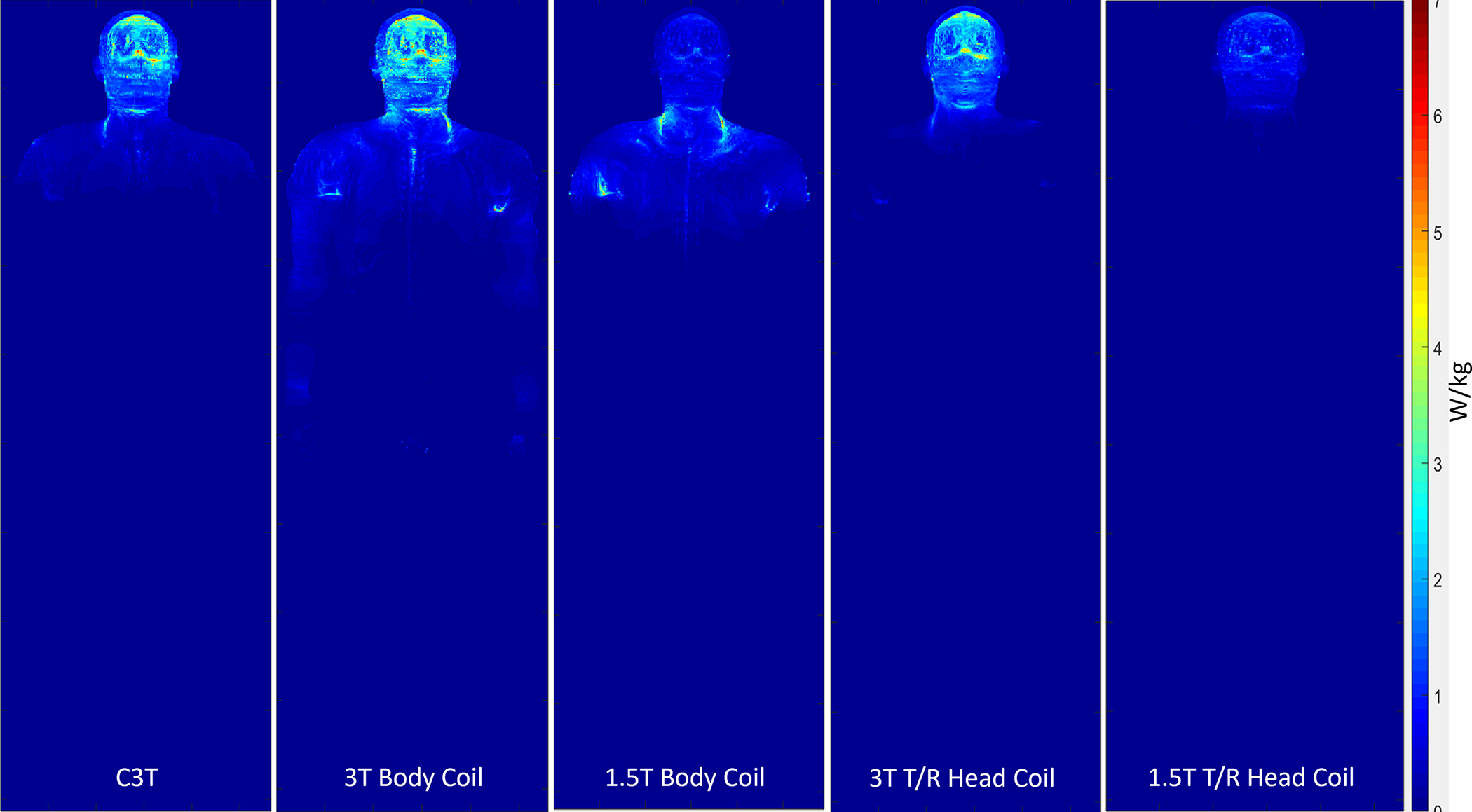
Coronal maximum intensity projection of SAR in W/kg across the 5 different coils for a B1+rms value of 1.0 μT. C3T: Compact 3T
Figure 2:
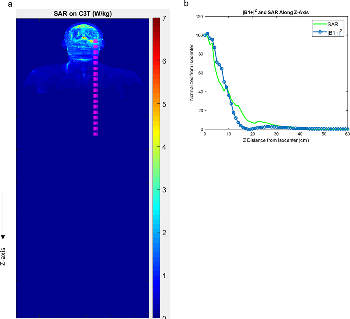
a) Coronal map of the maximum intensity projection of simulated SAR on the C3T (as in Figure 1). The pink region is used for the calculation in (b) showing normalized, measured (B1+)2 and simulated SAR along the z-direction. The rapid fall-off of both the fields indicates that RF heating is greatly reduced at the location of the implanted devices and measured (B1+)2 is a reasonable surrogate for SAR. C3T: Compact 3T
Table 2.
Average head SAR simulated for 5 different transmit RF coils, based on B1+rms of 1.0 μT.
| Coil | Average Head SAR (W/kg) | Average Whole-body SAR (W/kg) |
|---|---|---|
|
| ||
| C3T | 0.5296 | 0.0529 |
| 3T Body Coil | 0.6142 | 0.0967 |
| 3T T/R Head Coil | 0.4849 | 0.0430 |
| 1.5T Body Coil | 0.1741 | 0.0550 |
| 1.5T T/R Head Coil | 0.1908 | 0.0151 |
3.2. Safety Assessment
Representative usage of the device assessment tool is illustrated considering the example of subject #11 (Figures 2–4). This subject had an implanted Medtronic 3058 sacral nerve stimulator (Medtronic, Dublin Ireland). Specific MR conditions for this device include: main magnetic field strength of 1.5T, maximum spatial field gradient of 20 T/m or less, gradient slew rate of 200 T/m/s per axis or less, and use of a head T/R coil [35].
Figure 4:

Normalized contour plots shown as a percentage for the gradient amplitude calculated for the three gradient axes within the scanner dimensions. As explained in [21], the maximum slew rates follow the same spatial contours on each corresponding axis. The contour labeled as 20 corresponds to 20% of 700 T/m/s or 140 T/m/s, which is well below the labeled condition of 200 T/m/s. At isocenter, each maximum gradient amplitude is normalized to the maximum value at isocenter. The red circle shows the location of the implantable pulse generator (IPG). The lead tip location is not visible as the z-coordinate was greater than 80 cm away from isocenter.
As shown in Figure 3, the main magnetic field strength for both the IPG and the lead tip are within the labeled MR conditional values. While the device labeling called for a T/R head coil, the C3T brain exam was performed with a 32-channel receive head coil because its RF transmitter is much shorter and smaller than a whole-body RF body coil [18]. The spatial field gradient at the location of the IPG and lead tip which were 4.0 T/m and <0.1 T/m, respectively. Based on these results, all MR conditions for this device are met at the location of the device as shown in Figures 2–4.
Figure 3:
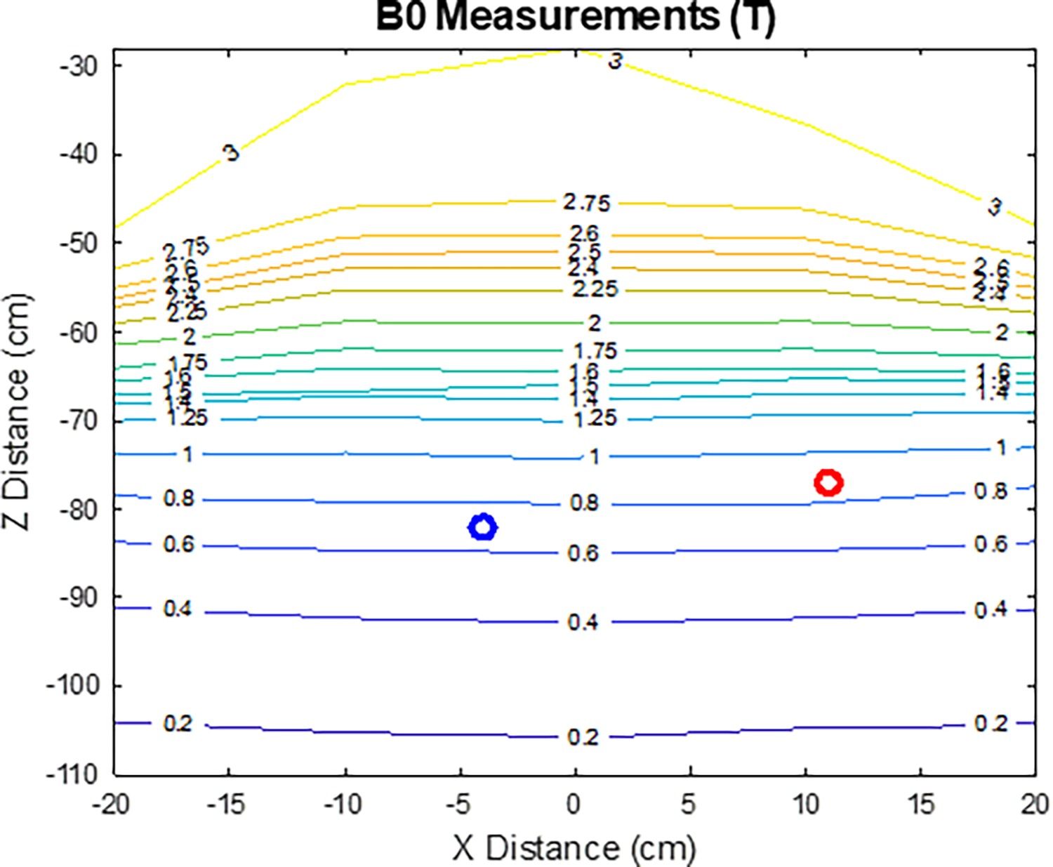
Measured main magnetic field strength for the specified location of the device implantable pulse generator (IPG) (red circle) and lead tip (blue circle).
Table 3 summarizes the results of the device assessment tool for the twelve subjects. Based on the individualized safety assessment, a board-certified MR physicist determined the C3T exam was safe to perform prior to each subject’s exam. In the case of the IPG or lead location resulting in B0 > 1.5T (Table 3), the physicist determined the excess B0 on the C3T posed no significant risk to the patient, based on knowledge of the specific device and the previously-mentioned rapid falloff of the electric field, consistent with the guidance of the IRB-approved protocol.
Table 3.
Device assessment tool results for all twelve subjects.
| Subject | Height (cm) | CT or X-ray | Component of Device | B0 (T) | Normalized B1+(%) | Normalized (B1+)2 (%) | dB/dz (T/m) |
|---|---|---|---|---|---|---|---|
|
| |||||||
| 1 | 157.5 | CT | IPG | 1.8* | <4.6 | <0.2 | 7.48 |
| Lead Tip | 1.4 | <4.6 | <0.2 | 6.14 | |||
| 2 | 158.2 | CT | IPG | 2.1* | 4.6487 | 0.216 | 7.22 |
| Lead Tip | 2.9* | 14.0965 | 1.9871 | 0 | |||
| 3 | 156.1 | CT | IPG | 1.7* | <4.6 | <0.2 | 6.86 |
| Lead Tip | 1.3 | <4.6 | <0.2 | 5.48 | |||
| 4 | 158.5 | X-ray | Lead Bottom | 2.6* | 5.6095 | 0.3147 | 5.1 |
| Lead Tip | 3* | 15.2462 | 2.3245 | 0 | |||
| 5 | 162.6 | X-ray | IPG | 1.75* | <4.6 | <0.2 | 7.22 |
| Lead Tip | 2.9* | 12.8254 | 1.6449 | 0 | |||
| 6 | 167.5 | IR X-ray | IPG | 1.25 | <4.6 | <0.2 | 5.32 |
| Lead Tip | 2.85* | 10.207 | 1.0418 | 0 | |||
| 7 | 175.4 | X-ray | Lead Bottom | 2.75* | 6.5459 | 0.4285 | 4.72 |
| Lead Tip | 3* | 15.8469 | 2.5112 | 0 | |||
| 8 | 182.9 | No CT or X-ray | IPG | - | - | - | - |
| Lead Tip | - | - | - | - | |||
| 9 | 157 | No CT or X-ray | IPG | - | - | - | - |
| Lead Tip | - | - | - | - | |||
| 10 | 184.1 | X-ray | Lead Bottom | 2.9* | 14.0965 | 1.9871 | 0 |
| Lead Tip | 3* | 16.2956 | 2.6555 | 0 | |||
| 11 | 184.6 | CT | IPG | 0.9 | <4.6 | <0.2 | 4 |
| Lead Tip | 0.7 | <4.6 | <0.2 | 0 | |||
| 12 | 151 | CT | IPG | 1.9* | 4.5688 | 0.2087 | 7.66 |
| Lead Tip | 1.55* | <4.6 | <0.2 | 6.46 | |||
Board-certified MR physicist determined the excess B0 on the C3T posed no significant risk to the patient in accordance with our IRB-approved protocol. IPG: Implantable pulse generator
3.3. Clinical and C3T Exam
Figures 5–7 show representative whole-body 1.5T versus C3T comparison images, some of which were presented in preliminary work at conferences [22,24,25]. The image comparisons are: Figure 5 (subject #1, axial T2 FSE), Figure 6 (subject #7, sagittal T1 Cube (i.e., T1-weighted 3DFSE), and Figure 7 (subject #11, 3D time of flight). Note that for all subjects, the total gradient-on time for all the comparable series for the exam was less on the C3T than on the whole-body 1.5T scanners. The average gradient-on time on the C3T was 12:51± 4:09, versus the average gradient-on time for the clinical exam was 16:19± 6:13. For 42 out of 49 sequences, the individual sequence time on the C3T was less than or equal to the sequence time on the clinical scanner. An explanation for the seven exceptions is presented in Discussion.
Figure 5:
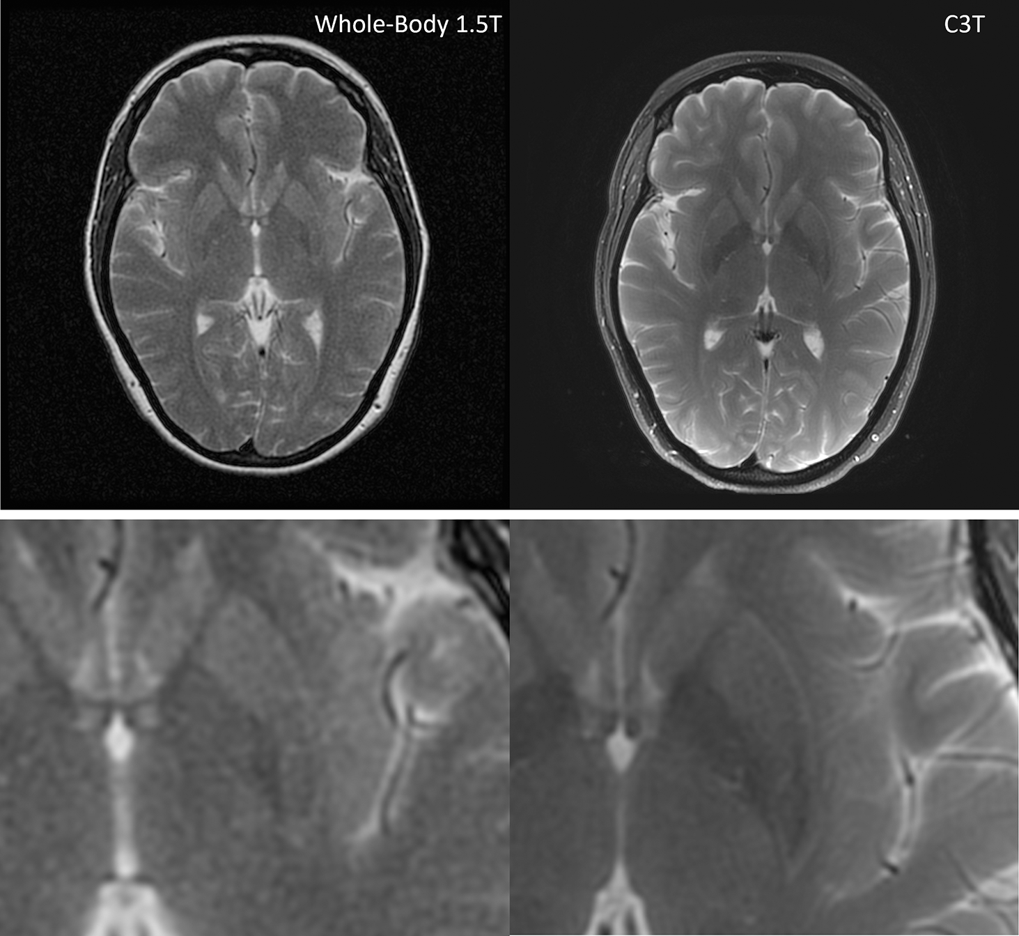
T2 FSE images for subject #1. The whole-body 1.5T image is on the left with a scan time of 3:11 and C3T image is on the right with a scan time of 2:24. There is an increase in the visual signal to noise ratio and overall image quality on the C3T image versus the 1.5T image. Bottom row: magnified images. FSE: Fast Spin Echo, C3T: Compact 3T
Figure 7:
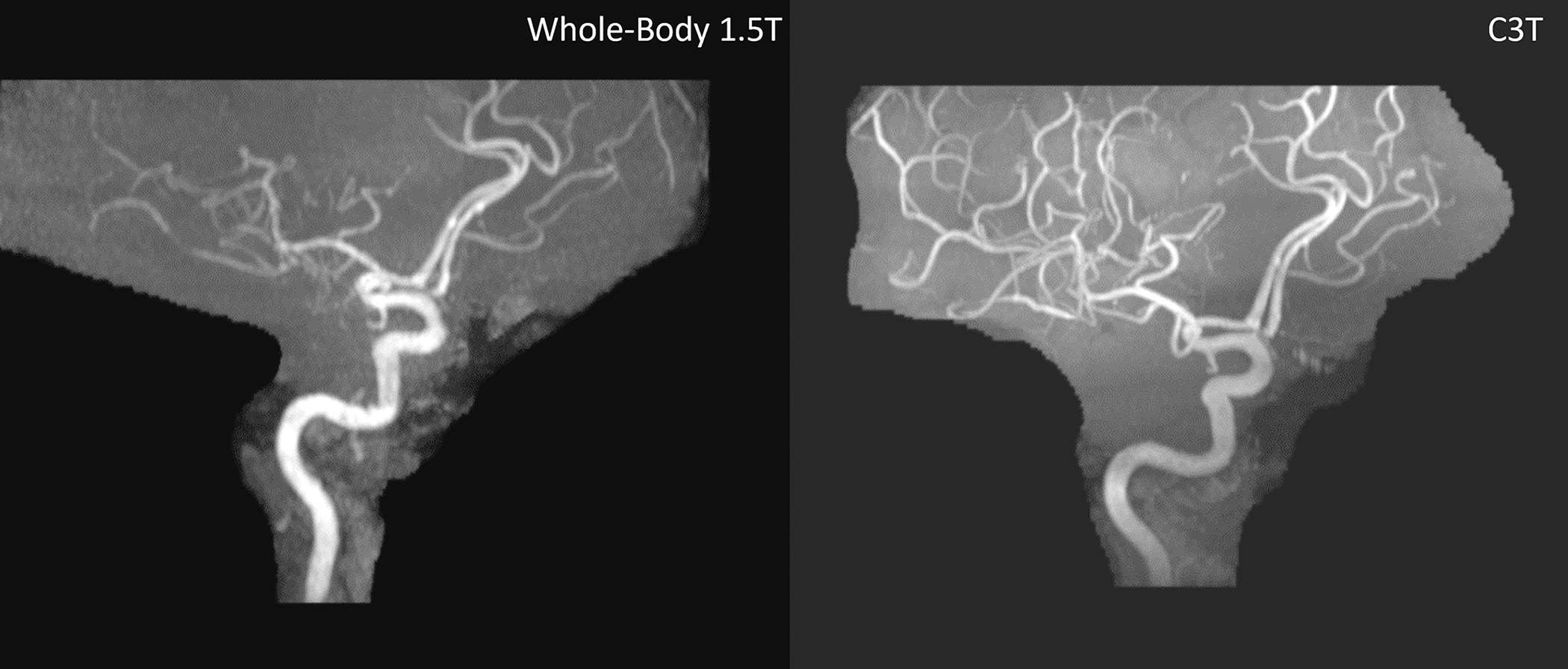
3DTOF MRA exam without contrast for subject #11 showing the right anterior circulation. The whole-body 1.5T image is shown on the left with a scan time of 7:11 and the C3T is on the right with a scan time of 5:40. This is the only case where the C3T exam was first followed by the clinical exam. The 1.5T exam is degraded by motion and apparent coil issues. TOF MRA: Time-of-flight magnetic resonance angiography FSE: Fast Spin Echo C3T: Compact 3T
Figure 6:

Sag Cube T1 images from subject #7. The whole-body 1.5T image is shown on the left with a scan time of 5:30 and the C3T is on the right with a scan time of 4:08. The scan time is decreased on the C3T. The arrows point out an enhancing meningioma. The C3T image has increased distinctness and improved signal of the associated dural tail extending inferior to the main mass. C3T: Compact 3T
3.4. Image Quality Evaluation and Statistical Analysis
The distribution of consensus image quality scoring is provided in supplemental Figure S1 which indicates the C3T images have improved image quality compared to the 1.5T images for most sequences. The improved image quality of the C3T is clearly apparent on Figures 5–7, and the blinded evaluation of all images in comparison resulted in the C3T scanner significantly (P < 0.001) outperformed the whole-body 1.5T for overall image quality.
4. DISCUSSION
At many institutions including our own, 3T has become the clinical standard for brain imaging. Due to MR safety concerns, 3T MRI is unavailable for many patients with implanted devices according to the device labeling. This may be due to the higher field strength and increased RF power deposition (as shown in Figure 1), or simply because device testing at 3T has not yet been reported or the device labeling has not been updated. Interestingly, despite the increase in SAR at 3T, under some conditions lead tip heating at 3T may be reduced compared to 1.5T, which could be attributable to differences in resonant length [36]. However, when devices are labeled as MR conditional both at 1.5T and 3T, the conditions are typically much more restrictive at 3T. For example, the labeled limit for SAR in W/kg is at least factor of 2 lower at 3T for the cochlear implants described in [37]. Another example is the Medronic sacral modulation system comprising a model 97810 IPG and 978B1 lead [6], where labeled SAR ≤ 2.0 and 1.4 W/kg at 1.5T and 3T, respectively.
We imaged patients with three types of implanted devices. The first two types, spinal and sacral nerve stimulators, comprise many models which are MR conditional consisting of an IPG and leads. The use of the C3T allows greater performance for brain exams, i.e., 3.0T field strength and 700 T/m/s slew rate at the location of the brain, while satisfying the MR conditions at the location of the device components, in accordance with our IRB-approved protocol. The third type of implanted device exam reported here is abandoned leads from CIEDs such as pacemakers and implantable cardioverter-defibrillators (ICDs), which introduce additional MR safety concerns. Abandoned leads pose a greater risk for RF related lead tip heating [2, 31, 38] compared to complete CIED systems. Therefore, subjects with abandoned leads require special attention during an MR exam, as there are currently no abandoned leads labeled as MR conditional. The Heart Rhythm Society consensus statement [3] suggests avoiding MR exams when abandoned CIED leads are present as there is currently considered to be insufficient data on the safety of scanning. Nevertheless, we do offer these patients clinical 1.5T exams at our institution, with informed consent and strict physiological monitoring, as described in section 2.2. Previous MR studies of patients with abandoned CIED leads have been reported at 1.5T [39].
This study demonstrates how subjects with implanted devices, including some commonly-implanted stimulators and abandoned CIED leads, can be safely scanned at 3T with high-performance gradients and a high-channel count receive coil. Significant improvement in image quality was observed on the C3T images; we believe this is due to improvements in SNR (due to field strength and the use of a multi-channel receive coil) and reduced distortion (due to increased gradient slew rate which reduces echo spacing [40]) on the C3T.
The device assessment tool used X-ray or CT images to provide an individualized location of the device IPG and lead tip. These individualized locations were then used to assess the SAR, main magnetic field strength, and gradient amplitude for each subject. This assessment could be further individualized by repeating the SAR calculations shown in Figures 1 and 2 for additional human body models e.g., Fats, Ella, Glenn, etc. (IT’IS Foundation, Zurich, Switzerland). In terms of validation, the main magnetic field plot shown in Figure 3 was measured, so it is not based on any model assumptions. The gradient fields shown in Figure 4 were calculated based on electromagnetic theory, and were experimentally validated because the same, calculated spatial dependence was used to calculate gradient non-linearity [41–42], which was measured with fiducial phantoms. Finally, the SAR plots shown in Figure 1 were calculated based on electromagnetic theory and a human body model, and were compared to the B1+ field values (Figure 2b), which was experimentally measured [23].
For all 12 subjects, the total acquisition time was longer for the 1.5T clinical exam than the corresponding C3T exam. In 42 out of 49 sequences (i.e., series), the acquisition time on the C3T was also less than or equal to its clinical counterpart. The seven exceptions occurred because of three main reasons. First, the acquisition time of a series was longer on the C3T whenever a single 3D series replaced two acquired planes of a 2D sequence. In these cases, the total acquisition time for the two planes on the whole-body scanner still exceed that of the C3T’s 3D exam. For example, subject #1 received a single 3D Sag T1-weighted Cube series (scan time 5:40), which replaced the Ax T1 and Cor T1 (scan times 2:49+3:11 = 6:00) on the whole-body scanner. The difference in protocol arose because the wider use of 3D acquisition, with subsequent reformatting, is more standard at 3T in our practice. A second reason is roundoff (by no more than 30 seconds) due to higher spatial resolution of the C3T exam, which again is in accordance with our clinical practice for 1.5T versus 3.0T imaging. For example, subject #2, the sequence time for the Ax T2 was 2:36 on the clinical scanner versus 2:42 on the C3T, however the frequency encoded matrix increased from 256 to 320. Analogous effects are seen for subjects #4, 8, and 11. Finally, for subject #3, the increase in sequence time for the 2D T2 FLAIR of 1:20 is a result of differences in vendor optimization of a 2D FLAIR sequence for parameters including repetition time (TR), inversion time (TI), and percent sampling. Nevertheless, the total exam time for the C3T exam for subject #3 was 16:09 versus 24:17, a substantial decrease of 33.5% compared to the 1.5T clinical exam.
The stimulators reported here are typically implanted in the abdomen or pelvis, relatively far from the head where the C3T’s EM fields are greatly reduced, so labeled conditions generally can be met at the location of the device. An area for further study is to extend this to work to stimulators implanted closer to head, such as vagus nerve stimulators and hypoglossal nerve stimulators. This will require more detailed analysis of lead tip heating [33,34] based on the electric fields induced by the C3T RF transmit coil.
Most of the benefits reported here for subjects with implanted devices are directly applicable to other compact designs like the Synaptive Evry [12] and the Compact 7T [11] because the spatial extent and falloff of the RF and gradient fields are comparable with the C3T’s. The advantages also translate to whole-body magnet systems with reduced-diameter gradient inserts, including MAGNUS [13], Connectome 2.0 [14], and Impulse [15], which are currently generating strong interest due to their high gradient amplitude enabling diffusion studies for advanced neuroscience. These systems offer analogous advantages to the compact design for the falloff of RF and gradient fields, although the main magnetic field B0 profile remains that of a standard, whole-body scanner. We note that alternative architectures, such as very low-field, portable systems including the 0.064T Hyperfine Swoop [43] could also offer considerable advantages for scanning patients with implanted devices. However, imaging at such low field strengths introduces other challenges, such as low image SNR and increased concomitant gradient fields.
High performance, reduced-diameter gradients, either within a compact system or as an insert to a whole-body magnet, not only offer improved standard clinical imaging [49], but also enable improvements for advanced imaging for patients. Reported techniques include fMRI [44], DWI and DTI tractography [45], MR elastography [46], and arterial spin labeling [47]. As high-performance gradient systems become FDA 510(k) cleared, we believe that widespread adoption of this improved approach to image patients with implanted devices will become possible.
4.1. Limitations
One limitation of the study is the clinical protocol on the whole-body scanner varied. This is because the study population was taken from actual clinical patients who had varying clinical indications. Another limitation of this study is that 11 of 12 of the C3T exams followed the clinical exam due to logistical considerations, such as the administration of a gadolinium-based contrast agent during the clinical exam. Because of the extended MRI session caused by two exams, we expect subjects had tendency to move more during the C3T exam. The radiologists noted motion artifact in seven out of twelve subjects, corresponding to 8/49 series of the C3T images during the blinded review compared to 2/49 series on the whole-body scanner. Also, higher spatial resolution exams tend to exhibit increase motion conspicuity. We do not think the increased motion resulted from a lack of patient comfort on the C3T, because direct comparisons previously indicated improved patient comfort on the C3T [48]. Note that this systematic bias towards motion artifact due to exam order favors the whole-body exam image quality, contrary to our result. On the other hand, the C3T exam benefited from increased contrast agent soak-in time for post-gad T1-weighted sequences. However, we do not believe that this was primary determinant of the results because the radiologists observed improved image quality across all sequences, including the sequences which are insensitive to contrast enhancement, such as T2-weighted FSE. Another limitation of the study is that while we made every effort to blind the study, we acknowledge that neuroradiologists can often determine 1.5T versus 3.0T field strength from image appearance. Finally, while this is a limited-scale study, the image quality results show a highly significant P value, despite the relatively small sample size.
5. Conclusion
In conclusion, we demonstrated how small-bore systems can offer a significant advantage for scanning patients with implanted devices. This was demonstrated in a small-scale study where the image quality obtained from a C3T scanner outperformed the whole-body 1.5T scanner in terms of image quality for subjects with implanted devices or abandoned CIED leads. This result is not surprising given that it was previously shown the image quality of C3T exams was superior to that from whole-body 3T scanner (using the same RF receive coil) for subjects without implanted devices [49].
The results presented here further highlight advantages of anatomy-specific, dedicated MRI scanners, compared to general-purpose systems that necessarily compromise some performance to cover all anatomical regions. Most of the results presented here are expected to be applicable to other compact MR designs, as well as to high-performance gradient inserts. This study demonstrated the feasibility and advantages of using reduced-bore MRI systems to benefit patients with implanted devices.
Supplementary Material
Table S1 Relevant scan parameters for the series for each of the 12 subjects.
Figure S1: Distribution of consensus radiologist scores of overall image quality comparing each whole-body 1.5T sequence with the corresponding compact 3T sequence.
Figure S2: |dB/dt| calculated as described in the Appendix for an extremely high-performance gradient scenario of amplitude=80 mT/m and slew rate=700 T/m/s, applied simultaneously on the C3T with a unipolar gradient lobe. Note that dB/dt does not exceed Normal Operating Mode at the location of the implanted devices considered in this study. The x- and z-gradient axes are shown for two representative values of patient height. The y-gradient axis plots are omitted because the results are more favorable than the x-gradient axis shown.
Acknowledgement:
We thank Joseph Arant, R.N. for his help monitoring the CIED abandoned lead exams.
Funding:
This work was supported in part by National Institute of Health U01EB024450.
6. Appendix
While device labeling typically accounts for dB/dt effects by imposing limits on maximal slew rate (in units of T/m/s), regulatory documents such as IEC 60601-2-33 [50] instead specify limits on dB/dt directly (in units of T/s) with a two-parameter model,
| (A1) |
where is the chronaxie, is the gradient ramp time, and is the rheobase, taken to be 20 T/s for First Level Control Mode, and 16 T/s for Normal Operating Mode.
As a supplement to Figure 4, we calculated |dB/dt| (including all three vector components) based on EM modeling of the gradient for a unipolar gradient lobe simultaneous amplitude of 80 mT/m and slew rate of 700T/m/s on the compact 3T, yielding a ramp time . The results are shown as contour lines in supplemental Figure S2, indicating that even for this extremely high-performance gradient scenario, Normal Operating mode for dB/dt is not exceeded at the location of the implanted devices considered in this study.
REFERENCES
- 1.McRobbie DW. Essentials of MRI Safety. Wiley-Blackwell; 2020. 379p [Google Scholar]
- 2.Yang E, Suzuki M, Nazarian S, Halperin HR. Magnetic resonance imaging safety in patients with cardiac implantable electronic devices. Trends Cardiovasc Med. 2022. Oct;32(7):440–447. doi: 10.1016/j.tcm.2021.08.001. [DOI] [PubMed] [Google Scholar]
- 3.Indik JH, Gimbel JR, Abe H, et al. 2017 HRS expert consensus statement on magnetic resonance imaging and radiation exposure in patients with cardiovascular implantable electronic devices. Heart Rhythm. 2017. Jul;14(7):e97–e153. doi: 10.1016/j.hrthm.2017.04.025. [DOI] [PubMed] [Google Scholar]
- 4.http://www.doctordoctor.biz/search/Search.aspx, accessed 0912/2022.
- 5.Shellock FG. Reference manual for magnetic resonance safety, implants, and devices: 2015edition. Los Angeles, CA: Biomedical Research Publishing Group; 2015. 750p [Google Scholar]
- 6. [Assessed 3/1/2023]. https://usermanual.wiki/m/0fdeb64a7289e09695643ee5e765bd7d39a169edf2df45df399fb2653bda6670.
- 7.Alvarez-Linera J. 3T MRI: Advances in brain imaging. Eur J Radiol. 2008. Sep;67(3):415–26. doi: 10.1016/j.ejrad.2008.02.045. [DOI] [PubMed] [Google Scholar]
- 8.Pruessmann KP, Weiger M, Scheidegger MB, Boesiger P. SENSE: sensitivity encoding for fast MRI. Magn Reson Med. 1999. Nov;42(5):952–62. [PubMed] [Google Scholar]
- 9.Griswold MA, Jakob PM, Heidemann RM, et al. Generalized autocalibrating partially parallel acquisitions (GRAPPA). Magn Reson Med. 2002. Jun;47(6):1202–10. doi: 10.1002/mrm.10171. [DOI] [PubMed] [Google Scholar]
- 10.https://nevro.com/English/us/providers/product-manuals/default.aspx accessed 9/23/2022.
- 11.Foo TK, Vermilyea M, Minfeng X, et al. Design and Construction on a Low-Cryogen. Lightweight, High-Performance, Head-only Compact 7T MRI. In: Proceedings of the Annual Meeting of ISMRM, Online, 2021. (abstract 0561) [Google Scholar]
- 12.Stainsby J, Bindseil G, Connell I, et al. Imaging at 0.5 T with high-performance system components. In: Proceedings of the 27th Annual Meeting of ISMRM, Montreal, 2019. (abstract 1194) [Google Scholar]
- 13.Foo TK, Tan ET, Vermilyea ME, et al. Highly efficient head-only magnetic field insert gradient coil for achieving simultaneous high gradient amplitude and slew rate at 3.0 T (MAGNUS) for brain microstructure imaging. Magn Reson Med. 2020. Jun;83(6):2356–2369. doi: 10.1002/mrm.28087. [DOI] [PubMed] [Google Scholar]
- 14.Huang SY, Witzel T, Keil B, et al. Connectome 2.0: Developing the next-generation ultra-high gradient strength human MRI scanner for bridging studies of the micro-, meso-and macro-connectome. Neuroimage. 2021. Nov;243:118530. doi: 10.1016/j.neuroimage.2021.118530. [DOI] [PMC free article] [PubMed] [Google Scholar]
- 15.Feinberg D, Dietz P, Liu C, et al. Design and Development of a Next-Generation 7T human brain scanner with high-performance gradient coil and dense RF arrays. In: Proceedings of the Annual Meeting of ISMRM, Online, 2021. (abstract 0562) [Google Scholar]
- 16.Turner R. Gradient coil design: a review of methods. Magn Reson Imaging. 1993;11(7):903–20. doi: 10.1016/0730-725x(93)90209-v. [DOI] [PubMed] [Google Scholar]
- 17.Lee SK, Bernstein MA. Systematic Dimensional Analysis of the Scaling Relationship for Gradient and Shim Coil Design Parameters. Magn Reson Med. 2022. Oct;88(4):1901–1911. doi: 10.1002/mrm.29316. [DOI] [PMC free article] [PubMed] [Google Scholar]
- 18.Foo TKF, Laskaris E, Vermilyea M, et al. Lightweight, compact, and high-performance 3T MR system for imaging the brain and extremities. Magn Reson Med. 2018. Nov;80(5):2232–2245. doi: 10.1002/mrm.27175. [DOI] [PMC free article] [PubMed] [Google Scholar]
- 19.Lee SK, Mathieu JB, Graziani D, et al. Peripheral nerve stimulation characteristics of an asymmetric head-only gradient coil compatible with a high-channel-count receiver array. Magn Reson Med. 2016. Dec;76(6):1939–1950. doi: 10.1002/mrm.26044. [DOI] [PMC free article] [PubMed] [Google Scholar]
- 20.In MH, Shu Y, Trzasko JD, et al. Reducing PNS with minimal performance penalties via simple pulse sequence modifications on a high-performance compact 3T scanner. Phys Med Biol. 2020. Jul 31;65(15):15NT02. doi: 10.1088/1361-6560/ab99e2. [DOI] [PMC free article] [PubMed] [Google Scholar]
- 21.Bernstein MA, Edmonson HA, Hua Y, et al. Compact 3T MRI for imaging patients with implanted devices: Maximum gradient slew rate considerations. In: Proceedings of the 27th Annual Meeting of ISMRM, Montreal, 2019. (abstract 4197) [Google Scholar]
- 22.Bardwell Speltz L, Shu Y, Watson R, et al. Compact 3T brain MRI for patients with abandoned leads of cardiac implantable electronic devices. In: Proceedings of the 31st Annual Meeting of ISMRM, London, 2022. (abstract 5266) [Google Scholar]
- 23.Shu Y, Meyer NK, Bardwell LJ, et al. Compact 3T MRI for imaging patients with implanted devices: RF and SAR considerations. In: Proceedings of the 27th Annual Meeting of ISMRM, Montreal, 2019. (abstract 4189) [Google Scholar]
- 24.Bardwell Speltz L, Shu Y, In MH, et al. Compact 3T MRI for patients with implanted devices: Software tool to display MR fields at a specified location. In: Proceedings of the Annual Meeting of ISMRM, Online, 2021. (abstract 4462) [Google Scholar]
- 25.Bardwell Speltz L, Shu Y, Watson R, et al. Evaluation of a compact 3T scanner for patients with MR conditional implanted devices. In: ISMRM Workshop on MR Safety: From Physics & Physiology to Policies & Practice, New York City, 2022. (abstract 4) [Google Scholar]
- 26.De Wachter S, Knowles CH, Elterman DS, et al. New Technologies and Applications in Sacral Neuromodulation: An Update. Adv Ther. 2020. Feb;37(2):637–643. doi: 10.1007/s12325-019-01205-z. [DOI] [PMC free article] [PubMed] [Google Scholar]
- 27.http://www.idph.state.il.us/about/womenshealth/factsheets/inc.htm, accessed 9/23/2022.
- 28.Jensen MP, Brownstone RM. Mechanisms of spinal cord stimulation for the treatment of pain: Still in the dark after 50 years. Eur J Pain. 2019. Apr;23(4):652–659. doi: 10.1002/ejp.1336. [DOI] [PMC free article] [PubMed] [Google Scholar]
- 29.Coulter ID, Crawford C, Hurwitz EL, et al. Manipulation and mobilization for treating chronic low back pain: a systematic review and meta-analysis. Spine J. 2018. May;18(5):866–879. doi: 10.1016/j.spinee.2018.01.013. [DOI] [PMC free article] [PubMed] [Google Scholar]
- 30.Perez AA, Woo FW, Tsang DC, Carrillo RG. Transvenous Lead Extractions: Current Approaches and Future Trends. Arrhythm Electrophysiol Rev. 2018. Aug;7(3):210–217. doi: 10.15420/aer.2018.33.2. [DOI] [PMC free article] [PubMed] [Google Scholar]
- 31.Padmanabhan D, Kella DK, Mehta R, et al. Safety of magnetic resonance imaging in patients with legacy pacemakers and defibrillators and abandoned leads. Heart Rhythm. 2018. Feb;15(2):228–233. doi: 10.1016/j.hrthm.2017.10.022. [DOI] [PubMed] [Google Scholar]
- 32.Tarasek MR, Shu Y, Kang D, et al. Average SAR prediction, validation, and evaluation for a compact MR scanner head-sized RF coil. Magn Reson Imaging. 2022. Jan;85:168–176. doi: 10.1016/j.mri.2021.10.011. [DOI] [PMC free article] [PubMed] [Google Scholar]
- 33.Nyenhuis JA, Park SM, Kamondetdacha R, Amjad A, Shellock FG, Rezai AR. MRI and implanted medical devices: basic interactions with an emphasis on heating. IEEE Transactions on Device and Materials Reliability, 2005. vol. 5, no. 3, pp. 467–480. doi: 10.1109/TDMR.2005.859033 [DOI] [Google Scholar]
- 34.Park SM, Kamondetdacha R, Nyenhuis JA. Calculation of MRI-induced heating of an implanted medical lead wire with an electric field transfer function. J Magn Reson Imaging. 2007. Nov;26(5):1278–85. doi: 10.1002/jmri.21159. [DOI] [PubMed] [Google Scholar]
- 35. [Assessed 10/10/2022]. https://mriquestions.com/uploads/3/4/5/7/34572113/interstim_contrib_214172.pdf.
- 36.Shellock FG, Begnaud J, Inman DM. Vagus nerve stimulation therapy system: in vitro evaluation of magnetic resonance imaging-related heating and function at 1.5 and 3 tesla. Neuromodulation. 2006. Jul;9(3):204–13. doi: 10.1111/j.1525-1403.2006.00061.x. [DOI] [PubMed] [Google Scholar]
- 37. [Assessed 3/1/2023]. https://mss-p-007-delivery.stylelabs.cloud/api/public/content/ee38d8aa95fd45ecb0db48a533b20c36?v=19b57305.
- 38.Langman DA, Goldberg IB, Finn JP, Ennis DB. Pacemaker lead tip heating in abandoned and pacemaker-attached leads at 1.5 Tesla MRI. J Magn Reson Imaging. 2011. Feb;33(2):426–31. doi: 10.1002/jmri.22463. [DOI] [PubMed] [Google Scholar]
- 39.Schaller RD, Brunker T, Riley MP, Marchlinski FE, Nazarian S, Litt H. Magnetic Resonance Imaging in Patients With Cardiac Implantable Electronic Devices With Abandoned Leads. JAMA Cardiol. 2021. May 1;6(5):549–556. doi: 10.1001/jamacardio.2020.7572. [DOI] [PMC free article] [PubMed] [Google Scholar]
- 40.Tan ET, Lee SK, Weavers PT, et al. High slew-rate head-only gradient for improving distortion in echo planar imaging: Preliminary experience. J Magn Reson Imaging. 2016. Sep;44(3):653–64. doi: 10.1002/jmri.25210. [DOI] [PMC free article] [PubMed] [Google Scholar]
- 41.Tao S, Trzasko JD, Gunter JL, Weavers PT, Shu Y, Huston J, Lee SK, Tan ET, Bernstein MA. Gradient nonlinearity calibration and correction for a compact, asymmetric magnetic resonance imaging gradient system. Phys Med Biol. 2017. Jan 21;62(2):N18–N31. doi: 10.1088/1361-6560/aa524f. [DOI] [PMC free article] [PubMed] [Google Scholar]
- 42.Weavers PT, Shu Y, Tao S, Huston J 3rd, Lee SK, Graziani D, Mathieu JB, Trzasko JD, Foo TK, Bernstein MA. Technical Note: Compact three-tesla magnetic resonance imager with high-performance gradients passes ACR image quality and acoustic noise tests. Med Phys. 2016. Mar;43(3):1259–64. doi: 10.1118/1.4941362. [DOI] [PMC free article] [PubMed] [Google Scholar]
- 43.Sheth KN, Mazurek MH, Yuen MM, et al. Assessment of Brain Injury Using Portable, Low-Field Magnetic Resonance Imaging at the Bedside of Critically Ill Patients. JAMA Neurol. 2020. Sep 8;78(1):41–7. doi: 10.1001/jamaneurol.2020.3263. [DOI] [PMC free article] [PubMed] [Google Scholar]
- 44.Kang D, In MH, Jo HJ, Halverson MA, Meyer NK, Ahmed Z, Gray EM, Madhavan R, Foo TK, Fernandez B, Black DF, Welker KM, Trzasko JD, Huston J 3rd, Bernstein MA, Shu Y. Improved Resting-State Functional MRI Using Multi-Echo Echo-Planar Imaging on a Compact 3T MRI Scanner with High-Performance Gradients. Sensors (Basel). 2023. Apr 27;23(9):4329. doi: 10.3390/s23094329. [DOI] [PMC free article] [PubMed] [Google Scholar]
- 45.In MH, Tan ET, Trzasko JD, Shu Y, Kang D, Yarach U, Tao S, Gray EM, Huston J 3rd, Bernstein MA. Distortion-free imaging: A double encoding method (DIADEM) combined with multiband imaging for rapid distortion-free high-resolution diffusion imaging on a compact 3T with high-performance gradients. J Magn Reson Imaging. 2020. Jan;51(1):296–310. doi: 10.1002/jmri.26792. [DOI] [PMC free article] [PubMed] [Google Scholar]
- 46.Sui Y, Murphy M, Yin Z, et al. Improved brain MRE performance on a compact, lightweight 3T scanner with high-performance gradients. In: Proceedings of the 32st Annual Meeting of ISMRM, Toronto, 2023. (abstract 5401) [Google Scholar]
- 47.Kang D, Yarach U, In MH, Gray EM, Trzasko JD, Jo HJ, Shu Y, Huston J 3rd, Bernstein MA. The effect of spiral trajectory correction on pseudo-continuous arterial spin labeling with high-performance gradients on a compact 3T scanner. Magn Reson Med. 2020. Jul;84(1):192–205. doi: 10.1002/mrm.28110. [DOI] [PMC free article] [PubMed] [Google Scholar]
- 48.Gray E, Huston J III, Shu Y, et al. Patient Acceptance on a Compact 3T is Generally Superior to a Whole-Body Scanner. In: Proceedings of the Annual Meeting of ISMRM, London, 2018. (abstract 2636) [Google Scholar]
- 49.Camerucci E, Campeau NG, Trzasko JD, et al. Improved Brain MR Imaging from a Compact, Lightweight 3T Scanner with High-Performance Gradients. J Magn Reson Imaging. 2022. Jan;55(1):166–175. doi: 10.1002/jmri.27812. [DOI] [PMC free article] [PubMed] [Google Scholar]
- 50.International Electrotechnical Commission (IEC), 2015. 60601–2-33 Medical Electrical Equipment - Part 2–33: Particular requirements for the basic safety and essential performance of magnetic resonance equipment for medical diagnosis, Edition 3.2. ISBN 978–2-8322–2743–5.
Associated Data
This section collects any data citations, data availability statements, or supplementary materials included in this article.
Supplementary Materials
Table S1 Relevant scan parameters for the series for each of the 12 subjects.
Figure S1: Distribution of consensus radiologist scores of overall image quality comparing each whole-body 1.5T sequence with the corresponding compact 3T sequence.
Figure S2: |dB/dt| calculated as described in the Appendix for an extremely high-performance gradient scenario of amplitude=80 mT/m and slew rate=700 T/m/s, applied simultaneously on the C3T with a unipolar gradient lobe. Note that dB/dt does not exceed Normal Operating Mode at the location of the implanted devices considered in this study. The x- and z-gradient axes are shown for two representative values of patient height. The y-gradient axis plots are omitted because the results are more favorable than the x-gradient axis shown.