Abstract
Advances in information technology are hindered by energy dissipation from Joule losses associated with charge transport. In contrast, the process of information based on spin waves propagation (magnons) in magnetic materials is dissipationless. Low damping of spin wave excitations is essential to control the propagation length of magnons. Ferrimagnetic Y3Fe5O12 garnets (YIG) exhibit the lowest magnetic damping constants. However, to attain the lowest damping constant, epitaxial growth of YIG on single crystal substrates of Gd3Ga5O12 at elevated temperatures is required, which hinders their CMOS integration in electronic devices. Furthermore, their low saturation magnetization and magnetocrystalline anisotropy are challenging for nanoscale device applications. In the search for alternative material systems, polycrystalline ferromagnetic Co25Fe75 alloy films and ferrimagnetic spinel ferrites, such as MgAl0.5Fe1.5O4 (MAFO), have emerged as potential candidates. Their damping constants are comparable, although they are at least one order of magnitude higher than YIG’s. However, Co25Fe75 alloy thin film growth is CMOS compatible, and its magnon diffusion length is 20× longer than in MAFO. In addition, MAFO requires epitaxial growth on lattice-matched MgAl2O4 substrates. We discuss the material properties that control the Gilbert damping constant in CoxFe1−x alloys and MAFO and conclude that CoxFe1−x alloy thin films bring us closer to the realization of the exploitation of spin waves for magnonics.
Keywords: magnons, CoFe alloy thin films, MgAlFeO spinel ferrites, Gilbert damping
1. Introduction
Current computing devices rely on electron transport across transmission lines and electronic devices to perform computational tasks. The flow of electrons across resistive connections results in ohmic energy losses and heat generation, thus requiring more energy to make up for efficiency losses and the need for device cooling.
Magnonics deals with the excitation, propagation, control, and detection of spin waves through a magnetic material. It is a promising field, as ohmic losses are absent. Analogous to electrons, magnons can be used as the carriers of information and their transmission without the inherent Joule losses associated with electron transport. Magnons propagate as spin waves in the material and can be launched in ferromagnets, ferrimagnets, and antiferromagnets. For comprehensive reviews on spin wave physics and devices, the reader is referred to references [1,2,3,4].
The discovery by Bertaut and Forrat [5] that yttrium iron garnet Y3Fe5O12 (YIG) exhibits ultralow magnetic damping parameters [5,6], α, of the order of <10−4 was seminal in launching the current interest in magnonics [7]. Ferromagnetic resonance (FMR) linewidth is used to measure damping parameters, and YIG exhibits the narrowest FMR linewidths and the longest spin wave propagation length [8]. With 80 atoms per unit cell, YIG is a complex crystal [8]; the attainment of the lowest damping requires epitaxial growth on single crystal substrates of gallium gadolinium garnet (GGG) using liquid phase epitaxy [9]. YIG and GGG have unit cell dimensions of 1.2376 nm and 1.2383 nm, respectively. The lattice match enables the epitaxial growth of YIG free of structural defects and strain [10]. However, deposition/annealing temperatures in the 700–850 °C range are required [11], which can promote interfacial diffusion and the formation of structural defects [12,13]. Defects impact YIG’s magnetic anisotropy, its crystal structure, and stoichiometry.
This mini review focuses on recent progress on alternative materials to YIG garnets: CoxFe1−x alloys and MgAl0.5Fe1.5O4. A brief description of spin wave dynamics using the Landau–Liftshitz–Gilbert (LLG) equation is first given. This is followed by a discussion of the material properties and mechanisms that limit the magnetic damping in these materials. The review includes an assessment of the merits of both material types for practical devices.
2. Magnetization Dynamics and the Gilbert Damping Constant
The dynamic response of the magnetization in a material in response to an applied magnetic field is described by the Landau–Lifshitz–Gilbert (LLG) equation [14,15], which describes the time-dependent behavior of the magnetization in response to torque forces on the magnetization.
| (1) |
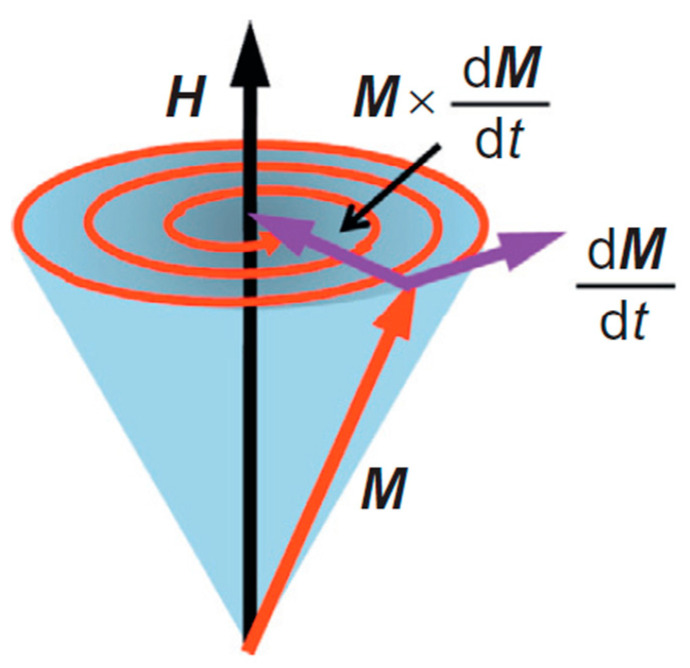
The first term represents the precession of the magnetization around the effective field Heff; this includes the applied and demagnetization fields and the anisotropy field of the material. γ is the gyromagnetic ratio, denotes the material’s magnetization vector, and is the total effective field that acts on the magnetization. The second term represents the precessional damping, with α being a unitless constant known as the Gilbert damping constant [14]. M, in the denominator of the damping term, is the magnitude of the saturation magnetization as a function of time. Without damping, the magnetization of the material precesses indefinitely around the vector orientation of Heff, due to the damping term, it spirals around Heff, and it eventually aligns itself with Heff. A representation of the magnetization precessional motion is depicted in Figure 1. If the damping term is large, a long time is required for the magnetization to align with Heff. Hence, a small α value is desired for faster response times to external stimuli [16] (p. 435).
Figure 1.
A depiction of the magnetization dynamics in response to an external magnetic field [17]. In this figure, the magnetization precesses around the applied field direction and relaxes due to the influence of magnetic damping. Reprinted with permission from Ref. [17]. Copyright 2014. Elsevier (Amsterdam, The Netherlands).
The Gilbert damping constant is a material’s limiting factor for magnon propagation. The equation also indicates that a larger saturation magnetization (the projection of M, i.e., cosθ times magnitude of M) can counterbalance, within limits, the effect of the damping constant. In fact, experimentally, it is found that despite the fact that MAFO and Co25Fe75 have comparable Gilbert damping constants, Co25Fe75 alloy thin films exhibit larger magnon propagation lengths (~20 µm) [18] than MgAl0.5Fe1.5O4 (~0.8 µm) [19]. This is largely attributed to the larger saturation magnetization moment of Co25Fe75 of 2.4 T [20], in contrast to 0.1256 T [21] for MgAl0.5Fe1.5O4.
The Gilbert damping parameter is derived from Ferromagnetic resonance (FMR) measurements [22]. Figure 2a provides a schematic representation of the FMR setup.
Figure 2.
(a) Schematic of an experimental setup employed for measurements of the Gilbert damping parameter; the key components of an FMR apparatus are identified. (b) Shows a representative spectrum of the derivative of transmitted RF power (dP/dHDC) vs. swept magnetic field (HDC). (c) Linewidth vs. RF frequency from 2 to 40 GHz [22]. Note the excellent fit with the experimental data. Reprinted with permission from Ref. [22]. Copyright 2023. Quantum Design Inc. (San Diego, CA, USA).
In the FMR measurement instrumentation, the coplanar waveguide (CPW) provides radio frequency (RF) microwave signals to the sample over a broad range of frequencies (2–40 GHz). The microwaves generate magnetic fields at RF frequencies (HRF), which can resonantly excite the magnetic samples at specific magnetic fields (HDC) and frequencies, which depend on the material properties. The magnetic thin films are placed film side down on the CPW, as the RF magnetic fields do not extend far from the interface between the thin film and the CPW. Therefore, this maximizes coupling and signal output. Furthermore, the sample should not short out the CPW. To this effect, the sample is often coated with an insulating layer, or the CPWs can also be insulated with a single layer of transparent tape. As shown in Figure 2a, HRF should be perpendicular to HDC in order to provide the most efficient excitation mechanism. To eliminate the frequency-dependent background response that may mask the relatively weak FMR response of the sample, measurements are typically performed at a fixed frequency while sweeping HDC. The sample magnetization undergoes a resonant response as HDC is swept through the resonance condition, absorbing CPW energy. By sweeping through the resonance field, RF energy is reduced, which is converted to DC voltage by a broadband RF diode.
Lock-in detection is used to improve the signal-to-noise ratio (SNR), which involves modulating the signal at a known frequency. An additional set of Helmholtz coils powered by an AC source produces a small (~1 Oe) modulation (HAC) to the much larger HDC. In this scheme, the derivative of transmitted power (dP/dHDC) is actually measured, as schematically illustrated in Figure 2b. We refer the reader to reference [22] to learn how linewidth ΔH is obtained for a particular frequency.
When the ΔH data are plotted vs. the RF frequencies (GHz), a plot of ΔH vs. f, as shown in Figure 2c, is obtained. The equation in the inset of Figure 2c is employed to extract the Gilbert damping parameter α. The higher the slope of ΔH vs. f, the higher the value of the total damping constant, α.
3. Ferromagnetic Co1−xFex Alloy Thin Films
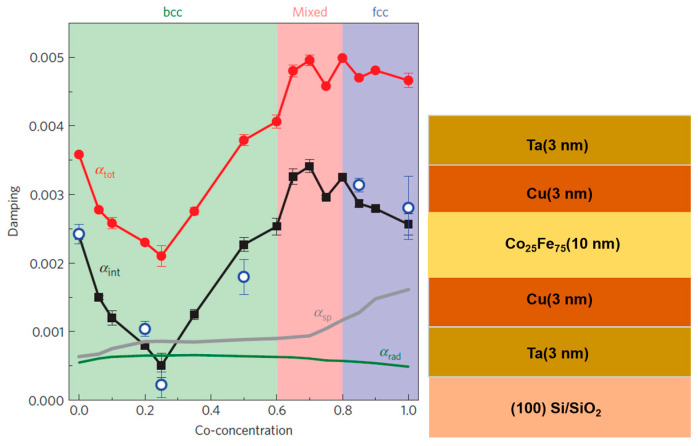
Metallic ferromagnetic films for magnonics have neglected, as it is assumed that they are unlikely to exhibit low magnetic damping due to magnon–electron scattering by the conduction electrons. Schoen et al. [20] reported on the composition dependence of the Gilbert damping constant of polycrystalline 10 nm thick Co1−xFex thin films grown at room temperature by sputter deposition onto Cu(3 nm)/Ta(3 nm) seed layers. The thin films were also capped with Cu(3 nm)/Ta(3 nm) bilayers. Their results are reproduced in Figure 3, indicating that the alloy with 25 at. % Co exhibits the lowest damping parameter.
Figure 3.
Plot of Gilbert damping parameter vs. Co composition in Co1−xFex thin films [20]. Note that at 25% Co composition, there is a sharp decrease in the damping parameter (both intrinsic and total). On the right side of the Figure, the thin film stack employed is illustrated. Reprinted with permission from Ref. [20]. Copyright 2016. Springer Nature (Berlin, Germany).
The measured values of the total damping constant for 10 nm thin films are αtotal = (2.1 ± 0.1) × 10−3 at a Co-concentration of 25%. As discussed by the authors, extrinsic contributions increment the value of the intrinsic damping constant, αint. Two significant effects are radiative damping and spin pumping. Radiative damping arises from inductive coupling of the precessing magnetization and the coplanar waveguide employed in the FMR measurement. The damping contribution due to spin pumping involves spin polarized electron injection from CoFe into the Cu/Ta seed and capping layers. Figure 3 provides intrinsic damping constant values after correction for extrinsic contributions. An ultralow value of αint = (5 ± 1.8) × 10−4 at a Co-concentration of 25% is reported. The strong composition dependence of the Gilbert damping constant in Co1−xFex alloys is ascribed by Schoen et al. to changes in the electron density of states (DOS) at the Fermi level as a function of composition. Their electronic structure calculations, together with the values of αint, are shown in Figure 4 and clearly indicate that the damping is smallest at the DOS minimum for Co = 25%. For full details and explanation of this Figure, the reader is referred to reference [20].
Figure 4.
(a) Correlation of the minimum damping at 25% Co composition and the electronic density of states (DOS). Bulk electronic structure obtained for various Co1−xFex alloys are shown in different colors. Note that the dashed vertical line at 0 is EF to ease the comparison. (b) Plot of intrinsic damping of Co1−xFex (different Co compositions) compared with theoretical calculations by Mankovsky et al. [23]. Note the deep minimum in the density of states at Fermi energy n(EF) [20]. Reprinted with permission from Ref. [20]. Copyright 2016. Springer Nature.
Experiments by Fackle et al. [18] on sputter deposited thin films of Co25Fe75 alloy confirmed the ultralow values of its intrinsic damping parameter (αint = (3.18 ± 0.48) × 10−4). They employed an out-of-plane (hard axis) FMR measurement geometry to suppress two-magnon scattering contributions to the damping parameter [24]. The intrinsic damping constant is impacted by radiative, spin pumping, and spin-flip processes, resulting in values that exceed the intrinsic value by 4.2×.
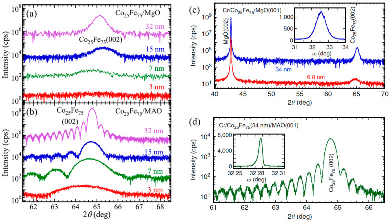
The intrinsic damping constant in Co25Fe75 alloys is also controlled by the thin film microstructure; the role of epitaxial growth has been investigated by Cheng et al. [25], and the influence of the seed/buffer layers has been investigated by Edwards et al. [26]. A comparison of thin film growth quality on MgO and MAO substrates is presented in Figure 5. The lattice parameters of the Co25Fe75 film and the MAO substrates have a lattice mismatch of 0.4% compared to 3.9% with MgO [25,27]. Thus, epitaxial growth of Co25Fe75 films on MAO substrates is achieved as opposed to strained epitaxial growth of Co25Fe75 growth on MgO substrates. Figure 5a shows XRD spectra for films of Co25Fe75 of various thicknesses grown directly on (001) MgO substrates with 2.8 nm Cr capping layers. Similarly, Figure 5b presents XRD spectra for films of Co25Fe75 of different thicknesses grown on (001) MAO substrate with the same capping layers. The films grown on MAO exhibit superior crystalline quality compared to those grown on MgO. This is confirmed by the observation of Laue oscillations on Co25Fe75 films grown on MAO with a thickness ≥ 7 nm [25,27].
Figure 5.
XRD spectra of Co25Fe75 thin films with varying thicknesses grown on (a,c) MgO and (b,d) MgAl2O4 (MAO) [25,27]. Note the Laue oscillations for films grown on MAO, which are indicative of high-quality crystalline growth. Insets in (c,d) are XRD rocking curve measurements; the lower full width at half maxima (FWHM) is indicative of less mosaic spread and a better degree of epitaxy in the case of films grown on MAO. Figure 5a,b reprinted with permission from Ref. [25]. Copyright 2018. AIP Publishing (College Park, MD, USA).
Similar structural results were observed by Lee et al. [27] Figure 5c presents XRD measurements for Co25Fe75 films (6.8 nm and 34 nm) grown directly on MgO with 2.8 nm Cr capping layers, whereas corresponding measurements for 34 nm Co25Fe75 thin films grown on MAO are shown in Figure 5d [27]. Laue oscillations are also observed for growth on MAO substrate, which are indicative of the excellent crystal quality of the thin film. The rocking curve measurements (see insets in (c,d)) exhibited FWHM values of 0.680 for films grown on MgO compared to 0.00570 for films grown on MAO.
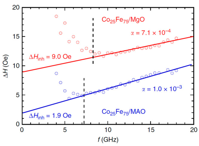
Figure 6 provides FMR linewidth measurements vs. frequency for samples grown on MgO and MAO [27]. The total damping for Cr(2.8 nm)/Co25Fe75(6.8 nm)/MgO was calculated as 0.71 × 10⁻³, and that for Cr(2.8 nm)/Co25Fe75(6.8 nm)/MAO was 1 × 10⁻³. These results are somewhat surprising, as Co25Fe75 films grown on MAO exhibit superior crystalline growth quality than those grown on MgO. One would expect a higher degree of crystalline disorder (grain boundaries) to negatively contribute to the damping parameter, yet the opposite is observed here. Other thin film properties not reported in this study, such as film roughness, could contribute to the differences reported. Further thin film structural characterization is required to explain these interesting results.
Figure 6.
Ferromagnetic resonance linewidths (Oe) vs. frequency (GHz) of Cr (2.8)/Co25Fe75(6.8)/MgO(001) in red and Cr(2.8)/Co25Fe75(6.8)/MgAl2O4(001) in blue. Solid lines represent linear fit for data points represented by circles. Dashed lines represent frequencies below which inhomogeneous broadening takes place due to incomplete saturation of the films [27]. Numbers in brackets are thicknesses in nm. Note that lower slope ΔH/f indicates lower damping.
4. Role of Interfaces on the Damping Constant in Co25Fe75 Thin Films
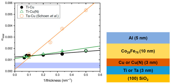
Spin pumping impacts damping, and it depends on the nature of the non-magnetic layers in contact with the Co25Fe75 thin films. Edwards et al. [26] studied the effect of 3 nm seed (Ti, Ta)/3 nm buffer (Cu, Cu(N)) bilayers on damping of Co25Fe75 thin films of different thicknesses. Figure 7 presents the measured total damping measurements. The film stacks employed in their work are also given. It was found that when Co25Fe75 thin films were grown on Ti seed layers, the spin pumping contribution was minimized, as Ti is not a good absorber of spin currents.
Figure 7.
Total damping measurements (using out-of-plane FMR geometry) in Co25Fe75 films of different thicknesses deposited on various combinations of 3 nm seed/3 nm buffer layers [26]. The blue region indicates the intrinsic damping measurements from reference [20]. On the right-hand side of the Figure, the thin film stack used is depicted. Ti-Cu(N) means that the stack consists of a 3 nm Ti seed layer and a 3 nm Cu (Nitrogen doped) buffer layer. All samples were capped with 5 nm of Al. Reprinted with permission from Ref. [26]. Copyright 2019. American Physical Society (College Park, MD, USA).
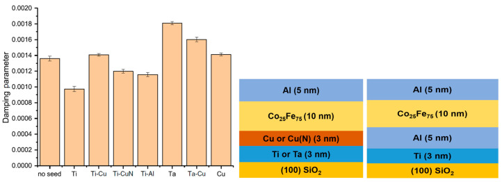
Figure 8 shows the effect of the nature of the buffer layer on the damping constant of 10 nm thick Co25Fe75 thin films. The 3 nm thick Cu, Cu(N) buffer layers were grown on 3 nm Ti and Ta seed layers, as well as on 5 nm Al buffer layers on 3 nm Ti seed layers. All samples were capped with 5 nm Al layers. The various combinations are schematically illustrated in the figure.
Figure 8.
The total damping constant of 10 nm thick Co25Fe75 thin film grown on different seed/buffer layer combinations. All seed layers are 3 nm thick, except for Al (5 nm) [26]. Notation: Ti, Cu (Ti, Cu seed layer, no buffer layer); Ti-Cu, Ti-CuN, Ti-Al, Ta-Cu (Ti or Ta seed layer, Cu, CuN, Al buffer layer). Reprinted with permission from Ref. [26]. Copyright 2019. American Physical Society.
The structure with a Ti seed layer without a buffer layer exhibited the lowest total damping constant, and Ti-X bilayers exhibited lower damping than Ta-X. This is indicative that spin pumping contributions are effectively suppressed by utilizing Ti seed layers [26].
5. Role of Interlayer Thickness on the Damping Constant in Co25Fe75 Thin Films
The thickness of the seed/buffer layers (interlayers) influences the thin film roughness. The effect of roughness on the magnetic damping parameter was studied by Edwards et al. [26] in Ti(3 nm)/Cu(x)/Co25Fe75(2 nm)/Al(5 nm) stacks by varying the Cu buffer layer thickness. Film roughness introduces magnetic inhomogeneities that negatively impact the damping constant [28,29]. Figure 9a shows that as the thickness of the Cu layer increases, the RMS roughness of the film stack significantly increases. Figure 9b provides the linewidth vs. frequency measurements for these films, whose slopes are used to calculate the total damping constant for the stacks. In Figure 9c, the dependence of the total damping parameter on Cu buffer layer thickness is provided, and it exhibits a clear trend: as the Cu buffer layer thickness increases, the thin film stack RMS roughness increases, which, in turn, reduces the total damping. This result is also surprising, as interlayer roughness is expected to negatively impact magnon propagation. Further structural studies are needed to understand these somewhat puzzling results.
Figure 9.
(a) Variation of thin film roughness (AFM measurements) vs. Cu buffer layer thickness. (b) FMR linewidth vs. Cu buffer thickness from 2 to 15 nm. Note that a smaller slope is indicative of lower total damping. (c) Damping parameter variation with Cu thickness [26]. Reprinted with permission from Ref. [26]. Copyright 2019. American Physical Society.
6. MgAl2−xFexO4 Spinel Ferrites
MgAl2−xFexO4 (MAFO), where x < 2, is a ferrimagnetic material in which Fe occurs in Fe2+ and Fe3+ states and is responsible for the overall magnetization of the material. There are 56 atoms per unit cell in MAFO, of which O2− anion coordinated tetrahedral sites are occupied by Mg2+ and half of the Fe3+ cations, whereas O2− anion coordinated octahedral sites are occupied by Al3+, Fe2+, and half of the Fe3+ cations [11]. Thin films of MAFO can be epitaxially grown by pulsed laser deposition (PLD) on single crystal spinel MgAl2O4 (MAO) substrates as their lattice mismatch is small (2%) [11]. The MgAl0.5Fe1.5O4 spinel ferrite exhibits an ultralow damping parameter of the order of 1.5 × 10⁻³, which is also associated with a minimum density of states that arises due to suppression of intraband electronic transitions. The low density of states at the Fermi level implies fewer conduction electrons, i.e., low damping.
7. The Role of Lattice Matching on Damping in MAFO
The close lattice match between MAFO and MAO is critical to attain low magnetic damping as it eliminates the formation of structural defects. Structural defects, such as dislocations, and the presence of antiphase boundaries increase magnetic damping [30,31,32]. Defects also lead to inhomogeneous contributions to damping by creating localized nonuniform magnetization [33]. Thin MAFO films with uniform magnetic properties grown on lattice-matched substrates are required to minimize damping contributions from structural defects.
In the case of MAFO, the importance of coherent strain over partial strain relaxation has been shown to result in low damping [11]. Recent studies of the growth of MgAl0.5Fe1.5O4 films on single crystal MgAl2O4 substrates to obtain coherent strain report damping parameters of α ~ 0.001–0.002 [21,34,35,36].
8. The Role of Film Thickness on Damping in MAFO
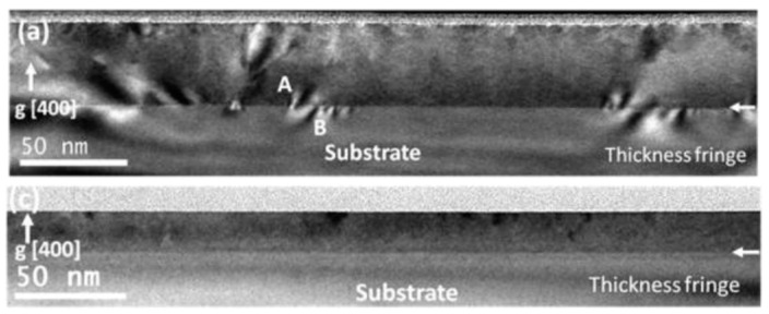
Emori et al. [21] used pulsed laser deposition (PLD) to grow MgAl0.5Fe1.5O4 thin films on MgAl2O4 substrate to study the thickness dependence of the damping parameter. The bright-field TEM images of Figure 10 show that the thicker 40 nm films exhibit many defects arising primarily from strain relaxation. Such defects are absent in the 18 nm films.
Figure 10.
Bright-field TEM images of MgAl0.5Fe1.5O4; (a) 40 nm and (c) 18 nm (the horizontal white arrow shows the film–substrate interface) [21]. Note the higher number of defects present in the thicker film (regions A and B in (a)), which are ascribed to partial stress relaxation of the film. The thinner film remains coherently strained. Reprinted with permission from Ref. [21]. Copyright 2018. American Chemical Society (Washington, DC, USA).
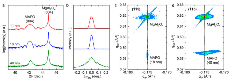
XRD, rocking curve measurements, and reciprocal space maps validate the role of film thickness on crystalline quality. The XRD results reproduced in Figure 11a indicate that MAFO films with thicknesses < 20 nm exhibit a higher degree of crystallinity, as evidenced by the presence of Laue oscillations that arise from the smooth texture of the film [21,37]. The rocking curve measurements from Figure 11b corroborate these findings. The full width at half maximum (FWHM) of the (004) peak for MAFO films < 20 nm thick is ~0.045–0.06° as compared to ~0.2° for 40 nm thick films [21]. Also, no Laue oscillations are observable in the 40 nm thick films, indicative of a poorer degree of crystallinity.
Figure 11.
Structural characterization of MgAl0.5Fe1.5O4 film with different thicknesses grown on MgAl2O4 substrate: (a) Combined 2θ XRD plots for films with varying thicknesses. (b) Rocking curves for the same films. (c,d) Reciprocal space maps for films of thicknesses of 18 nm and 40 nm, respectively [21]. Reprinted with permission from Ref. [21]. Copyright 2018. American Chemical Society.
Additional structural differences between MAFO films with varying thicknesses are provided by reciprocal space maps given in Figure 11c,d [21]. For the 18 nm thick MAFO films, there is virtually no mosaic spread. On the other hand, the 40 nm thick films exhibit a large mosaic spread; this is consistent with the TEM images (i.e., the 18 nm films are coherently strained to the substrate, whereas the 40 nm films are partially relaxed due to the presence of defects near the substrate interface).
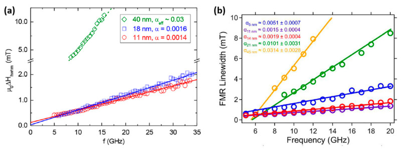
FMR measurements were utilized to correlate the structural properties of MAFO films with different thicknesses to magnetic damping parameters. In Figure 12a, α for the 11 nm and 40 nm thick films are 0.0014 and ~0.03, respectively. Similar results are shown in Figure 12b; note, however, that damping significantly increases in the 5 nm thick films. This increase in damping is attributed to the presence of a ~1 nm thick magnetic dead layer at the interface of the MAFO film and substrate. Such a layer is the region of chemical disorder that is iron deficient and that negatively affects the magnetic properties of 5 nm MAFO films. These results indicate that damping is directly correlated to the microstructural properties of MAFO films, which are influenced by the thickness of the magnetic film.
Figure 12.
FMR linewidth vs. frequency. (a) MgAl0.5Fe1.5O4 films with thicknesses of 11 nm, 18 nm, and 40 nm, respectively [21]; (b) MgAl0.5Fe1.5O4 films with thicknesses of 5 nm, 11 nm, 14 nm, 21 nm, and 45 nm, respectively [38]. Figure 12a reprinted with permission from Ref. [21]. Copyright 2018. American Chemical Society. Figure 12b reprinted with permission from Ref. [38]. Copyright 2019. AIP Publishing.
9. The Role of Fe Content in MAFO on Magnetic Damping Constant
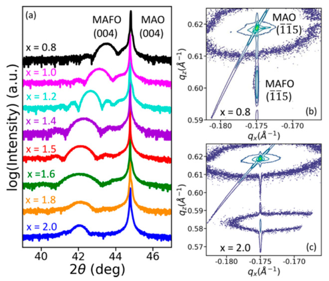
The Fe content in MgAl2−xFexO4 influences the magnetic damping properties. In Figure 13a, Laue oscillations around (004) are clearly seen in the XRD spectra for films with x < 1.6, indicating good crystallinity [36]. However, no Laue oscillations are present in films with higher Fe content (i.e., x > 1.5), which is indicative of poorer crystalline quality.
Figure 13.
Structural characterization of 11 nm thick MgAl2−xFexO4 films with varying Fe content (x = 0.8 to x = 2). (a) Combined XRD plots of different films with different Fe content, (b,c) Reciprocal space maps for MgAl1.2Fe0.8O4 and MgFe2O4 respectively [36]. Reprinted with permission from Ref. [36]. Copyright 2020. AIP Publishing.
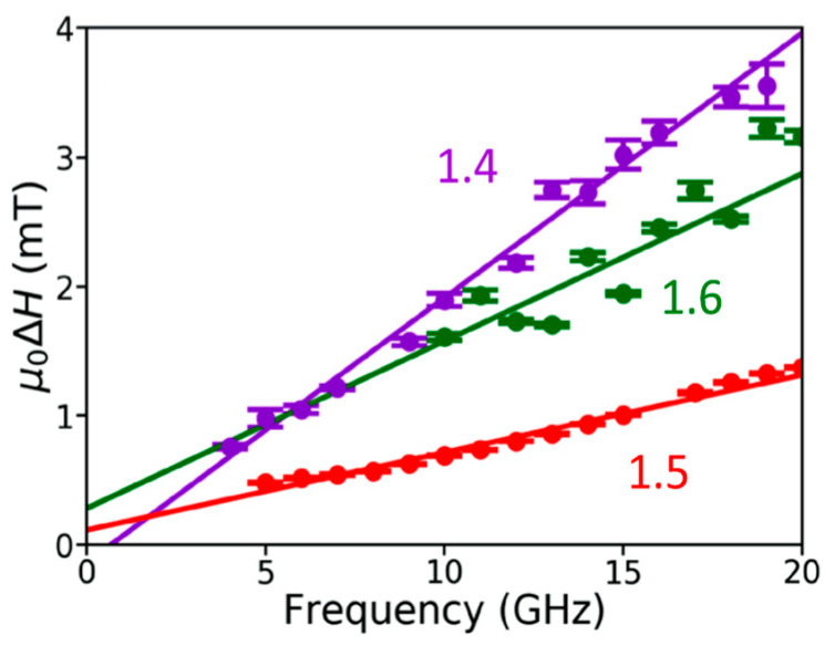
The reciprocal space maps of Figure 13b,c indicate excellent lattice matching and low mosaic spread for MgAl1.2Fe0.8O4 as opposed to poor lattice matching and large mosaic spread for MgFe2O4. Films with x < 1.4 have Curie temperatures (TC) below room temperature and, hence, were neglected in this study [36]. When the Fe content x > 1.6, the coercivity increases, possibly due to incoherent film growth. Films with 1.4 ≤ x ≤ 1.6 show soft magnetism or ferrimagnetism [36]. As seen in Figure 14, MgAl0.5Fe1.5O4 shows the narrowest FMR linewidth and the lowest damping constant (1.8 ± 0.01) × 10−3 [36]. For higher iron content (x > 1.6), the film quality degrades and the coercivity increments. This is attributed to magnetic frustration and defect pinning. Thus, the ideal iron content range was concluded to be 1.4 ≤ x ≤ 1.6 [36].
Figure 14.
FMR linewidth, dH, vs. frequency for MgAl2−xFexO4 films with varying iron content: MgAl0.6Fe1.4O4, MgAl0.5Fe1.5O4, and MgAl0.4Fe1.6O4 [36]. Reprinted with permission from Ref. [36]. Copyright 2020. AIP Publishing.
10. Discussion
The material parameters that affect the Gilbert damping parameter in ferromagnetic Co25Fe75 thin films and ferrimagnetic MgAl0.5Fe1.5O4 have been discussed in this review. Neither system attains the ultralow magnetic damping of YIG garnets. However, for VLSI devices, magnon propagation lengths in the sub to tens of micron regime are of interest.
Table 1 compares key parameters for magnonics (Gilbert damping constant and magnon propagation distance) as well as fabrication challenges for YIG, Co25Fe75, and MgAl0.5Fe1.5O4. YIG exhibits ultra-low magnetic damping constants of ~10−5, resulting in magnon propagation lengths of the order of centimeters. While highly desirable for magnonics, YIG growth requires liquid phase epitaxy and high temperatures (~1000 °C) and single crystal GGG substrates, which makes YIG garnets presently unsuitable for CMOS integration. Thus, the major challenges that YIG garnets need to overcome are to identify alternate growth techniques and suitable, low-cost substrates for CMOS integration.
Table 1.
Key attributes and challenges for leading magnetic materials for magnonic applications. Information sources: YIG [39,40,41], Co25Fe75 [18,42], and MgAl0.5Fe1.5O4 [19].
| Thin Film/Substrate | (YIG)Y3Fe5O12/ Gd3Ga5O12 (GGG) | Co25Fe75/ Si/SiO2 |
MgAl0.5Fe1.5O4/ MgAl2O4 |
|
|---|---|---|---|---|
| Parameters | ||||
| Gilbert damping constant | α ≈ 6.7 × 10⁻⁵ | α ≈ 2.1 × 10⁻³ | α ≈ 1.5 × 10⁻³ | |
| Magnon propagation length | Several cm | (21 ± 1) µm | (0.6–0.9) µm | |
| Magnetostatic exchange length | ~17.6 nm | ~3.4 nm | ~20.5 nm | |
| Thin film fabrication | Liquid phase epitaxy on single crystal (111) Gd3Ga5O12 with PbO-B2O3 flux 927 °C. |
Sputter deposited on Si/SiO2 substrates at ambient temperature. Polycrystalline films, no post-deposition processing required. |
Pulsed laser deposition at 450 °C on MAO substrates. Epitaxial growth required. | |
| Challenges for magnonic applications | Growth is not CMOS compatible. Expensive substrates. |
Reduce extrinsic factors that increment the intrinsic damping parameter. | PLD fabrication is challenging to scale up. Alternative substrates. Low Ms. | |
In the case of Co25Fe75, α is of the order of 10−3 and the magnon propagation length is ~20 µm. The advantages of this material system are film growth by sputter deposition, a widely used method in industry, growth conducted at an ambient temperature on Si wafers, and no post-processing treatments required. These alloys are widely employed in magnetic recording, and the engineering of their magnetic and structural properties is well established. Attainment of the lowest magnetic damping parameters requires careful selection of ancillary materials (seed and buffer layers) to eliminate extrinsic factors that negatively contribute to damping.
The magnetocrystalline anisotropy in magnetic materials derives from spin-orbit coupling and results in preferential orientation of the magnetization along specific crystallographic directions in the material. Thus, one needs to address the impact of the magnetocrystalline anisotropy in the Co25Fe75 on the spin wave propagation. Kroner et al. fabricated a magnonic device based on Co25Fe75 and measured a saturation magnetization (Ms) of ~2.4 T. FMR measurements were employed to estimate the “effective magnetization,” which is the difference between the in-plane saturation magnetization and the perpendicular anisotropy field. The value derived for (Ms) was ~2.4 T, and FMR measurements were employed to estimate the difference between the in-plane saturation magnetization and the perpendicular anisotropy field. The derived value for (Meff) is ~1.91 T, and, for the perpendicular anisotropy field, ~ 0.49 T based on the relation [42]. In addition, FMR measurements revealed that the sample was almost magnetically isotropic with uniaxial in-plane (IP) anisotropy, ~17 Oe [1.7 mT], which is oriented along the (110) direction. A fourfold symmetry is expected in bcc Co25Fe75; the weak in-plane anisotropy is indicative of the polycrystalline growth of the sample. The authors conducted spin wave propagation experiments via Time-Resolved Magneto Optic Kerr Effect (TRMOKE), both including the contribution of small uniaxial IP anisotropy and neglecting it. Interestingly, it was found that the spin wave propagation lengths 5–8 μm were almost identical for both cases. In a different study by Schoen et al., similar perpendicular magnetic anisotropy, , was observed for Co25Fe75 as a result of the small thickness of the Co25Fe75 sample and the contribution of interfacial anisotropy at the interfaces of Co25Fe75 and the cap and seed layers [20]. This anisotropy can be easily tuned by choosing optimal seed and cap layers with the material of interest.
In the case of MgAl0.5Fe1.5O4 thin films, the damping constant is of the order of 10−3, which is comparable to that of Co25Fe75. However, the magnon diffusion length is anisotropic (crystalline orientation dependent) and ranges from 0.6 to 0.9 µm. This is considerably less than in Co25Fe75 (~20 µm) on account of MAFO lower saturation magnetization. MAFO is grown by pulsed laser deposition on single crystal MAO substrates. The substrates need to be heated to ~450 °C. Key challenges with this system are the scalability of PLD growth for large sample and volume fabrication and the cost of the MAO single crystal substrates.
The exchange interactions in magnetic materials determine the spin alignment of the electrons responsible for their magnetism. The strength of the exchange interactions is defined by intrinsic material properties: the saturation magnetization (Ms) and the exchange stiffness constant (A). A is dependent on the electronic structure of the constituent atoms and their nearest neighbor spacing. The magnetostatic exchange length is calculated using the expression [43]. Exchange length values estimated using this expression are: YIG (~17.6 nm) [41], Co25Fe75 (~3.4 nm) [42], and MgAl0.5Fe1.5O4 (~20.5 nm) [19]. As indicated in reference [44], spin wave characteristics are defined by two types of interactions: strong short-distance exchange interactions and weak long-range dipole–dipole interactions. The corresponding spin wavelengths are <1 µm for exchange interactions, whereas for the dipolar interactions, the spin wavelengths are >1 µm [44]. The spin propagation length in Co25Fe75 is reported to be >20 µm [18]; the authors attribute such long propagation lengths to its low damping properties in combination with its high saturation magnetization, resulting in long-range propagation of dipolar spin waves. These spin wave characteristics are appropriate for the material to be considered as a promising candidate for nanoscale magnonic devices.
We suggest that ferromagnetic Co25Fe75 alloys are the most promising alternative materials to YIG for magnonic applications given the relatively easy method of fabrication and the large magnon propagation lengths. Their large, tunable saturation magnetization is an effective tool for reducing the contribution of the damping term (LLG Equation (1)) to the magnetization precession, thereby incrementing the magnon propagation length.
Acknowledgments
The authors would like to thank the School of Materials Engineering at Purdue University for supporting this work.
Author Contributions
The authors contributed equally to the writing of the manuscript. All authors have read and agreed to the published version of the manuscript.
Conflicts of Interest
The authors declare no conflict of interest.
Funding Statement
This research was funded by the Office of Naval Research grant number [N00014-21-1-2562].
Footnotes
Disclaimer/Publisher’s Note: The statements, opinions and data contained in all publications are solely those of the individual author(s) and contributor(s) and not of MDPI and/or the editor(s). MDPI and/or the editor(s) disclaim responsibility for any injury to people or property resulting from any ideas, methods, instructions or products referred to in the content.
References
- 1.Finocchio G., Bandyopadhyay S., Lin P., Pan G., Yang J.J., Tomasello R., Panagopoulos C., Carpentieri M., Puliafito V., Åkerman J., et al. Roadmap for Unconventional Computing with Nanotechnology. Department of Electrical and Computer Engineering, Virginia Commonwealth University; Richmond, VA, USA: 2023. [(accessed on 29 July 2023)]. under peer review . Available online: https://arxiv.org/ftp/arxiv/papers/2301/2301.06727.pdf. [Google Scholar]
- 2.Chumak A.V., Kabos P., Wu M., Abert C., Adelmann C., Adeyeye A.O., Akerman J., Aliev F.G., Anane A., Awad A., et al. Advances in Magnetics Roadmap on Spin-Wave Computing. IEEE Trans. Magn. 2022;58:1–72. doi: 10.1109/TMAG.2022.3149664. [DOI] [Google Scholar]
- 3.Yuan H.Y., Cao Y., Kamra A., Duine R.A., Yan P. Quantum Magnonics: When Magnon Spintronics Meets Quantum Information Science. Phys. Rep. 2022;965:1–74. doi: 10.1016/j.physrep.2022.03.002. [DOI] [Google Scholar]
- 4.Mahmoud A., Ciubotaru F., Vanderveken F., Chumak A.V., Hamdioui S., Adelmann C., Cotofana S. Introduction to Spin Wave Computing. J. Appl. Phys. 2020;128:161101. doi: 10.1063/5.0019328. [DOI] [Google Scholar]
- 5.Bertaut F., Forrat F. Structure des femtes ferrimagnetiques des terres rares. Acad. Sci. 1956;242:382–383. [Google Scholar]
- 6.Chang H., Liu T., Reifsnyder Hickey D., Janantha P.A.P., Mkhoyan K.A., Wu M. Sputtering Growth of Y3Fe5O12/Pt Bilayers and Spin Transfer at Y3Fe5O12/Pt Interfaces. APL Mater. 2017;5:126104. doi: 10.1063/1.5013626. [DOI] [Google Scholar]
- 7.Capku Z., Yildiz F. Spin Wave Modes Observation in YIG Thin Films with Perpendicular Magnetic Anisotropy. J. Magn. Magn. Mater. 2021;538:168290. doi: 10.1016/j.jmmm.2021.168290. [DOI] [Google Scholar]
- 8.Cherepanov V., Kolokolov I., L’vov V. The Saga of YIG: Spectra, Thermodynamics, Interaction and Relaxation of Magnons in a Complex Magnet. Phys. Rep. 1993;229:81–144. doi: 10.1016/0370-1573(93)90107-O. [DOI] [Google Scholar]
- 9.Levinstein H.J., Licht S., Landorf R.W., Blank S.L. Growth of High-Quality Garnet Thin Films from Supercooled Melts. Appl. Phys. Lett. 1971;19:486–488. doi: 10.1063/1.1653784. [DOI] [Google Scholar]
- 10.Serga A.A., Chumak A.V., Hillebrands B. YIG Magnonics. J. Phys. D. Appl. Phys. 2010;43:264002. doi: 10.1088/0022-3727/43/26/264002. [DOI] [Google Scholar]
- 11.Emori S., Li P. Ferrimagnetic Insulators for Spintronics: Beyond Garnets. J. Appl. Phys. 2021;129:020901. doi: 10.1063/5.0033259. [DOI] [Google Scholar]
- 12.Cooper J.F.K., Kinane C.J., Langridge S., Ali M., Hickey B.J., Niizeki T., Uchida K., Saitoh E., Ambaye H., Glavic A. Unexpected Structural and Magnetic Depth Dependence of YIG Thin Films. Phys. Rev. B. 2017;96:104404. doi: 10.1103/PhysRevB.96.104404. [DOI] [Google Scholar]
- 13.Mitra A., Cespedes O., Ramasse Q., Ali M., Marmion S., Ward M., Brydson R.M.D., Kinane C.J., Cooper J.F.K., Langridge S., et al. Interfacial Origin of the Magnetisation Suppression of Thin Film Yttrium Iron Garnet. Sci. Rep. 2017;7:11774. doi: 10.1038/s41598-017-10281-6. [DOI] [PMC free article] [PubMed] [Google Scholar]
- 14.Rezende S.M. Fundamentals of Magnonics. Springer Nature; Cham, Switzerland: 2020. pp. 13–14. [Google Scholar]
- 15.Gilbert T.L. A Phenomenological Theory of Damping in Ferromagnetic Materials. IEEE Trans. Magn. 2004;40:3443–3449. doi: 10.1109/TMAG.2004.836740. [DOI] [Google Scholar]
- 16.Cullity B.D., Graham C.D. Introduction to Magnetic Materials. John Wiley & Sons, Inc.; Hoboken, NJ, USA: 2009. p. 435. [Google Scholar]
- 17.Barman A., Haldar A. Time-Domain Study of Magnetization Dynamics in Magnetic Thin Films and Micro- and Nanostructures. 1st ed. Volume 65. Elsevier Inc.; Amsterdam, The Netherlands: 2014. [DOI] [Google Scholar]
- 18.Flacke L., Liensberger L., Althammer M., Huebl H., Geprägs S., Schultheiss K., Buzdakov A., Hula T., Schultheiss H., Edwards E.R.J., et al. High Spin-Wave Propagation Length Consistent with Low Damping in a Metallic Ferromagnet. Appl. Phys. Lett. 2019;115:122402. doi: 10.1063/1.5102132. [DOI] [PMC free article] [PubMed] [Google Scholar]
- 19.Li R., Li P., Yi D., Riddiford L.J., Chai Y., Suzuki Y., Ralph D.C., Nan T. Anisotropic Magnon Spin Transport in Ultrathin Spinel Ferrite Thin Films-Evidence for Anisotropy in Exchange Stiffness. Nano Lett. 2022;22:1167–1173. doi: 10.1021/acs.nanolett.1c04332. [DOI] [PubMed] [Google Scholar]
- 20.Schoen M.A.W., Thonig D., Schneider M.L., Silva T.J., Nembach H.T., Eriksson O., Karis O., Shaw J.M. Ultra-Low Magnetic Damping of a Metallic Ferromagnet. Nat. Phys. 2016;12:839–842. doi: 10.1038/nphys3770. [DOI] [Google Scholar]
- 21.Emori S., Yi D., Crossley S., Wisser J.J., Balakrishnan P.P., Khodadadi B., Shafer P., Klewe C., N’Diaye A.T., Urwin B.T., et al. Ultralow Damping in Nanometer-Thick Epitaxial Spinel Ferrite Thin Films. Nano Lett. 2018;18:4273–4278. doi: 10.1021/acs.nanolett.8b01261. [DOI] [PubMed] [Google Scholar]
- 22.2023 Quantum Design Inc. Introduction to: Broadband FMR Spectroscopy Magnetization Dynamics: Landau-Lifshitz-Gilbert Equation Introduction to: Broadband FMR Spectroscopy. 2017. [(accessed on 4 July 2023)]. pp. 1087–1201. Available online: https://qdusa.com/siteDocs/appNotes/1087-201.pdf.
- 23.Mankovsky S., Ködderitzsch D., Woltersdorf G., Ebert H. First-Principles Calculation of the Gilbert Damping Parameter via the Linear Response Formalism with Application to Magnetic Transition Metals and Alloys. Phys. Rev. B-Condens. Matter Mater. Phys. 2013;87:014430. doi: 10.1103/PhysRevB.87.014430. [DOI] [Google Scholar]
- 24.Schwienbacher D., Pernpeintner M., Liensberger L., Edwards E.R.J., Nembach H.T., Shaw J.M., Weiler M., Gross R., Huebl H. Magnetoelasticity of Co25Fe75 Thin Films. J. Appl. Phys. 2019;126:103902. doi: 10.1063/1.5116314. [DOI] [PMC free article] [PubMed] [Google Scholar]
- 25.Cheng Y., Lee A.J., Brangham J.T., White S.P., Ruane W.T., Hammel P.C., Yang F. Thickness and Angular Dependent Ferromagnetic Resonance of Ultra-Low Damping Co25Fe75 Epitaxial Films. Appl. Phys. Lett. 2018;113:262403. doi: 10.1063/1.5055872. [DOI] [Google Scholar]
- 26.Edwards E.R.J., Nembach H.T., Shaw J.M. Co25Fe75 Thin Films with Ultralow Total Damping of Ferromagnetic Resonance. Phys. Rev. Appl. 2019;11:054036. doi: 10.1103/PhysRevApplied.11.054036. [DOI] [Google Scholar]
- 27.Lee A.J., Brangham J.T., Cheng Y., White S.P., Ruane W.T., Esser B.D., McComb D.W., Hammel P.C., Yang F. Metallic Ferromagnetic Films with Magnetic Damping under 1.4 × 10⁻³. Nat. Commun. 2017;8:234. doi: 10.1038/s41467-017-00332-x. [DOI] [PMC free article] [PubMed] [Google Scholar]
- 28.Shaw J.M., Nembach H.T., Silva T.J. Roughness Induced Magnetic Inhomogeneity in Co/Ni Multilayers: Ferromagnetic Resonance and Switching Properties in Nanostructures. J. Appl. Phys. 2010;108:093922. doi: 10.1063/1.3506688. [DOI] [Google Scholar]
- 29.Arora M., Hübner R., Suess D., Heinrich B., Girt E. Origin of Perpendicular Magnetic Anisotropy in Co/Ni Multilayers. Phys. Rev. B. 2017;96:024401. doi: 10.1103/PhysRevB.96.024401. [DOI] [Google Scholar]
- 30.Suzuki Y. Epitaxial spinel ferrite thin films. Annu. Rev. Mater. Res. 2001;31:265–289. doi: 10.1146/annurev.matsci.31.1.265. [DOI] [Google Scholar]
- 31.Datta R., Kanuri S., Karthik S.V., Mazumdar D., Ma J.X., Gupta A. Formation of Antiphase Domains in NiFe2O4 Thin Films Deposited on Different Substrates. Appl. Phys. Lett. 2010;97:2010–2013. doi: 10.1063/1.3481365. [DOI] [Google Scholar]
- 32.Singh A.V., Khodadadi B., Mohammadi J.B., Keshavarz S., Mewes T., Negi D.S., Datta R., Galazka Z., Uecker R., Gupta A. Bulk Single Crystal-Like Structural and Magnetic Characteristics of Epitaxial Spinel Ferrite Thin Films with Elimination of Antiphase Boundaries. Adv. Mater. 2017;29:1701222. doi: 10.1002/adma.201701222. [DOI] [PubMed] [Google Scholar]
- 33.Roy D., Sakshath S., Singh G., Joshi R., Bhat S.V., Anil Kumar P.S. Investigation on Two Magnon Scattering Processes in Pulsed Laser Deposited Epitaxial Nickel Zinc Ferrite Thin Film. J. Phys. D. Appl. Phys. 2015;48:125004. doi: 10.1088/0022-3727/48/12/125004. [DOI] [Google Scholar]
- 34.Riddiford L.J., Wisser J.J., Emori S., Li P., Roy D., Cogulu E., Van ’T Erve O., Deng Y., Wang S.X., Jonker B.T., et al. Efficient Spin Current Generation in Low-Damping Mg(Al, Fe)2O4 Thin Films. Appl. Phys. Lett. 2019;115:122401. doi: 10.1063/1.5119726. [DOI] [Google Scholar]
- 35.Wisser J.J., Grutter A.J., Gilbert D.A., N’Diaye A.T., Klewe C., Shafer P., Arenholz E., Suzuki Y., Emori S. Damping Enhancement in Coherent Ferrite-Insulating-Paramagnet Bilayers. Phys. Rev. Appl. 2019;12:1. doi: 10.1103/PhysRevApplied.12.054044. [DOI] [Google Scholar]
- 36.Wisser J.J., Riddiford L.J., Altman A., Li P., Emori S., Shafer P., Klewe C., N’Diaye A.T., Arenholz E., Suzuki Y. The Role of Iron in Magnetic Damping of Mg(Al,Fe)2O4 Spinel Ferrite Thin Films. Appl. Phys. Lett. 2020;116:142406. doi: 10.1063/5.0003628. [DOI] [Google Scholar]
- 37.Komar P., Jakob G. CADEM: Calculate X-Ray Diffraction of Epitaxial Multilayers. J. Appl. Crystallogr. 2017;50:288–292. doi: 10.1107/S1600576716018379. [DOI] [PMC free article] [PubMed] [Google Scholar]
- 38.Wisser J.J., Emori S., Riddiford L., Altman A., Li P., Mahalingam K., Urwin B.T., Howe B.M., Page M.R., Grutter A.J., et al. Ultrathin Interfacial Layer with Suppressed Room Temperature Magnetization in Magnesium Aluminum Ferrite Thin Films. Appl. Phys. Lett. 2019;115:132404. doi: 10.1063/1.5111326. [DOI] [Google Scholar]
- 39.Kajiwara Y., Harii K., Takahashi S., Ohe J., Uchida K., Mizuguchi M., Umezawa H., Kawai H., Ando K., Takanashi K., et al. Transmission of Electrical Signals by Spin-Wave Interconversion in a Magnetic Insulator. Nature. 2010;464:262–266. doi: 10.1038/nature08876. [DOI] [PubMed] [Google Scholar]
- 40.Schneider T., Serga A.A., Leven B., Hillebrands B., Stamps R.L., Kostylev M.P. Realization of Spin-Wave Logic Gates. Appl. Phys. Lett. 2008;92:022505. doi: 10.1063/1.2834714. [DOI] [Google Scholar]
- 41.Klingler S., Chumak A., Mewes T., Khodadadi B., Mewes C., Dubs C., Surzhenko O., Hillebrands B., Conca A. Measurements of the Exchange Stiffness of YIG Films Using Broadband Ferromagnetic Resonance Techniques. J. Phys. D. Appl. Phys. 2015;48:015001. doi: 10.1088/0022-3727/48/1/015001. [DOI] [Google Scholar]
- 42.Körner H.S., Schoen M.A.W., Mayer T., Decker M.M., Stigloher J., Weindler T., Meier T.N.G., Kronseder M., Back C.H. Magnetic Damping in Poly-Crystalline Co25Fe75: Ferromagnetic Resonance vs. Spin Wave Propagation Experiments. Appl. Phys. Lett. 2017;111:132406. doi: 10.1063/1.4994137. [DOI] [Google Scholar]
- 43.Abo G.S., Hong Y.K., Park J., Lee J., Lee W., Choi B.C. Definition of Magnetic Exchange Length. IEEE Trans. Magn. 2013;49:4937–4939. doi: 10.1109/TMAG.2013.2258028. [DOI] [Google Scholar]
- 44.Chumak A.V., Vasyuchka V.I., Serga A.A., Hillebrands B. Magnon Spintronics. Nat. Phys. 2015;11:453–461. doi: 10.1038/nphys3347. [DOI] [Google Scholar]


