Abstract
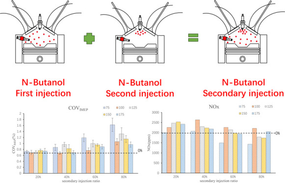
n-Butanol, as a biological alternative fuel containing oxygen, has similar physical and chemical properties to gasoline and has a wide range of sources, which has attracted more and more attention and research. Direct injection technology has been widely used in the field of internal combustion engine due to its advantages of flexibility and control ability. In this paper, the secondary injection of n-butanol engine under the mode of in-cylinder direct injection is discussed to organize stratified combustion of the mixture, optimize combustion to improve the thermal efficiency, and reduce emission. A four-cylinder four-stroke spark ignition (SI) engine was selected to carry out the secondary injection experiment of n-butanol under the excess air ratio (λ) of 1, an engine speed of 1500 r/min, and a low load, and the variables were the second injection ratio and timing. The results show that the secondary injection of n-butanol can achieve stratified combustion of the mixture, but only at a specific second injection timing such as 100°CA before compression top dead center (BTDC) or 125°CA BTDC, the combustion effect is the best. A small second injection ratio can optimize combustion, improve brake thermal efficiency, and reduce hydrocarbon and carbon monoxide emissions. When the second injection ratio is greater than 60%, it results in incomplete fuel combustion, a 3 to 4% reduction in thermal efficiency, and an increase in emissions. Coefficient of variation (COV) was increased by secondary injection, but the effect was insignificant in the small injection ratio, and it will increase with the increase of the second injection ratio. The change of particle number is mainly affected by the nuclear particle number, and with the increase of the second injection ratio, the total particulate number is more affected by the second injection timing. The second injection ratio of 40% can reduce the total particle number under the mixed-gas stratification condition.
Introduction
The increasing number of cars and outstanding environmental problems make people gradually begin to pursue a more environmentally friendly way to travel. Therefore, the development of a clean and efficient internal combustion engine has become a popular research direction. Alternative fuels, such as alcohols, dimethyl ether, and biofuels, have become an important research direction to achieve clean and efficient internal combustion engines.
Engines of vehicle are still powered mainly by fossil fuels. Alternative fuels can ease the crisis of fossil energy shortages. At the same time, alternative fuels are renewable and improve energy security. Among them, alcoholic fuels are the alternative fuels which are widely studied and can be applied in practice. Alcohol fuels can be produced by biomass evolution, which is conducive to achieving carbon neutrality and for the realization of a low-carbon path. Alcoholic fuels are liquid alternative fuels that are easy to store and transport. Compared with other fuels, alcoholic fuels have the advantages of wide source, high calorific value, and low cost. Because of the alcoholic fuels’ oxygen-containing characteristics, the emissions of particulate matter (PM) and NOx are effectively reduced.1,2 So, it has a good application effect in spark ignition (SI) engines and compression ignition engines. Alcoholic fuels have a higher latent heat of vaporization and a higher octane number, so the application of SI engines can be better applied to these characteristics.
Methanol, ethanol, and butanol are widely studied among alcohol fuels. At present, methanol and ethanol have been extensively studied and even widely applied. The bigger toxicity of methanol has certain difficulty in the practical application. In other areas, there are a large number of requirements of ethanol and butanol in agricultural biomass raw materials such as straw and wood fiber preparation.3,4 Butanol can also be as associated products of ethanol production, so the study of butanol becomes more and more important.5,6 The molecular formula of butanol is C4H9OH, and the most studied is n-butanol (CH3(CH2)3OH). Table 1 shows the comparison of fuel characteristics of n-butanol with gasoline, diesel, methanol, and ethanol.7−9 It can be seen from the comparison that the properties of n-butanol are closer to gasoline than to methanol and ethanol. Among the commonly used alcohol fuels, n-butanol has a higher calorific value, lower volatility, fewer ignition problems, better miscibility, and higher viscosity and is easier to store and transport, so it can be used more safely.
Table 1. Comparison of Properties of Various Fuels.
| gasoline | diesel | methanol | ethanol | n-butanol | |
|---|---|---|---|---|---|
| molecular formula | C4–C12 | C12–C25 | CH2OH | C2H5OH | C4H9OH |
| cetane | 0–10 | 40–55 | 3 | 8 | 25 |
| octane value | 80–99 | 20–30 | 111 | 108 | 96 |
| oxygen content (wt %) | 50 | 34.8 | 21.6 | ||
| density (g/mL) (20 °C) | 0.72–0.78 | 0.82–0.86 | 0.796 | 0.79 | 0.808 |
| autoignition temperature (°C) | ∼300 | ∼210 | 470 | 434 | 385 |
| flash point (°C) (airtight) | –45 ∼ −38 | 65–88 | 12 | 8 | 35 |
| low calorific value (MJ/kg) | 42.7 | 42.5 | 19.9 | 26.8 | 33.1 |
| boiling point (°C) | 25–215 | 180–370 | 64.5 | 78.4 | 117.1 |
| stoichiometric ratio | 14.7 | 14.3 | 6.49 | 9.02 | 11.21 |
| latent heat of evaporation (kJ/kg) (25 °C) | 380–500 | 270 | 1109 | 904 | 582 |
| flammability limits (vol %) | 0.6–8 | 1.5–7.6 | 6.0–36.5 | 4.3–19 | 1.4–11.2 |
| saturation pressure (kPa) (38 °C) | 31.01 | 1.86 | 31.69 | 13.8 | 2.27 |
| viscosity (mm2/s) (40 °C) | 0.4–0.8 (20 °C) | 1.9–4.1 | 0.59 | 1.08 | 2.63 |
Because of the good solubility of n-butanol, the current research on butanol is mainly focused on mixed fuels. Wig compared the performance and emissions of n-butanol, gasoline, and ethanol on a single-cylinder SI engine. The results showed that n-butanol was similar to gasoline in performance, the combustion temperature of butanol was lower, and the fuel atomization effect of butanol was inferior to that of ethanol.10 Yang explored the performance of gasoline–butanol mixed fuels with different proportions. The addition of butanol reduced energy consumption by 14% and emission to some extent.11 In the butanol–gasoline mixture, when the volume fraction of butanol is less than 20%, the engine performance will not be significantly affected; when the volume fraction is greater than 20%, the engine power will decrease; the addition of n-butanol can reduce the hydrocarbon (HC) and carbon monoxide (CO) emissions of the engine but increase the NOx emissions.12 Irimescu studied the visualization experiment of n-butanol on SI engine and found that n-butanol has little improvement on engine performance but can effectively reduce emissions, especially the emission of soot, and the laminar flame propagation speed of butanol is fast.13
Gu studied the effects of ignition timing and EGR rate on the emission of n-butanol–gasoline mixture on SI engines. The addition of n-butanol can reduce the emission of HC, CO, and NOx, while pure butanol will increase the emission of HC and CO and reduce the emission of NOx and PM.14 Merola studied the effects of injection timing on butanol direct injection engine combustion and soot formation by optical means.15 Liu established a neural network model to predict the performance and exhaust emissions of n-butanol–gasoline mixture on a direct injection SI engine.16 Rakopoulos studied the effects of different ratios of n-butanol–diesel mixture on the performance and exhaust emissions of direct injection diesel engines. Compared with pure diesel, butanol can effectively reduce soot emissions, slightly reduce NOx emissions, and also reduce CO emissions but will increase HC emissions. The larger the proportion of butanol, the more HC will increase. The addition of butanol will increase the specific fuel consumption, increase the effective thermal efficiency, and decrease the exhaust temperature.17 Valentino also conducted experiments on the n-butanol–diesel mixture. Compared with pure diesel, the higher spontaneous combustion resistance and higher volatility of the n-butanol mixture combined to improve emissions and reduce fuel consumption.18 Rakopoulos studied the combustion and emissions of pure diesel, biodiesel–diesel mixture, and n-butanol–diesel mixture under start-up conditions.19
According to previous studies, butanol has higher latent heat of vaporization and lower combustion temperature than diesel, which can reduce NOx emissions. Butanol contains oxygen and can also reduce soot emissions. Butanol burns faster than gasoline in SI engines and reduces particulate emissions. Therefore, from the perspective of combustion characteristics, engine performance, and exhaust emissions, butanol is the most suitable alternative fuel that does not affect engine performance and can reduce emissions.6
In SI direct injection engine, multiple injection technology is one of the optimal control methods for mixture formation and combustion process. Many scholars are also studying this aspect, among which the most widely studied is the secondary injection technology. Jose Serras-Pereira conducted a comprehensive optical study on a SI direct injection engine, comparing the images of spray development, spark discharge, and combustion of gasoline, isooctane, ethanol-n-butanol, and E10 fuel in single, secondary, and tertiary injection modes. It has been proven that multiple injection has great potential in controlling flame development, mixture formation, and influence on flow field.20 In the compressed-combustion n-butanol engine, compared with diesel, n-butanol can significantly reduce NOx and soot emissions, and multiple event fuel injection can effectively modulate the noise of n-butanol clean combustion, so that n-butanol can be applied within the full load range of the engine.21 Yadav studied the experiments of n-butanol injection in the intake port and diesel injection in the cylinder. The diesel was injected with single-pulse injection (SPI) and two-pulse injection (TPI). Under the TPI mode, NO emission was lower, the pressure rise rate was lower, and the smoke emission of the two was similar. SPI mode is suitable for medium and low loads, while TPI is suitable for high load.22 It can be seen that secondary injection can affect mixture stratification and thus combustion. For positive alcohol engines, the latent heat of n-butanol vaporization is large, which leads to poor fuel atomization effect. Therefore, it is necessary to organize reasonable mixture formation state to improve this situation. Breda et al. conducted an experimental study in a single cylinder optically accessible DISI engine fueled by n-butanol and combined with CFD numerical simulation to investigate the potential of split injection strategy to improve mixture preparation. The results show that by reducing spray penetration and reducing the duration of each pulse (maintaining the same fuel delivery), the separation injection strategy helps to improve the mixture uniformity and reduce the spray wall interaction. In particular, on shortening the first pulse (when the piston is closer to the injector tip), the mass of fuel deposits can be strongly reduced. By extending the first injection pulse and optimizing the phase of the second injection pulse, the separation injection strategy can improve the charge uniformity in the spark plug region, reduce deposition, and improve the mixture quality. Therefore, when low-steaming alcohols (such as n-butanol) are used, they are found to be a favorable strategy for improving combustion development.23 This shows that the secondary injection can reduce the amount of the first injection of n-butanol and help accelerate the atomization of n-butanol. While the second injection timing is close to the top dead center (TDC) of combustion, at this time, the high temperature will also promote the atomization and mixing of n-butanol, and the mixture stratification can be formed, which can appropriately optimize the combustion, improve thermal efficiency, and reduce emissions.
In this paper, the effects of secondary injection of n-butanol, a very potential alternative fuel, on the combustion and emission of SI engines in the direct injection mode are studied. The differences between secondary injection and single injection are compared to find the most suitable secondary injection mode, improve the thermal efficiency of the n-butanol engine, and reduce the emissions.
Experimental Setup
Engine and Instrument
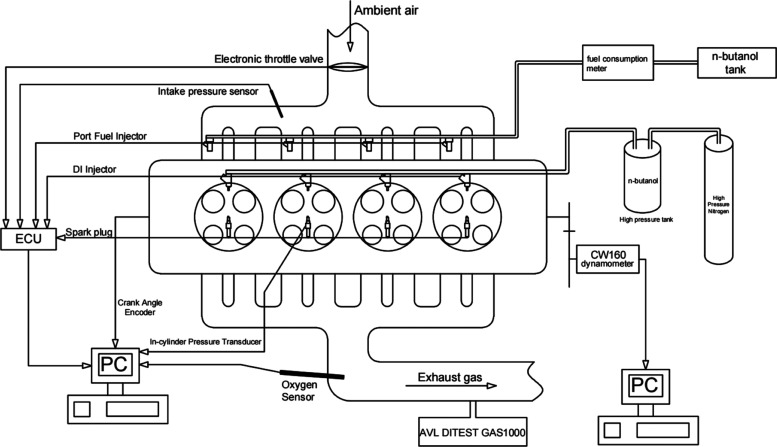
A water-cooled, four-cylinder, four-stroke SI engine is used in this experiment. Detailed parameters of the engine are shown in Table 2. Figure 1 shows the schematic diagram of the experimental device in this experiment. The high-pressure butanol injected by in-cylinder direct injection is pressurized by high-pressure nitrogen through the throttle valve in the high-pressure fuel tank. The injection pressure of butanol can be controlled by adjusting the throttle valve opening (0–15 MPa). When the engine is running with the same throttle opening, intake pressure, and λ, the fuel consumption of secondary injections in the direct injection mode can be estimated and controlled by ensuring the fuel consumption in the port injection mode.
Table 2. Main Parameters of the Engine.
| engine type | in-line, four-cylinder, combined injection |
|---|---|
| compression ratio | 9.6:1 |
| displacement | 1.984 L |
| bore × stroke | 82.5 × 92.8 mm |
| maximum power | 213 kW (5400–6500 rpm) |
| maximum torque | 380 Nm (1850–5300 rpm) |
Figure 1.
Schematic diagram of the experimental setup.
Table 3 shows the measuring parameters, measuring devices, and specifications used in this experiment. The dynamometer used in the engine is a CW160 eddy current dynamometer, which is used to control and measure the engine speed and torque. Kistler 2614B angle gauge and AVL-GU13Z24 cylinder pressure sensor are used to measure the crankshaft angle and cylinder pressure for calculation and analysis of combustion parameters. An AVL DITEST GAS1000 five-gas analyzer is used to measure the exhaust emission of the engine, which mainly focuses on CO, HC, and NOx.
Table 3. Experimental Test Equipment.
| parameters | range | precision | type |
|---|---|---|---|
| speed | 0–6000 rpm | ≤ ± 1 r/min | CW160 |
| torque | 0–600 Nm | ≤ ± 0.4 Nm | CW160 |
| crank angle | 0–720° | ≤ ± 0.5° | Kistler 2614B |
| excess air ratio (λ) | 0.700–32.767 | ≤ ± 1.5% | LAMBDA LA4 |
| cylinder pressure | 0–20 MPa | ≤ ± 0.5% | AVL-GU13-24 |
| CO | 0–15 vol % | ≤ ± 0.02% | AVL DITEST GAS1000 |
| HC | 0–30,000 ppm vol | ≤ ± 4 ppm | AVL DITEST GAS1000 |
| nitrogen oxides (NOx) | 0–5000 ppm vol | ≤ ± 5 ppm | AVL DITEST GAS1000 |
| n-butanol mass flow rate | 0.2–82 kg/h | ≤ ± 0.01 g/s | Ono Sokki DF-240 |
| PM | 0–1.0 × 10⁹ N | CAMBUSTION DMS-500 |
Experimental Procedure
This experiment selected the following small load conditions: intake pressure is 45 kPa, speed is 1500 r/min, and the fuel rail pressure of direct injection is stable at 7 MPa. The first injection timing of the secondary injection is fixed at 300°CA before compression top dead center (BTDC). The second injection timing is selected at 75, 100, 125, 150, and 175°CA BTDC, and the proportion of the second injection is set as 0, 20, 40, 60, and 80%. In order to ensure the comparability of experimental data, the total fuel consumption of n-butanol in the first injection and second injection is 2.7 kg/h. In order to control the experimental error, the cooling water temperature during engine operation is controlled at 83 ± 5 °C, the oil temperature is kept at about 90 °C, and the ignition timing is 10°CA BTDC close to the MBT (maximum brake torque timing).
Results and Discussion
Combustion Characteristics
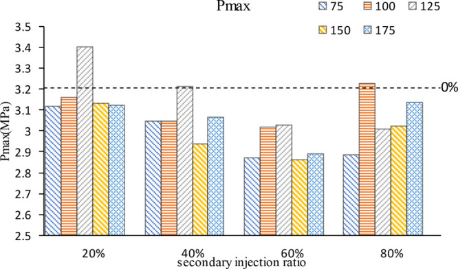
Figure 2 shows the comparison of the maximum in-cylinder pressure at different secondary injection ratios and secondary injection moments. 0% represents a single injection with 300°CA BTDC injection timing (It is true for all 0% in subsequent figures.) In general, secondary injection reduces the maximum combustion pressure in the cylinder, but at specific secondary injection ratios and timings, the maximum cylinder pressure can be higher than the single injection due to the influence of mixture stratification and air flow movement. With the increase of the secondary injection ratio, the maximum cylinder pressure decreases first and then increases, that is to say, the first n-butanol injection decreases, resulting in less combustion mixture in the early stage and a continuous decline in the maximum cylinder pressure. However, when the proportion of the second injection is too large, the mixture is partially too thick, which leads to obvious mixture stratification in the cylinder. During combustion, the combustion pressure in cylinder will increase to some extent due to the local too thick mixture. With the increase of the proportion of the second injection, the injection timing of the maximum cylinder pressure generated by the stratified combustion of the mixture changes from 125°CA BTDC to 100°CA BTDC. This may be due to the continuous increase of n-butanol in the second injection; the increase of the mixture concentration formed by the second injection made the fuel diffusion speed faster, and the increase of the injection duration caused by the increase of fuel made the air flow movement stronger, so the injection timing of the maximum cylinder pressure was late.
Figure 2.
Maximum cylinder pressure at different second injection ratios and timings.
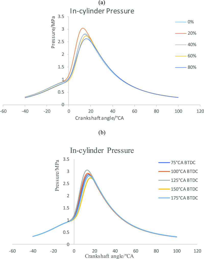
Based on the information shown in Figure 2, the maximum cylinder pressure is large at 20% secondary injection ratio, and the maximum cylinder pressure is at 125°CA BTDC injection timing, which is the best combustion performance of the secondary injection, and thus Figure 3 is drawn. Figure 3a shows the cylinder pressure curves of different second injection ratios when the second injection timing is 125°CA BTDC. Figure 3b shows the cylinder pressure curves at different injection timings when the second injection ratio is 20%. As can be seen from Figure 3a, under the condition that the second injection timing is 125°CA BTDC, the cylinder pressure generated by 20% second injection ratio is higher, the cylinder pressure curve breaks away from the compression line faster, and the maximum cylinder pressure generation timing is relatively earlier. The 40% second injection ratio is similar to the cylinder pressure without secondary injection, and with the gradual increase of the second injection ratio, the cylinder pressure gradually decreases. Figure 3b shows that when the second injection ratio is 20%, the cylinder pressure is the maximum when the second injection timing is 125°CA BTDC. With the advance of the second injection timing, the crankshaft angle corresponding to the maximum cylinder pressure first approaches TDC, then away from it, and finally approaches TDC again. When the second injection time is 125°CA BTDC, the cylinder pressure is the largest, and the crankshaft angle corresponding to the maximum cylinder pressure is the most forward. At 125°CA BTDC, the mixture may be stratified combustion, and the thick mixture area may be near the spark luge, which accelerates the combustion speed and increases the cylinder pressure. At the second injection time of 175°CA BTDC, n-butanol has sufficient time to form a uniform mixture, so that the combustion speed is accelerated, the cylinder pressure is increased, and the combustion process is moved forward. In addition, in other secondary injection timing, with the advance of injection timing, the mixture concentration zone gradually becomes thinner, the flame core formation becomes slower, the combustion speed decreases, the cylinder pressure decreases, and the combustion process shifts backward.
Figure 3.
(a) Cylinder pressure at different second injection ratios. (b) Cylinder pressure at different second injection timings.
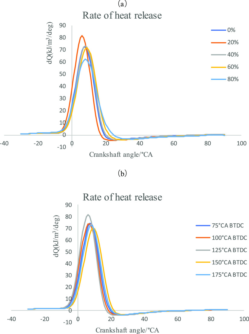
Figure 4a,b shows the heat release rate curves under different second injection ratios and second injection timings. As can be seen from Figure 4a, the maximum heat release rate first increases and then decreases with the increase of the second injection ratio, and the maximum heat release rate is reached when the second injection ratio is 20%, and the overall heat release rate curve is relatively advanced. This trend is consistent with the cylinder pressure. This phenomenon shows that the concentration region of the stratified mixture at 20% second injection ratio can accelerate the formation of the flame core, and the homogeneous mixture composed of the remaining 80% n-butanol can also ensure a relatively fast and complete combustion. When the injection ratio increases to 80%, although the overly concentrated mixture can form the flame core faster, due to the influence of the concentrated mixture and the thin homogenized mixture, the maximum heat release rate decreases, the after-combustion increases, and the combustion process is longer. Figure 4b reflects the change of heat release rate under the same second injection ratio but different second injection timing. It can be seen from the figure that with the advance of the second injection timing, the maximum heat release rate first increases, then decreases, and then increases, while the moment of the maximum heat release rate first gradually approaches the TDC, then moves away from the TDC, and then approaches the TDC at the second injection timing of 175°CA BTDC. It can be seen that 125°CA BTDC is the fastest combustion time of the layered mixture formed by the secondary injection, while the second injection timing of 175°CA BTDC is relatively earlier, and the n-butanol injected by the second injection can get a longer formation time of the mixture, so the combustion speed is closer to the homogeneity, and the combustion speed will be faster than that of the layered mixture formed by the poor injection timing. Therefore, the maximum heat release rate is higher at this time, and the crankshaft angle corresponding to the maximum heat release rate is close to the TDC.
Figure 4.
(a) Rate of heat release at different second injection ratios. (b) Rate of heat release at different second injection timings.
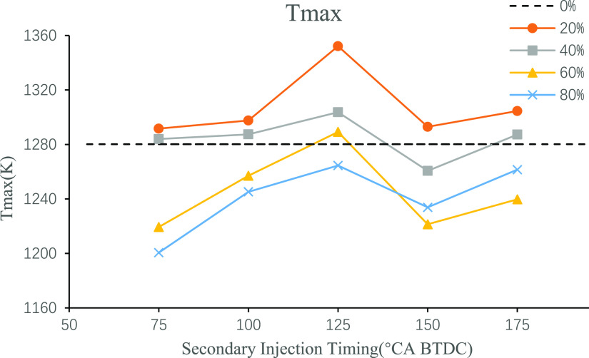
Figure 5 shows the curve of the maximum in-cylinder combustion temperature at different second injection timings and ratios. It is obvious from the figure that at all injection ratios studied in this paper, the second injection timing of 125°CA BTDC makes the maximum combustion temperature reach the local maximum value, while under the condition that the ratio is not particularly large, this combustion temperature can reach the global maximum value. Under the condition of a large second injection ratio, due to the relatively large latent heat of vaporization of n-butanol, the optimized combustion performance achieved by stratified combustion is not as good as that achieved by advanced injection to fully atomized and mixed combustion of n-butanol. Therefore, the in-cylinder temperature achieved by advance injection is higher than that by 125°CA BTDC injection timing. Compared with the single injection, secondary injection in 20%, 40% in addition to 150°CA BTDC and 125°CA BTDC at 60% of the maximum combustion temperature is higher. This is to say, an appropriate small second injection ratio can optimize combustion and increase the maximum in-cylinder combustion temperature. A large second injection ratio will make the fuel atomization not good, and the combustion is not sufficient, thus reducing the combustion temperature.
Figure 5.
Maximum temperature of combustion under different second injection timings and ratios.
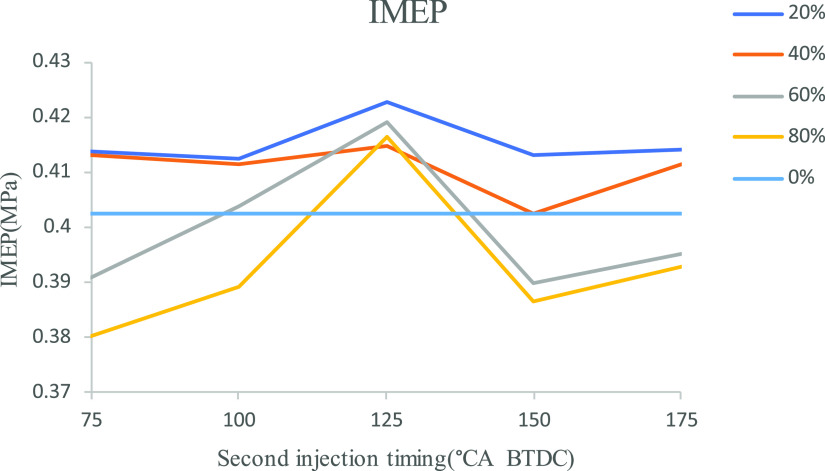
Figure 6 shows the change curve of indicated mean effective pressure (IMEP). It can be seen from the figure that IMEP reaches its maximum at the second injection timing of 125°CA BTDC, and the secondary injection at this timing can increase IMEP. At the same time, it can be seen that the second injection ratio of 20 and 40% can increase the IMEP. It can be seen that the injection timing of 125°CA BTDC is the best stratification timing, at which the stratified mixture can burn quickly to obtain more power. At the same time, no matter how the injection timing is, the stratified combustion of the mixture can be improved under the second injection ratio of 20 and 40%. However, with the increase of the second injection ratio, IMEP gradually decreases and even lower than the single injection when the second injection ratio is too large.
Figure 6.
IMEP under different second injection timings and ratios.
Coefficient of variation (COV) represents cyclic variations of engine combustion and is one of the engine performance indicators. Reducing such variations can improve the engine’s working stability, power performance, and economy performance. COVIMEP is defined as follows:
where
where x is IMEP and N = 200 is the number of sampling cycles in this study.
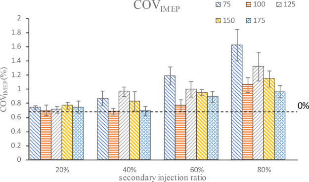
Figure 7 shows the comparison of the cyclic variation under different second injection ratios and injection timings. It can be seen that the secondary injection will increase the cyclic variation of combustions, and with the continuous increase of the second injection ratio, the cyclic variation will increase more, and the cyclic variation between different injection timings will become more and more different. That is to say, the secondary injection achieves stratified combustion, but stratified combustion increases the COVIMEP. The greater the proportion of stratified parts, the greater the influence on the COVIMEP. It can also be seen from the figure that COVIMEP increases with the increase of second injection ratio, but COVIMEP changes at different second injection timings are consistent at all injection ratios; with the advance of the injection timing, COVIMEP first decreases, then increases, and then decreases again, and the COVIMEP minimum injection timing is 100°CA BTDC. That is to say, there is an optimal second injection timing in the stratified combustion, which can make COVIMEP small, and then as the injection timing advances, the mixture tends to be homogenized, making the COVIMEP continuously smaller. Therefore, in the realization of secondary injection, in order to make the combustion more stable, a relatively small proportion of second injection should be selected.
Figure 7.
COVIMEP at different second injection ratios and timings.
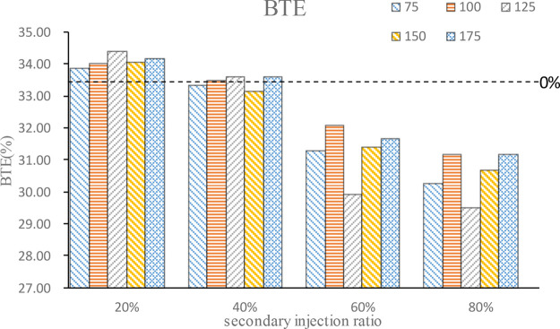
Figure 8 shows the comparison of the brake thermal efficiency (BTE) of combustion at different secondary injection ratios and timings. As can be seen from the figure, the BTE increases under the condition of an appropriate small proportion of secondary injection, but with the gradual increase of the second injection ratio, BTE will continue to decrease. When the second injection ratio exceeds 40%, the BTE is smaller than that of single injection. Under all injection ratio conditions, BTE increases first, then decreases, and then increases again; with the advance of the injection timing, there is a local maximum value of BTE at 100°CA BTDC or125°CA BTDC. According to the previous analysis, the mixture at this time is stratified combustion, that is to say, certain stratified combustion helps improve the engine’s BTE. However, the stratified combustion formed by the mixture represents the uneven distribution of the mixture, so a large second injection ratio will lead to incomplete fuel combustion, and BTE decreases, and then with the advance of the second injection timing, BTE increases gradually.
Figure 8.
BTE at different second injection ratios and timings.
Emission Characteristics
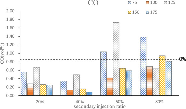
Figure 9 shows the CO emission at different secondary injection ratios and timings. It can be seen from the figure that secondary injection can reduce CO emission, but a large proportion of secondary injection will reduce CO emission to a low degree and even increase CO emission. On the whole, 40% injection ratio is the most obvious for reducing CO emission. With the advance of the second injection timing, CO emission first decreases and then increases and then decreases again. At a relatively late injection timing, the mixture is locally too thick, which leads to the high CO emission. Then, there is an optimal injection timing to achieve the best stratified combustion effect, and the combustion temperature is higher, which promotes the oxidation of CO and reduces CO emission. On the whole, the mixture formed by the first injection of n-butanol under the condition of secondary injection is a thin mixture, which leads to CO decrease. When the proportion of the second injection gradually increases, the stratified combustion region of the mixture is too thick, resulting in a large amount of CO and increasing total CO emission.
Figure 9.
CO emission.
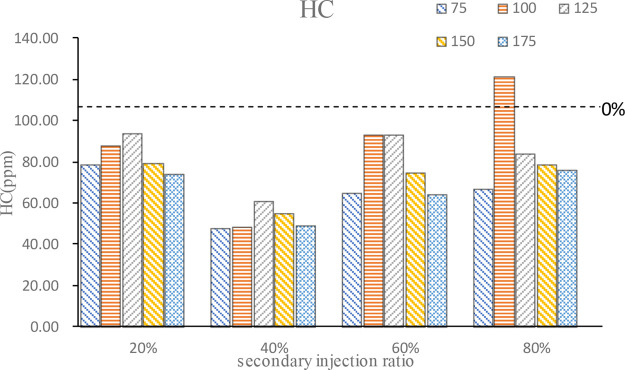
HC emission is similar to CO emission for the same reason, as shown in Figure 10. However, except for the 100°CA BTDC at 80% ratio, secondary injection can effectively reduce HC emission under other conditions. Apparently, the 40% second injection ratio makes the best progress to reduce HC emission; at this time, the secondary injection implements the mixture stratified combustion, the mixture concentration of the combustion chamber wall part is low, and wall quenching and narrow gap effect smoldering HC emission is reduced. When the secondary injection ratio is large, the mixture concentration area will be too thick, fuel cannot complete combustion and lead the HC emission increase. It also can be seen from the figure that in most cases, HC emission is higher at the second injection timing at 100°CA BTDC or 125°CA BTDC. With the advance of the second injection timing, fuel diffusion is gradually uniform, and HC emission decreases. However, with the late second injection timing, n-butanol may collide with the wall during injection, which causes most of the fuel on the wall to burn after, leading to less HC emission at this time.
Figure 10.
HC emission.
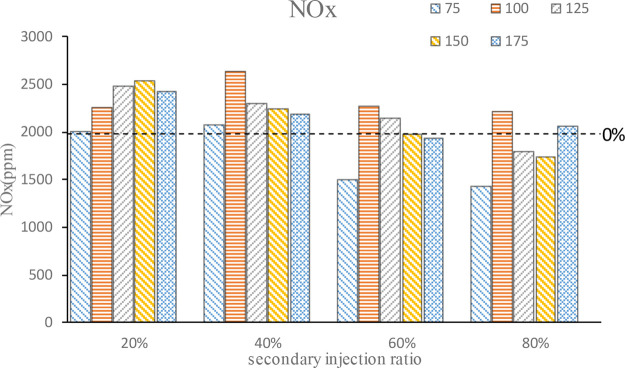
Figure 11 is the NOx emission, from which it can be seen that in addition to a large n-butanol secondary injection ratio, secondary will increase the NOx emission. In a small second injection ratio, the NOx emission increases first and then decreases. According to the trend of Tmax, the NOx generated at this time is caused by high temperature, which is consistent with the change trend of temperature in the cylinder. Under 80% second injection ratio, the core area of the mixture is too thick and the incomplete combustion leads to less NOx emission. Then, with the advance of the second injection timing, the mixture combustion effect is better and stratified combustion is realized, resulting in higher local temperature and increased NOx emission. As the injection timing continues to advance, due to large n-butanol gasification of latent heat, atomization evaporation heat results in lower temperature in the cylinder and NOx reduction; but when the injection timing is too early, the mixture is gradually close to the homogeneous, and the local thick area is gradually less, making the combustion more complete and the combustion temperature higher, so the NOx emission increases. In general, a small second injection ratio produces a better stratified combustion effect and high combustion temperature, leading to more NOx emission. A large second injection ratio leads to the local mixture area being too thick and n-butanol atomization evaporation heat absorption to reduce the temperature in the cylinder, resulting in less NOx emissions.
Figure 11.
NOx emission.
Figure 12 shows the TPN, NPN (nuclear particulate number), and APN (aggregated particulate number) at different secondary injection ratios and timings. It can be seen from the figure that 40% secondary injection ratio can reduce particulate emissions. Meanwhile, under the condition of secondary injection, advancing the second injection timing, such as 150°CA BTDC or 175°CA BTDC, can also reduce particulate emissions to a certain extent. With the increase of the secondary injection ratio, the variation of total particulate emissions with the second injection timing increases. The change of TPN is similar to the change of NPN, that is, the total particulate emissions is mainly related to the change of nuclear particulate emissions and is less affected by the change of aggregated particulate emissions. This is mainly because the amount of aggregated particulate is relatively small. Except for the excessively large secondary injection ratio and too late injection timing of the case of 80%-100°CA BTDC, the emission of aggregated particles changes little with the secondary injection timing, and the order of magnitude is basically below 1 × 10⁴. The change of particle number is mainly affected by the nuclear particle number, and with the increase of the second injection ratio, TPN is more affected by the second injection timing. The second injection ratio of 40% can reduce the total particle number under the mixed gas stratification condition.
Figure 12.
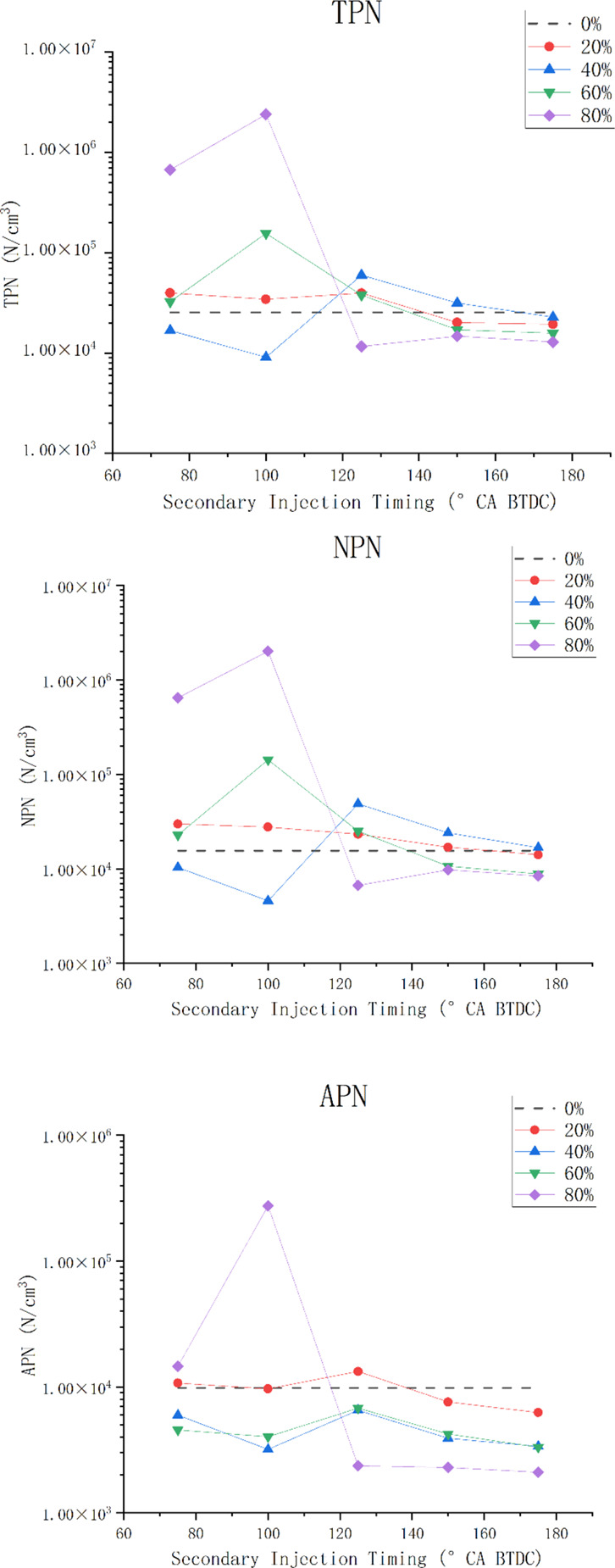
Particulate matter emission.
Conclusions
All experiments have been carried out on an in-line four-cylinder SI engine in this article. Under the condition of excess air coefficient of 1, the difference of combustion and emission between single injection and secondary injection of n-butanol was compared. The combustion and emission of n-butanol under the condition of secondary injection with different injection ratios and timings were also investigated. The conclusions are as follows:
-
1.
Secondary injection of n-butanol can achieve stratified combustion of the mixture, which will lead to a drop in cylinder pressure, but a small second injection ratio (20, 40%) will increase the combustion temperature and IMEP, and when the second injection timing is 100°CA BTDC or 125°CA BTDC, a better stratified combustion effect can be achieved, which increases the cylinder pressure, the maximum combustion temperature, and IMEP.
-
2.
Secondary injection will lead to the increase of COV, and with the larger second injection ratio, the COV will be larger. A small second injection ratio can increase BTE slightly, and with the increase of the second injection ratio, BTE will decrease significantly.
-
3.
A small second injection ratio can effectively reduce CO and HC emissions but will increase NOx emissions. Excessive proportion of secondary injection will lead to fuel wall collision, incomplete combustion, and other phenomena, which make the combustion effect worsen and the emission increase.
-
4.
The TPN is greatly affected by the change of NPN. With the increase of the proportion of the second injection, the nuclear particulate and total particulate emissions are affected greatly by the secondary injection timing. Except for the 80%-100°CA BTDC, the change of APN is less affected by secondary injection and is mainly affected by the injection ratio, and the order of magnitude is always relatively low.
Glossary
Nomenclature
- SI
spark ignition
- BTE
brake thermal efficiency
- BTDC
before compression top dead center
- λ
excess air ratio
- COV
coefficient of variations
- TPN
total particulate number
- APN
aggregated particulate number
- HC
hydrocarbon
- CO
carbon monoxide
- NOx
nitrogen oxides
- IMEP
indicated mean effective pressure
- MBT
minimum advance of best torque
- NPN
nuclear particulate number
This research was funded by the National Natural Science Foundation of China (grant number 51976076).
The authors declare no competing financial interest.
References
- Balamurugan T.; Nalini R. Experimental investigation on performance, combustion and emission characteristics of four stroke diesel engine using diesel blended with alcohol as fuel. Energy 2014, 78, 356. 10.1016/j.energy.2014.10.020. [DOI] [Google Scholar]
- Sukjit E.; Herreros J. M.; Dearn K. D.; Tsolakis A.; Theinnoi K. Effect of hydrogen on butanol–biodiesel blends in compression ignition engines. Int. J. Hydrogen Energy 2013, 38, 1624. 10.1016/j.ijhydene.2012.11.061. [DOI] [Google Scholar]
- Bettina S.-B.; José M.; Sonja L.; Peter D. Butanol fermentation. Environ. Technol. 2013, 34, 1691. 10.1080/09593330.2013.827746. [DOI] [PubMed] [Google Scholar]
- Ávila M.; Rochón E.; Lareo C. Improvements in the formulation of sugarcane-sweet sorghum juices fermentation media for enhanced isopropanol and butanol production. Biomass Convers. Biorefin. 2021, 13, 4575. 10.1007/s13399-021-01458-1. [DOI] [Google Scholar]; (prepublish):
- Green E. M. Fermentative Production of Butanol—The Industrial Perspective. Curr. Opin. Biotechnol. 2011, 22, 337–343. 10.1016/j.copbio.2011.02.004. [DOI] [PubMed] [Google Scholar]
- Jin C.; Yao M.; Liu H.; Chia-fon F. L.; Ji J. Progress in the Production and Application of n-Butanol as a Biofuel. Renewable Sustainable Energy Rev. 2011, 15, 4080–4106. 10.1016/j.rser.2011.06.001. [DOI] [Google Scholar]
- He B. Q.; Chen X.; Lin C. L.; et al. Combustion characteristics of a gasoline engine with independent intake port injection and direct injection systems for n-butanol and gasoline. Energy Convers. Manage. 2016, 124, 556–565. 10.1016/j.enconman.2016.07.053. [DOI] [Google Scholar]
- Wang Z.; Liu H.; Long Y.; et al. Comparative study on alcohols–gasoline and gasoline–alcohols dual-fuel spark ignition (DFSI) combustion for high load extension and high fuel efficiency. Energy 2015, 82, 395–405. 10.1016/j.energy.2015.01.049. [DOI] [Google Scholar]
- Veloo P. S.; Wang Y. L.; Egolfopoulos F. N.; Westbrook C. K. A comparative experimental and computational study of methanol, ethanol, and n-butanol flames. Combust. Flame 2010, 157, 1989–2004. 10.1016/j.combustflame.2010.04.001. [DOI] [Google Scholar]
- Wigg B.; Coverdill R.; Lee C.-F.; Kyritsis D.. Emissions Characteristics of Neat Butanol Fuel Using a Port Fuel-Injected, Spark-Ignition Engine; SAE international 2011-01-0902.
- Yang J.; Wang Y.; Feng R.. The Performance Analysis of an Engine Fueled with Butanol-Gasoline Blend; SAE international 2011-01-1191.
- Yang J.; Yang X.; Liu J.; Han Z.; Zhong Z.. Dyno Test Investigations of Gasoline Engine Fueled with Butanol-Gasoline Blends; SAE International 2009-01-1891.
- Irimescu L.; Marchitto S. S.; Merola C.; Tornatore G.; Valentino G. Combustion process investigations in an optically accessible DISI engine fuelled with n-butanol during part load operation. Renewable Energy 2015, 77, 363–376. 10.1016/j.renene.2014.12.029. [DOI] [Google Scholar]
- Xiaolei G.; Huang Z.; Cai J.; Gong J.; Wu X.; Lee C.-F. Emission characteristics of a spark-ignition engine fuelled with gasoline-n-butanol blends in combination with EGR. Fuel 2012, 93, 611–617. 10.1016/j.fuel.2011.11.040. [DOI] [Google Scholar]
- Merola S. S.; Irimescu A.; Marchitto L.; Tornatore C.; Valentino G. Effect of injection timing on combustion and soot formation in a direct injection spark ignition engine fueled with butanol. Int. J. Engine Res. 2017, 18, 490–504. 10.1177/1468087416671017. [DOI] [Google Scholar]
- Liu Z.; Zuo Q.; Wu G.; Li Y. An artificial neural network developed for predicting of performance and emissions of a spark ignition engine fueled with butanol–gasoline blends. Adv. Mech. Eng. 2018, 10, 1–11. 10.1177/1687814017748438. [DOI] [Google Scholar]
- Rakopoulos D. C.; Rakopoulos C. D.; Giakoumis E. G.; Dimaratos A. M.; Kyritsis D. C. Effects of butanol–diesel fuel blends on the performance and emissions of a high-speed DI diesel engine. Energy Convers. Manage. 2010, 51, 1989–1997. 10.1016/j.enconman.2010.02.032. [DOI] [Google Scholar]
- Valentino G.; Corcione F. E.; Iannuzzi S. E.; Serra S. Experimental study on performance and emissions of a high speed diesel engine fuelled with n-butanol diesel blends under premixed low temperature combustion. Fuel 2012, 92, 295–307. 10.1016/j.fuel.2011.07.035. [DOI] [Google Scholar]
- Rakopoulos C. D.; Dimaratos A. M.; Giakoumis E. G.; Rakopoulos D. C. Study of turbocharged diesel engine operation, pollutant emissions and combustion noise radiation during starting with bio-diesel or n-butanol diesel fuel blends. App. Energy 2011, 88, 3905–3916. 10.1016/j.apenergy.2011.03.051. [DOI] [Google Scholar]
- Serras-Pereira J.; Aleiferis P. G.; Richardson D. An experimental database on the effects of single- and split injection strategies on spray formation and spark discharge in an optical direct-injection spark-ignition engine fuelled with gasoline, iso-octane and alcohols. Int. J. Engine Res. 2015, 16, 851–896. 10.1177/1468087414554936. [DOI] [Google Scholar]
- Han X.; Yang Z.; Wang M.; Tjiong J.; Zheng M. Clean combustion of n-butanol as a next generation biofuel for diesel engines. Appl. Energy 2017, 198, 347–359. 10.1016/j.apenergy.2016.12.059. [DOI] [Google Scholar]
- Yadav J.; Ramesh A. Comparison of Single and Multiple Injection Strategies in a Butanol Diesel Dual Fuel Engine. J. Energy Resour. Technol. 2018, 140, 072206 10.1115/1.4039546. [DOI] [Google Scholar]
- Breda S.; D’Orrico F.; Berni F.; d’Adamo A.; Fontanesi S.; Irimescu A.; Merola S. S. Experimental and numerical study on the adoption of split injection strategies to improve air-butanol mixture formation in a DISI optical engine. Fuel 2019, 243, 104–124. 10.1016/j.fuel.2019.01.111. [DOI] [Google Scholar]


