

 Content of this journal is licensed under a
 Abstract
Objective:
This study aimed to introduce a method to extract the 3-dimensional spatial position of the femoral head implant from 2-dimensional fluoroscopic projections, allowing surgeons to assess fixation much more accurately and prevent cut-out complications in proximal femoral nailing.
Methods:
To define a safety region for the tip in the femoral head, a novel 3-dimensional distance-based risk parameter called TSD3D was introduced. An intersection algorithm was developed that solely takes the fluoroscopic anteroposterior and lateral distances to reveal the 3-dimensional location of the screw or Kirschner wire tip, enabling the utilization of the 3-dimensional parameter. Orthogonal perspectives of 6 femur proximal bone substitutes with randomly inserted Kirschner wires were imaged under fluoroscopy. The developed algorithm was used to calculate the implant tip location in 3-dimensional from 2-dimensional images for each case. Algorithm accuracy was validated with the computed tomography-obtained 3-dimensional models of the same femur substitutes.
Results:
The newly introduced risk parameter successfully visualizes 3-dimensional safety regions. Utilizing the 2-dimensional fluoroscopic distances as inputs to the algorithm, the 3-dimensional position of the implanted Kirschner wire tip is calculated with a maximum of 9.8% error for a single Cartesian-coordinate measurement comparison.
Conclusion:
By incorporating the newly introduced 3-dimensional risk parameter, surgeons can more precisely evaluate the position of the implant and avoid cut-out complications, instead of relying solely on misleading 2-dimensional fluoroscopic projections of the femoral head.
Keywords: Cut-out, Femur, Proximal nailing, Tip-apex distance, Fluoroscopy, Intertrochanteric fracture
Highlights
The 2D fluoroscopic projections of the cephalomedullary nail are misleadingX
A novel 3D distance-based risk parameter is introduced for intraoperative use
A 2D/3D registration algorithm is developed for parameter validation
3D safety regions are visualized using the newly introduced risk parameter
The introduced 3D parameter can allow accurate implant safety assessment
Introduction
Cephalomedullary fixation systems are commonly used surgical implants to restore intertrochanteric hip fractures (AO/OTA 31A).1 The most prevalent failure mode of a cephalomedullary implant is the cut-out complication and is typically followed by the collapse of the femoral head or penetration of the screw tip into the hip joint, which can lead to patient morbidity or mortality at significant rates (16%-23%).2-4 The post-operative cut-out complication is mainly linked to the initial position of the screw tip inside the femoral head, a correlation documented and researched comprehensively in the literature.2,5-10
To quickly assess the safety of the implant tip position or the inserted Kirschner wire (K-wire) position, fluoroscopic images are consulted.11,12 However, the inherent limitation of fluoroscopy is that only one perspective can be viewed at a time and the provided images are 2-dimensional (2D), which does not properly convey spatial 3-dimensional (3D) information. Typically, orthogonal anteroposterior (AP) and lateral (Lat) projections of the spherical femoral head are imaged, and a risk evaluation based solely on these 2 projections is carried out without consulting a third-angle perspective. However, it is demonstrated in the literature that for a given surgical screw confined inside the orthogonal projections of the femoral head in fluoroscopy, there is a 21.4% chance that the tip might be residing outside the cortex. In other words, the screw is penetrating the hip joint,13,14 which is a substantial risk and a strong testament to the misleading nature of 2D risk assessment. To avoid cut-out, the implant tip must reside in a safety volume inside the femoral head defined by the intersection of a proper upper and lower bound. But due to the 2D nature of imaging, the distance-based risk parameters that define this volume are also confined to 2D. Tip-apex distance (TAD),2 calcar-based TAD,9 TADX,14 and tip-surface distance (TSD)13 are among the 2D risk parameter definitions that have been discussed in the literature.
The fallacies of using simple 2D distances to understand the actual 3D position of the tip and its relative position to the imaginary ideal tip volume and the hip joint have been demonstrated in the literature.13,14 In this study, the discussion is moved to utilizing 3D risk parameters for the creation of a meaningful safety region inside the 3D space. For the upper bound definition of the safety region, TAD is utilized. The TAD is a convenient distance-based risk parameter for implant tip safety assessment, quickly calculated by summing the implant tip to femur apex distances in AP and Lat projections.2 A significant number of studies in the literature vouch for the use of TAD for predicting cut-out.2,3,5-8,25-27 TAD, even though based on a 2D mathematical calculation, can still define an acceptable 3D volume when utilized in conjunction with a proper lower bound.14
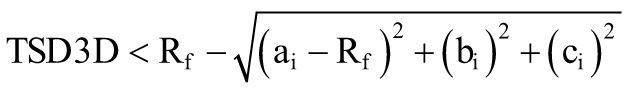
Very few attempts have been made to mathematically define the lower bound for the safety volume. TADX is proposed,14 which dictates how proximal the implant tip can be to the apex of the femur using the orthogonal projection distance on the neck centerline. While TADX respects the 2D limitation of imaging, it still falls short of defining an ideal 3D volume.14 Another 2D lower bound definition is the TSD,13 which dictates the proximality of the tip to the outer cortex and also suffers similar nonideal volumetric problems as TADX. Therefore, to address this shortcoming, TSD3D, a 3D distance-based risk parameter that also has intuitive spherical symmetry inside the femoral head, is put forth in this study as a lower bound to the safety volume. This new distance risk parameter is put forth to designate the minimum distance the screw tip can be proximal to the outer cortex in 3D space, considering the spherical anatomy of the femur head.
Ideally, the surgeon should have access to the visualization of the tip in 3D, such that the utilization of misleading 2D risk parameters can be completely discarded in favor of 3D definitions. However, intraoperative 3D visualization is not possible with solely fluoroscopy and without any surgical assist systems15-20 or 2D/3D registration systems.21-23 The primary goal of this study is to shift the implant safety assessment discussion from 2D to 3D. In this vein, a novel 3D distance-based risk parameter is introduced to assess the cut-out risk for femoral head implants. To unlock the use of this parameter, an alternative and easily accessible 3D appraisal method based on a 2D/3D correspondence-based registration framework, solely using the fluoroscopic orthogonal projections, is devised and investigated. The 3D construction and visualization of the optimal tip volume inside the femoral head relative to the implant tip is another critical novelty of this study, which has not been discussed in the literature yet. Ideally, the surgeon should have access to the visualization of the tip in 3D, such that the utilization of misleading 2D risk parameters can be completely discarded in favor of 3D definitions. However, intraoperative 3D visualization is not possible with solely fluoroscopy and without any surgical assist systems15-20 or 2D/3D registration systems.21-23 The primary goal of this study is to shift the implant safety assessment discussion from 2D to 3D. In this vein, a novel 3D distance-based risk parameter is introduced to assess the cut-out risk for femoral head implants. To unlock the use of this parameter, an alternative and easily accessible 3D appraisal method based on a 2D/3D correspondence-based registration framework, solely using the fluoroscopic orthogonal projections, is devised and investigated. The 3D construction and visualization of the optimal tip volume inside the femoral head relative to the implant tip are another critical novelty of this study, which has not been discussed in the literature yet.
Materials and Methods
Algorithm for safety assessment
The imaging problem can be simplified to identifying the position of a point (implant tip) inside a sphere with respect to a designated point (apex) on a properly oriented sphere surface (outer cortex of the femoral head). Therefore, to allow the use of TSD3D in this study, the 2D images are readily matched to a simplified 3D representation model. An intersection algorithm is developed to reveal the 3D position of the implant tip, extracted, and approximated from merely the AP and Lat views.
Assuming perpendicular fluoroscopic imaging perspectives, in which the AP and Lat perspectives are orthogonal to each other and intersect at the imaginary femoral head midline that runs along the +X axis of the Cartesian coordinate system, the AP perspective is the projection of the XZ plane, and the Lat perspective is the projection of the XY plane. After the placement of the K-wire or screw, the orthogonal fluoroscopy perspectives of the femoral head are imaged according to the routine procedures. The algorithm then takes the 2D coordinates of the tip in the AP and Lat views as arguments for 3D representation. By placing the apex on the Cartesian (0,0,0) origin, a femoral head with a radius Rf will have its center located at the Cartesian location (Rf ,0,0). Thus, the X, Y, and Z coordinate information required for determining the 3D spatial location of the tip inside the femoral head in the desired orientation is contained in the AP and Lat images.
To visualize the safety volume, first, a point grid with a designated pitch distance is created that envelops the complete femoral head. The grid represents the possible implant tip locations. A 0.2 mm pitch distance is chosen for the algorithm as it is a small-enough resolution to both properly visualize and estimate the volume of the safety region. The pitch distance cubed will estimate the unit volume for one grid point. For a given grid point at (ai, bi, ci ), the parametric safety volume will be created by the intersection of the chosen TSD3D lower bound and TAD upper bound (Figure 1):
Figure 1.

Mathematical definition of the safety region is shown; ideal tip volume created with TAD < 25 mm and TSD3D > 5 mm for a 47 mm diameter femur is illustrated. Left: The upper-lower bound definitions are depicted in 3D with respect to the femoral head. Right: The AP-Lat perspectives of the femoral head; the optimal tip region is shown as the intersection of 2 mathematical bound definitions. 3D, three-dimensional; TAD, tip-apex distance.
 |
(1) |
 |
(2) |
A sample ideal tip safety region created with TAD < 25 mm and TSD3D > 5 mm inside a spherically approximated femoral head with a 47 mm diameter is illustrated in Figure 1.
The algorithm corrects for the magnification factor using the recorded K-wire or screw thickness in both imaging perspectives as the real thickness is a known parameter. Given the femur diameter, the algorithm generates a wireframe representation of the femoral head sphere and places the safety region at the correct orientation around the apex. After the tip’s X, Y, and Z coordinates are determined, the algorithm calculates whether the tip position is inside the safety region using the minimum distance calculation in Eqs. (1) and (2). For this study, the algorithm is programmed in the Python language, and the interactable 3D spatial graph of the tip position is generated with the help of the open-source NumPy library.
Preliminary validation
For preliminary validation of the 2D/3D registration algorithm and the proposed safety assessment methodology, 2.5 mm diameter K-wires are inserted into artificial femur substitutes (Sawbones AB, Malmo, Sweden). Three different femurs (2 left and 1 right) are each utilized twice for different K-wire insertion scenarios. The K-wire/femur constructs are first scanned via computed tomography (CT) with a Siemens SOMATOM Definition Flash(Munich, Germany) (0.6 mm slice thickness, 38.4 mm collimation width, 0.3-0.4 mm pixel spacing) and reconstructed as virtual 3D stereolithography (STL) models using open-source medical image segmentation software (3D Slicer28). The STL models are then imported into computer-aided design (CAD) software (Siemens NX v1863, Plano, Tex, USA). The K-wire tip is identified for each model, and the X, Y, and Z coordinates of the tips are recorded. The tip location obtained via this 3D reconstruction procedure is taken as the benchmark comparison location. After CT scanning, the K-wire/femur constructs are radiographed in AP and Lat perspectives with a C-arm fluoroscopy (Siemens, Cios Connect, 0.144/0.144-pixel spacing, unity magnification).
To validate the accuracy of the proposed intersection algorithm, the necessary distance inputs are measured on the fluoroscopic images, and the developed program is run to reveal the algorithm-calculated 3D position of the tip. The benchmark tip coordinates from the CAD software are compared to the separately measured fluoroscopic distances for comparison, and the errors are reported for each Cartesian coordinate axis. The AP and Lat distances are calculated utilizing image analysis software (IAS) (Digimizer, MedCalc Software, Ostend, Belgium). The complete methodology followed is summarized in Figure 2.
Figure 2.

The algorithm validation methodology flowchart is illustrated. Mimicking the intraoperative radiography procedure, the 2D X, Y, and Z coordinates are extracted and compared with the CAD software–identified benchmark 3D location of the tip for error calculation. 2D, 2-dimensional; 3D, 3-dimensional; CAD, computer-aided design.
Results
The tip coordinate measurements and the calculated errors are reported in Table 1. Among the 3 different femurs utilized in this study, A and C are left femurs, while B is a right femur. The pixel spacings for the 6 CT scans are between 0.3 mm and 0.4 mm. Thus, the maximum error tolerance for the CAD-based 3D measurement is designated as ±0.400 mm. Similarly, the 2D measurements conducted in the IAS have a ±0.144 mm tolerance, in accordance with the fluoroscopic pixel spacing.
Table 1.
Tip coordinate measurements and the calculated errors for 6 different K-wire insertion cases
|
Case |
R/L |
CT measurement | Fluoroscopy measurement | % Error | ||||||
|---|---|---|---|---|---|---|---|---|---|---|
| X3D | Y3D | Z3D | X2D | Y2D | Z2D | X | Y | Z | ||
| A1 | L | 6.97 | 14.28 | 13.33 | 6.43 | 14.46 | 13.65 | 8.02 | 0.31 | 2.43 |
| A2 | L | 15.59 | −2.48 | 7.04 | 15.73 | −2.33 | 7.07 | 0.88 | 1.54 | 0.34 |
| B1 | R | 10.97 | 4.81 | −11.61 | 12.04 | 4.58 | −11.32 | 9.28 | 1.26 | 2.55 |
| B2 | R | 15.11 | −3.95 | 10.25 | 14.93 | −4.06 | 9.29 | 1.19 | 0.70 | 9.85 |
| C1 | L | 4.77 | −8.51 | 8.53 | 5.17 | −7.79 | 9.28 | 8.08 | 2.20 | 8.29 |
| C2 | L | 14.60 | 4.20 | 8.69 | 15.22 | 3.83 | 8.25 | 4.15 | 2.28 | 5.19 |
The radii of the femoral heads are measured in each 2D AP and Lat view in the IAS by fitting a circle to the proximal femur curvature. The radii of femurs A, B, and C are approximated as 25.58 mm, 25.07 mm, and 25.31 mm, respectively, by averaging the 4 recorded radii across 2 AP and 2 Lat radiographs for each. Among the 6 cases, the maximum calculated percent radius difference between the AP and Lat radius of a femur is 3.79%, which is a testament to the consistency of approximating the proximal femoral head as a circle between the orthogonal perspectives.
The K-wire diameters measured on the image analysis software for all the radiographs are in the 2.5 ± 0.144 mm range, confirming the unity magnification. All recorded K-wire diameter measurements are rounded to 2.50 mm as algorithm inputs for validation. The maximum error recorded for a single coordinate measurement comparison in Table 1 is 9.28%, which indicates that the 3D location of the implant tip can be approximated with relative precision.
In Figure 3, the 2D versus 3D tip measurement procedure for the A1 K-wire insertion case is illustrated in detail, which is a critical example of a highly misleading case. The tip resides inside the 2D orthogonal views but is outside the outer cortex in 3D. Establishing the accuracy of the adopted 2D/3D registration methodology, the 3D distance-based risk parameters can then be brought into the discussion. Using the lower TSD3D bound (Eq. 1) and upper TAD bound (Eq. 2) definitions, 3 different safety volumes are investigated:
Figure 3.

Tip location comparison for the A1 case is shown. The fluoroscopic distances are measured on the AP and Lat radiograph with unity magnification in the IAS. The 3D location of the tip is identified in the CAD software. 3D, 3-dimensional; AP, anteroposterior; CAD, computer-aided design; IAS, image analysis software; Lat, lateral.
TSD3D > 5 mm ∩ TAD < 25 mm(3)
TSD3D > 5 mm ∩ TAD < 30 mm(4)
TSD3D > 7.5 mm ∩ TAD < 25 mm(5)
The volumes generated by the 3 sets of limits are plotted in Figure 4 across the anatomical range of femur diameters (34-60 mm); the volumes are visualized for the 34, 47, and 60 mm cases. A positive correlation is observed between the safety volume and the femur diameter.
Figure 4.

Safety volumes are compared using 3 different upper-lower bound definitions across the anatomical range for femur head sizes.
It can be inferred from Figure 4 that depending on the chosen upper and lower bounds the safety volume can substantially vary; therefore, for a surgical computer-assist system, it is critical to allow the surgeon to flexibly define custom safety regions. A stricter safety volume definition (Eq. 5) might be inappropriate for a large femur since the surgeon will be restraining themselves to an unnecessarily small region. Conversely, a large safety volume (Eq. 4) might be unsuitable for a small femur as a central femoral position can cause an unstable fixation. The 6 K-wire insertion cases are analyzed with the 3 chosen different safety boundary conditions (Eqs. 3, 4, 5); the results are compiled in Table 2. It is observed that while for all cases, the stricter TAD < 25 mm upper bound leaves the tips outside the optimal region, for the larger TAD < 35 mm upper bound, case B1 is inside the optimal safety region. Consequently, for a given fixation, if the surgeon deems a more distal placement of the screw appropriate, the safety assessment can be conducted with a custom safe zone definition, in contrast to the traditional proximal definition (Eq. 3); patient-specific biologic factors like bone density and fracture pattern can also play a role for the surgeon in the determination of the ideal tip volume.
Table 2.
Tip safety analysis of K-wire insertion cases utilizing the developed algorithm. Both the radius and the tip coordinates are measured from the 2D fluoroscopic radiographs. A negative TSD3D value indicates that the tip resides outside the outer cortex and is penetrating the hip joint. All values are in millimeters
| Case | Radius | Tip coordinate | LB | >5 | >5 | >7.5 | |||
|---|---|---|---|---|---|---|---|---|---|
| UB | <25 | <30 | <25 | ||||||
| TAD | TSD3D | Cl* | DtO | DtO | DtO | ||||
| A1 | 25.79 | (6.43, 14.46, 13.65) | 30.91 | −1.96 | 3 | 8.12 | 7.08 | 10.9 | |
| A2 | 25.74 | (15.73, −2.33, 7.07) | 33.15 | 4.28 | 2 | 4.02 | 1.65 | 4.21 | |
| B1 | 25.55 | (12.04, 4.58, −11.32) | 29.41 | 7.34 | 8 | 2.46 | 0 | 2.95 | |
| B2 | 25.60 | (14.93, −4.06, 9.29) | 33.06 | 10.88 | 2 | 4.25 | 1.63 | 4.25 | |
| C1 | 25.02 | (5.17, −7.79, 9.28) | 19.97 | 1.76 | 1 | 3.26 | 3.26 | 5.74 | |
| C2 | 25.12 | (15.22, 3.83, 8.25) | 33.01 | 11.68 | 2 | 4.02 | 1.62 | 4.2 | |
2D, 2-dimensional; DtO, distance to optimal tip region; LB, lower bound; TAD, tip-apex distance; UB, upper bound.
*Cleveland Index (CI) with zone designations: 2 = superior, 4 = anterior, 6 = posterior, and 8 = inferior.
Discussion
With the development of surgical assistance15-20 and 2D/3D registration systems,21-23 the barrier to real-time 3D visualization is slowly being broken down, and this may remove 2D predictors like TAD and TSD from the discussion. Consequently, a novel parameter is introduced and analyzed in this study: TSD3D is the first 3D distance-based risk parameter introduced to the literature for assessing the safety of fixation and replacing the TSD lower bound. The definition of TSD is inherently tied to 2D AP and Lat distances, and the volumes created by the spatial intersection of 2D projections in 3D space do not translate to meaningful safety volumes.13 Staying away from the outer cortex by a designated distance in only the orthogonal perspectives does not convey sufficient information to the surgeon. As illustrated in Figure 5, TSD is a proximal overestimation of the actual safety volume and defines a non-spherical volume, which are problems solved by TSD3D. As analytically calculated previously in the literature,13 the volume created with the 2D TSD lower bounds will always be a 21.6% overestimation of the true safety volume. This is because the intersection of 2 orthogonal semi-circles in 3D will be a half-Steinmetz solid and not a half-sphere.13
Figure 5.

Differences between 2 safety volume definitions for a 51 mm femur are shown. TSD as a lower bound creates a proximal overestimation of the true safety volume. TSD, tip-surface distance.
Tip-apex distance suffers from the same shortcomings as TSD in having its definition confined to 2D. When plotted in 3D, it does not translate into an intuitive surface bound. Instead, a complex quadric surface with only 90° radial symmetry around the x-axis is created (Figure 1). As the femur head can be approximated as a sphere, a 3D spherical symmetry, instead of radial, would typically be expected of a safety bound dictating the possible tip locations, which is absent in the 3D extension of the TAD definition. The TAD upper bound of 25 mm is visualized in Figure 1, which clearly demonstrates the lack of spherical symmetry evidenced by the square cross-section at the x = 0 plane. This is because it is a cut-out risk parameter coined 3 decades ago2 with no accessible method to intraoperatively visualize the implant in 3D. Similar to TSD3D, a 3D version of the TAD can also be defined that would create a more intuitive upper bound surface with ellipsoidal symmetry that would be a superset of the traditional TAD volume. The introduction of a TAD upper bound similar to TSD3D would reveal that the TAD is a distal underestimation of a true safety volume region with expected spherical/spheroidal symmetry around the neck midline. The tip safety assumed at y = 0 and z = 0 planes in the TAD definition can be safely extrapolated to the remaining rotational symmetry planes around the x-axis, which can be expressed with such a 3D definition.
The limitations of the proposed method must also be discussed. The proposed 2D/3D registration method is prone to potential sources of intraobserver variability, which include errors in fluoroscopic angling, distance measurement, and anatomical landmark identification. The coordinate-based errors calculated in Table 1 stem from a combination of these inaccuracies in conducting the fluoroscopic protocol. The accuracy of the 3D intersection algorithm can be enhanced by computerizing the measurement procedure. Integration of an image processing algorithm, similar to the one proposed by Ozanian and Phillips,29 can automatically calculate the relevant distances for the surgeon and quickly simulate the 3D location, drastically cutting the assessment time. Furthermore, it must be noted that the number of tested synthetic femurs in the preliminary validation is low and to provide statistical significance, a more comprehensive validation study that will also include human subjects is planned to be conducted as a follow-up study.
The simplified 2D/3D registration algorithm would allow the surgeon to observe the tip position relative to the outer cortex, the apex, and the designated custom safety region defined by 3D bounds, instead of relying on incomplete and deceptive 2D parameters. The novelty in this study is the introduction and investigation of 3D predictors to the cut-out, in which the delineated mathematical bound definitions can be readily integrated into existing intraoperative surgical assist or image registration systems. Future studies will also include the development of a graphical user interface for intraoperative testing of the intersection algorithm, in which a quick 3D visualization of the implanted femur head will enable an accurate intraoperative implant safety assessment.
Footnotes
Ethics Committee Approval: This article does not contain any studies with human participants or animals performed by any of the authors therefore ethical approval is not required.
Informed Consent: N/A.
Author Contributions: Concept – Ö.S., L.A., A.S., İ.L.; Design – Ö.S., L.A., A.S., İ.L.; Supervision – M.D., A.S., İ.L.; Resources – L.A., M.D., A.S.; Materials – L.A., A.S.; Data Collection and/or Processing – Ö.S., L.A., A.O.; Analysis and/or Interpretation – Ö.S., L.A., A.O., A.S.; Literature Search – Ö.S., A.O.; Writing –Ö.S., L.A.; Critical Review – Ö.S., L.A., M.D., A.S., İ.L.
Declaration of Interests: The authors have no conflict of interest to declare.
Funding: The authors declared that this study has received no financial support.
References
- 1. Sambandam SN, Chandrasekharan J, Mounasamy V, Mauffrey C. Intertrochanteric fractures: a review of fixation methods. Eur J Orthop Surg Traumatol. 2016;26(4):339 353. ( 10.1007/s00590-016-1757-z) [DOI] [PubMed] [Google Scholar]
- 2. Baumgaertner MR, Curtin SL, Lindskog DM, Keggi JM. The value of the tip-apex distance in predicting failure of fixation of peritrochanteric fractures of the hip. J Bone Joint Surg Am. 1995;77(7):1058 1064. ( 10.2106/00004623-199507000-00012) [DOI] [PubMed] [Google Scholar]
- 3. Flores SA, Woolridge A, Caroom C, Jenkins M. The utility of the tip-apex distance in predicting axial migration and cutout with the trochanteric fixation nail system helical blade. J Orthop Trauma. 2016;30(6):e207 e211. ( 10.1097/BOT.0000000000000505) [DOI] [PubMed] [Google Scholar]
- 4. Raudaschl P, Fritscher K, Roth T, Kammerlander C, Schubert R. Analysis of the micro-migration of sliding hip screws by using point-based registration. Int J Comput Assist Radiol Surg. 2010;5(5):455 460. ( 10.1007/s11548-010-0498-4) [DOI] [PubMed] [Google Scholar]
- 5. Andruszkow H, Frink M, Frömke C, et al. Tip apex distance, hip screw placement, and neck shaft angle as potential risk factors for cut-out failure of hip screws after surgical treatment of intertrochanteric fractures. Int Orthop. 2012;36(11):2347 2354. ( 10.1007/s00264-012-1636-0) [DOI] [PMC free article] [PubMed] [Google Scholar]
- 6. Caruso G, Bonomo M, Valpiani G, et al. A six-year retrospective analysis of cut-out risk predictors in cephalomedullary nailing for pertrochanteric fractures: can the tip-apex distance (TAD) still be considered the best parameter? Bone Joint Res. 2017;6(8):481 488. ( 10.1302/2046-3758.68.BJR-2016-0299.R1) [DOI] [PMC free article] [PubMed] [Google Scholar]
- 7. Fujii T, Nakayama S, Hara M, Koizumi W, Itabashi T, Saito M. Tip-apex distance is most important of six predictors of screw cutout after internal fixation of intertrochanteric fractures in women. JB JS Open Access. 2017;2(4):e0022. ( 10.2106/JBJS.OA.16.00022) [DOI] [PMC free article] [PubMed] [Google Scholar]
- 8. Güven M, Yavuz U, Kadıoǧlu B, et al. Importance of screw position in intertrochanteric femoral fractures treated by dynamic hip screw. Orthop Traumatol Surg Res. 2010;96(1):21 27. ( 10.1016/j.rcot.2009.11.004) [DOI] [PubMed] [Google Scholar]
- 9. Lee CH, Su KC, Chen KH, Pan CC, Wu YC. Impact of tip–apex distance and femoral head lag screw position on treatment outcomes of unstable intertrochanteric fractures using cephalomedullary nails. J Int Med Res. 2018;46(6):2128 2140. ( 10.1177/0300060518775835) [DOI] [PMC free article] [PubMed] [Google Scholar]
- 10. Nüchtern JV, Ruecker AH, Sellenschloh K, et al. Malpositioning of the lag screws by 1- or 2-screw nailing systems for pertrochanteric femoral fractures: a biomechanical comparison of gamma 3 and intertan. J Orthop Trauma. 2014;28(5):276 282. ( 10.1097/BOT.0000000000000008) [DOI] [PubMed] [Google Scholar]
- 11. Hofstetter R, Slomczykowski M, Krettek C, Köppen G, Sati M, Nolte LP. Computer-assisted fluoroscopy-based reduction of femoral fractures and antetorsion correction. Comput Aided Surg. 2000;5(5):311 325. () [DOI] [PubMed] [Google Scholar]
- 12. Yinsheng W, Bing H, Zhigang S, et al. Comparison of free-hand fluoroscopic guidance and electromagnetic navigation in distal locking of tibia intramedullary nails. Med (United States). 2018;97(27):1 5. [DOI] [PMC free article] [PubMed] [Google Scholar]
- 13. Aslan L, Subasi O, Demirhan M, Seyahi A, Lazoglu I. The safety and accuracy of the fluoroscopic imaging during proximal femoral fixation: a computerized 3D reappraisal of the join penetration risk. Injury. 2021;52(6):1450 1455. ( 10.1016/j.injury.2020.11.064) [DOI] [PubMed] [Google Scholar]
- 14. Subasi O, Aslan L, Demirhan M, Seyahi A, Lazoglu I. A novel lower bound for tip-apex distance. Eur J Trauma Emerg Surg. 2022;48(3):1787 1798. ( 10.1007/s00068-020-01514-x) [DOI] [PubMed] [Google Scholar]
- 15. Herman A, Dekel A, Botser IB, Steinberg EL. Computer-assisted surgery for dynamic hip screw, using Surgix © , a novel intraoperative guiding system. Int J Med Robotics Comput Assist Surg. 2009;5(1):45 50. ( 10.1002/rcs.231) [DOI] [PubMed] [Google Scholar]
- 16. Hamelinck HKM, Haagmans M, Snoeren MM, Biert J, van Vugt AB, Frölke JPM. Safety of computer-assisted surgery for cannulated hip screws. Clin Orthop Relat Res. 2007;455:241 245. ( 10.1097/01.blo.0000238815.40777.d2) [DOI] [PubMed] [Google Scholar]
- 17. Kuhl M, Beimel C. Enhanced cephalomedullary nail lag screw placement and intraoperative tip-apex distance measurement with a novel computer assisted surgery system. Injury. 2016;47(10):2155 2160. ( 10.1016/j.injury.2016.07.018) [DOI] [PubMed] [Google Scholar]
- 18. Liebergall M, Ben-david D, Weil Y, Peyser A, Mosheiff R. Computerized navigation for the internal fixation of femoral neck fractures. The Journal of Bone and Joint Surgery-American Volume. 2006;88(8):1748 1754. ( 10.2106/00004623-200608000-00009) [DOI] [PubMed] [Google Scholar]
- 19. Regling M, Blau A, Probe RA, Maxey JW, Solberg BD. Improved lag screw positioning in the treatment of proximal femur fractures using a novel computer assisted surgery method: a cadaveric study. BMC Musculoskelet Disord. 2014;15:189. ( 10.1186/1471-2474-15-189) [DOI] [PMC free article] [PubMed] [Google Scholar]
- 20. Takai H, Murayama M, Kii S, et al. Accuracy analysis of computer-assisted surgery for femoral trochanteric fracture using a fluoroscopic navigation system: Stryker ADAPT® system. Injury. 2018;49(6):1149 1154. ( 10.1016/j.injury.2018.03.014) [DOI] [PubMed] [Google Scholar]
- 21. Markelj P, Tomaževič D, Likar B, Pernuš F. A review of 3D/2D registration methods for image-guided interventions. Med Image Anal. 2012;16(3):642 661. ( 10.1016/j.media.2010.03.005) [DOI] [PubMed] [Google Scholar]
- 22. Guéziec A, Kazanzides P, Williamson B, Taylor RH. Anatomy-based registration of CT-scan and intraoperative X-ray images for guiding a surgical robot. IEEE Trans Med Imaging. 1998;17(5):715 728. ( 10.1109/42.736023) [DOI] [PubMed] [Google Scholar]
- 23. Hurvitz A, Joskowicz L. Registration of a CT-like atlas to fluoroscopic X-ray images using intensity correspondences. Int J Comput Assist Radiol Surg. 2008;3(6):493 504. ( 10.1007/s11548-008-0264-z) [DOI] [Google Scholar]
- 24. Baumgaertner MR, Solberg BD. Awareness of tip-apex distance reduces failure of fixation of trochanteric fractures of the hip. J Bone Joint Surg Br. 1997;79(6):969 971. ( 10.1302/0301-620x.79b6.7949) [DOI] [PubMed] [Google Scholar]
- 25. Parmar V, Kumar AJS. The importance of surgical education in the accuracy of implant placement during hip fracture fixation. J Orthop Traumatol. 2009;10(2):59 61. ( 10.1007/s10195-009-0046-6) [DOI] [PMC free article] [PubMed] [Google Scholar]
- 26. Rubio-Avila J, Madden K, Simunovic N, Bhandari M. Tip to apex distance in femoral intertrochanteric fractures: a systematic review. J Orthop Sci. 2013;18(4):592 598. ( 10.1007/s00776-013-0402-5) [DOI] [PubMed] [Google Scholar]
- 27. Zhou JQ, Chang SM. Failure of PFNA: helical blade perforation and tip-apex distance. Injury. 2012;43(7):1227 1228. ( 10.1016/j.injury.2011.10.024) [DOI] [PubMed] [Google Scholar]
- 28. Kikinis R, Pieper SD, Vosburgh K. 3D Slicer: A platform for subject-specific image analysis, visualization, and clinical support. Intraoperative Imaging Image-Guid Ther. 2014;3(19):277 289. [Google Scholar]
- 29. Ozanian TO, Phillips R. Image analysis for computer-assisted internal fixation of hip fractures. Med Image Anal. 2000;4(2):137 159. ( 10.1016/s1361-8415(00)00010-4) [DOI] [PubMed] [Google Scholar]