Abstract
Purpose:
The purpose of this study is to present a strategy to calculate the implant-friendly (IF) excitation modes—which mitigate the radiofrequency (RF) heating at the contacts of deep brain stimulation (DBS) electrodes—of multi-channel RF coils at 7T.
Methods:
An induced RF current on an implantable electrode generates a scattered magnetic field whose left-handed circularly polarizing component () is approximated using a -mapping technique and subsequently utilized as a gauge for the electrode’s induced current. Using this approach, the relative induced currents due to each channel of a multi-channel RF coil on the DBS electrode were calculated. The IF modes of the corresponding multi-channel coil were determined by calculating the null space of the relative induced currents. The proposed strategy was tested and validated for unilateral and bilateral commercial DBS electrodes (directional lead, Infinity DBS system, Abbott Laboratories) placed inside a uniform phantom by performing heating and imaging studies on a 7T MRI scanner using a 16-channel transceive RF coil.
Results:
Individual IF modes nor shim solutions obtained from IF modes did not induce significant temperature increase when used for a high-power Turbo Spin Echo sequence. In contrast, shimming with the scanner’s toolbox (i.e., based on per-channel fields) resulted in a more than 2°C temperature increase for the same amount of input power.
Conclusion:
A strategy for calculating the IF modes of a multi-channel RF coil is presented. This strategy was validated using a 16-channel RF coil at 7T for unilateral and bilateral commercial DBS electrodes inside a uniform phantom.
Keywords: MRI, Deep Brain Stimulation Safety, Radiofrequency Heating, Ultrahigh Field, Implant-Friendly Excitations
1. INTRODUCTION
Deep Brain Stimulation (DBS) is a neuromodulation technique that can significantly remedy the symptoms of many neurological disorders, including Parkinson’s disease, essential tremor, and dystonia [1–6]. MRI examinations are essential for these patients either as a standard diagnostic tool or for monitoring their existing condition. However, MRI conditions apply to DBS patients that can be very restrictive in terms of specific absorption rate (SAR) [7] due to the significant safety risks. These risks are primarily related to induced radiofrequency (RF) currents on elongated metallic leads–which may critically increase the temperature at the electrode’s tip and cause damage to the surrounding tissues [8,9]–during the RF excitation. Therefore, it is crucial to develop strategies that mitigate the induced RF currents on DBS electrodes and RF heating of these devices.
Previously, several numerical and experimental studies at different field strengths have suggested that management of the DBS electrode’s trajectory—particularly, the extracranial portion electrodes—can substantially alter the RF heating at the tip of the electrode [10–13]. Despite the promising impact of the trajectory management techniques on the reduction of RF heating at the tip, these techniques may not be a practical solution to all cases, such as patients with existing DBS implants. For such DBS patients, patient-specific strategies have been sought [14–24]. Some patient-specific strategies rely on the alteration of the incident RF electromagnetic (EM) fields to minimize the induced current on the DBS electrode [17–24]. Eryaman et al. [17] theoretically demonstrated that implant-friendly (IF) RF excitation is possible by generating a plane with minimal electric field (E-field) without significant alteration in the transmit (Tx) magnetic field. They showed that the linear excitation mode of a birdcage coil could be an example of such IF excitation. Kazemivalipour et al. [20] employed a rotating linearly-polarized birdcage coil to steer the low-E-field slab-like region within the head. They numerically and experimentally showed that the induced current on the electrode and RF heating at the tip can be significantly decreased when the electrode is maximally contained within this low-E-field region.
It also has been shown that the incident field–and consequently the induced current on the electrode–can even be further controlled by exploiting parallel transmit (pTx) technologies [21–25]. Guerin et al. [22] presented a pTx pulse design technique that minimizes the RF excitation inhomogeneity while constraining the SAR in the tissue surrounding the tip of the DBS electrode. For 5 different DBS patient models, they numerically showed that their proposed pTx strategy employed with an eight-channel coil at 3T can reduce the tip heating by a factor of 18 on average compared to the commonly-used birdcage coil. Etezadi-Amoli et al. [24] introduced null-mode excitation, which minimizes the induced RF current on the electrode. They performed a feasibility study at 1.5T on a single wire using a four-channel transmit array coil and demonstrated that the heating at the tip of the wire can be reduced below the detectable level.
Despite the extensive investigation at 1.5T and 3T, pTx’s potential for minimizing implant heating has not been investigated in detail at ultrahigh-fields (UHF, defined as ≥ 7T). As for the importance of UHF MRI for DBS patients, various significant benefits of 7T MRI for DBS procedures have recently been shown [26,27]. Duchin et al. [26] used 7T MR images to create patient-specific anatomical 3D models of subthalamic nuclei (STN) to enhance pre-surgical DBS targeting as well as post-surgical visualization of the DBS lead position and orientation. Schrock et al. [27] took advantage of 7T MRI techniques to detect the mispositioning of an implant in a patient with severe side effects, and subsequently reverse those side effects by repositioning the implant. Moreover, contrary to popular belief, Kazemivalipour et al. [28] numerically demonstrated that higher field MRI is not necessarily more dangerous than lower fields for patients with conductive leads. Additionally, with the recent FDA approval of multiple 7T MRI scanners for clinical use [29,30], investigating implant-friendly (IF) strategies at 7T carries a high implication.
In this study, motivated by the benefits of 7T MRI for DBS patients [26,27] and the success of previously proposed IF strategies [17,20–25], implant-friendly excitation solutions are investigated at 7T. For that purpose, the IF excitation modes of a 16-channel pTx coil [31] are calculated and employed to mitigate the RF heating at the tip of a commercial DBS electrode (directional lead, Infinity DBS system, Abbott Laboratories, Chicago, IL, USA). The proposed strategy is experimentally tested and validated by measuring the temperature increase (ΔT) at the tip of both unilateral and bilateral electrodes in a head-shaped uniform phantom undergoing an MRI scan at 7T.
2. THEORY
Previously, the analytical expression that relates the current, , induced by an RF coil on an oblique DBS electrode (see Figure 1A) to the left-handed circularly-polarized component (defined as ) of the scattered magnetic field on an arbitrary transversal plane has been calculated as follows [32]
| (1) |
where, is the scattered field caused by the induced current on the electrode, is the radial distance of an arbitrary observation point from the electrode, and denotes the azimuthal angle of the observation point in relation to the conventional MRI scanner coordinate system (i.e., laboratory frame). As shown in Figure 1A, the rotation and obliqueness of the electrode with respect to the primary coordinate system are presented by a polar angle, , and an azimuthal angle, . In the case of an -channel pTx RF coil, each channel can be treated as an independent transmitting RF coil. Therefore, the scattered at the observation point, , can be related to the induced current on the electrode, , due to the channel excitation through Equation 1. This equation suggests that at any arbitrary observation point, the scattered field only varies with the electrode’s current induced by the corresponding channel, i.e.,
| (2) |
Figure 1.
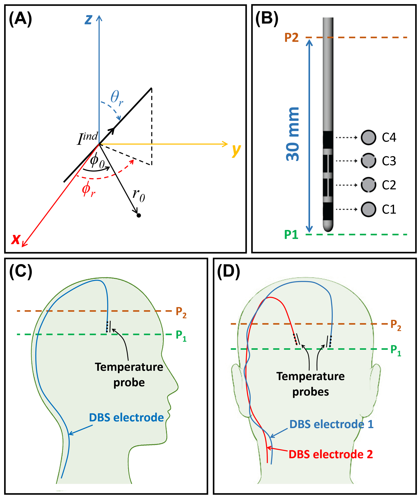
Depiction of the DBS electrode and its orientation in the experimental setup. (A) The coordinate parameters used in calculations of the field of the induced current on an oblique DBS electrode. (B) Depiction of the commercial segmented DBS electrode used throughout this study. (C) A sagittal depiction of the DBS electrode’s trajectory in the unilateral configuration. (D) A coronal depiction of the DBS electrodes’ trajectories in the bilateral configuration. DBS, Deep Brain Stimulation
On the one hand, the total induced current on the electrode due to an arbitrary excitation of the pTx RF coil, , can be expanded in the form of a superposition of induced currents due to single-channel excitations, as follows
| (3) |
where, denotes the complex weight of the transmit channel. Equation 3 can be written in the form of matrix-vector multiplication as follows
| (4) |
where is a row vector consisting of induced currents, , and is an column vector consisting of complex weights, .
On the other hand, previous studies [32, 33] show that the induced current on the shaft of an electrode (near the tip) reliably controls the temperature increase (ΔT) at the tip of the electrode. Therefore, any complex excitation vector, , that is orthogonal to the row vector sets Equation 4 to zero and causes no heating at the tip of the electrode. Such an excitation vector can be considered an IF excitation mode for the electrode under examination. In other words, the null space [33] of the row vector (i.e.,)—which is an matrix— provides all linearly independent IF modes of an -channel pTx coil for a particular electrode. Note that since the row vector is considered a rank-deficient matrix with the rank of 1, according to the rank-nullity theorem [34] (i.e., ), there exist linearly independent vectors, , that set Equation 4 to zero. These vectors, , are the columns of the matrix such that
| (5) |
3. METHODS
Here, we have proposed a workflow (Figure 2) for determining the IF excitation modes of an -channel pTx coil that can be used to safely image bilateral DBS electrodes at 7T. Nevertheless, this workflow can be simply extended to any number of DBS electrodes as long as the number of transmit channels is greater than the number of electrodes (i.e., due to the rank-nullity theorem [34]). The proposed workflow was experimentally validated using commercial DBS electrodes (directional lead, Infinity DBS system, Abbott Laboratories, Chicago, IL) placed unilaterally and bilaterally inside a uniform head-shaped gel phantom (14g/L Hydroxyethyl Cellulose, 2.25g/L NaCl, and 0.25g/L CuSO4 with electrical properties of and ). All experiments were carried out on a 7T whole-body MRI scanner (Magnetom, Siemens Healthineers, Erlangen, Germany) utilizing a 16-channel transmission line transceiver (TxRx) array RF coil [31]. Each channel of the RF coil was powered by a 1kW amplifier (Communication Power Corporation, Hauppauge, NY) controlled by a remotely operated 16-channel RF phase/amplitude gain unit.
Figure 2.
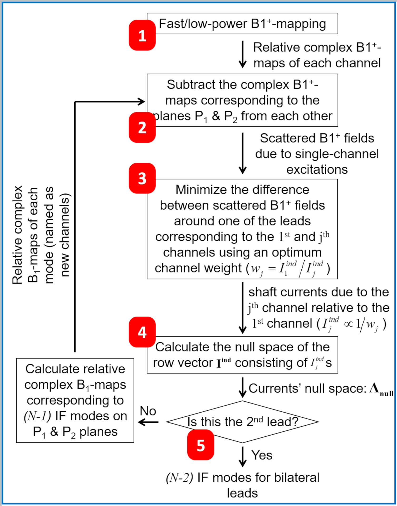
Workflow for calculating the implant-friendly excitation modes of an N-channel pTx coil for safe MRI of bilateral DBS electrodes. DBS, Deep Brain Stimulation
3.1. IF Mode Calculation Workflow
Figure 2 shows our previously proposed IF mode calculation workflow [35] extended from unilateral to bilateral electrode configuration. In the extended version, the IF modes for one of the electrodes were first calculated. Then, the latter modes were used in a similar process to calculate IF modes for the second electrode. Throughout this workflow, it was assumed that the incident (around the shaft on plane P2, where the current is measured) is approximately equal to the total underneath the tip of the electrode on plane P1 (Figures 1C and 1D) [32]. This approximation is based on the rationale that the electrode current has almost zero impact on the field at a plane located underneath the tip. The distance between the tip and shaft is short enough (~30mm) relative to the wavelength (~110–130mm) inside the human body (with relative permittivity in the range of 60–80) at 7T to assume a uniform incident field from the tip to the shaft. The proposed workflow (Figure 2) can be laid out in five steps, detailed as follows:
maps: First, complex relative maps corresponding to each Tx channel were acquired on two axial planes—one plane (P2) intersecting one of the electrodes at the shaft and the other plane (P1) underneath the tip of the same electrode (see Figures 1C and 1D)—using consecutive fast, low-flip-angle GRE sequences (see Section 3.2.1).
Scattered Fields: Assuming the incident field on Plane P2 and the total field on P1 are approximately equal [32], per-channel complex maps on plane P1 were subtracted from those on plane P2 to approximate the scattered fields, , on plane P2.
Relative Induced Currents: Governed by Equation 2, the induced current on the electrode’s shaft due to each Tx channel excitation, , is proportional to the scattered field on plane P2, , and was calculated relative to the induced current by channel 1, . For this purpose, minimization routines using MATLAB’s fminsearch function were performed on pairs of scattered fields (i.e., and ) to determine complex coefficients, , that minimize the difference between and pairs around the electrode’s shaft (i.e., within a 30×30mm2 square around the shaft).
Null Space of Induced Currents: After the relative induced currents () due to each of the transmit channels were calculated, the null space of the row vector was calculated to find all solutions that set Equation 4 to zero. The calculated null space, , contained column vectors, which were the IF excitation modes of the pTx coil under investigation for one of the DBS electrodes.
IF Modes: Considering this system utilized a bilateral DBS configuration, a similar routine was repeated for the second electrode with a modification in the definition of per-channel excitations. At the conclusion of the first routine (step 4), IF excitation modes were computed for the first electrode. In the subsequent procedure, these modes were employed as per-channel excitations for the second electrode. Eventually, () IF excitation modes were calculated, which set Equation 4 to zero at the shaft of both electrodes.
3.2. Experimental Validation
For both unilateral and bilateral electrode configurations, three types of experiments were conducted: 1) Acquisition of maps to calculate IF modes, 2) Validation of IF modes using temperature measurement, and 3) Evaluation of IF modes with RF shimming.
3.2.1. Maps: Per-Channel vs. IF Modes
As laid out in step 1 of the workflow above, complex maps on two axial planes P1 and P2 (Figures 1C and 1D) were acquired and post-processed to obtain the IF modes. For this purpose, a fast, low-power, relative mapping technique [36] was exploited. This technique consisted of 16 (number of pTx coil’s channel) consecutive small tip angle GRE scans with TR/TE=4500/1.52ms, flip-angle (FA)=5°, in-plane resolution=1mm, slice thickness=4mm, acquisition matrix=200×200, no. of averages=1, pixel bandwidth=735Hz/pixel, GRAPPA acceleration factor=2, and acquisition time=36s. During each scan, only a single Tx channel was active whereas the signal was received from all 16 receive channels [36].
The field generated by the induced RF current on the electrode interferes with the incident field generated by the Tx coil and causes an excessive inhomogeneity in the proximity of the electrode [33]. In theory, an IF mode excitation should be free of this effect since induced currents on the electrode are eliminated. To explore the efficacy of the IF mode calculations using this theory, maps corresponding to IF mode excitations on the axial plane P2 (see Figures 1C and 1D) were acquired and compared to maps corresponding to single-channel excitations on the same plane.
3.2.2. Temperature Measurement: IF Modes
To validate the calculated IF modes—which intended to eliminate the RF heating around the tip of the electrodes—the progression of temperature change at the tip of the DBS electrodes was measured while the experimental setup was exposed to RF energy using the pTx coil excited with an IF mode. The temperature measurement was performed using fiber optic temperature probes (Lumasense Technologies, Santa Clara, CA) and repeated for all calculated IF modes.
For the unilateral electrode experiment, a total average power of 6W was applied using a 1ms-square RF pulse with a duty cycle of 5%. Whereas, in the case of the bilateral electrodes, a 3D turbo-spin echo (TSE) sequence with FA=100°, TR/TE=300/105ms, in-plane resolution=0.35mm, slice thickness=1.25mm, acquisition matrix=576×576, TSE-factor 15, no. of averages=1, pixel bandwidth=225Hz/pixel was used, with a total average power of 12W.
To demonstrate the potential risks of DBS electrodes undergoing MRI scans, the unilateral electrode was exposed to RF energy using a 6W-square pulse with four different arbitrary excitations, and the ΔT was measured. For the same purpose, the worst-case heating scenario was tested by using the complex-conjugate of the relative per-channel induced currents as elements of the excitation vector. The ΔT at the tip of the electrode corresponding to this excitation was also measured. Similarly, in the bilateral electrode configuration, the worst-case heating scenarios for each electrode were calculated and utilized in the temperature measurement experiments (i.e, the 12W-TSE sequence).
3.2.3. RF Shimming: Conventional vs. IF Modes
To evaluate the capability of the IF modes in RF shimming applications, a clinically-relevant region-of-interest (i.e., representing an ROI in the frontal lobe) was chosen. RF shimming with the goal of minimum inhomogeneity within the ROI was performed using the calculated IF modes, as well as the scanner’s shimming toolbox. The IF modes shimming was performed by solving the following optimization problem utilizing MATLAB’s fminsearch function with the Nelder-Mead optimization algorithm:
| (6) |
where is an Npxl×N matrix whose columns consist of per-channel complex values on pixels within the ROI. is an vector (i.e., : number of electrodes) and represents complex weights of IF modes. ∥·∥ denotes the -norm of the vector it operates on. CoV is the coefficient of variation and defined as
| (7) |
In the case of the unilateral configuration, the calculated shim solutions were used to run a 2D-TSE sequence (FA=180°, TR/TE=3040/49ms, in-plane resolution=0.2mm, slice thickness=2mm, acquisition matrix=576×432, TSE-factor 11, no. of averages=1, pixel bandwidth=240Hz/pixel, with a total average power of 15W). Whereas for the bilateral configuration, the calculated shim solutions were used to run a 3D-TSE sequence (FA=100°, TR/TE=200/105ms, in-plane resolution=0.35mm, slice thickness=1.25mm, acquisition matrix=576×432, TSE-factor 15, no. of averages=1, pixel bandwidth=225Hz/pixel, with a total average power of 12W). In all cases, ΔT was measured. Also, to demonstrate the potential of the IF strategy in imaging the tissues around electrodes in DBS patients, inhomogeneity of the TSE images around electrodes (i.e., within a circle with a diameter of 30mm) on plane P2 was quantitatively compared using the CoV.
4. RESULTS
4.1. IF Modes
Figure 3 shows the amplitudes and phases of 15 excitation vectors—corresponding to the 16-channel pTx coil [31]—that produce IF modes for the unilateral electrode configuration. The green diamond on each plot corresponds to the predominant channel within that particular IF mode. Similarly, Figure 4 represents the 14 IF modes of this coil for the bilateral electrode configuration.
Figure 3.
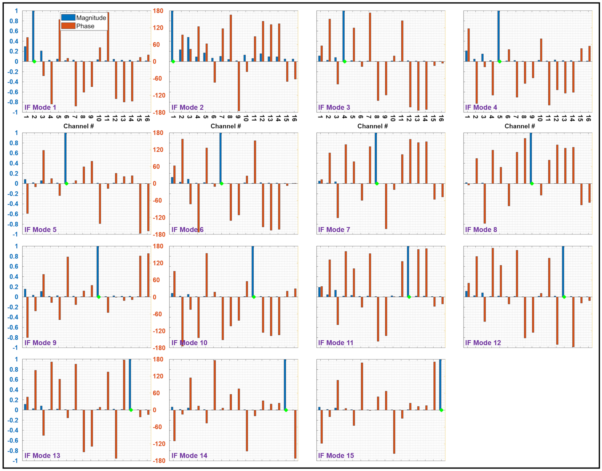
Amplitudes (blue bars) and phases (red bars) of 15 implant-friendly excitation vectors—corresponding to the 16-channel pTx coil—for the unilateral electrode configuration. The green diamond on each plot corresponds to the predominant channel within that particular IF mode. IF, implant-friendly
Figure 4.
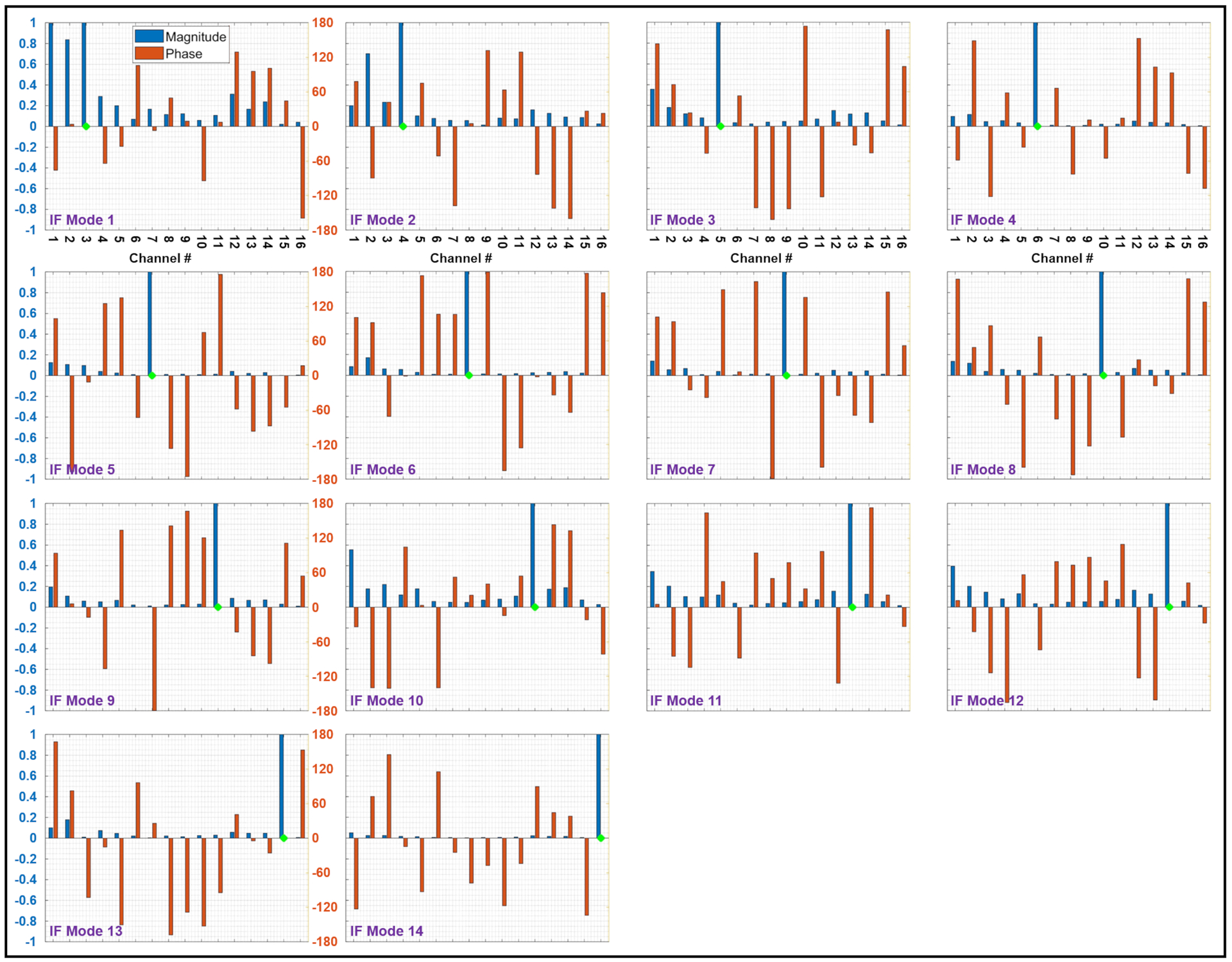
Amplitudes (blue bars) and phases (red bars) of 14 implant-friendly excitation vectors—corresponding to the 16-channel pTx coil—for the bilateral electrode configuration. The green diamond on each plot corresponds to the predominant channel within that particular IF mode. IF, implant-friendly
4.2. Experimental Validation
4.2.1. Maps: Per-Channel vs. IF Modes
Using the IF excitations above, a map corresponding to each mode was acquired on plane P2 and compared to that of the per-channel excitation. Figures 5 and 6 show the outcome of this comparative study for unilateral and bilateral electrode configurations, respectively.
Figure 5.
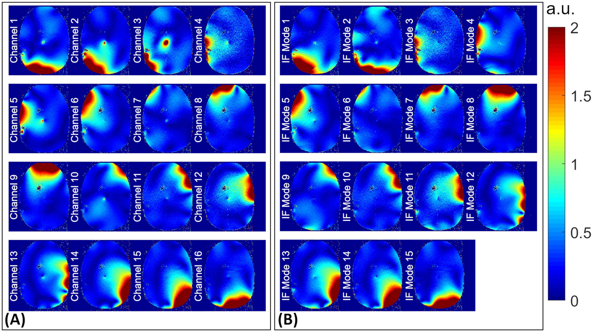
maps corresponding to (A) per-channel and (B) IF modes excitations experimentally acquired on plane P2 (see Figure 1) in the unilateral configuration. IF, implant-friendly
Figure 6.
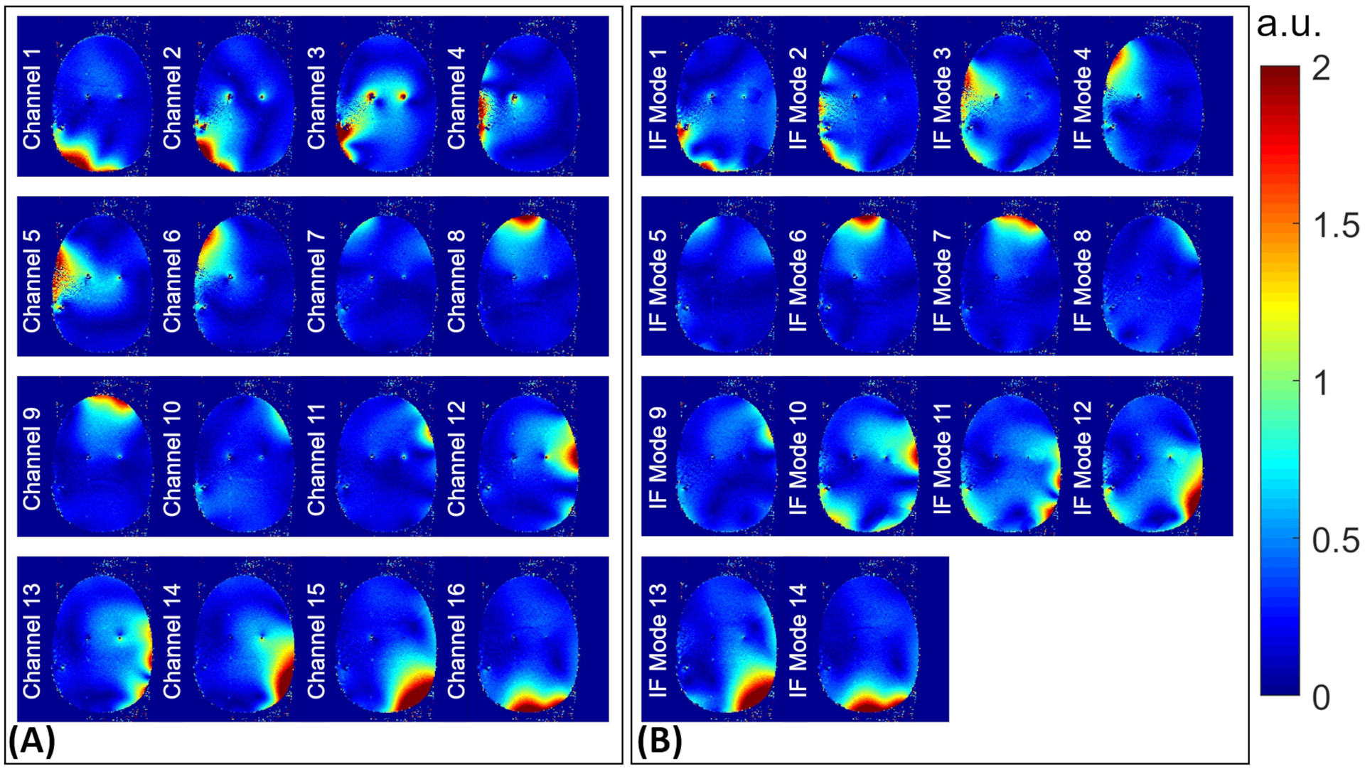
maps corresponding to (A) per-channel and (B) IF modes excitations experimentally acquired on plane P2 (see Figure 1) in the bilateral configuration. IF, implant-friendly
4.2.2. Temperature Measurement: IF Modes
Using a square RF pulse with a 6W total average power, the unilateral electrode setup was exposed to RF energy. The ΔT at the tip of the electrode was recorded for all 15 IF modes, as shown in Figure 7A. Whereas the bilateral electrode setup had undergone an MRI scan using a TSE pulse sequence with a total average power of 12W, and the ΔT at the tip of both electrodes corresponding to 14 IF excitation modes were measured and are presented in Figure 8A.
Figure 7.
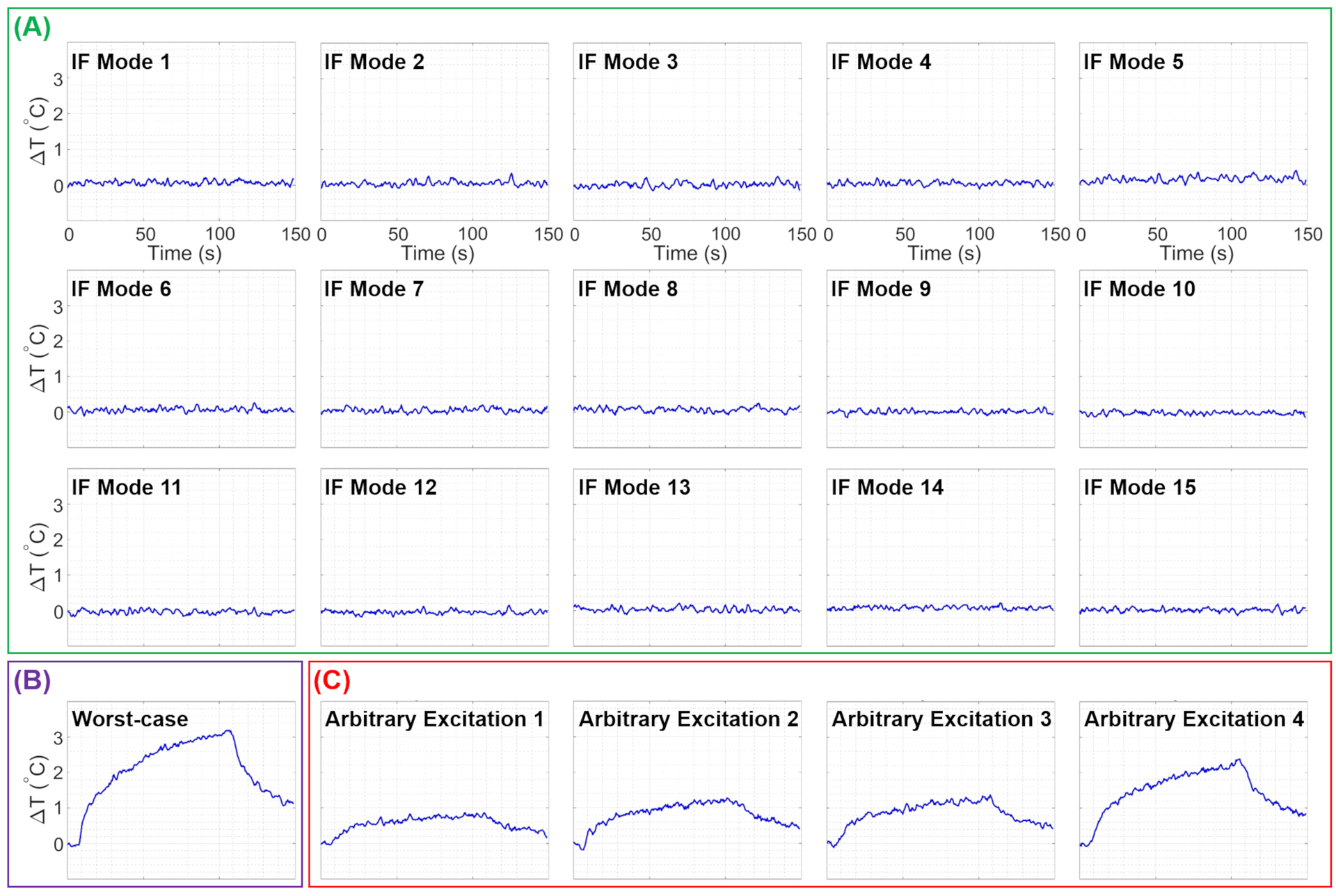
Experimentally measured temperature changes at the tip of the unilateral electrode due to RF exposures corresponding to the (A) IF modes, (B) worst-case heating, and (C) four arbitrary excitations. IF, implant-friendly
Figure 8.
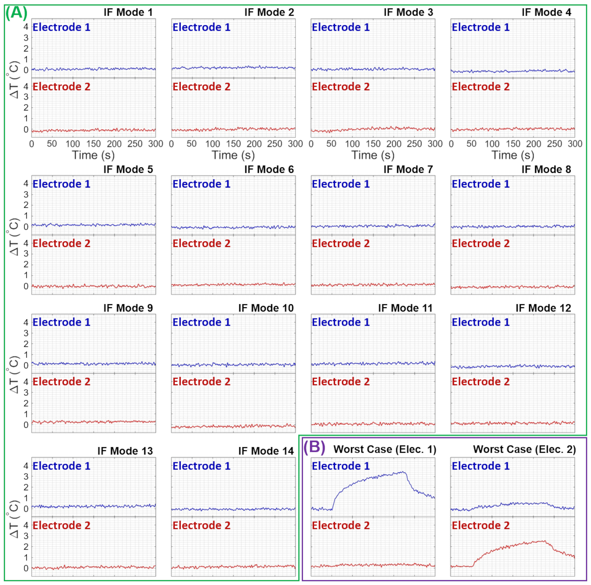
Experimentally measured temperature changes at the tips of the bilateral electrodes due to RF exposures corresponding to the (A) IF modes and (B) worst-case heating excitations for electrodes 1 and 2. IF, implant-friendly
Also, the ΔT was measured in the worst-case heating scenarios for both unilateral and bilateral configurations, and they are demonstrated in Figures 7B and 8B, respectively. Furthermore, Figure 7C shows the ΔT at the tip of the electrode in the unilateral configuration for four arbitrary excitation vectors.
4.2.3. RF Shimming: Conventional vs. IF Modes
For both unilateral and bilateral configurations, a rectangular ROI was chosen in the right anterior of the head-shaped phantom, as respectively indicated in Figures 9 and 10. Employing the calculated IF modes, as well as the scanner’s shimming toolbox, RF shimming was performed within the ROI. These RF shimming scenarios resulted in different excitation vectors, which were utilized for 2D- and 3D-TSE imaging of the unilateral and bilateral configuration, respectively. Figure 9 shows the TSE images, as well as the ΔT at the tip, corresponding to the unilateral electrode configuration for both shimming scenarios. While excitation using the scanner-calculated shimming solution caused a ΔT of ~2.6°C, the IF excitation did not cause any measurable ΔT at contacts of the electrode. Moreover, the CoV around the shaft of the electrode was calculated to be 49% and 31% for the scanner’s shimming solution and IF excitation, respectively.
Figure 9.
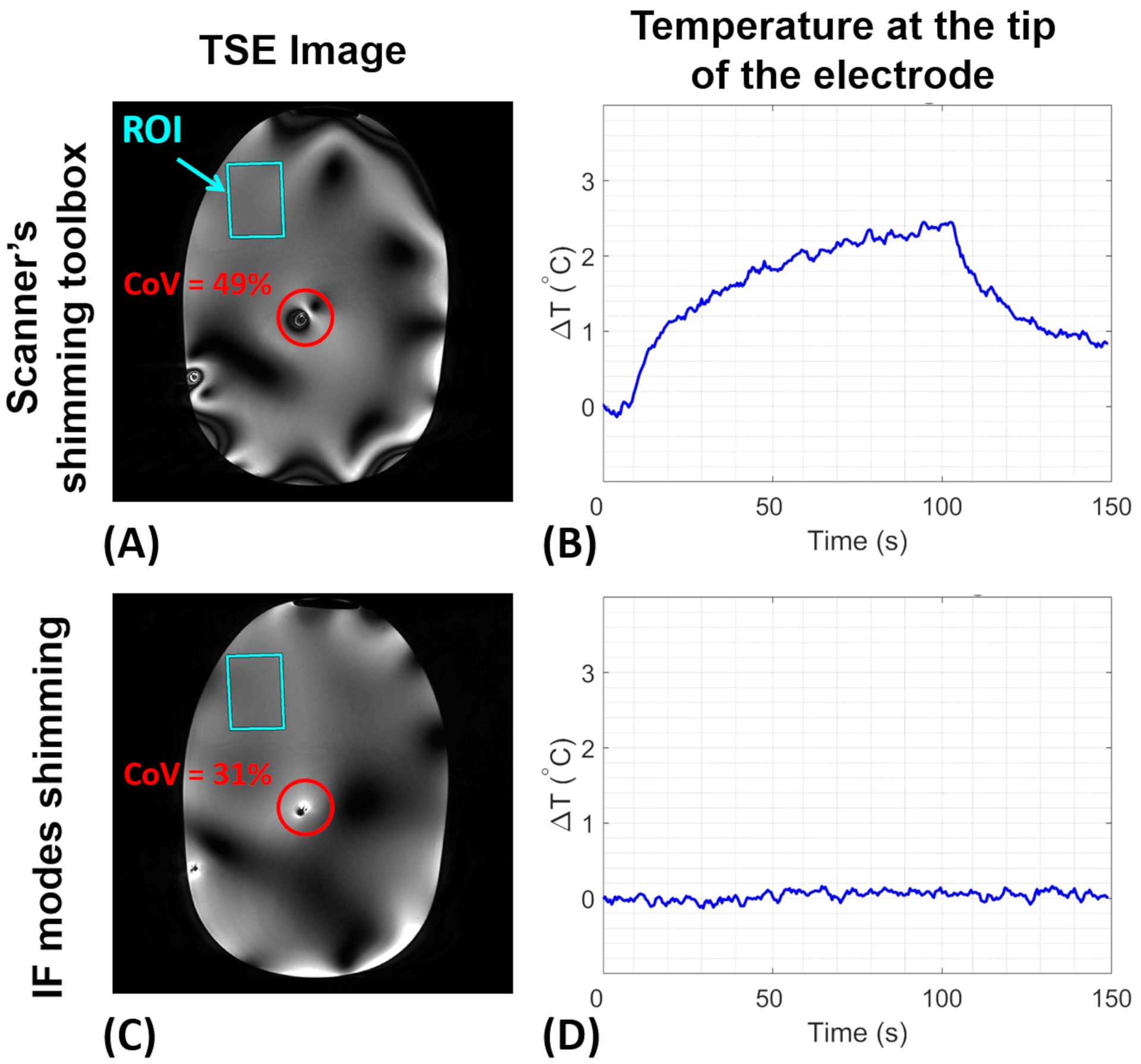
RF shimming within the indicated ROI using the scanner’s shimming toolbox vs. the IF modes for the unilateral configuration. (A-C) 2D-TSE images. The red circle shows the area around the electrode, whose CoV was chosen to evaluate image uniformity. (B-D) Experimentally measured temperature change at the tip of the electrode. TSE, turbo spin-echo; CoV, coefficient of variation
Figure 10.
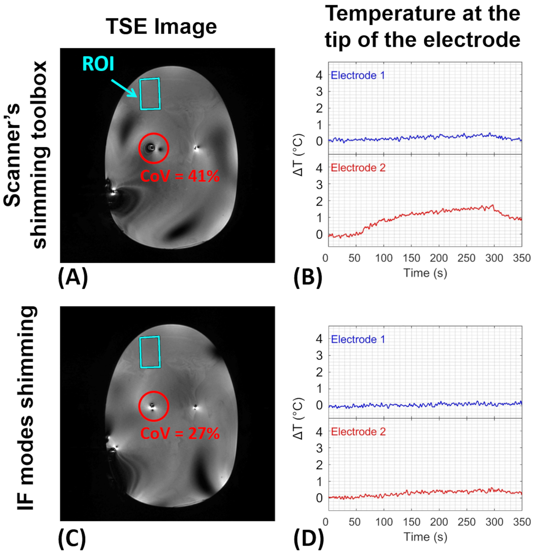
RF shimming within the indicated ROI using the scanner’s shimming toolbox vs. the IF modes for the bilateral configuration. (A-C) 3D-TSE images. The red circle shows the area around the electrode, whose CoV was chosen to evaluate image uniformity. (B-D) Experimentally measured temperature change at the tip of the electrodes. TSE, turbo spin-echo; CoV, coefficient of variation
Similarly, Figure 10 summarizes the results for the bilateral electrode configuration. In this case, the highest ΔT among two electrodes was measured as ~2°C and ~0.5°C for scanner-calculated and IF shimming scenarios, respectively. The CoV around the corresponding electrode in the two shimming scenarios was calculated as 41% and 27%, respectively.
5. DISCUSSION
In this study, a new strategy was proposed to calculate the implant-friendly modes of a pTx coil for unilateral and bilateral DBS electrode configurations. IF modes were intended to generate zero induced RF current on the electrodes at a particular distance from the tip, thereby minimizing DBS electrode heating. The proposed technique is based on well-known EM scattering, reciprocity [37], and superposition [38] theorems. Scattering and reciprocity theorems impose a condition that an induced current on a conductor (in this case, DBS electrode) generates an EM field, which is called a scattered field and is linearly proportional to the induced current’s as well as the source’s excitation. In addition, the superposition theorem implies that any incident and scattered EM fields caused by an array of sources (in this case, Tx array coil) can be expanded as a linear superposition of incident and scattered fields caused by individual sources. Employing these EM theorems in the DBS electrodes problem, the induced current on the electrode by individual pTx channels was related to scattered fields per individual channel. Then, all linearly independent excitation modes (i.e., IF modes) that generate zero total induced current on the electrode were determined by calculating the null space of the per-channel induced currents.
It is noteworthy that the proposed workflow takes advantage of pTx coils—which are mostly available at ultrahigh fields (defined as ≥7T) and continuously growing in number and variety [39–49]—to cancel out the net-induced RF currents on multiple DBS electrodes simultaneously. Theoretically, this approach is not limited to 7T and can be applied to any pTx coils at any field strength, including lower [39–41] and higher [42–49] field strengths. Yet, the implementation of this approach would not be possible utilizing commonly-used single-channel or even two-port-driven coils that are commercially available at lower field strengths (i.e., 1.5T and 3T). In other words, based on the rank-nullity theorem [34], to find a non-zero solution for Equation 4 with number of transmit channels, the necessary condition is (i.e., # of IF modes = ). Note that since the number of IF modes is always less than the number of independent excitation modes of the pTx coil (i.e., IF modes vs. independent modes), the proposed technique results in fewer degrees of freedom for shimming compared to non-IF shimming techniques. While this reduction in degrees of freedom may limit the shimming capability of a pTx coil in realistic imaging scenarios, it can be deemed an acceptable tradeoff to ensure the safety of DBS patients during MRI scans.
In the second step of the workflow, to calculate the scattered on an axial plane P2 retrospectively from the experimentally acquired total field on the same plane, the incident fields on plane P1 and P2 were assumed to be approximately equal. This approximation is based on the condition that the distance between planes P1 and P2 (~30mm) is short enough relative to the EM wavelengths inside the human body at 7T (~120mm). To verify this assumption, relative maps on two axial planes 30mm apart were acquired (i.e., planes P1 and P2) for 16 single-channel excitations inside the uniform head-shaped phantom without the DBS electrode. As shown in Supporting Information Figure S1, the normalized root-mean-square error (NRMSE) of maps within the indicated ROI is less than 9%. The indicated ROI represents the region around the electrodes’ shafts in the bilateral configuration. It should be noted that this assumption was only verified for the particular pTx coil [31] used in this study. Thus, a similar verification procedure must be performed if there are any changes in the field strength and/or pTx coil. In a similar manner, the validity of this assumption in a human head imaging scenario was evaluated by in vivo mapping on axial planes P1 and P2 (i.e., 30mm apart). The corresponding results with a median NRMSE of 11% are presented in Supporting Information Figure S2.
In support of the hypothesis that an IF mode should be free of scattered fields, Figures 5 and 6 show that the total fields corresponding to IF modes form relatively uniform maps around the electrode, whereas some of the single-channel excitations present excessive anomalies around the electrode (e.g., channels 1,2,3,5 in Figure 5 and channels 2,3,4 in Figure 6). These anomalies are the consequence of complex interferences between the incident fields and scattered fields caused by induced currents on the electrode. Nevertheless, not every single-channel excitation induces a significant current on the electrode—causing a recognizable anomaly around the electrode. Such a single-channel excitation—which interacts with the electrodes negligibly—along with minimal contributions from other channels, is likely to form one of the IF modes. For example, channel 9 in Figure 5A does not cause an anomaly around the electrode and has almost an identical profile as IF Mode 8 in Figure 5B. This is also reflected in the excitation vector of IF Mode 8 shown in Figure 3, where channel 9 (the predominant channel indicated by the green diamond) is almost the only contributing channel to the excitation vector. A similar example in the bilateral configuration is channel 16 in Figure 6A and IF Mode 14 in Figure 6B. The excitation vector corresponding to IF mode 14, shown in Figure 4, supports the idea that channel 16, with minimal contributions from other channels, can serve as an IF excitation mode.
The efficacy of the IF mode calculations was further assessed by monitoring the temperature change at the tip of the electrodes while the setup was exposed to RF energy with IF excitation modes. As shown in Figures 7 and 8, no heating at a level measurable with our temperature probes was detected. Furthermore, for both unilateral and bilateral configurations, the worst-case heating scenarios (Figures 7B and 8B) were calculated and utilized in heating experiments as demonstrations of potential risks of DBS electrodes undergoing MRI scans. In the worst-case scenario, the temperature at the tip of the unilateral electrode was increased up to 3.5°C for a 6W RF exposure. Similarly, the worst-case scenario for the bilateral configuration caused 3.5°C and 2.5°C temperature increases, respectively, in electrode 1 and electrode 2 for a 12W RF exposure. Since the worst-case heating scenarios were deliberately calculated, the likelihood of occurrence of such excitations in a clinical scan can be argued. To elaborate on such an argument and to further emphasize the significance of the IF excitation strategies, four arbitrary excitations with a 6W input power were applied to the unilateral configuration, and ΔT from ~1°C to 2.5°C were recorded (see Figure 7C). To further investigate the importance of IF excitations, some risks and drawbacks of non-IF excitations were evaluated in a bilateral electrode setup (Supporting Information Figure S3). In the corresponding experiment, 3D-TSE imaging was performed using a circularly-polarized (CP) excitation with a total average power of 12W. Although the temperature increase at electrodes was negligible, the imaging artifact around electrode 2 (left electrode) was considerably high. Moreover, the temperature at the tip of electrodes corresponding to some of the per-channel excitations was measured. As a result of this measurement, temperature increases were observed in some cases (e.g., channels 14 and 15), implying a potential risk of non-IF excitations.
To attain a complete picture of the heating propensity of the DBS electrode with the pTx coil under investigation, a Monte-Carlo simulation with 107 random excitation vectors was performed, and corresponding ΔT at the tip of electrode 1 in the bilateral configuration (see Figure 1D) was recorded and presented as a histogram in Supporting Information Figure S4. To perform the Monte-Carlo simulation, the induced current on the DBS electrode, (see Equation 4), corresponding to each random excitation vector, was calculated and normalized to that of the worst-case scenario. The square of the normalized induced current was used to scale the worst-case ΔT (Figure 8B) and calculate the corresponding ΔT. While the worst-case excitation heats up the electrode by 3.5°C, the temperature increase remains below 2°C in 99% of cases, for this particular trajectory.
To prove the concept of IF modes and to demonstrate the use of IF modes in RF shimming scenarios, a simple shimming scenario with the objective of a uniform FA within an ROI was investigated where a rectangular ROI in the right anterior of the phantom was chosen, representing an ROI in a brain’s frontal lobe. This shimming scenario was carried out using IF modes as well as the scanner’s shimming toolbox. While the former uses the IF excitation modes as the basis of the excitation space, the latter uses individual-channel excitations for the shimming problem. As shown in Figure 9 for the unilateral configuration, the IF mode solution did not result in any measurable heating for a 3D-TSE sequence, whereas the scanner’s shim solution caused ~2.5°C temperature increase for the same pulse sequence parameters. The induced current mitigation also improved image quality in the vicinity of the electrode. In the case of the scanner’s shimming toolbox (Figure 9A), the induced current on the electrode generated scattered field in close proximity to the electrode. Complex interference of the scattered and incident fields caused overflips and underflips around the electrode, which resulted in significant inhomogeneity in the TSE image around the electrode. Whereas the IF solution (Figure 9C) was free of the induced current and hence resulted in more homogeneous image intensity.
Similarly, in the case of the bilateral configuration (see Figure 10), both the scanner’s shimming toolbox and IF modes were employed to calculate the homogeneous excitation within the rectangular ROI in the right anterior of the phantom. Using the scanner’s shim solution, while electrode 1 was heated negligibly (~0.5°C), electrode 2 experienced significant heating for a tissue as sensitive as the brain (~2°C). It is noteworthy that in this configuration, the IF shim solution did not entirely eliminate the induced current for electrode 2, and the residual induced current caused minor heating (~0.5°C). This can be justified by taking into account the fact that induced currents on electrodes in the bilateral configuration interact with each other, which could be considered in Equation 1 by adding a second term as follows
| (8) |
The second term in Equation 8 represents the scattered field by Electrode 2 around the shaft of Electrode 1. Since the scattered field decays with 1/r (distance from the electrode), the first term is considerably more dominant around Electrode 1 compared to the second term, and vice versa. Thus, the second term in Equation 8 was neglected for the simplicity of calculation.
In the proposed technique, correctly determining the location of plane P2 (at the electrode’s shaft) is essential. On the one hand, since susceptibility artifacts are extremely high around the metallic contacts of the electrode and disrupt the mapping close to the contacts, plane P2 should intersect the electrode at a location sufficiently far from the metallic contacts. On the other hand, the assumption of equal incident fields on planes P1 (underneath the electrode’s tip) and P2 (at the electrode’s shaft) only holds if the distance between them is short enough relative to the EM wavelength. Therefore, plane P2 should be positioned close to the electrode’s tip. These opposing conditions result in a narrow range of possible locations for plane P2. In the case of the commercial electrode utilized throughout this work, the optimal location on the electrode’s shaft for plane P2 was determined to be 30mm away from the electrode’s tip.
In this study, experimental validations for IF modes calculation workflow were performed in a uniform phantom. However, heterogeneity of the human head may increase the nonuniformity of fields (as shown in Supporting Information Figure S2), as well as susceptibility artifacts around the electrode. Both factors can degrade the efficacy of the proposed IF mode calculation workflow. In this regard, further investigations in heterogeneous media, such as animal specimens, are required.
6. CONCLUSIONS
In this study, a systematic workflow was proposed to determine the implant-friendly RF excitation modes of a pTx coil for unilateral and bilateral electrode configurations undergoing an MRI scan at 7T. The proposed workflow was experimentally tested and validated by means of mapping and temperature monitoring around commercial DBS electrodes. None of the calculated IF excitation modes caused a measurable temperature increase at the tip of the electrodes. The IF modes were also employed to obtain an RF shim solution within a predetermined ROI. Using clinically-relevant 2D- and 3D-TSE pulse sequences, corresponding solutions were compared with those of the scanner’s shimming toolbox. Findings suggested that while the outcome of the scanner’s shimming toolbox can cause excessive heating in electrodes, the IF shim solution does not heat up the electrode. Hence, the proposed workflow can determine implant-friendly excitations to safely scan DBS patients.
Supplementary Material
Supporting Information Figure S1. Verification of the assumption that the incident fields on planes P1 and P2 (see Figure 1) around the electrodes are equal with a negligible error. This relative -mapping experiment was conducted inside the head-shaped uniform phantom while the DBS electrodes were absent. (A) A depiction of planes P1 and P2 with respect to the head phantom. (B) Experimentally acquired maps on planes P1 and P2 corresponding to single-channel excitations. The ROI shown as red rectangular represents the region where the shaft of electrodes was located in the bilateral configuration. The alteration of the incident fields within the ROI between two planes is quantified using normalized root-mean-square error (NRMSE). (C) A boxplot representation of the NRMSE values throughout different single-channel excitations. Although the maximum NRMSE is almost 9%, the median of NRMSEs is only 4%.
Supporting Information Figure S2. Verification of the assumption that the incident fields on planes P1 and P2 (see Figure 1) around the electrodes are equal with a negligible error. This relative -mapping experiment was conducted in vivo in a healthy human subject head (without DBS electrodes). (A) A depiction of planes P1 and P2 with respect to the head. (B) Experimentally acquired maps on planes P1 and P2 corresponding to single-channel excitations. The ROI shown as red rectangular represents the region where the shaft of electrodes would be located in a hypothetical bilateral DBS configuration. The alteration of the incident fields within the ROI between two planes was quantified using normalized root-mean-square error (NRMSE). (C) A boxplot representation of the NRMSE values throughout different single-channel excitations. Although the maximum NRMSE is 20% (corresponding to Channel 8 excitation), the median of NRMSEs is 11%.
Supporting Information Figure S3. Evaluation of temperature increase in CP mode and per-channel excitations, as well as the image quality of the CP excitation. In all cases, a 3D-TSE sequence (FA=100°, TR/TE=200/105ms, in-plane resolution=0.35mm, slice thickness=1.25mm, acquisition matrix=576×432, TSE-factor 15, no. of averages=1, pixel bandwidth=225Hz/pixel, with a total average power of 12W) was used for imaging. (A) A depiction of the bilateral DBS electrode setup inside a uniform phantom with a contralateral configuration. (B) Imaging with the CP mode of excitation: An axial slice of the TSE image (on plane P2) and corresponding temperature increase at the tip of electrodes. (C) The temperature increase due to some of the per-channel excitations. CP, Circularly-polarized
Supporting Information Figure S4. Histogram of the temperature increase at the tip of a DBS electrode corresponding to 107 random RF excitation vectors (i.e., with the 16-channel pTx coil [31]). To attain this histogram, a Monte-Carlo simulation was performed, whereby the induced current on the DBS electrode, (see Equation 4)—corresponding to each random excitation vector—was calculated and normalized to that of the worst-case scenario. The square of the normalized induced current was used to scale the worst-case ΔT (Figure 8B) and calculate the corresponding ΔT. While the worst-case excitation heats up the electrode by 3.5°C, the temperature increase remains below 2°C in 99% of cases. It is noteworthy that this simulation was performed for the DBS electrode 1 depicted in Figure 1D and may result in different outcomes for different DBS configurations/trajectories.
Acknowledgment
This work was supported by the following grant: NIBIB P41 EB027061, NINDS R01NS115180. The DBS electrodes were donated by Abbott Neuromodulation. The authors would like to thank Mr. Matt Waks for their help in editing this manuscript.
Data Availability Statement
The code that supports the findings of this study is openly available at https://github.com/AliSaMRI/DBS_IF_Mode_Calculator.
References
- 1.Limousin P, Pollak P, Benazzouz A, et al. Effect on parkinsonian signs and symptoms of bilateral subthalamic nucleus stimulation. The Lancet 1995;345(8942):91–95. [DOI] [PubMed] [Google Scholar]
- 2.Krack P, Batir A, Van Blercom N, et al. Five-year follow-up of bilateral stimulation of the subthalamic nucleus in advanced Parkinson’s disease. New England Journal of Medicine 2003;349(20):1925–34. [DOI] [PubMed] [Google Scholar]
- 3.Benabid AL, Pollak P, Gao D, et al. Chronic electrical stimulation of the ventralis intermedius nucleus of the thalamus as a treatment of movement disorders. Journal of neurosurgery 1996;84(2):203–14. [DOI] [PubMed] [Google Scholar]
- 4.Deep-Brain Stimulation for Parkinson’s Disease Study Group. Deep-brain stimulation of the subthalamic nucleus or the pars interna of the globus pallidus in Parkinson’s disease. New England Journal of Medicine 2001;345(13):956–63. [DOI] [PubMed] [Google Scholar]
- 5.Herrington TM, Cheng JJ, Eskandar EN. Mechanisms of deep brain stimulation. Journal of neurophysiology 2016;115(1):19–38. [DOI] [PMC free article] [PubMed] [Google Scholar]
- 6.Starr PA, Turner RS, Rau G, et al. Microelectrode-guided implantation of deep brain stimulators into the globus pallidus internus for dystonia: techniques, electrode locations, and outcomes. Journal of neurosurgery 2006;104(4):488–501. [DOI] [PubMed] [Google Scholar]
- 7.International Electrotechnical Commission. Medical electrical equipment-Part 2–33: Particular requirements for the basic safety and essential performance of magnetic resonance equipment for medical diagnosis. IEC 60601–2-33 Ed. 4.0. 2022.
- 8.Henderson JM, Tkach J, Phillips M, Baker K, Shellock FG, Rezai AR. Permanent neurological deficit related to magnetic resonance imaging in a patient with implanted deep brain stimulation electrodes for Parkinson’s disease: case report. Neurosurgery 2005;57(5):E1063–E63. [DOI] [PubMed] [Google Scholar]
- 9.Erhardt JB, Fuhrer E, Gruschke OG, et al. Should patients with brain implants undergo MRI. Journal of neural engineering 2018;15(4):041002. [DOI] [PubMed] [Google Scholar]
- 10.Golestanirad L, Angelone LM, Iacono MI, Katnani H, Wald LL, Bonmassar G. Local SAR near deep brain stimulation (DBS) electrodes at 64 and 127 MH z: A simulation study of the effect of extracranial loops. Magnetic resonance in medicine. 2017. Oct;78(4):1558–65. [DOI] [PMC free article] [PubMed] [Google Scholar]
- 11.Bhusal B, Keil B, Rosenow J, Kazemivalipour E, Golestanirad L. Patient’s body composition can significantly affect RF power deposition in the tissue around DBS implants: ramifications for lead management strategies and MRI field-shaping techniques. Physics in Medicine & Biology. 2021. Jan 13;66(1):015008. [DOI] [PMC free article] [PubMed] [Google Scholar]
- 12.Bhusal B, Nguyen BT, Sanpitak PP, Vu J, Elahi B, Rosenow J, Nolt MJ, Lopez‐Rosado R, Pilitsis J, DiMarzio M, Golestanirad L. Effect of device configuration and patient’s body composition on the RF heating and nonsusceptibility artifact of deep brain stimulation implants during MRI at 1.5 T and 3T. Journal of Magnetic Resonance Imaging. 2021. Feb;53(2):599–610. [DOI] [PubMed] [Google Scholar]
- 13.Shrivastava D, Abosch A, Hanson T, Tian J, Gupte A, Iaizzo PA, Vaughan JT. Effect of the extracranial deep brain stimulation lead on radiofrequency heating at 9.4 Tesla (400.2 MHz). Journal of magnetic resonance imaging. 2010. Sep;32(3):600–7. [DOI] [PMC free article] [PubMed] [Google Scholar]
- 14.Yeung CJ, Susil RC, Atalar E. RF safety of wires in interventional MRI: using a safety index. Magnetic Resonance in Medicine: An Official Journal of the International Society for Magnetic Resonance in Medicine. 2002. Jan;47(1):187–93. [DOI] [PubMed] [Google Scholar]
- 15.Guerin B, Iacono MI, Davids M, Dougherty D, Angelone LM, Wald LL. The ‘virtual DBS population’: five realistic computational models of deep brain stimulation patients for electromagnetic MR safety studies. Physics in Medicine & Biology. 2019. Feb 4;64(3):035021. [DOI] [PMC free article] [PubMed] [Google Scholar]
- 16.Guerin B, Serano P, Iacono MI, Herrington TM, Widge AS, Dougherty DD, Bonmassar G, Angelone LM, Wald LL. Realistic modeling of deep brain stimulation implants for electromagnetic MRI safety studies. Physics in Medicine & Biology. 2018. May 4;63(9):095015. [DOI] [PMC free article] [PubMed] [Google Scholar]
- 17.Eryaman Y, Akin B, Atalar E. Reduction of implant RF heating through modification of transmit coil electric field. Magnetic resonance in medicine. 2011. May;65(5):1305–13. [DOI] [PubMed] [Google Scholar]
- 18.Eryaman Y, Turk EA, Oto C, Algin O, Atalar E. Reduction of the radiofrequency heating of metallic devices using a dual‐drive birdcage coil. Magnetic resonance in medicine. 2013. Mar 1;69(3):845–52. [DOI] [PubMed] [Google Scholar]
- 19.Golestanirad L, Keil B, Angelone LM, Bonmassar G, Mareyam A, Wald LL. Feasibility of using linearly polarized rotating birdcage transmitters and close‐fitting receive arrays in MRI to reduce SAR in the vicinity of deep brain simulation implants. Magnetic resonance in medicine. 2017. Apr;77(4):1701–12. [DOI] [PMC free article] [PubMed] [Google Scholar]
- 20.Kazemivalipour E, Keil B, Vali A, Rajan S, Elahi B, Atalar E, Wald LL, Rosenow J, Pilitsis J, Golestanirad L. Reconfigurable MRI technology for low-SAR imaging of deep brain stimulation at 3T: Application in bilateral leads, fully-implanted systems, and surgically modified lead trajectories. NeuroImage. 2019. Oct 1;199:18–29. [DOI] [PMC free article] [PubMed] [Google Scholar]
- 21.Eryaman Y, Guerin B, Akgun C, Herraiz JL, Martin A, Torrado‐Carvajal A, Malpica N, Hernandez‐Tamames JA, Schiavi E, Adalsteinsson E, Wald LL. Parallel transmit pulse design for patients with deep brain stimulation implants. Magnetic resonance in medicine. 2015. May;73(5):1896–903. [DOI] [PMC free article] [PubMed] [Google Scholar]
- 22.Guerin B, Angelone LM, Dougherty D, Wald LL. Parallel transmission to reduce absorbed power around deep brain stimulation devices in MRI: Impact of number and arrangement of transmit channels. Magnetic resonance in medicine. 2020. Jan;83(1):299–311. [DOI] [PMC free article] [PubMed] [Google Scholar]
- 23.Winter L, Silemek B, Petzold J, Pfeiffer H, Hoffmann W, Seifert F, Ittermann B. Parallel transmission medical implant safety testbed: Real‐time mitigation of RF induced tip heating using time‐domain E‐field sensors. Magnetic Resonance in Medicine. 2020. Dec;84(6):3468–84. [DOI] [PubMed] [Google Scholar]
- 24.Etezadi‐Amoli M, Stang P, Kerr A, Pauly J, Scott G. Controlling radiofrequency‐induced currents in guidewires using parallel transmit. Magnetic resonance in medicine. 2015. Dec;74(6):1790–802. [DOI] [PMC free article] [PubMed] [Google Scholar]
- 25.McElcheran CE, Yang B, Anderson KJ, Golenstani-Rad L, Graham SJ. Investigation of parallel radiofrequency transmission for the reduction of heating in long conductive leads in 3 Tesla magnetic resonance imaging. PLoS One. 2015. Aug 3;10(8):e0134379. [DOI] [PMC free article] [PubMed] [Google Scholar]
- 26.Duchin Y, Shamir RR, Patriat R, Kim J, Vitek JL, Sapiro G, Harel N. Patient-specific anatomical model for deep brain stimulation based on 7 Tesla MRI. PloS one. 2018. Aug 22;13(8):e0201469. [DOI] [PMC free article] [PubMed] [Google Scholar]
- 27.Schrock LE, Patriat R, Goftari M, Kim J, Johnson MD, Harel N, Vitek JL. 7T MRI and computational modeling supports a critical role of lead location in determining outcomes for deep brain stimulation: a case report. Frontiers in Human Neuroscience. 2021. Feb 11;15:631778. [DOI] [PMC free article] [PubMed] [Google Scholar]
- 28.Kazemivalipour E, Sadeghi-Tarakameh A, Keil B, Eryaman Y, Atalar E, Golestanirad L. Effect of field strength on RF power deposition near conductive leads: A simulation study of SAR in DBS lead models during MRI at 1.5 T—10.5 T. PloS one. 2023. Jan 26;18(1):e0280655. [DOI] [PMC free article] [PubMed] [Google Scholar]
- 29. https://www.siemens-healthineers.com/en-us/news/magnetomterrafdaclearance.html.
- 30. https://www.ge.com/news/press-releases/bringing-ultra-high-field-mr-imaging-from-research-to-clinical-signa-70t-fda-cleared.
- 31.Adriany G, Van de Moortele PF, Ritter J, Moeller S, Auerbach EJ, Akgün C, Snyder CJ, Vaughan T, Uğurbil K. A geometrically adjustable 16‐channel transmit/receive transmission line array for improved RF efficiency and parallel imaging performance at 7 Tesla. Magnetic Resonance in Medicine: An Official Journal of the International Society for Magnetic Resonance in Medicine. 2008. Mar;59(3):590–7. [DOI] [PubMed] [Google Scholar]
- 32.Sadeghi‐Tarakameh A, Zulkarnain NIH, He X, Atalar E, Harel N, Eryaman Y. A workflow for predicting temperature increase at the electrical contacts of deep brain stimulation electrodes undergoing MRI. Magnetic resonance in medicine. 2022. Nov;88(5):2311–25. [DOI] [PMC free article] [PubMed] [Google Scholar]
- 33.Eryaman Y, Kobayashi N, Moen S, Aman J, Grant A, Vaughan JT, Molnar G, Park MC, Vitek J, Adriany G, Ugurbil K. A simple geometric analysis method for measuring and mitigating RF induced currents on Deep Brain Stimulation leads by multichannel transmission/reception. Neuroimage. 2019. Jan 1;184:658–68. [DOI] [PMC free article] [PubMed] [Google Scholar]
- 34.Strang G Linear algebra and its applications. Belmont, CA: Thomson, Brooks/Cole; 2006. [Google Scholar]
- 35.Sadeghi-Tarakameh A, DelaBarre L, Zulkarnain NIH, Harel N, Eryaman Y. Implant-Friendly Excitation Strategies for Imaging DBS Electrodes at 7T. In Proceedings of the 29th Annual Meeting of ISMRM, 2021. p. 0414. [Google Scholar]
- 36.Van de Moortele PF, Ugurbil K. Very fast multi channel B1 calibration at high field in the small flip angle regime. InProc Intl Soc Mag Reson Med 2009. Apr 18 (Vol. 17, p. 367). [Google Scholar]
- 37.Balanis CA. Advanced engineering electromagnetics. John Wiley & Sons; 2012. Jan 24. [Google Scholar]
- 38.Balanis CA. Antenna theory: analysis and design. John wiley & sons; 2015. Dec 28. [Google Scholar]
- 39.Alagappan V, Nistler J, Adalsteinsson E, Setsompop K, Fontius U, Zelinski A, Vester M, Wiggins GC, Hebrank F, Renz W, Schmitt F. Degenerate mode band‐pass birdcage coil for accelerated parallel excitation. Magnetic Resonance in Medicine: An Official Journal of the International Society for Magnetic Resonance in Medicine. 2007. Jun;57(6):1148–58. [DOI] [PubMed] [Google Scholar]
- 40.Sadeghi-Tarakameh A, Kazemivalipour E, Gundogdu U, Erdogan S, Atalar E. Accelerating the co-simulation method for the design of transmit array coils for MRI. Magnetic Resonance Materials in Physics, Biology and Medicine. 2021. Feb;34:165–78. [DOI] [PubMed] [Google Scholar]
- 41.Kazemivalipour E, Sadeghi‐Tarakameh A, Atalar E. Eigenmode analysis of the scattering matrix for the design of MRI transmit array coils. Magnetic Resonance in Medicine. 2021. Mar;85(3):1727–41. [DOI] [PubMed] [Google Scholar]
- 42.Adriany G, Auerbach EJ, Snyder CJ, Gözübüyük A, Moeller S, Ritter J, Van de Moortele PF, Vaughan T, Uğurbil K. A 32‐channel lattice transmission line array for parallel transmit and receive MRI at 7 tesla. Magnetic Resonance in Medicine: An Official Journal of the International Society for Magnetic Resonance in Medicine. 2010. Jun;63(6):1478–85. [DOI] [PMC free article] [PubMed] [Google Scholar]
- 43.Raaijmakers AJ, Italiaander M, Voogt IJ, Luijten PR, Hoogduin JM, Klomp DW, van den Berg CA. The fractionated dipole antenna: A new antenna for body imaging at 7 T esla. Magnetic resonance in medicine. 2016. Mar;75(3):1366–74. [DOI] [PubMed] [Google Scholar]
- 44.Oezerdem C, Winter L, Graessl A, Paul K, Els A, Weinberger O, Rieger J, Kuehne A, Dieringer M, Hezel F, Voit D. 16‐channel bow tie antenna transceiver array for cardiac MR at 7.0 tesla. Magnetic resonance in medicine. 2016. Jun;75(6):2553–65. [DOI] [PubMed] [Google Scholar]
- 45.Shajan G, Kozlov M, Hoffmann J, Turner R, Scheffler K, Pohmann R. A 16‐channel dual‐row transmit array in combination with a 31‐element receive array for human brain imaging at 9.4 T. Magnetic resonance in medicine. 2014. Feb;71(2):870–9. [DOI] [PubMed] [Google Scholar]
- 46.Avdievich NI, Giapitzakis IA, Pfrommer A, Borbath T, Henning A. Combination of surface and ‘vertical’loop elements improves receive performance of a human head transceiver array at 9.4 T. NMR in Biomedicine. 2018. Feb;31(2):e3878. [DOI] [PubMed] [Google Scholar]
- 47.Sadeghi‐Tarakameh A, DelaBarre L, Lagore RL, Torrado‐Carvajal A, Wu X, Grant A, Adriany G, Metzger GJ, Van de Moortele PF, Ugurbil K, Atalar E. In vivo human head MRI at 10.5 T: A radiofrequency safety study and preliminary imaging results. Magnetic resonance in medicine. 2020. Jul;84(1):484–96. [DOI] [PMC free article] [PubMed] [Google Scholar]
- 48.Woo MK, DelaBarre L, Lee BY, Waks M, Lagore RL, Radder JW, Eryaman Y, Ugurbil K, Adriany G. Evaluation of a 16-channel transceiver loop+ dipole antenna array for human head imaging at 10.5 tesla. IEEE Access. 2020. Nov 6;8:203555–63. [DOI] [PMC free article] [PubMed] [Google Scholar]
- 49.Sadeghi‐Tarakameh A, Jungst S, Lanagan M, DelaBarre L, Wu X, Adriany G, Metzger GJ, Van de Moortele PF, Ugurbil K, Atalar E, Eryaman Y. A nine‐channel transmit/receive array for spine imaging at 10.5 T: Introduction to a nonuniform dielectric substrate antenna. Magnetic resonance in medicine. 2022. Apr;87(4):2074–88. [DOI] [PMC free article] [PubMed] [Google Scholar]
Associated Data
This section collects any data citations, data availability statements, or supplementary materials included in this article.
Supplementary Materials
Supporting Information Figure S1. Verification of the assumption that the incident fields on planes P1 and P2 (see Figure 1) around the electrodes are equal with a negligible error. This relative -mapping experiment was conducted inside the head-shaped uniform phantom while the DBS electrodes were absent. (A) A depiction of planes P1 and P2 with respect to the head phantom. (B) Experimentally acquired maps on planes P1 and P2 corresponding to single-channel excitations. The ROI shown as red rectangular represents the region where the shaft of electrodes was located in the bilateral configuration. The alteration of the incident fields within the ROI between two planes is quantified using normalized root-mean-square error (NRMSE). (C) A boxplot representation of the NRMSE values throughout different single-channel excitations. Although the maximum NRMSE is almost 9%, the median of NRMSEs is only 4%.
Supporting Information Figure S2. Verification of the assumption that the incident fields on planes P1 and P2 (see Figure 1) around the electrodes are equal with a negligible error. This relative -mapping experiment was conducted in vivo in a healthy human subject head (without DBS electrodes). (A) A depiction of planes P1 and P2 with respect to the head. (B) Experimentally acquired maps on planes P1 and P2 corresponding to single-channel excitations. The ROI shown as red rectangular represents the region where the shaft of electrodes would be located in a hypothetical bilateral DBS configuration. The alteration of the incident fields within the ROI between two planes was quantified using normalized root-mean-square error (NRMSE). (C) A boxplot representation of the NRMSE values throughout different single-channel excitations. Although the maximum NRMSE is 20% (corresponding to Channel 8 excitation), the median of NRMSEs is 11%.
Supporting Information Figure S3. Evaluation of temperature increase in CP mode and per-channel excitations, as well as the image quality of the CP excitation. In all cases, a 3D-TSE sequence (FA=100°, TR/TE=200/105ms, in-plane resolution=0.35mm, slice thickness=1.25mm, acquisition matrix=576×432, TSE-factor 15, no. of averages=1, pixel bandwidth=225Hz/pixel, with a total average power of 12W) was used for imaging. (A) A depiction of the bilateral DBS electrode setup inside a uniform phantom with a contralateral configuration. (B) Imaging with the CP mode of excitation: An axial slice of the TSE image (on plane P2) and corresponding temperature increase at the tip of electrodes. (C) The temperature increase due to some of the per-channel excitations. CP, Circularly-polarized
Supporting Information Figure S4. Histogram of the temperature increase at the tip of a DBS electrode corresponding to 107 random RF excitation vectors (i.e., with the 16-channel pTx coil [31]). To attain this histogram, a Monte-Carlo simulation was performed, whereby the induced current on the DBS electrode, (see Equation 4)—corresponding to each random excitation vector—was calculated and normalized to that of the worst-case scenario. The square of the normalized induced current was used to scale the worst-case ΔT (Figure 8B) and calculate the corresponding ΔT. While the worst-case excitation heats up the electrode by 3.5°C, the temperature increase remains below 2°C in 99% of cases. It is noteworthy that this simulation was performed for the DBS electrode 1 depicted in Figure 1D and may result in different outcomes for different DBS configurations/trajectories.
Data Availability Statement
The code that supports the findings of this study is openly available at https://github.com/AliSaMRI/DBS_IF_Mode_Calculator.


