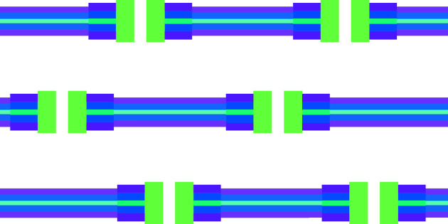
An approach to simulating small-angle X-ray and neutron scattering curves of planar bilayers with horizontally correlated inhomogeneities representing lipid domains, proteins or pores is presented.
Keywords: small-angle X-ray scattering, SAXS, small-angle neutron scattering, SANS, domains, proteins, pores, lipid bilayers, scattering length density inhomogeneities
Abstract
Model lipid bilayers have been widely employed as a minimal system to investigate the structural properties of biological membranes by small-angle X-ray (SAXS) and neutron scattering (SANS) techniques. These have nanometre resolution and can give information regarding membrane thickness and scattering length densities (SLDs) of polar and apolar regions. However, biological membranes are complex systems containing different lipids and protein species, in which lipid domains can be dynamically assembled and disassembled. Therefore, SLD variations can occur within the biomembrane. In this work, a novel method has been developed to simulate SAXS and SANS profiles obtained from large unilamellar vesicles containing SLD inhomogeneities that are spatially correlated over the membrane surface. Such inhomogeneities are represented by cylindrical entities with equivalent SLDs. Stacking of bilayers is also included in the model, with no correlation between horizontal and vertical order. The model is applied to a lipid bilayer containing SLD inhomogeneities representing pores, lipid domains, and transmembrane, partially immersed and anchored proteins. It is demonstrated that all the structural information from the host lipid bilayer and from the SLD inhomogeneity can be consistently retrieved by a combined analysis of experimental SAXS and SANS data through the methodology proposed here.
1. Introduction
Small-angle X-ray scattering (SAXS) and small-angle neutron scattering (SANS) are known to be suitable experimental techniques to investigate, at nanometric resolution, the structure of self-assembling systems formed by amphiphilic molecules, such as lipids (the main component of biological membranes) and surfactants (the molecules at the basis of detergents and cosmetics) (Glatter & Kratky, 1982 ▸). Small-angle scattering (SAS) can provide information about the shape of the aggregated structures, which basically spans from spheres to cylinders or lamellae, their dimensions and the spatial correlation between these nanosized objects. The latter comprises the signature of their lyotropic polymorphism: for instance, the typical phases observed for lipids, which are dependent on the main chemical-physical parameters, such as concentration, temperature, pressure, pH and ionic strength, are the micellar phase (direct or inverse), the hexagonal phase (direct or inverse), the lamellar phase (including the multilamellar phase formed by vesicles) and the various types of cubic phases (Mariani et al., 1988 ▸).
Concerning the study of nano-scaled model lipid bilayers (e.g. lipid vesicles dispersed in an aqueous environment), the advantage of SAXS is its dependence not only on the overall dimension of the vesicles but also on their internal structure. This is due to the spontaneous organization of amphiphilic molecules in two domains, the first hydrophobic, mainly formed by methylene groups CH2 of low electron density (which, multiplied by the classical radius of the electron r e = 0.28 × 10⁻¹² cm, gives the scattering length density, SLD) with respect to the aqueous solution, and the second polar, where the presence of electronegative atoms such as oxygen, nitrogen and phosphorus determines a high electron density. The polar domain includes hydration water molecules and, e.g. in the case of charged phospholipids, a fraction of counterions, both contributing to the polar domain average electron density.
The SAXS signal originates from the Fourier transform of the electron-density profile of the lipid bilayer, so that any electron-density variation is mapped onto the experimental SAXS intensity recorded as a function of the scattering angle. The analysis of SAXS data can be carried out through different levels of approximation. In the simplest approach, which is the most common reported in the literature (Luzzati, 1968 ▸; Guinier, 1963 ▸; Feigin & Svergun, 1987 ▸; Lindner & Zemb, 2002 ▸), the lipid bilayer thickness and the electron densities of both polar and hydrophobic domains are considered free parameters that can be determined by the best fit to the experimental SAXS curve. However, for many techniques based on scattering, different sets of parameters can lead to a similar SAXS signal. Therefore, some constraints must be imposed on the fitting parameters, for example exploiting the known physicochemical and structural properties of the lipids used. The combined analysis of SANS data over the same investigated self-assembled structures allows us to retrieve concomitantly the most appropriate fitting parameters from the SAS data. SANS is sensitive to the neutron scattering length density, which can be modified by controlling the degree of deuteration of water and lipids (Lindner & Zemb, 2002 ▸; Petrache et al., 1997 ▸; Klauda et al., 2006 ▸; Kučerka et al., 2008 ▸; Pan et al., 2015 ▸; De Rosa et al., 2018 ▸).
When the bilayers are organized in a multilamellar phase, it is possible to extract information about the structural parameters of the lamellar stacking: the SAS diffraction peaks furnish the repetition distance (e.g. the total thickness of the bilayer and water layers) from the peak position and the degree of correlation between the lamella from its width.
Although the scattering intensity from bilayers made up of only one type of lipid has been widely described, it is well established that biological membranes are more complex systems. They host proteins in different ways, whether anchored in the surface, partially immersed in the hydrophobic domain or as transmembrane proteins straddling the whole thickness of the membrane. Lipid domains formed by distinct lipids can be assembled and disassembled, providing clues to the binding of specific proteins (Sezgin et al., 2017 ▸). Further, antimicrobial peptides or toxins can promote pores in the membranes (Mesa-Galloso et al., 2021 ▸). Because of their effects on the SLD profile, all these situations may produce different but characteristic SAS curves (Heberle et al., 2013 ▸; Marquardt et al., 2015 ▸; Doktorova et al., 2019 ▸; Semeraro et al., 2021 ▸).
Different analytical or semi-analytical models have been developed to describe the form factor of spherical vesicles containing lipid domains from scattering data. Pencer et al. (2005 ▸) used coarse-grained models to calculate the form factor of radially polydisperse spherical vesicles containing a single domain or different small domains. The model was applied to fit SANS data of lipid mixtures that show phase separation at low temperatures. The contrast conditions were optimized using both deuterated and hydrogenated lipids dissolved in H2O/D2O mixtures in such a way that at high temperature, when there is no phase separation, the contrast between the lipid mixture and the solvent was zero. Interestingly, applying the coarse-grained model to SANS data of unilamellar vesicles (LUV) of DOPC:DPPC:cholesterol1 (molar ratio 1:1:1), the authors showed that, at room temperature, each LUV displayed approximately 30 lipid domains of average radius 100 Å. A coarse-grained approach for calculating the form factor of polydisperse spherical vesicles forming lipid domains was also used by Heberle et al. (2013 ▸) and applied to analyse SANS data of lipid mixtures of DOPC:POPC:DSPC:cholesterol under optimal contrast conditions, with the aim of calculating bilayer thickness and domain size. The authors obtained values of domain radius and number of domains that could vary from 68 Å and 23 domains to 225 Å for one to four domains, respectively, depending on the molar ratio of the lipids. Anghel et al. (2007 ▸) utilized, for the first time, the powerful spherical harmonic approach (Stuhrmann, 1970 ▸; Svergun & Stuhrmann, 1991 ▸; Spinozzi et al., 1998 ▸) to calculate the form factor of a spherical vesicle containing one circular nanodomain. This approach was then extended (Heberle et al., 2015 ▸) and the analytical form factor for the case of several domains of arbitrary size and spatial configuration was derived. In subsequent work, Anghel et al. (2018 ▸, 2019 ▸) calculated the correlation between domains in the case of vesicles containing two or three domains. For vesicles with more than three domains, they simulated the correlation between domains using a Monte Carlo method, the results of which were subsequently interpreted using a Percus–Yevick equation in spherical geometry combined with the Ornstein–Zernike relation. Dorrell et al. (2020 ▸) developed an advanced method to calculate the SANS curves of highly curved and fluctuating vesicles. This method combines a molecular and a continuum approach to discriminate between inner and outer leaflets of the vesicle. Recently, Krzyzanowski et al. (2023 ▸) have analysed SANS curves of a mixture of two lipids, DLPC and DPPC, that exhibits solidus–liquidus phase coexistence by using a bead model to calculate the form factor of polydisperse vesicles.
Most of the articles cited above concern the study, especially by SANS, of small polydisperse spherical vesicles (diameter 300–600 Å) in which there are circular domains having a constant SLD. The effects of the curvature and the total vesicle area are important constraints to establish the number and size of the domains. In this work we use a different approach. We work exclusively in planar geometry, thus assuming that the radius of the vesicle is so large that it does not show curvature effects or limit the number of domains. We describe how the SAS curves from such flat lipid bilayers are affected by the presence of SLD inhomogeneities such as those arising from pores, lipid domains and membrane proteins, and how structural information about these inhomogeneities can be retrieved by model fitting. In particular, we simulate SAXS and SANS profiles for lipid bilayers containing DOPC and DPPC phospholipids and a certain number of laterally correlated SLD inhomogeneities (hereafter referred to as ‘islands’), defined as cylindrical entities representing lipid domains, pores, aqueous channel-forming proteins, anchored proteins, or partially immersed or transmembrane proteins, taking into account their SLDs. The resulting SLD inhomogeneity model has been integrated into the GENFIT software (Spinozzi et al., 2014 ▸), freely available at https://sites.google.com/site/genfitweb/, and was used to fit the simulated curves. The good agreement between fitted and simulated profiles obtained in the different investigated cases confirms the robustness of the method. The model also includes the possibility of bilayer stacking with no correlation between horizontal and vertical order.
2. Model development
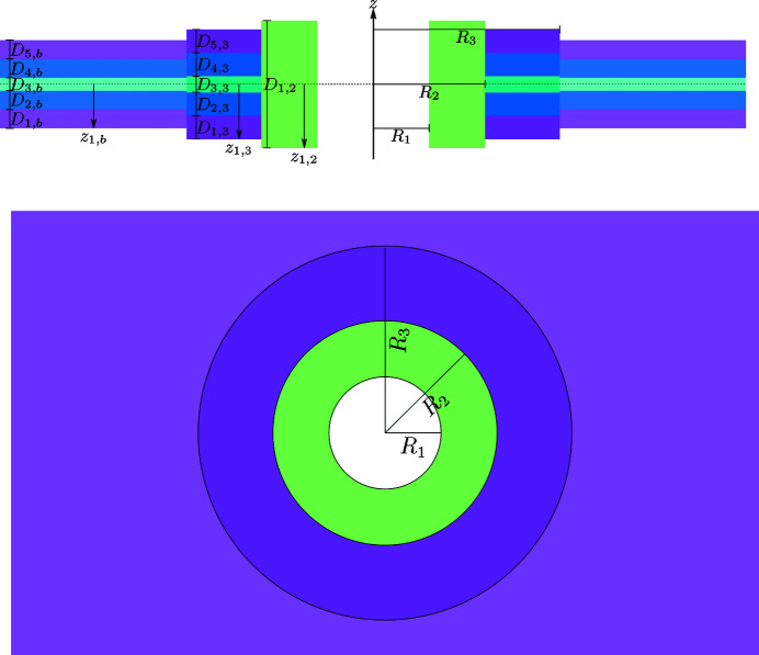
To take into account possible SLD inhomogeneities in the SAS profiles of lipid bilayers, the following methodology has been developed. First, we consider a solution of randomly oriented stacks of N parallel bilayers. Associated with each bilayer are M identical islands, described by N s cylindrical shells of SLD inhomogeneities with their common axis perpendicular to the bilayer surface (Fig. 1 ▸). We assume that the bilayer surface is the area of a circle with radius R b much greater than the typical bilayer thickness.
Figure 1.
Schematic diagram of stacking of bilayers with SLD inhomogeneities (referred to as islands throughout the paper). The island-free bilayer is described by N b = 5 levels of SLD, represented by magenta (lipid polar head group), blue (alkyl chains of the lipids), cyan (the inner part of the bilayer rich in CH3 groups), blue and magenta layers, in order. The island contains N s = 3 cylindrical shells with the following levels of SLD: N 1 = 0 (white hole), N 2 = 1 (green layer), N 3 = 5 (dark magenta, dark blue, dark cyan, dark blue and dark magenta layers).
The SLD of the system at the point
 (
(
 is the unit vector in the direction perpendicular to the bilayer xy plane) can be written as
 |
where z n is the vertical displacement of the nth bilayer and r ∥nm is the two-dimensional vector in the xy plane of the nth bilayer that gives the position of the centre of the mth island. ρ0 is the solvent SLD. Referring to a bilayer placed at the centre of the reference system, the function s b(r ∥) is equal to 1 when |r ∥| ≤ R b and 0 otherwise. The bilayer SLD profile along the z axis is described by the function ρb(z). On the other hand, when the origin is at the centre of an island, the function s k (r ∥) is 1 when the point r ∥ belongs to the kth cylindrical shell of the island, whose SLD profile along the z axis is ρ k (z); otherwise it is 0. The scattering amplitude is the Fourier transform of the SLD [equation (1)] in excess with respect to ρ0,
 |
The scattering vector, defined as q =
 +
+
 +
+
 (
(
 and
and
 being unit vectors along the axes x and y, respectively), is also written as q
 . We have introduced the following four partial amplitudes,
A
b(q
⊥) is the Fourier transform of the SLD of the bilayer without islands in excess with respect to the solvent, A
k
(q
⊥) is the Fourier transform of the SLD of the kth cylindrical shell that exceeds the corresponding SLD of the bilayer without islands,
 is the xy Fourier transform of the surface of the whole bilayer without islands, and finally
 is the xy Fourier transform of the kth circular shell on the bilayer surface.
All the SLD profiles along the z axis, ρ l (z) [with l standing for the bilayer without islands (l = b) or the kth cylindrical shell of the island (l = k)], are modelled by an N l -level function, with transitions between two successive levels described by the smooth error function erf(z) (Spinozzi et al., 2010 ▸).
where z j,l is the z coordinate of the jth level of the lth profile with thickness D j,l ,
 |
and σ
j,l
is the smoothness of the transition between the (j − 1)th and the jth levels (Fig. 2 ▸). In equation (8), we set
 . Note that the expression above does not assume any symmetry of ρ
l
(z).
Figure 2.
A representation of an island in a bilayer with the geometric parameters indicated. The bilayer contains N b = 5 levels of SLD, colour coded as in Fig. 1. The island contains N s = 3 cylindrical shells with the following levels of SLD: N 1 = 0, N 2 = 1, N 3 = 5 (see Fig. 1 ▸ caption).
According to these assumptions, the four amplitudes in equations (4)–(7 ) become the following analytical expressions:
 |
 |
where J 1(x) are the first Bessel functions of integer order, and R k represents the radius of the kth cylindrical shell of the island, with R 0 ≡ 0 by definition.
At q = 0, the asymptotic values of these functions are
The modulus square of the scattering amplitude becomes
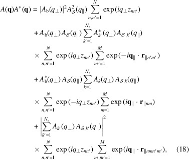 |
where
 and
and
 . By averaging over all possible stacks of the bilayer (z
n
) and all possible positions of islands (r
∥nm
) and by assuming that there is no correlation between vertical and horizontal order, the previous equation transforms into
 |
where we have introduced the 1D bilayer–bilayer structure factor,
and the 2D island and island–island structure factors,
The angle brackets represent the averages over the distribution of stacking distances
 [equation (20)], island positions r
∥nm
[equation (21)] and island–island distances
 [equation (22)]. We assume that the island distribution along the xy bilayer plane is described by the well known paracrystal theory (PT) in two dimensions (Hosemann & Bagchi, 1952 ▸, 1962 ▸; Hosemann et al., 1967 ▸; Wilke, 1983 ▸; Matsuoka et al., 1987 ▸; Lazzari, 2002 ▸; Frühwirth et al., 2004 ▸). Firstly, we consider that the island distribution along the xy bilayer plane is based on a distorted two-dimensional hexagonal lattice, with unit-cell vectors
 and
and
 . The lattice parameter a represents the average island–island distance. Secondly, along both directions a
1 and a
2, we assume a unique average number, N
a
= M
1/2, of islands with a unique distortion factor, g
a
= σ
a
/a, σ
a
being the Gaussian standard deviation of the isotropic distortion. Note that the lattice parameter a establishes the surface density of the islands, according to
Clearly, the distance between two islands cannot be less than twice the maximum radius of the island,
 . The probability of finding an island at a distance r
∥ from the first island is given by the convolution of the probability of finding an island at a distance
 with respect to the first array along a
1 and the probability of finding an island at a distance
 with respect to the second array along a
2,
In turn, the probability
 is obtained by summing the convolutions of the 2D Gaussian functions
Note that the lattice vector a k is given by
and the unique standard deviation by
for any k = 1, 2 and component l = x, y. The island structure factor is the Fourier transform of p d (r ∥),
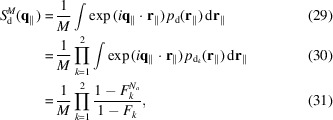 |
The probability of finding a pair of islands at a mutual distance r ∥ is similarly obtained by the convolution of two pair probabilities,
and each probability, according to PT theory, is given by a combination of convoluted Gaussians,
The island–island structure factor is clearly the Fourier transform of p dd(r ∥),
 |
The bilayer–bilayer structure factor is calculated on the basis of one unit vector,
 , c being the average stacking distance. According to Frühwirth et al. (2004 ▸), considering a stack of N bilayers with islands, the bilayer–bilayer structure factor can be written following the PT theory or the modified Caillé theory (MCT) as
with T = PT or MCT, where
 |
g c⊥ is the perpendicular distortion factor, η1 is the Caillé parameter and γ is Euler’s constant. According to Zhang et al. (1996 ▸), the distortion factor can be expressed in terms of η1, g c⊥ = (0.087η1)1/2. Polydispersity over N should be introduced in order to eliminate ‘intrinsic’ oscillations of the monodisperse paracrystalline structure factor at low q that have never been seen in experimental data (Frühwirth et al., 2004 ▸). Sampling points are weighted by a discrete Gaussian distribution, as shown in equations (S1) and (S2) of the supporting information.
The differential scattering cross section per bilayer is obtained by calculating the orientational average of the squared modulus of the amplitude [equation (19)] and dividing by N,
 |
where
 and
and
 denote the zenith and azimuth averages, namely
 and
and
 , respectively.
For a large bilayer radius (qR
b ≫ 1) the factor
 in the average integral over
 of the first term of equation (42) is dominated by asymptotic behaviour,
δ(β
q
) being the Dirac δ function. By similar arguments, it can be shown that the factor
 belonging to the average integral over
 in the second term of equation (42) has the following asymptotic behaviour:
However, according to equation (23), for large R
b the number of islands M also becomes large and, on the basis of equation (31), the island structure factor
 drops to zero apart from
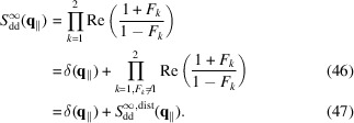
 (see Fig. S1 in the supporting information). Under these conditions equation (42) reduces to
 |
According to equation (37), the island–island structure factor for an infinite two-dimensional paracrystal is
 |
A final equation that describes the experimental scattering intensity (more properly called ‘macroscopic differential scattering cross section’) in terms of
 should be given by
where c
V
is the volume fraction of the whole scattering matter in the system and V is the volume of a single bilayer with islands. Here κ and B represent a scaling factor and a flat background, respectively, both due to instrumental effects. Note that, in the case of SANS, B could be due to incoherent neutron scattering phenomena. The volume V of a bilayer with islands can be expressed as a function of the thickness of a bilayer without islands,
 , and the thickness of the cylindrical shells,
 ,
,
 |
 |
where
In conclusion, the scattering intensity to be fitted to the experimental data becomes a function that does not depend on R b,
 |
The model developed here, described by equation (52), is named SASBIN and is integrated in the GENFIT software (Spinozzi et al., 2014 ▸). Interestingly, considering no multilayer stacking [
 =
=
 = 1] in equation (52), two limit cases may call our attention. Firstly, in the case where one has a very large island-containing bilayer, and hence the distances a between the islands are also very large (n
d is quite small), the resulting scattering is a mixture of two independent scatterings from the flat surfaces (bilayer and island) [see Section S2 for in-depth detail, equation (S5)]. Secondly, in the case of very small islands distributed in the lipid bilayer, the scattering intensity resolves to that of a homogeneous bilayer given by a mixture of the two electron-density profiles from the bilayer and the islands [see Section S2, equation (S10)].
In the following, we present some examples of SAXS profiles from lipid bilayers containing different scatterers, such as proteins immersed or not in the hydrophobic medium, and lipid domains with distinct SLDs with respect to the host bilayer. The question of how the presence of pores impacts on the lipid bilayer scattering will also be addressed. The corresponding SANS profiles are presented in the supporting information.
3. Results and discussion
3.1. Lipid domains
It is well known that the presence of domains in lipid bilayers can be recognized by the presence of distinct lamellar diffraction peaks over the lipid bilayer form factor measured from SAS multilamellar vesicles (Heftberger et al., 2015 ▸). SANS data performed on LUVs made of a mixture of deuterated and protonated lipids of different species can give information on the protonated lipid domain size, provided the deuterated portion matches the SLD of D2O/H2O (Pencer et al., 2005 ▸; Kinnun et al., 2023 ▸; Heberle et al., 2013 ▸). Here, we demonstrate the possibility of extracting this information from SAXS (and SANS) curves simulated according to our modelling, without the need for using SLD contrast matching.
Fig. 3 ▸ shows simulations of SAXS curves obtained using equation (52) (with κ = 1 and B = 0) of fluid–gel lipid phases formed by the coexistence of DOPC (aliphatic chains in fluid conformation) in a bilayer of DPPC (aliphatic chains in gel conformation). A schematic representation is shown in Fig. S2. Corresponding SANS curves in pure D2O (deuteration grade x D = 1) are shown in Fig. S3. All calculations have been done with C DPPC = 3 mM. Three distortion factors have been applied to the simulations (g a = 0.1, 0.2 and 0.3). For the lower g a factor, i.e. a low distortion factor with respect to the hexagonal array of SLDs proposed in the model, small diffraction peaks could appear over the scattering curves (Fig. S4). To be more realistic regarding SLDs distributed in a lipid bilayer system, we choose to show here all simulations with g a = 0.3.
Figure 3.
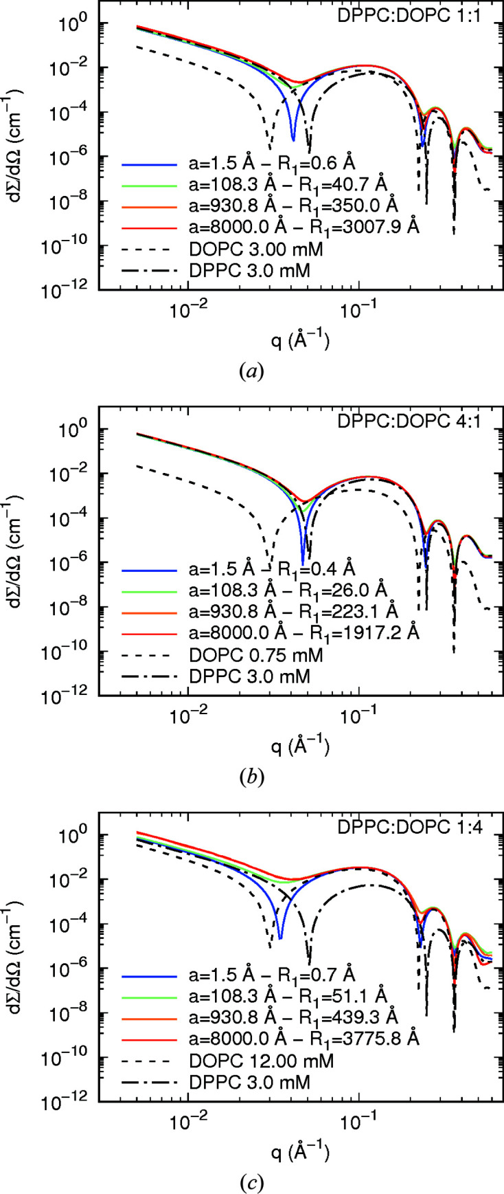
Simulated SAXS curves from coexisting DOPC fluid phase–DPPC gel phase. C DPPC = 3 mM and the lattice distortion factor g a = 0.3. a corresponds to the centre-to-centre distance between the DOPC lipid domains dispersed in the DPPC host bilayer. R 1 corresponds to the radius of a cylindrical island representing a domain (Fig. S2). The surface density of domains, according to equation (23), ranges from 0.51 Å−2 to 1.8 × 10⁻⁸ Å−2.
Figs. 3 ▸(a), 3 ▸(b) and 3 ▸(c) correspond to different DPPC:DOPC molar ratios, as indicated. In each panel, the curves refer to different sets of the lattice distance a and domain radius R
1, which are related to the concentrations of DPPC and DOPC according to a
2 =

 , where a
DPPC and a
DOPC are the areas per molecule in the bilayer. For both lipids, the area per molecule a
l
(with l = b for DPPC and l = 1 for DOPC), the volume v
l
, the thicknesses D
j,l
, the corresponding electron densities ρ
j,l,X and neutron SLDs in pure D2O ρ
j,l,N (the region index j = 1, 2, 3 referring to the polar head region, the intermediate hydrophobic region rich in CH2 and the terminal region rich in CH3, respectively), and the smoothness parameters σ
j,l
are shown in Table 1 ▸. They have been calculated by the best fit with equation (10) to the form factors of pure DPPC and DOPC obtained with the chemical group model (De Rosa et al., 2018 ▸). The volume fraction of the sample, seen in equation (52), is c
V
= N
A(C
DPPC
v
DPPC + C
DOPC
v
DOPC), where N
A is Avogadro’s number.
Table 1. DPPC and DOPC parameters used in the simulations.
| Parameter | DPPC (l = b) | DOPC (l = 1) |
|---|---|---|
| a l (Å2) | 57 | 60 |
| v l (Å3) | 1140 | 1270 |
| D 1,l (Å) | 12.0 | 11.9 |
| D 2,l (Å) | 10.7 | 9.9 |
| D 3,l (Å) | 3.50 | 5.87 |
| ρ1,l,X (e Å−3) | 0.412 | 0.408 |
| ρ2,l,X (e Å−3) | 0.317 | 0.302 |
| ρ3,l,X (e Å−3) | 0.245 | 0.264 |
| ρ1,l,N (10−6 Å−2) | 4.203 | 4.294 |
| ρ2,l,N (10−6 Å−2) | −0.349 | −0.265 |
| ρ3,l,N (10−6 Å−2) | −0.602 | −0.446 |
| σ1,l (Å) | 2.49 | 3.50 |
| σ2,l (Å) | 2.39 | 3.48 |
| σ3,l (Å) | 2.01 | 4.02 |
In all panels of Fig. 3 ▸, SAXS curves of pure DOPC and pure DPPC are shown for comparison. Note that, at a DOPC:DPPC molar ratio of 1:1 [Fig. 3 ▸(a)], the resulting scattering has the minima of the form factor as the mean q positions between the minima of the DPPC and DOPC scattering curves. These minima are displaced towards the minima of the DPPC or DOPC SAXS curves according to the increase in the amount of DPPC or DOPC in the lipid bilayer, respectively [Figs. 3 ▸(b) and 3 ▸(c)]. Interestingly, for a small DOPC domain size (a = 1.5 Å) one can clearly observe a deep first minimum arising from the mixture of the two electron-density profiles, taking into account the surface fraction of each component [DOPC domains and the DPPC bilayer, equation (S10) of the supporting information]. On the other hand, for large DOPC domains, the minima become very shallow with respect to those observed from small domains, reflecting the fact that the scattering of two independent scatterers is also weighted by the surface fraction of each component [equation (S5) of the supporting information]. It is evident that the size of the domain, i.e. the radius R 1 of the island representing an SLD inhomogeneity, can be retrieved from the SAXS curve since the depth of the minima of the oscillations is related to the parameter a and hence to R 1 [see, for instance, the result presented for a = 108.3 Å, green lines in Figs. 3 ▸(a)–3(c)]. The scattering intensities dΣ/dΩ(q) also depend on the a (and R 1) values, since they are related to the surface density of the islands n d according to equation (52). The SANS profiles display significant differences on changing the a parameter and DOPC:DPPC molar ratio (Fig. S3). As a consequence, a combined SAXS/SANS analysis can give strong support to the structural parameters obtained from lipid-domain-containing bilayers. As an example, we present the consistency of the combined SAXS/SANS data analysis performed by the GENFIT software from a lipid bilayer composed of DOPC:DPPC in a 1:1 molar ratio, with input parameters a = 150 Å, R 1 = 60 Å and g a = 0.3 (see Fig. 4 ▸ and Table 2 ▸). Note that the output parameters are quite similar to the ones considered as input parameters.
Figure 4.
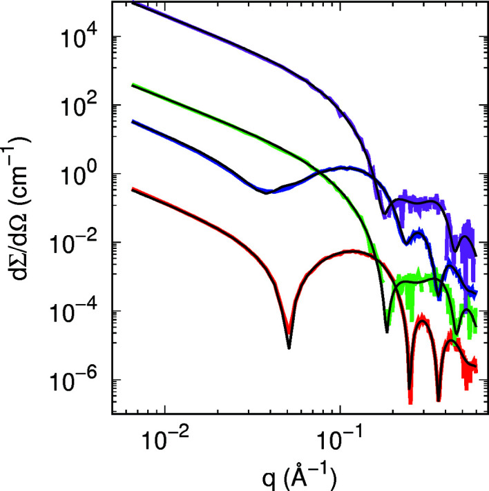
Best global fits (black lines) of simulated SAXS (red and blue lines) and SANS (green and magenta lines) curves of 3 mM DPPC and DOPC domains in 3 mM DPPC, respectively (g a = 0.3, a = 150 Å, R 1 = 60 Å, corresponding to C DOPC = 3.94 mM). The simulated curves have been randomly moved by sampling from a Gaussian distribution with standard deviation proportional to [dΣ/dΩ(q)]1/2. Curves are vertically displaced for clarity.
Table 2. Parameters from the best fit to the SAS curves shown in Fig. 4 ▸ representing DOPC domains in a DPPC bilayer.
The length unit is ångströms. For X-rays, electron densities are expressed in e Å−3. For neutrons, SLDs are expressed in 10−6 Å−2.
| Parameter | In | Out |
|---|---|---|
| R 1 | 60.0 | 59 ± 1 |
| D 1,b | 12.0 | 12.01 ± 0.03 |
| D 2,b | 10.6 | 10.78 ± 0.03 |
| D 3,b | 3.64 | 3.45 ± 0.04 |
| ρ1,b,X | 0.411 | 0.4123 ± 0.0002 |
| ρ1,b,N | 4.29 | 4.22 ± 0.03 |
| ρ2,b,X | 0.316 | 0.3163 ± 0.0001 |
| ρ2,b,N | −0.618 | −0.76 ± 0.02 |
| ρ3,b,X | 0.247 | 0.2427 ± 0.0006 |
| ρ3, b, N | −0.126 | −0.15 ± 0.07 |
| σ1,b | 2.56 | 2.71 ± 0.04 |
| σ2,b | 2.22 | 2.30 ± 0.04 |
| σ3,b | 1.74 | 2.05 ± 0.06 |
| D 1,1 | 12.3 | 12.47 ± 0.06 |
| D 2,1 | 12.3 | 11.60 ± 0.05 |
| D 3,1 | 3.13 | 3.74 ± 0.03 |
| ρ1,1,X | 0.407 | 0.4054 ± 0.0003 |
| ρ1,1,N | 4.33 | 4.19 ± 0.04 |
| ρ2,1,X | 0.296 | 0.2965 ± 0.0002 |
| ρ2,1,N | −0.529 | −0.59 ± 0.08 |
| ρ3,1,X | 0.246 | 0.2578 ± 0.0008 |
| ρ3,1,N | −0.106 | −0.21 ± 0.07 |
| σ1,1 | 3.47 | 3.40 ± 0.07 |
| σ2,1 | 3.51 | 3.24 ± 0.09 |
| σ3,1 | 4.12 | 3.0 ± 0.2 |
| g a | 0.300 | 0.197 ± 0.002 |
3.2. Proteins-containing lipid bilayers
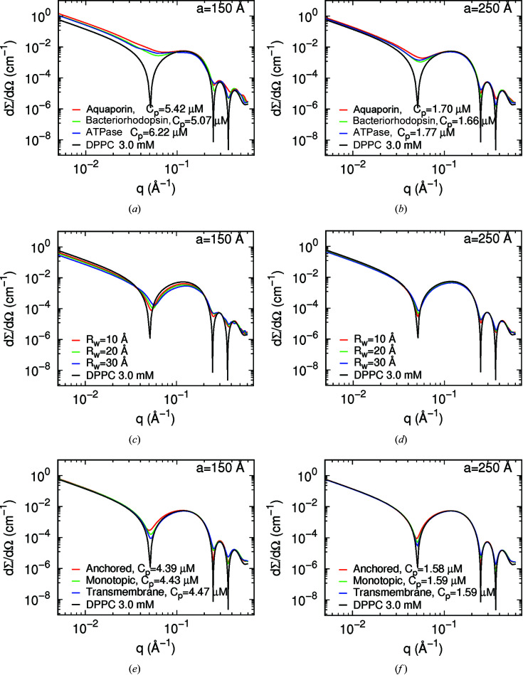
Fig. 5 ▸ shows the simulated SAXS curves obtained with a = 150 Å (left-hand panels) and a = 250 Å (right-hand panels) for three transmembrane proteins [panels (a) and (b)], for water pores [panels (c) and (d)] and for cytochrome c in different positions with respect to the bilayer centre [panels (e) and (f)]. Such systems are represented in Figs. S5–S8. In all cases, the simulations have been done at 3 mM DPPC and with a unique island–island distortion factor g a = 0.3. Corresponding SANS simulations at x D = 1 are shown in Fig. S9.
Figure 5.
Simulated SAXS curves of islands in a DPPC bilayer at C DPPC = 3 mM according to the SASBIN model. (a) and (b) Three different transmembrane proteins (as indicated) with lattice parameter a of (a) 150 Å and (b) 250 Å. (c) and (d) Three different water pores (with indicated pore radius R w) with lattice parameter a of (c) 150 Å and (d) 250 Å. (e) and (f) Three different positions of cytochrome c (as indicated) with lattice parameter a of (e) 150 Å and (f) 250 Å. In all cases the distortion parameter is g a = 0.3.
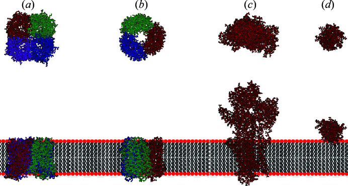
The form factors of each protein (represented in Fig. 6 ▸) were determined with the SASMOL method (Ortore et al., 2009 ▸) without considering the difference in the mass density between the first hydration shell water and bulk water. Subsequently, the calculated form factors were fitted with a core–shell cylinder model, according to equation (S11) shown in the supporting information. Note that this approximation is necessary in order subsequently to describe the proteins embedded in the membranes using the island model introduced in Section 2. The fitting parameters are the radius R of the cylinder core, the shell thickness δ, and the fractions ϕi and ϕe of polypeptide matter in the core and shell regions, respectively, described in Table 3 ▸. Curves simulated with SASMOL and the best fits obtained by the core–shell cylinder model are shown in Fig. S10. The fitted parameters were related to the cylindrical islands used to describe the structures of the transmembrane proteins (aquaporin, bacteriorhodopsin and ATPase) in a DPPC bilayer with the SASBIN model. In detail, the island is formed by two cylindrical shells (N
s = 2), with N
1 = 1 and N
2 = 1. The corresponding radii are R
1 = R and R
2 = R + δ and the SLDs are those obtained by the core–shell cylinder model [equations (S13) and (S14) of the supporting information]. The thicknesses are D
1,1 = D
1,2 = L. For aquaporin and bacteriorhodopsin, to simulate perfect positioning within the bilayer, we set z
1,1 = z
1,2 = −L/2. On the other hand, for ATPase, since almost half of the protein’s longest dimension is embedded in the bilayer [see Fig. 6 ▸(c)], we set z
1,1 = z
1,2 = −L/4. Considering the area of the protein towards the xy plane,
 , and the area per polar head of DPPC, a
DPPC, an expression of the protein concentration C
p as a function of the lattice parameter a can be easily derived, C
p = C
b
a
DPPC/[(31/2)a
2 − 2a
p]. Values are reported in the legends of Fig. 5 ▸(a) and 5 ▸(b). The volume fraction of the sample is c
V
= N
A(C
b
v
DPPC + C
p
v
p).
Figure 6.
Ribbon representations of (a) aquaporin (PDB code 3d9s; Horsefield et al., 2008 ▸), (b) bacteriorhodopsin (PDB code 1fbb; Subramaniam & Henderson, 2000 ▸), (c) ATPase (PDB code 3wgv; Kanai et al., 2003 ▸) and (d) cytochrome c (PDB code 1giw; Banci et al., 1999 ▸). (Top row) Views in the xy plane of the membrane. (Bottom row) Views across the membrane (xz plane) together with a cartoon representation of the lipid bilayer.
Table 3. Protein parameters used in the simulations of SAXS and SANS curves shown in Fig. S10 .
| Aquaporin (PDB 3d9s) | Bacteriorhodopsin (PDB 1fbb) | ATPase (PDB 3wgv) | Cytochrome c (PDB 1giw) | |
|---|---|---|---|---|
| M w (g mol−1) | 102 505 | 73 690 | 109 942 | 11 721 |
| V p (Å3) | 133 006 | 96 506 | 138 965 | 14 839 |
| R (Å) | 5.78 | 8.01 | 18.2 | 0.262 |
| δ (Å) | 28.6 | 21.0 | 24.6 | 15.0 |
| ϕi | 0.211 | 0.0195 | 1.00 | 0.718 |
| ϕe | 0.904 | 0.870 | 0.0557 | 0.886 |
| L † (Å) | 41.4 | 45.5 | 107 | 22.8 |
| ρp,X (e Å−3) | 0.411 | 0.411 | 0.420 | 0.420 |
| ρp,N (10−6 Å−2) | 2.828 | 2.732 | 3.009 | 3.119 |
Input parameters are derived parameters.
It should be noted that a values of 150 and 250 Å were chosen because the largest studied protein radius (ATPase) is 42.8 Å, i.e. a total cylindrical diameter of ca 86 Å. Thus, the distance between the islands was less than twice or three times their diameter, for comparison. Furthermore, each of the transmembrane proteins has an aqueous pore of different dimension ranging from 5.8 to 18 Å (Table 3 ▸). Although the proteins produce different scattering profiles with respect to the protein-free DPPC bilayer [Figs. 5 ▸(a) and 5 ▸(b)], the most marked effect is the smoothness of the oscillation minima, which is correlated to the a values as discussed for lipid domains. Note that the ratio between the first, second and third minimum depths can vary depending on the protein species. Moreover, the scattering intensity varies with SLD contrast between the island and the surrounding medium. In the case of SANS profiles (Fig. S9), all investigated protein profiles are quite distinguishable for q values between 0.2 and 0.4 Å−1. Therefore, the combined SAXS/SANS experiments allow us to obtain information about the dimensions of the immersed proteins in the lipid bilayer. For the sake of validation, Fig. 7 ▸ shows the simulated SAXS and SANS experiments for bacteriorhodopsin, along with the best fitting result obtained with GENFIT, while Table 4 ▸ displays the input and output fitting parameters. The good agreement between them confirms the robustness of the SASBIN method. For the sake of completeness, further GENFIT analyses of simulated SAXS/SANS curves regarding aquaporin and ATPase in a DPPC bilayer are reported in Figs. S11 and S12, respectively, and the fitting parameters are shown in Tables S1 and S2.
Figure 7.
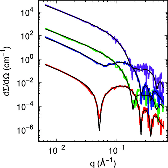
Best global fits (black lines) of SAXS (red and blue lines) and SANS (green and magenta lines) curves of DPPC and bacteriorhodopsin in DPPC according to the simulations shown in Fig. 5 ▸(a) and Fig. S9(a). The simulated curves have been randomly moved by sampling from a Gaussian distribution with standard deviation proportional to [dΣ/dΩ(q)]1/2. Curves are vertically displaced for clarity.
Table 4. Best fit parameters of the curves shown in Fig. 7 ▸ representing the transmembrane protein bacteriorhodopsin in a DPPC bilayer.
The length unit is ångströms. For X-rays, electron densities are expressed in e Å−3. For neutrons, SLDs are expressed in 10−6 Å−2.
| In | Out | |
|---|---|---|
| R 1 | 8.01 | 8 ± 1 |
| t | 21.0 | 20.8 ± 0.6 |
| ϕe | 0.870 | 0.800 ± 0.003 |
| ϕi | 0.0195 | 0.05 ± 0.02 |
| L † | 45.5 | 49.2 ± 0.7 |
| D 1,b | 12.0 | 11.6 ± 0.2 |
| D 2,b | 10.6 | 11.3 ± 0.1 |
| D 3,b | 3.64 | 3.0 ± 0.1 |
| ρ1,b,X | 0.411 | 0.414 ± 0.001 |
| ρ1,b,N | 4.29 | 4.26 ± 0.05 |
| ρ2,b,X | 0.316 | 0.318 ± 0.001 |
| ρ2,b,N | −0.618 | −0.80 ± 0.06 |
| ρ3,b,X | 0.247 | 0.231 ± 0.002 |
| ρ3,b,N | −0.126 | −0.2 ± 0.3 |
| σ1,b | 2.56 | 2.9 ± 0.2 |
| σ2,b | 2.22 | 2.34 ± 0.07 |
| σ3,b | 1.74 | 2.4 ± 0.2 |
| g a | 0.300 | 0.36 ± 0.02 |
Input parameters are derived parameters.
The case of cytochrome c, here simply considered an example of a model protein that could interact differently with a membrane in an anchored (ξ = 0), a monotopic (ξ = 1/2) or a transmembrane geometry (ξ = 1), is different. For an anchored configuration, we have, for both shells (N s = 2, with radii R 1 = R and R 2 = R + δ), six levels (N 1 = N 2 = 6), the first five levels being equal to those of the bilayer and the sixth level constituted by the protein. For a monotopic configuration, for both shells (N s = 2, with radii R 1 = R and R 2 = R + δ) we have four levels, the first three levels being equal to those of the bilayer and the fourth level constituted by the protein. The protein concentration is related to the lattice parameter by C p = C b a DPPC/[(31/2)a 2 − 2ξa p]. Simulated SAXS and SANS curves for the three cases are shown in Figs. 5 ▸(e) and 5 ▸(f) and Figs. S9(e) and S9(f), respectively.
As one can see from Figs. 5 ▸(e) and 5(f), the signature of anchored, monotopic and transmembrane proteins can also be verified through the ratio between the minimum depths from SAXS curves, whereas differences in the SANS profiles with respect to the cytochrome c free DPPC membrane mainly occurs at q ranging from 0.2 to 0.4 Å−1. Once again, one can retrieve significant information about anchoring or intercalation of the protein in the lipid membrane from combined SAXS/SANS data analysis. As an example, Fig. 8 ▸ presents the simulated experiment along with the best fitting result, and Table 5 ▸ displays the input and output fitting parameters, for cytochrome c in a monotopic configuration, demonstrating the completeness of the methodology used here.
Figure 8.
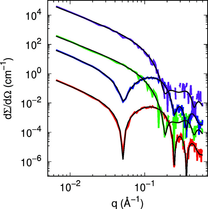
Best global fits (black lines) of SAXS (red and blue lines) and SANS (green and magenta lines) curves of DPPC and cytochrome c in DPPC in the monotopic configuration according to the simulations shown in Fig. 5 ▸(e) and Fig. S9(e). The simulated curves have been randomly moved by sampling from a Gaussian distribution with standard deviation proportional to [dΣ/dΩ(q)]1/2. Curves are vertically displaced for clarity.
Table 5. Best fit parameters of curves shown in Fig. 8 ▸ representing cytochrome c in a DPPC bilayer with a monotopic configuration.
The length unit is ångströms. For X-rays, electron densities are expressed in e Å−3. For neutrons, SLDs are expressed in 10−6 Å−2.
| In | Out | |
|---|---|---|
| R 1 | 0.262 | 1.9 ± 0.7 |
| δ | 15.0 | 12 ± 1 |
| ϕe | 0.886 | 1.0 ± 0.1 |
| ϕi | 0.718 | 1.0 ± 0.2 |
| L † | 22.8 | 22 ± 1 |
| ξ | 0.500 | 0.7 ± 0.2 |
| D 1,b | 12.0 | 11.9 ± 0.1 |
| D 2,b | 10.6 | 11.07 ± 0.06 |
| D 3,b | 3.64 | 3.12 ± 0.04 |
| ρ1,b,X | 0.411 | 0.414 ± 0.001 |
| ρ1,b,N | 4.29 | 4.25 ± 0.07 |
| ρ2,b,X | 0.316 | 0.3143 ± 0.0008 |
| ρ2,b,N | −0.618 | −0.61 ± 0.08 |
| ρ3,b,X | 0.247 | 0.241 ± 0.001 |
| ρ3,b,N | −0.126 | −0.3 ± 0.2 |
| σ1,b | 2.56 | 2.69 ± 0.08 |
| σ2,b | 2.22 | 2.5 ± 0.1 |
| σ3,b | 1.74 | 1.6 ± 0.1 |
| g a | 0.300 | 0.42 ± 0.03 |
Input parameters are derived parameters.
3.3. Pore-containing membranes
Water pores with radius R w are described by the geometry of the inner surface of a torus (Spinozzi et al., 2010 ▸). A representation is provided in Fig. S6. This geometry is mapped onto a three-level cylinder island (N s = 3), with radii R 1 = R w, R 2 = R w + D 1,b and R 3 = R w + D 1,b + D 2,b + D 3,b, and the corresponding number of SLD levels N 1 = 0, N 2 = 1 and N 3 = 3. The lower z level of the first shell z 1,2 and the thickness of the region D 1,2 are analytically calculated in such a way that the volume of the cylindrical shell is equal to the volume of the part of the inner torus with an x projection between −R 2 and −R 1, as shown in Fig. S6. The lower z level of the second shell z 1,3 and the thicknesses of the two regions D 1,2 and D 2,2 are calculated in such a way that the volumes of the two cylindrical shells are equal to the volumes of the two parts of the inner torus with an x projection between −R 3 and −R 2, as shown in Fig. S6. The results lead to these expressions: z 1,1 = −F 6 D 1,b, D 1,1 = 2F 6 D 1,b, z 1,2 = −F 7 D 1,b + F 4 F 1, D 1,2 = F 7 D 1,b and D 2,2 = 2F 4 F 1. The factors F 1 to F 7 are given in Section S4. Note that they depend on the pore radius R w. Simulated SAXS and SANS curves for the three values of R w are shown in Figs. 5 ▸(c) and 5 ▸(d) and in Figs. S9(c) and S9(d), respectively.
As one can see from Figs. 5 ▸(c) and 5 ▸(d), it is possible to recognize different pore dimensions, ranging from 10 to 30 Å, from the SAXS curves since the scattering profiles may have different minimum q positions and the intensities are smaller than those produced by a pore-free bilayer, due to differences in the SLD contrast between the pore and the bilayer. Concomitantly, the SANS curves also reflect the scattering differences of membranes containing pores [Figs. S9(c) and S9(d)]. Therefore, the combined SANS/SAXS results can furnish the values of the pore radius R w, such as those produced for instance by peptides and toxins interacting with membranes, and of the numerical density n d when SLD inhomogeneities are accounted for as here proposed by the SASBIN model.
4. Concluding remarks
Small-angle X-ray and neutron scattering have traditionally been used to determine the structure of single-component biomimetic membranes that can be represented by unilamellar and multilamellar vesicles. SAXS and SANS intensities over a q range are intrinsically related to the Fourier transform of the SLD profile of the lipid bilayer. In the simplest analysis commonly reported in the literature, the lipid bilayer thickness and the SLDs of both polar and hydrophobic regions are considered free parameters that can be determined by the best fit to the experimental SAS curve. More recently, a method considering the scattering of lipid chemical groups has been introduced in the literature (Wiener & White, 1991a ▸,b ▸; Pan et al., 2015 ▸, 2012 ▸; De Rosa et al., 2018 ▸) which allows us to extract more in-depth structural details of membranes composed of a mixture of lipids. SANS has also been applied to investigating the size of lipid domains by contrast matching (Pencer et al., 2005 ▸; Heberle et al., 2013 ▸) and proteins inserted into the membrane (Spinozzi et al., 2022 ▸). In this work, we have presented the new SASBIN model to analyse SAXS and SANS curves from large unilamellar vesicles containing SLD inhomogeneities. These may represent pores and lipid domains distributed in the lipid bilayer, or proteins anchored or immersed in the membrane. Through development of the SASBIN model, we have shown it is possible to recognize the presence of inhomogeneities in the SAS curves, and their dimensions and spatial distribution.
5. Related literature
For further literature related to the supporting information, see Jacrot (1976 ▸).
Supplementary Material
Additional derivations, figures and tables. DOI: 10.1107/S1600576723006143/ge5136sup1.pdf
Acknowledgments
Francesco Spinozzi thanks Gabriele Campanella for suggestions and helpful discussions.
Funding Statement
Leandro Barbosa thanks the Fundação de Amparo a Pesquisa do Estado de São Paulo (FAPESP, grant No. 2017/26131-5) for financial support. This work has been partially funded from the European Union’s Horizon 2020 research and innovation programme (Marie Skłodowska-Curie grant agreement No. 823780) and by the European Union – Next Generation EU (project code ECS00000041, project title ‘Innovation, digitalization and sustainability for the diffused economy in Central Italy - VITALITY’). Rosangela Itri and Leandro Barbosa are recipients of CNPq research fellowships.
Footnotes
Lipid abbreviations used are as follows: DOPC is dioleoylphosphatidylcholine, DPPC is dipalmitoylphosphatidylcholine, POPC is 1-palmitoyl-2-oleoylphosphatidylcholine, DSPC is distearoylphosphatidylcholine and DLPC is dilauroylphosphatidylcholine.
References
- Anghel, V. N., Bolmatov, D., Katsaras, J. & Pencer, J. (2019). Chem. Phys. Lipids, 222, 47–50. [DOI] [PubMed]
- Anghel, V. N. P., Bolmatov, D. & Katsaras, J. (2018). Phys. Rev. E, 97, 062405. [DOI] [PubMed]
- Anghel, V. N. P., Kučerka, N., Pencer, J. & Katsaras, J. (2007). J. Appl. Cryst. 40, 513–525.
- Banci, L., Bertini, I., Huber, J. G., Spyroulias, G. A. & Turano, P. (1999). J. Biol. Inorg. Chem. 4, 21–31. [DOI] [PubMed]
- De Rosa, R., Spinozzi, F. & Itri, R. (2018). Biomembranes, 1860, 2299–2307. [DOI] [PubMed]
- Doktorova, M., Heberle, F. A., Marquardt, D., Rusinova, R., Sanford, R. L., Peyear, T. A., Katsaras, J., Feigenson, G. W., Weinstein, H. & Andersen, O. S. (2019). Biophys. J. 116, 860–873. [DOI] [PMC free article] [PubMed]
- Dorrell, M. W., Beaven, A. H. & Sodt, A. J. (2020). Chem. Phys. Lipids, 233, 104983. [DOI] [PMC free article] [PubMed]
- Feigin, L. A. & Svergun, D. I. (1987). Structure Analysis by Small-Angle X-ray and Neutron Scattering. New York: Plenum Press.
- Frühwirth, T., Fritz, G., Freiberger, N. & Glatter, O. (2004). J. Appl. Cryst. 37, 703–710.
- Glatter, O. & Kratky, O. (1982). Small-Angle X-ray Scattering. New York: Academic Press.
- Guinier, A. (1963). X-ray Diffraction. San Francisco: W. H. Freeman and Company.
- Heberle, F. A., Anghel, V. N. P. & Katsaras, J. (2015). J. Appl. Cryst. 48, 1391–1404.
- Heberle, F. A., Petruzielo, R. S., Pan, J., Drazba, P., Kučerka, N., Standaert, R. F., Feigenson, G. W. & Katsaras, J. (2013). J. Am. Chem. Soc. 135, 6853–6859. [DOI] [PubMed]
- Heftberger, P., Kollmitzer, B., Rieder, A. A., Amenitsch, H. & Pabst, G. (2015). Biophys. J. 108, 854–862. [DOI] [PMC free article] [PubMed]
- Horsefield, R., Nordén, K., Fellert, M., Backmark, A., Törnroth-Horsefield, S., Terwisscha van Scheltinga, A. C., Kvassman, J., Kjellbom, P., Johanson, U. & Neutze, R. (2008). Proc. Natl Acad. Sci. USA, 105, 13327–13332. [DOI] [PMC free article] [PubMed]
- Hosemann, R. & Bagchi, S. (1962). Direct Analysis of Diffraction by Matter. Amsterdam: North-Holland.
- Hosemann, R. & Bagchi, S. N. (1952). Acta Cryst. 5, 612–614.
- Hosemann, R., Lemm, K. & Wilke, W. (1967). Mol. Cryst. 2, 333–362.
- Jacrot, B. (1976). Rep. Prog. Phys. 39, 911–953.
- Kanai, R., Ogawa, H., Vilsen, B., Cornelius, F. & Toyoshima, C. (2013). Nature, 502, 201–206. [DOI] [PubMed]
- Kinnun, J. J., Scott, H. L., Bolmatov, D., Collier, C. P., Charlton, T. R. & Katsaras, J. (2023). Biophys. J. 122, 931–949. [DOI] [PMC free article] [PubMed]
- Klauda, J. B., Kučerka, N., Brooks, B. R., Pastor, R. W. & Nagle, J. F. (2006). Biophys. J. 90, 2796–2807. [DOI] [PMC free article] [PubMed]
- Krzyzanowski, N., Porcar, L. & Perez-Salas, U. (2023). Membranes, 13, 323. [DOI] [PMC free article] [PubMed]
- Kučerka, N., Nagle, J. F., Sachs, J. N., Feller, S. E., Pencer, J., Jackson, A. & Katsaras, J. (2008). Biophys. J. 95, 2356–2367. [DOI] [PMC free article] [PubMed]
- Lazzari, R. (2002). J. Appl. Cryst. 35, 406–421.
- Lindner, P. & Zemb, T. (2002). Editors. Neutrons, X-rays and Light. Scattering Methods Applied to Soft Condensed Matter, ch. 11. Amsterdam: Elsevier Science.
- Luzzati, V. (1968). Biological Membranes, edited by D. Chapman, pp. 71–123. New York: Academic Press.
- Mariani, P., Luzzati, V. & Delacroix, H. (1988). J. Mol. Biol. 204, 165–189. [DOI] [PubMed]
- Marquardt, D., Heberle, F. A., Nickels, J. D., Pabst, G. & Katsaras, J. (2015). Soft Matter, 11, 9055–9072. [DOI] [PMC free article] [PubMed]
- Matsuoka, H., Tanaka, H., Hashimoto, T. & Ise, N. (1987). Phys. Rev. B, 36, 1754–1765. [DOI] [PubMed]
- Mesa-Galloso, H., Pedrera, L. & Ros, U. (2021). Chem. Phys. Lipids, 234, 105026. [DOI] [PubMed]
- Ortore, M. G., Spinozzi, F., Mariani, P., Paciaroni, A., Barbosa, L. R. S., Amenitsch, H., Steinhart, M., Ollivier, J. & Russo, D. (2009). J. R. Soc. Interface, 6, s619. [DOI] [PMC free article] [PubMed]
- Pan, J., Cheng, X., Heberle, F. A., Mostofian, B., Kučerka, N., Drazba, P. & Katsaras, J. (2012). J. Phys. Chem. B, 116, 14829–14838. [DOI] [PMC free article] [PubMed]
- Pan, J., Cheng, X., Sharp, M., Ho, C.-S., Khadka, N. & Katsaras, J. (2015). Soft Matter, 11, 130–138. [DOI] [PubMed]
- Pencer, J., Mills, T., Anghel, V., Krueger, S., Epand, R. M. & Katsaras, J. (2005). Eur. Phys. J. E, 18, 447–458. [DOI] [PubMed]
- Petrache, H. I., Feller, S. E. & Nagle, J. F. (1997). Biophys. J. 72, 2237–2242. [DOI] [PMC free article] [PubMed]
- Semeraro, E. F., Marx, L., Frewein, M. P. K. & Pabst, G. (2021). Soft Matter, 17, 222–232. [DOI] [PubMed]
- Sezgin, E., Levental, I., Mayor, S. & Eggeling, C. (2017). Nat. Rev. Mol. Cell Biol. 18, 361–374. [DOI] [PMC free article] [PubMed]
- Spinozzi, F., Alcaraz, J.-P., Ortore, M. G., Gayet, L., Radulescu, A., Martin, D. K. & Maccarini, M. (2022). Langmuir, 38, 15026–15037. [DOI] [PubMed]
- Spinozzi, F., Carsughi, F. & Mariani, P. (1998). J. Chem. Phys. 109, 10148–10158.
- Spinozzi, F., Ferrero, C., Ortore, M. G., De Maria Antolinos, A. & Mariani, P. (2014). J. Appl. Cryst. 47, 1132–1139. [DOI] [PMC free article] [PubMed]
- Spinozzi, F., Paccamiccio, L., Mariani, P. & Amaral, L. Q. (2010). Langmuir, 26, 6484–6493. [DOI] [PubMed]
- Stuhrmann, H. B. (1970). Acta Cryst. A26, 297–306.
- Subramaniam, S. & Henderson, R. (2000). Nature, 406, 653–657. [DOI] [PubMed]
- Svergun, D. I. & Stuhrmann, H. B. (1991). Acta Cryst. A47, 736–744.
- Wiener, M. & White, S. (1991a). Biophys. J. 59, 162–173. [DOI] [PMC free article] [PubMed]
- Wiener, M. & White, S. (1991b). Biophys. J. 59, 174–185. [DOI] [PMC free article] [PubMed]
- Wilke, W. (1983). Acta Cryst. A39, 864–867.
- Zhang, R., Tristram-Nagle, S., Sun, W., Headrick, R., Irving, T., Suter, R. M. & Nagle, J. F. (1996). Biophys. J. 70, 349–357. [DOI] [PMC free article] [PubMed]
Associated Data
This section collects any data citations, data availability statements, or supplementary materials included in this article.
Supplementary Materials
Additional derivations, figures and tables. DOI: 10.1107/S1600576723006143/ge5136sup1.pdf


