Abstract
This paper describes a framework allowing intraoperative photoacoustic (PA) imaging integrated into minimally invasive surgical systems. PA is an emerging imaging modality that combines the high penetration of ultrasound (US) imaging with high optical contrast. With PA imaging, a surgical robot can provide intraoperative neurovascular guidance to the operating physician, alerting them of the presence of vital substrate anatomy invisible to the naked eye, preventing complications such as hemorrhage and paralysis. Our proposed framework is designed to work with the da Vinci surgical system: real-time PA images produced by the framework are superimposed on the endoscopic video feed with an augmented reality overlay, thus enabling intuitive three-dimensional localization of critical anatomy. To evaluate the accuracy of the proposed framework, we first conducted experimental studies in a phantom with known geometry, which revealed a volumetric reconstruction error of 1.20 ± 0.71 mm. We also conducted an ex vivo study by embedding blood-filled tubes into chicken breast, demonstrating the successful real-time PA-augmented vessel visualization onto the endoscopic view. These results suggest that the proposed framework could provide anatomical and functional feedback to surgeons and it has the potential to be incorporated into robot-assisted minimally invasive surgical procedures.
1. Introduction
Robot-assisted surgery (RAS) is a minimally invasive surgery that is becoming the gold standard in the treatment of many medical conditions. These procedures use miniaturized instruments, introduced through small incisions, to enable minimal patient trauma and faster recovery [1]. During an operation, the operating physician relies on visual feedback from an endoscopic camera to visualize superficial anatomical structures and assess the operative field. While surface anatomy can be easily detected, substrate anatomy, i.e., anatomical structures hidden below the surface, can be challenging to assess. Accidentally cutting a hidden nerve or blood vessel may require the surgeon to adapt the approach and convert to open surgery [2,3], and further can cause a host of different complications, including hemorrhage, paralysis, and ultimately death [4,5].
Photoacoustic (PA) imaging is an emerging biomedical imaging modality based on laser-generated ultrasound (US) [6]. Its usage in vascular mapping has been well investigated [6–13]. Such intraoperative imaging can be used to monitor ablation treatment [14], catheter localization [15,16] as well as tumor detection [17–19]. The PA guidance in RAS has been previously reported for vascular anatomy detection to prevent complications. Gandhi et al. demonstrated the PA-based vascular mapping with a da Vinci robot manipulating optical fiber in a phantom study [7]. The setup simulated an inserted optical fiber closely illuminating the operation region, and the US transducer received PA signals from a separate location instead of being integrated with the fiber. Allard et al. later demonstrated a similar PA guidance system by separating the insertion of the US probe and the optical fiber, which was attached to the da Vinci surgical tool [20], and Wiacek et al. performed a laparoscopic hysterectomy procedure on a human cadaver to demonstrate the concept [21]. The integration of the light delivery fiber and the surgical tools allows immediate co-locating of the tool position relative to the imaging region-of-interest (ROI) with sufficient optical energy illumination. Yet, separating the light delivery fiber from the US transducer requires an additional process in light-acoustic alignment during imaging. The manipulated fiber also has a limited illumination region in the US field of view resulting in a small monitoring region unsuitable for wide-field functional imaging scanning. Moradi et al. reported a da Vinci-integrated PA tomography with the diffusion optical fiber separately inserted into the prostate region through the urethra. The da Vinci end-effector manipulated the transducer to provide functional information around the prostate [22] and later extended to optimize scanning geometry [23]. Although the diffusing fiber enlarged the PA excitation area, the functional guidance remained limited to the region surrounding the prostate. The surgeon could not adjust the imaging region during the procedure due to the fixed fiber insertion, which limited the dexterity of the PA guidance. Song et al. proposed the use of a PA marker to register the fluorescence (FL) image and PA image to guide the RAS [24]. However, in all of the previous works, the PA imaging device was treated as a stand-alone modality, with limited data augmentation to videoscope, which is the main laparoscopic vision. This prevents the surgeons from intuitively accessing anatomical information from PA imaging, compromising the guidance potential. Therefore, a direct PA functional visualization registered onto the robot videoscope image with accurate anatomy localization is critical to the RAS guidance. Additionally, a manipulatable integrated PA imaging probe is expected to provide functional information that guides the procedure as it approaches the ROI without the constraint of light-acoustic alignment.
In previous research, the utilization of PA imaging has been demonstrated in function guidance other than RAS as well. PA imaging has proven valuable in real-time needle guidance [25–28] and catheter guidance [15]. Volumetric PA imaging for functional guidance has also been reported with the development of PA endoscopic imaging [29,30], and robot-assisted PA imaging [31,32] with a robotic arm. While these studies have provided substantial evidence, they primarily focused on generating functional imaging instead of integrating the information into the surgical operation workspace.
Here, we propose a real-time laparoscopic PA imaging framework integrated into the da Vinci surgical system. A transducer aligned with side-illumination diffusing fibers emitting light across the entire US array was inserted into a cannula, forming a manipulative imaging region. The proposed framework overlays real-time PA imaging information with the endoscopic view based on vision tracking. Cross-sectional data accumulation enables the formulation of three-dimensional (3D) volumetric PA imaging with a wide ROI. The contributions of this paper fold under two aspects. (1) The paper introduces a novel diffusing fiber-integrated PA laparoscope that is compatible with the da Vinci surgical system. (2) The study presents a comprehensive framework that facilitates the direct augmentation of PA-detected functional information onto the endoscopic video stream. This framework allows for real-time functional guidance to be directly displayed within the surgical operation workspace.
This paper first introduces the customized design of the da Vinci integrated PA imaging device. Then, the system architecture is described which achieves the robot and image system synchronization and communication, as well as the kinematic for the 3D volume PA. The phantom study and ex vivo validation of the proposed framework are later presented, showing the function of real-time PA registration and 3D reconstruction. Finally, the findings from the studies and limitations are discussed. A preliminary version of this work has been reported in [33].
2. Materials and methods
This section details the implementation of the da Vinci integrated laparoscopic PA imaging framework, as well as the PA functional information rendering for surgical guidance.
2.1. Da Vinci compatible PA imaging probe design
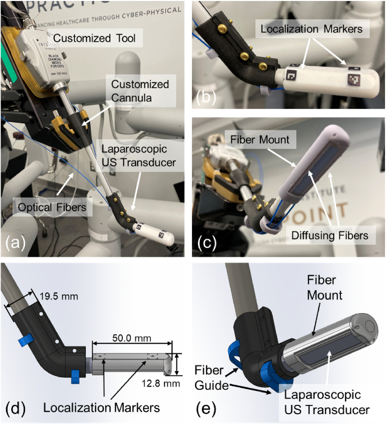
To perform PA imaging using the da Vinci surgical system, a customized laparoscopic PA imaging probe was utilized. A side-shooting US probe (Philips ATL Lap L9-5, Philips, Netherlands) was used as the PA signal receiver. The probe has 128 channels with a central frequency of 7 MHz (bandwidth: 5 MHz to 9 MHz). To generate PA signals, two customized side-illumination diffusing optical fibers (FT600EMT, Thorlabs, USA) were mounted to the two sides of the US transducer via the fiber mount and the fiber guide (see Fig. 1 (c)-(e)). The customized fibers were created by partially removing the fiber cladding and chemically etching the silicon core. This process enabled the fibers to provide side-illumination [34]. The fiber mount had a side window for receiving PA signal. Its two fiber traversing tunnels allowed the fiber to emit laser towards the tissue while keeping it parallel to the longitudinal axis of the US transducer. The fiber guide prevented laser dissipation due to excessive fiber bending. Such configuration of a PA imaging device allows miniaturization of the device while maintaining effective PA image quality [34]. A laser system (Phocus MOBILE, OPOTEK, USA) capable of emitting wavelength-tunable laser (from 690 to 950 nm) at a repetition rate of 20 Hz with 5 ns pulse duration was used as a light source. The Verasonics Vantage system (Vantage 128, Verasonics, USA) was used to acquire and process the PA signals to generate real-time two-dimensional (2D) PA images.
Fig. 1.
(a) The customized laparoscopic photoacoustic (PA) probe compatible with the da Vinci System. (b) The localization markers on the fiber mount. (c) The imaging tip of the probe with two side-illumination diffusing fibers attached by the mount. (d) and (e) The Computer-Aided Design (CAD) design of the customized laparoscopic PA probe compatible with the da Vinci system and the design dimension.
As shown in Fig. 1 (a), we modified a da Vinci research kit (dVRK, Intuitive Foundation, USA) [35] tool and mounted it on one of the patient side manipulator (PSM) to integrate the aforementioned PA probe with the da Vinci surgical platform (da Vinci Surgical System (Standard), Intuitive, USA). The cannula on the PSM was redesigned and fabricated to accommodate the 10 mm diameter of the US probe (as a standard forceps tool has an 8 mm diameter). Finally, four ArUco markers arranged symmetrically about the longitudinal axis of the transducer were engraved on the fiber mount, opposing to its side window. These markers were used to estimate the 3D spatial transformation between the PA probe and the endoscopic camera mounted on the endoscopic camera manipulator (ECM) [36], which enables the localization of the PA probe during imaging, as well as projecting the PA functional information into the surgical scene.
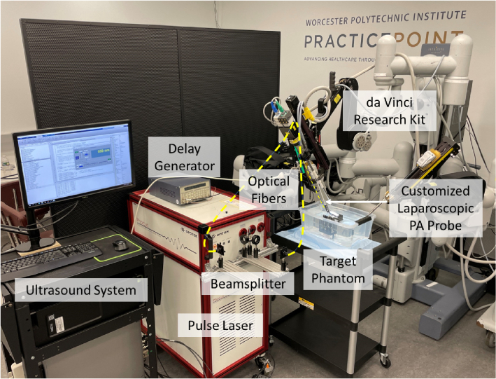
Our da Vinci integrated PA probe can be manipulated by the PSM with two rotational degree-of-freedom (DoF) and one translational DoF, as well as the inherent remote center of motion (RCM) functionality [37]. This allows safe and large-area PA imaging during the surgery procedure. The PSM was mounted on the setup joints (SUJ) of the da Vinci surgical system. The fully integrated system can be seen in Fig. 2.
Fig. 2.
Device overview of the proposed photoacoustic (PA) imaging integrated da Vinci surgical platform.
2.2. Volumetric PA data generation
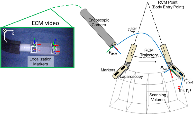
In order to project functional information that reveals the vasculature under the tissue surface into the endoscopic view for surgical guidance, a sweeping motion of the PA probe is programmed to acquire volumetric PA data that covers a large area in the surgical scene. Cross-sectional PA images were uniformly sampled along the probe trajectory, which was then compounded into a 3D volume using the tracked probe poses at each imaging location. As illustrated in Fig. 3, the PA probe swept on an RCM fan-shape trajectory, with the RCM center located at the PSM’s body entry point. In the meantime, a total number of frames PA images were discretely sampled at fixed angular intervals. We assume the centroids of the ArUco markers are co-planar, and the rigid body transformation between the arbitrary marker and is known from the PA probe’s Computer-Aided Design (CAD) modeling. Therefore, at the -th PA image acquisition point, the transformation from to can be derived when at least one marker was captured in the endoscopic view. The marker’s pose was estimated using OpenCV’s ArUco marker detection API [38]. Multiple markers were able to be detected under most circumstances, where was then an average of all possible derived by the -th detected marker. Additionally, a temporal averaging filter with a window size of ten timestamps was applied at each acquisition point to reduce the chance of getting an outlier . Lastly, an arc was fitted to the previous -1 probe poses (i.e., ) in the RCM plane using the method in [39] to obtain a smoothed historical probe trajectory (i.e., ). The z-axis of (see Fig. 3) on the smoothed trajectory was resampled to be the tangential direction at each fitted acquisition point, whereas the x-axis was resampled to be the radial direction. Next, the PA volume was generated by transforming all PA images into a common coordinate, . For each pixel in the -th PA image, its spatial location under can be determined since the physical size of the pixel was known. was then transformed into using Eq. (1):
| (1) |
where is the transformed pixel position. All pixel positions were augmented to be homogeneous with the transformation matrices before multiplication. The volume data, denoted as , is stored in the form of a 3D matrix by discretizing the transformed pixel positions under . To better evaluate the accuracy of the volumetric data, later on in section C, we will use maximum intensity projection (MIP) which keeps the highest-intensity pixels in the camera depth direction of , to visualize , hence compressing the 3D volume into a 2D image. Note that each pixel in the acquired data is represented in Cartesian coordinates with respect to the imaging probe. The localization marker used for registration was also detected by the camera in Cartesian coordinates. This ensures that all the subsequent processing steps, including the conversion to volumetric imaging and the MIP by taking the maximum intensities along each column, are performed in the Cartesian coordinate system.
Fig. 3.
Scanning trajectory and the coordinate frame assignment for the photoacoustic (PA) augmented surgical scene rendering. The endoscopic camera manipulator (ECM) image displays the detected localization markers and the defined ECM frame.
2.3. PA-augmented surgical scene rendering
During the process of PA tomography scanning using the sweeping probe motion, the trajectory smoothing of the RCM, PA volume generation, and the surgical scene rendering can be performed in parallel, hence realizing a quasi-real-time surgical scene augmentation. The PA functional information was extracted from the PA volume and rendered into the endoscopic view for surgical guidance. To create the rendering, the spatially localized PA volume can be resampled based on the surgical needs and overlaid into the endoscopic view via perspective projection. Without loss of generality, here we explain the method to render the MIP into the endoscopic view. Functional information from other perspectives, such as tissue tomography, can be rendered following a similar principle. To generate MIP, we first search for the voxels with the highest intensity in in the camera depth direction, where n is the total number of voxels. Projecting into the endoscopic view yields a 2D image whose pixel positions, , can be calculated via Eq. (2):
| (2) |
where is the intrinsic matrix of the endoscopic camera which was calibrated using a checkerboard [40] beforehand; is the scaling factor. Finally, the PA overlaid endoscopic view image is generated through Eq. (3)
| (3) |
where adjusts the transparency of by multiplying a factor to pixels below an empirically set intensity threshold onto the original endoscopic image . The value of 0 denotes complete transparency, while 1 represents non-transparency. In this study, the transparency level is set as 0.5.
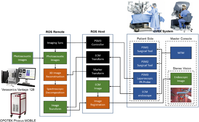
The da Vinci platform is driven by Robot Operating System (ROS). The endoscopic camera detected marker position was streamed to the US system (see Fig. 4) via ROS topic communication using the same pipeline in [41] to enable real-time rendering. The ROS host runs on the dVRK PC, overseeing the motion of the PSM, ECM motion, mapping of inputs from the surgeon console, as well as the streaming and display of ECM stereo vision. The US machine is connected to ROS as a remote port. The PA probe is actuated by PSM3 under the control of the ROS host, while its imaging data is recorded on the US machine. The reconstructed volumetric PA image denoted by can then be generated on the US system and sent back to the da Vinci host via ROS topic publication. After overlaying MIP image on the endoscopic camera image, the PA-augmented scene can be streamed to the master console and displayed to the surgeon.
Fig. 4.
Communication architecture of the proposed framework.
3. Experimental implementation
3.1. Phantom study
Prior to integrating the PA-augmented feedback with the ECM image, a wire phantom study was conducted to validate the capability of the customized probe to perform PA tomography actuated by the robot, as well as evaluate the accuracy of the image reconstruction of the volumetric PA tomography. A tomography scanning was performed with the PA probe actuated by the da Vinci robot. A two-layer nylon fish wire phantom with a pattern was used as the imaging target. The wire had a diameter of 0.2 mm. The probe scanned a 40 degrees imaging range with the pitch of a 1-degree step. The previously introduced fan-shaped tomography was performed with a fan radius of 27 mm. At each scanning location, an averaging filter with the size of 128 frames was applied to enhance imaging contrast. The PA excitation of 700 nm was selected. The US image at the identical spatial position was also obtained for comparative analysis. Both acquired PA/US signal was beamformed by the conventional Delay-and-Sum (DAS) algorithm [42]. The pose of the probe was recorded at each scanning step based on the detected marker data for 3D reconstruction. By selecting the intersection points of the wire phantom as targets, the target registration error (TRE) [43] was computed between the 3D reconstructed PA image and the actual phantom measurement to evaluate the 3D reconstruction accuracy of the image using the registration method described in [44]. The registration was performed by solving the minimization of the per-target spatial distance using the singular value decomposition (SVD) based least-squares approach. The optimization goal is illustrated in Eq. (4).
| (4) |
where is the objective function to be minimized. and are the targets’ coordinates measured from the PA volume and the actual phantom with a total number of targets. and are the rotation matrix and the translation vector to be solved. The computed TRE value is the root mean square error (RMSE) Euclidean distance between the two registered markers.
3.2. Ex vivo validation of PA-augmented surgical guidance
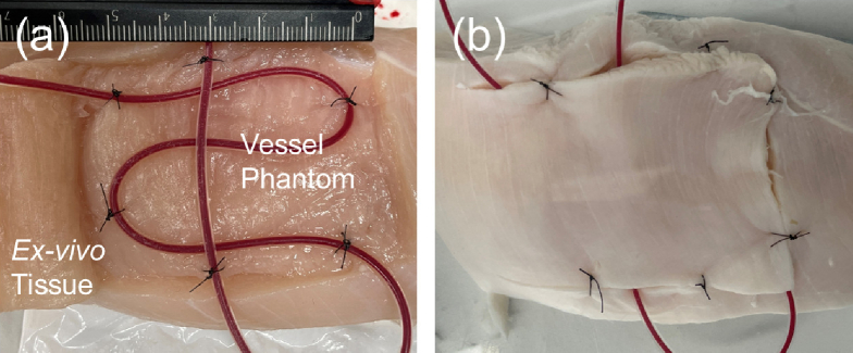
The proposed real-time framework for PA-augmented surgical scene rendering was validated through an ex vivo study. In this study, a tube-vessel phantom was scanned by the da Vinci actuated PA tomography to demonstrate the feedback of vascular mapping projected onto the ECM image. The vessel-mimicking phantom was designed with silicon tubes (inner diameter: 1 mm, outer diameter: 2 mm) placed in the grocery chicken breast tissue sample, as shown in Fig. 5. The tube was injected with heparinized porcine blood (Porcine Whole Blood, Innovative Research, USA) with Na Heparin anticoagulant and was covered with a layer of tissue with an approximate thickness of 10 mm. The prepared phantom was submerged in water for the scanning.
Fig. 5.
Ex vivo vessel-mimicking phantom design. (a) shows the buried tube filled with blood and (b) shows the sutured tissue prepared for scanning.
The laparoscopic PA probe was initially aligned with the phantom surface above the vessel region, followed by an autonomous sweeping motion. A fan-shaped tomography was performed with a 40-degree range at a 1-degree pitch, and an averaging filter with the size of 128 frames was implemented at each scanning step to enhance the imaging contrast. The wavelength of 850 nm was selected for PA scanning to maximize the PA signal generated from oxygenated hemoglobin in the blood. The acquired PA image was beamformed by the DAS algorithm.
To further evaluate the accuracy of the PA-augmented vascular map rendering, the reconstructed geometry of the phantom was scanned and cross-validated with a 3D cone-beam computed tomography (CB-CT) scanning image, and the sample measurement that was performed before the PA scanning. A C-arm CB-CT (ARCADIS Orbic, Siemens Healthineers, Germany) was used to image the ex vivo sample after the PA scanning to acquire 3D geometry ground truth of the vessel phantom. The vessel in each imaging modality was labeled and compared to evaluate the accuracy of the 3D reconstruction. The iterative closest point (ICP) algorithm [45] was selected to register the labeled point cloud between PA and CB-CT imaging. While the method in [44] provides a closed-form registration solution for TRE evaluation, it is required first to identify corresponding fiducial points, e.g., the wiring intersections in the phantom study, between different imaging modalities, which is challenging for the vascular phantom in our ex vivo experiment setup. On the other hand, ICP iteratively estimates the point cloud transformation by minimizing the same objective function (Eq. (4)), yet without imposing the constraint of known fiducial correspondences. Given this, we selected to use the RMSE between the ICP registered points to assess the imaging accuracy in the ex vivo study.
4. Results
4.1. Phantom study
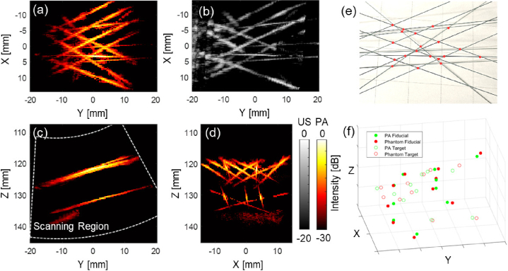
A Phantom study was conducted to validate the imaging function of the customized device and quantify the accuracy of the volumetric reconstruction with our proposed framework. Figure 6 shows the result of the wire phantom study. The phantom wires were clearly captured after beamforming with a two-layer structure visible. The reconstructed PA phantom shape matches with ground truth shown volumetric US image. The result validated the imaging capability of the PA probe actuated by the da Vinci robot. The wire phantom was reconstructed based on the recorded PA probe pose localized by the markers to match each 2D PA image to the ECM frame, as discussed in the method section. Each pixel in the 2D PA image was computed and mapped to the corresponding 3D voxel position. The MIP images were displayed from various perspectives to demonstrate the reconstructed volumetric PA images. The designed phantom pattern was recovered after image reconstruction.
Fig. 6.
The 3D reconstructed wire phantom photoacoustic (PA) image based on the endoscopic frame. (a) shows the maximum intensity projection (MIP) of the reconstructed PA image across the entire depth range. (b) shows the reconstructed ultrasound (US) image with same viewpoint as (a). (c) shows the MIP image from the Y-Z plane with the white line indicating scanning region, and (d) from X-Z plane. (e) shows the top-view photo of the phantom and the red points indicate the marker location for the reconstruction error calculations. (f) shows the marker point location error that occurred during the reconstruction scanning.
To quantitatively evaluate the accuracy of the 3D image reconstruction based on the da Vinci actuation, 20 points-of-interest located on both layers of the phantom were labeled in the volumetric PA image with their corresponding locations on the actual phantom. These points were marked at the intersection point between two wires to improve localization accuracy. All the intersecting points among a total of 14 wires, which were distinctly captured in the 3D PA image, were identified as points-of-interest. 10 points were selected as fiducial in registering the PA image to the actual phantom. The points were selected randomly within each layer while maintaining a ratio close to 1:1 between fiducial and TRE computing points. The TRE was computed based on the remaining 10 points. The TRE was computed between the two sets of markers, resulting in an error of between the PA image and the phantom.
4.2. Ex vivo validation of PA-augmented surgical guidance
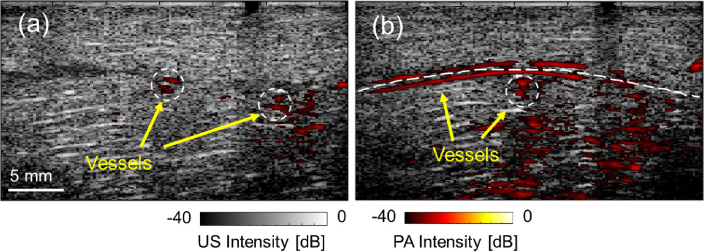
The ex vivo study was conducted to confirm the efficacy of our proposed framework for rendering PA-detected vasculature in real-time during surgical procedures. The vascular-mimicking tube phantom, implanted in the chicken breast tissue, was detected with the customized laparoscopic PA probe actuated by da Vinci robot. The PA images at each scanning location successfully highlighted the vascular contrast beneath the tissue surface. Figure 7 demonstrates the PA images obtained during scanning, overlaid with the US image acquired at the same location. In the images, both vessels perpendicular and parallel to the scanning direction were detected.
Fig. 7.
The ex vivo study result. (a) and (b) show the photoacoustic (PA) images at two scanning locations highlighting the vascular structure overlaid with the corresponding ultrasound (US) images collected at the same location.
For each scanning step, the PA imaging location was computed based on the relative pose between the imaging probe and the ECM, using the detected markers in the video stream. Each slice of the 2D PA image can then be rotated and mapped to the corresponding pixel location on the video frame. Figure 8 (a) presents the PA-augmented ECM videoscopic image based on our proposed framework. The operating field is clearly visible in the image frame, with two common surgical instruments on either side of the imaging field of view. The customized laparoscopic PA probe is in the center of the field, with markers captured and their pose detected in the pixel frame. The transformation of the PA image was computed, and the image was projected onto the video stream based on the camera parameter. During the tomography scanning, the location of the previously detected feature can be recorded and rendered in the video as well to provide surgical guidance to avoid injuring vessels. Figure 8 (b) shows the volumetric PA images projected onto the ECM image after the scanning. Three vessel tubes were captured with their location matched with the phantom design. The highlighted vasculature was displayed using depth encoding color with respect to the ECM viewpoint, thereby facilitating the surgeon’s enhanced comprehension of the anatomical structure. The detected vessel location on the 2D PA image matched with the exposing tubes captured on the image.
Fig. 8.
(a) The real-time photoacoustic-augmented surgical scene displayed to the da Vinci master console. (b) The maximum intensity projection (MIP) of the reconstructed volumetric PA images of vasculature overlaid the da Vinci endoscopic camera manipulator (ECM) image in depth encoding color. The depth is computed with respect to the ECM viewpoint. (see Visualization 1 (38.9MB, mp4) )
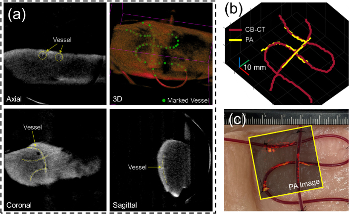
The vessel trajectory observed in the volumetric PA image was cross-validated using CB-CT imaging to quantify the precision of the reconstruction. The PA-detected vessels were identified and marked in the volumetric space. A 3D CB-CT image of the sample was reconstructed and shown in Fig. 9 (a), where the vessel tubes were detected and labeled in 3D space. The labeled point set obtained from both imaging modalities was registered utilizing the ICP algorithm and displayed in Fig. 9 (b). The RMSE between the registered nearest point sets was calculated as 1.247 mm, with point sets having a resolution of 1 mm. A total number of 104 points were used for the quantification. The top view MIP image of the reconstructed PA scan was overlaid with the sample picture captured prior to the scan, as presented in Fig. 9 (c). The reconstructed shape of the three vessel-mimicking tubes matched the appearance of the sample picture prior to scanning.
Fig. 9.
(a) 3D cone-beam computed tomography (CB-CT) scanning of the ex vivo sample after the study. The yellow dashed line indicates the detected vessels. The green dots label the detected vessel trajectory. (b) Reconstructed 3D vessel trajectory from CB-CT imaging and proposed photoacoustic (PA) scanning. (c) Actual sample picture before scanning overlaid with the maximum intensity projection (MIP) image of the PA scanning.
5. Discussion
The proposed da Vinci integrated framework was evaluated in a wire phantom study. Two layers of the phantom were captured in the scanning. The customized PA imaging device is capable of penetrating more than 25 mm in the water medium with the side-illumination diffusing fibers. The designed phantom pattern was restored in the PA image based on the probe location calculated by the recorded marker information during the scanning. The intensity of the wire shows a decline from the center to the edge which is caused by the intersecting angle between the wire and the imaging plane reducing the elevational focus. The 3D reconstruction error was calculated as in an approximately 40 mm by 35 mm scanning area covered by the transducer. Although the accuracy of the visual tracking marker has been optimized to approximately 1 mm in our application, the recorded trajectory was noisy during the 3D reconstruction of a sub-millimeter resolution PA image. As a result, we applied trajectory smoothing in our presented results. An imaging feature-based reconstruction smoothing method should be investigated in future work.
The ex vivo validation successfully demonstrated the real-time PA-augmented surgical scene rendering in the da Vinci console. The laparoscopic PA probe successfully scanned a vessel-mimicking phantom, highlighting the vessels with the PA image. The existence of the tubes at the PA highlighted location was confirmed by the US image, which justified the captured PA contrast generated by the blood. The simulated vessels were detected regardless of their intersection angle with the imaging place. The vascular location shown in the MIP image matches the sample design, as well as the 3D CB-CT scanning. The vessel trajectory reconstructed using both imaging modalities aligns. The reconstruction RMSE of 1.247 mm corresponds to the reconstruction error observed in the phantom study (1.20 mm). Although precautions were taken during the experiment, the quantification results between CB-CT and PA imaging may be susceptible to inaccuracies due to potential vessel shifting. Additionally, the registration error was assessed based on a point cloud with a resolution of 1 mm, potentially underestimating the presence of millimeter-level noise. In addition, it is noteworthy that the vessel phantom design traverses various depths in relation to the transducer. This constraint has the potential to influence the accuracy assessment. To address these concerns and enhance the evaluation, adopting a multilayer vascular phantom would yield more comprehensive point cloud data across a diverse range of depths.
The direct PA image feedback in the da Vinci image console was presented in real-time through the proposed framework. The PA image was transformed and rotated according to the real-time detection of the markers on top of the imaging device, and then overlaid in the correct location with the intuitive projection angle to the camera viewpoint. The utilization of a depth encoding colormap further enables an intuitive comprehension of the anatomical structure. Additionally, the result also includes the surgical tools in the field of view placed in a position that is not subject to cause injury without any interference from the PA scanning. This further demonstrates the feasibility of integrating PA guidance in the RAS with our proposed framework.
Although the result successfully demonstrated the proposed frame in terms of providing real-time PA augmentation in the da Vinci console for better surgical guidance, there are several limitations to the current system. First, the customized laparoscopic PA probe was currently designed with an angled tip. This design simplified the kinematic calculation for localizing PA image location in the ECM video image. However, the clinical viability of the current design is met with challenges, particularly during the insertion of surgical tools, due to the presence of the bulky customized fiber mount. Addressing this concern can be accomplished by employing a thinner material that provides comparable functionality to the current design, encompassing fiber constraining and marker localization while simultaneously reducing the diameter of the tool. Additional tip actuation should be developed in future work. In addition, the current setup does not grant co-locating functional PA information with surgical tools in that the precise distance between the vessels and the tools cannot be assessed. Although the display mapped the distance of the vasculature relative to the camera viewpoint, the incorporation of a robotic controller capable of automatic image-tool alignment, facilitating tool-following imaging, and providing tool-to-vessel distance information, would significantly enhance the practicality and usability of our proposed system. Second, the presented study was performed in the water medium for acoustic coupling between the tissue and the imaging transducer. Reproducing this acoustic coupling in the actual space-constrained laparoscopic environment could be challenging at the current stage. Finally, the current PA imaging pipeline suffers from low framerate due to the large window size (128 frames) averaging filter to enhance imaging contrast. Increasing the imaging speed requires improving the SNR with less data duration. Advanced beamformers, such as short-lag spatial coherence [46], synthetic-aperture-based PA re-beamforming [47], and deep learning-based beamforming [48] are recognized for yielding a comparable SNR with a reduced number of frames required. Furthermore, a high-speed laser with 100 Hz [49] or higher pulse repetition frequency can increase the data points and shorten the data recording time. Other cost-effective design optimizations could also be explored as part of future investigation [50].
6. Conclusions
This work integrated a real-time laparoscopic PA imaging framework into the da Vinci surgical system. The framework overlays real-time PA imaging information with the endoscopic view based on the vision tracking, and enables the formulation of 3D PA imaging with a wide ROI. The wire phantom study demonstrated the 3D reconstruction accuracy of quantified by TRE. The phantom study by embedding blood-filled tubes into the chicken breast demonstrates successful real-time vessel visualization. These results suggest that the proposed framework could provide anatomical and functional feedback to surgeons in real-time and it has the potential to be incorporated into RAS.
Acknowledgment
This work was supported by the Worcester Polytechnic Institute Transformative Research and Innovation, Accelerating Discovery (TRIAD); National Institutes of Health under grants CA134675, DK133717, OD028162; and National Science Foundation AccelNet Grant 1927275.
Funding
National Science Foundation10.13039/100000001 (AccelNet Grant 1927275); Worcester Polytechnic Institute Transformative Research and Innovation, Accelerating Discovery (TRIAD); National Institutes of Health10.13039/100000002 (CA134675, DK133717, OD028162).
Disclosures
The authors declare no conflicts of interest.
Data Availability
Data underlying the results presented in this paper are not publicly available at this time but may be obtained from the authors upon reasonable request.
References
- 1.Long Q., Guan B., Mu L., Tian J., Jiang Y., Bai X., Wu D., “Robot-assisted radical prostatectomy is more beneficial for prostate cancer patients: A system review and meta-analysis,” Med. Sci. Monit. 24, 272–287 (2018). 10.12659/MSM.907092 [DOI] [PMC free article] [PubMed] [Google Scholar]
- 2.Zhang L., Ma J., Zang L., Dong F., Lu A., Feng B., He Z., Hong H., Zheng M., “Prevention and management of hemorrhage during a laparoscopic colorectal surgery,” Ann. Laparosc. Endosc. Surg 1, 40 (2016). 10.21037/ales.2016.11.22 [DOI] [Google Scholar]
- 3.Novellis P., Jadoon M., Cariboni U., Bottoni E., Pardolesi A., Veronesi G., “Management of robotic bleeding complications,” Ann. Cardiothorac. Surg. 8(2), 292–295 (2019). 10.21037/acs.2019.02.03 [DOI] [PMC free article] [PubMed] [Google Scholar]
- 4.Garry R., “Complications of laparoscopic entry,” Gynaecological Endoscopy 6(6), 319–329 (2003). 10.1111/j.1365-2508.1997.151-gy0558.x [DOI] [Google Scholar]
- 5.Asfour V., Smythe E., Attia R., “Vascular injury at laparoscopy: a guide to management,” Journal of Obstetrics and Gynaecology 38(5), 598–606 (2018). 10.1080/01443615.2017.1410120 [DOI] [PubMed] [Google Scholar]
- 6.Beard P., “Biomedical photoacoustic imaging review,” Interface Focus. 1(4), 602–631 (2011). 10.1098/rsfs.2011.0028 [DOI] [PMC free article] [PubMed] [Google Scholar]
- 7.Gandhi N., Allard M., Kim S., Kazanzides P., Bell M. A. L., “Photoacoustic-based approach to surgical guidance performed with and without a da vinci robot,” 22, 121606 (2017). 10.1117/1.JBO.22.12.12160 [DOI] [Google Scholar]
- 8.Yao J., Wang L. V., “Photoacoustic microscopy,” Laser & Photonics Reviews 7(5), 758–778 (2013). 10.1002/lpor.201200060 [DOI] [PMC free article] [PubMed] [Google Scholar]
- 9.Matsumoto Y., Asao Y., Sekiguchi H., Yoshikawa A., Ishii T., ichi Nagae K., Kobayashi S., Tsuge I., Saito S., Takada M., Ishida Y., Kataoka M., Sakurai T., Yagi T., Kabashima K., Suzuki S., Togashi K., Shiina T., Toi M., “Visualising peripheral arterioles and venules through high-resolution and large-area photoacoustic imaging,” Sci. Rep. 8(1), 14930–11 (2018). 10.1038/s41598-018-33255-8 [DOI] [PMC free article] [PubMed] [Google Scholar]
- 10.Matsumoto Y., Asao Y., Yoshikawa A., Sekiguchi H., Takada M., Furu M., Saito S., Kataoka M., Abe H., Yagi T., Togashi K., Toi M., “Label-free photoacoustic imaging of human palmar vessels: a structural morphological analysis,” Sci Rep 8(1), 786 (2018). 10.1038/s41598-018-19161-z [DOI] [PMC free article] [PubMed] [Google Scholar]
- 11.Hu S., “Neurovascular photoacoustic tomography,” Frontiers in Neuroenergetics (2010). 10.3389/fnene.2010.00010 [DOI] [PMC free article] [PubMed]
- 12.Hu S., Wang L. V., “Photoacoustic imaging and characterization of the microvasculature,” J. Biomed. Opt. 15(1), 011101 (2010). 10.1117/1.3281673 [DOI] [PMC free article] [PubMed] [Google Scholar]
- 13.Kim C., Favazza C., Wang L. V., “In vivo photoacoustic tomography of chemicals: High-resolution functional and molecular optical imaging at new depths,” Chem. Rev. 110(5), 2756–2782 (2010). 10.1021/cr900266s [DOI] [PMC free article] [PubMed] [Google Scholar]
- 14.Gao S., Mansi T., Halperin H. R., Zhang H. K., “Photoacoustic necrotic region mapping for radiofrequency ablation guidance,” (IEEE, 2021), pp. 1–4. [Google Scholar]
- 15.Graham M., Assis F., Allman D., Wiacek A., Gonzalez E., Gubbi M., Dong J., Hou H., Beck S., Chrispin J., Bell M. A., “In vivo demonstration of photoacoustic image guidance and robotic visual servoing for cardiac catheter-based interventions,” IEEE Trans. Med. Imaging 39(4), 1015–1029 (2020). 10.1109/TMI.2019.2939568 [DOI] [PubMed] [Google Scholar]
- 16.Graham M., Assis F., Allman D., Wiacek A., Gonzalez E., Michelle A., Graham T., Gubbi M. R., Dong J., Hou H., Beck S., Chrispin J., Bell M. A. L., “Photoacoustic image guidance and robotic visual servoing to mitigate fluoroscopy during cardiac catheter interventions,” Advanced Biomedical and Clinical Diagnostic and Surgical Guidance Systems XVIII 11229, 45–85 (2020). 10.1117/12.2546910 [DOI] [Google Scholar]
- 17.Zhang H. K., Chen Y., Kang J., Lisok A., Minn I., Pomper M. G., Boctor E. M., “Prostate-specific membrane antigen-targeted photoacoustic imaging of prostate cancer in vivo,” J. Biophotonics 11(9), 1–6 (2018). 10.1002/jbio.201800021 [DOI] [PMC free article] [PubMed] [Google Scholar]
- 18.Mehrmohammadi M., Yoon S. J., Yeager D., Emelianov S. Y., “Photoacoustic imaging for cancer detection and staging,” Curr Mol Imaging 2(1), 89–105 (2013). 10.2174/2211555211302010010 [DOI] [PMC free article] [PubMed] [Google Scholar]
- 19.Zhang J., Duan F., Liu Y., Nie L., “High-resolution photoacoustic tomography for early-stage cancer detection and its clinical translation,” Radiology: Imaging Cancer 2(3), e190030 (2020). 10.1148/rycan.2020190030 [DOI] [PMC free article] [PubMed] [Google Scholar]
- 20.Allard M., Shubert J., Bell M. A. L., “Feasibility of photoacoustic-guided teleoperated hysterectomies,” J. Med. Imag. 5(02), 1 (2018). 10.1117/1.JMI.5.2.021213 [DOI] [PMC free article] [PubMed] [Google Scholar]
- 21.Wiacek A., Wang K. C., Wu H., Bell M. A., “Photoacoustic-guided laparoscopic and open hysterectomy procedures demonstrated with human cadavers,” IEEE Trans. Med. Imaging 40(12), 3279–3292 (2021). 10.1109/TMI.2021.3082555 [DOI] [PubMed] [Google Scholar]
- 22.Moradi H., Tang S., Salcudean S. E., “Toward robot-assisted photoacoustic imaging: Implementation using the da vinci research kit and virtual fixtures,” IEEE Robot. Autom. Lett. 4(2), 1807–1814 (2019). 10.1109/LRA.2019.2897168 [DOI] [Google Scholar]
- 23.Moradi H., Tang S., Salcudean S. E., “Toward intra-operative prostate photoacoustic imaging: Configuration evaluation and implementation using the da vinci research kit,” IEEE Trans. Med. Imaging 38(1), 57–68 (2019). 10.1109/TMI.2018.2855166 [DOI] [PubMed] [Google Scholar]
- 24.Song H., Jiang B., Xu K., Wu Y., Taylor R. H., Deguet A., Kang J. U., Salcudean S. E., Boctor E. M., “Real-time intraoperative surgical guidance system in the da vinci surgical robot based on transrectal ultrasound/photoacoustic imaging with photoacoustic markers: an ex vivo demonstration,” IEEE Robotics and Automation Letters, (2022). [DOI] [PMC free article] [PubMed] [Google Scholar]
- 25.Wang H., Liu S., Wang T., Zhang C., Feng T., Tian C., “Three-dimensional interventional photoacoustic imaging for biopsy needle guidance with a linear array transducer,” J. Biophotonics 12(12), e201900212 (2019). 10.1002/jbio.201900212 [DOI] [PubMed] [Google Scholar]
- 26.Shi M., Zhao T., West S. J., Desjardins A. E., Vercauteren T., Xia W., “Improving needle visibility in led-based photoacoustic imaging using deep learning with semi-synthetic datasets,” Photoacoustics 26, 100351 (2022). 10.1016/j.pacs.2022.100351 [DOI] [PMC free article] [PubMed] [Google Scholar]
- 27.Shubert J., Bell M. A., “Photoacoustic based visual servoing of needle tips to improve biopsy on obese patients,” IEEE International Ultrasonics Symposium, IUS (2017). [Google Scholar]
- 28.Bell M. A. L., Shubert J., “Photoacoustic-based visual servoing of a needle tip,” Scientific Reports 2018 8:1 8, 1–12 (2018). 10.1038/s41598-018-33931-9 [DOI] [PMC free article] [PubMed] [Google Scholar]
- 29.Ansari R., Zhang E. Z., Desjardins A. E., Beard P. C., “All-optical forward-viewing photoacoustic probe for high-resolution 3D endoscopy,” Light Sci Appl 7(1), 75 (2018). 10.1038/s41377-018-0070-5 [DOI] [PMC free article] [PubMed] [Google Scholar]
- 30.Guo H., Li Y., Qi W., Xi L., “Photoacoustic endoscopy: A progress review,” J. Biophotonics 13(12), e202000217 (2020). 10.1002/jbio.202000217 [DOI] [PubMed] [Google Scholar]
- 31.Zhang H. K., Aalamifar F., Kang H. J., Boctor E. M., “Feasibility study of robotically tracked photoacoustic computed tomography, Proceedings: Medical imaging 2015: ultrasonic imaging and tomography” 9419, 31–37 (2015). 10.1117/12.2084600 [DOI] [Google Scholar]
- 32.Xing B., He Z., Zhou F., Zhao Y., Zhao Y., Shan T., Shan T., Shan T., “Automatic force-controlled 3d photoacoustic system for human peripheral vascular imaging,” Biomed. Opt. Express 14(2), 987–1002 (2023). 10.1364/BOE.481163 [DOI] [PMC free article] [PubMed] [Google Scholar]
- 33.Gao S., Wang Y., Zhou H., Yang K., Jiang Y., Lu L., Wang S., Ma X., Nephew B. C., Fichera L., Fischer G. S., Zhang H. K., “Laparoscopic photoacoustic imaging system integrated with the da Vinci surgical system,” in Medical Imaging 2023: Image-Guided Procedures, Robotic Interventions, and Modeling , Vol. 12466 Linte C. A., Siewerdsen J. H., eds., International Society for Optics and Photonics (SPIE, 2023), p. 1246609. [Google Scholar]
- 34.Gao S., Li M., Wang Y., Shen Y., Flegal M. C., Nephew B. C., Fischer G. S., Liu Y., Fichera L., Zhang H. K., “Laparoscopic photoacoustic imaging system based on side-illumination diffusing fibers,”IEEE Transactions on Biomedical Engineering, (IEEE, 1–10 (2023). [DOI] [PMC free article] [PubMed] [Google Scholar]
- 35.Kazanzidesf P., Chen Z., Deguet A., Fischer G. S., Taylor R. H., Dimaio S. P., “An open-source research kit for the Da Vinci surgical system,”Proceedings - IEEE International Conference on Robotics and Automation, pp.6434–6439 (2014). [Google Scholar]
- 36.Ma X., Zhang Z., Zhang H. K., “Autonomous scanning target localization for robotic lung ultrasound imaging,”IEEE International Conference on Intelligent Robots and Systems, pp.9467–9474 (2021). [DOI] [PMC free article] [PubMed] [Google Scholar]
- 37.Kuo C.-H., Dai J. S., “Robotics for minimally invasive surgery: A historical review from the perspective of kinematics,”International Symposium on History of Machines and Mechanisms, pp.337–354 (2009). [Google Scholar]
- 38.Bradski G., “The opencv library.,” Dr. Dobb’s journal: software tools for the professional programmer. 25, 120–123 (2000). [Google Scholar]
- 39.Pratt V., “Direct least-squares fitting of algebraic surfaces,” SIGGRAPH Comput. Graph. 21(4), 145–152 (1987). 10.1145/37402.37420 [DOI] [Google Scholar]
- 40.Zhang Z., “A flexible new technique for camera calibration,” IEEE Trans. Pattern Anal. Machine Intell. 22(11), 1330–1334 (2000). 10.1109/34.888718 [DOI] [Google Scholar]
- 41.Ma X., Kuo W.-Y., Yang K., Rahaman A., Zhang H. K., “A-see: Active-sensing end-effector enabled probe self-normal-positioning for robotic ultrasound imaging applications,” IEEE Robot. Autom. Lett. 7(4), 12475–12482 (2022). 10.1109/LRA.2022.3218183 [DOI] [PMC free article] [PubMed] [Google Scholar]
- 42.Gao S., Tsumura R., Vang D. P., Bisland K., Xu K., Tsunoi Y., Zhang H. K., “Acoustic-resolution photoacoustic microscope based on compact and low-cost delta configuration actuator,” Ultrasonics 118, 106549 (2022). 10.1016/j.ultras.2021.106549 [DOI] [PMC free article] [PubMed] [Google Scholar]
- 43.Fitzpatrick J. M., West J. B., “The distribution of target registration error in rigid-body point-based registration,” IEEE Trans. Med. Imaging 20(9), 917–927 (2001). 10.1109/42.952729 [DOI] [PubMed] [Google Scholar]
- 44.Arun K. S., Huang T. S., Blostein S. D., “Least-squares fitting of two 3-d point sets,” IEEE Trans. Pattern Anal. Mach. Intell. PAMI-9(5), 698–700 (1987). 10.1109/TPAMI.1987.4767965 [DOI] [PubMed] [Google Scholar]
- 45.Sinko M., Kamencay P., Hudec R., Benco M., “3d registration of the point cloud data using icp algorithm in medical image analysis,” in ELEKTRO, (2018), pp. 1–6. [Google Scholar]
- 46.Bell M. A., Xiaoyu G., Kang H. J., Boctor E., “Improved contrast in laser-diode-based photoacoustic images with short-lag spatial coherence beamforming,” IEEE International Ultrasonics Symposium, IUS, pp37–40 (2014). [Google Scholar]
- 47.Zhang H. K., Bell M. A. L., Guo X., Kang H. J., Boctor E. M., “Synthetic-aperture based photoacoustic re-beamforming (spare) approach using beamformed ultrasound data,” Biomed. Opt. Express 7(8), 3056 (2016). 10.1364/BOE.7.003056 [DOI] [PMC free article] [PubMed] [Google Scholar]
- 48.Allman D., Reiter A., Bell M. A., “Photoacoustic source detection and reflection artifact removal enabled by deep learning,” IEEE Trans. Med. Imaging 37(6), 1464–1477 (2018). 10.1109/TMI.2018.2829662 [DOI] [PMC free article] [PubMed] [Google Scholar]
- 49.Lim H. G., Jung U., Choi J. H., Choo H. T., Kim G. U., Ryu J., Choi H., “Fully customized photoacoustic system using doubly q-switched nd:yag laser and multiple axes stages for laboratory applications,” Sensors 22(7), 2621 (2022). 10.3390/s22072621 [DOI] [PMC free article] [PubMed] [Google Scholar]
- 50.Wiacek A., Bell M. A. L., “Photoacoustic-guided surgery from head to toe [invited],” Biomed. Opt. Express 12(4), 2079–2117 (2021). 10.1364/BOE.417984 [DOI] [PMC free article] [PubMed] [Google Scholar]
Associated Data
This section collects any data citations, data availability statements, or supplementary materials included in this article.
Data Availability Statement
Data underlying the results presented in this paper are not publicly available at this time but may be obtained from the authors upon reasonable request.


