Abstract
Metal–organic frameworks are a class of porous crystalline materials based on the ordered connection of metal centers or metal clusters by organic linkers with comprehensive functionalities. The interest in these materials is rapidly moving towards their application in industry and real life. In this context, cheap and sustainable synthetic strategies of MOFs with tailored structures and functions are nowadays a topic widely studied from different points of view. In this review, fluorinated MOFs (F-MOFs) and their applications are investigated. The principal aim is to provide an overview of the structural features and the main application of MOFs containing fluorine atoms both as anionic units or as coordinating elements of more complex inorganic units and, therefore, directly linked to the structural metals or as part of fluorinated linkers used in the synthesis of MOFs. Herein we present a review of F-MOFs reported in the recent literature compared to benchmark compounds published over the last 10 years. The compounds are discussed in terms of their structure and properties according to the aforementioned classification, with an insight into the different chemical nature of the bonds. The application fields of F-MOFs, especially in sustainability related issues, such as harmful gas sorption and separation, will also be discussed. F-MOFs are compounds containing fluorine atoms in their framework and they can be based on: (a) fluorinated metallic or semi-metallic anionic clusters or: (b) fluorinated organic linkers or (c) eventually containing both the building blocks. The nature of a covalent C–F bond in terms of length, charge separation and dipole moment sensibly differs from that of a partly ionic M–F (M = metal) one so that the two classes of materials (points a and b) have different properties and they find various application fields. The study shows how the insertion of polar M–F and C–F bonds in the MOF structure may confer several advantages in terms of interaction with gaseous molecules and the compounds can find application in gas sorption and separation. In addition, hydrophobicity tends to increase compared to non-fluorinated analogues, resulting in an overall improvement in moisture stability.
Fluorinated building blocks as a source of new properties for metal–organic frameworks.
1. Introduction
The UN's 2030 Agenda for Sustainable Development together with the Paris Agreement on Climate Change proposed several urgent goals for the member states to achieve over the next decade, including a dedicated goal on energy, SDG 7, which calls to “ensure access to affordable, reliable, sustainable and modern energy for all”. Providing all people with access to affordable and sustainable energy will open up a new world of opportunity. This can lead to increased economic opportunities and jobs, empowerment of the most fragile parts of the population, provide better education and health care for more sustainable, equitable communities and better and more resilient protection against climate change.1 In this context, the green transition from fossil fuels to renewable sources and the reduction of greenhouse gases emissions are two of the main issues that require meaningful technological development in order to fulfil the sustainability criteria. The chemistry of Metal–Organic Frameworks (MOFs), a class of porous crystalline materials constituted by the ordered connection of metal clusters and organic linkers, has seen a tremendous development in the last few years as their versatility allows them to be rationally designed for specific purposes targeting many of the goals of the sustainable development agenda.2 The search for environmentally friendly synthesis processes, industrial scalability and high recyclability are the main issues driving scientific interest in these materials. The most important applications of MOFs which have already reached high technological readiness levels (TRLs)3 concern carbon dioxide capture4,5 and storage (CCS) from the atmosphere (direct air capture, DAC)6–8 and the flue gases industrial emissions,9 biogas purification10,11 and separation,12,13 water harvesting,14,15 heterogeneous (photo)catalysis,16,17 batteries18,19 and electrochemistry.20,21 In particular, the highest TRL levels (up to 6) have been achieved for water harvesting applications22 and CCS,23 while research for other applications is still at a lower technological level. Tailored porosity and high stability are the two key features required for such applications. In recent years the attention was focused on the peculiar properties of fluorine, the element with the highest electronegativity and, due to its small size, ability to make strongly polarized bonds.24–26 In addition, fluorocarbon chains are often highly hydrophobic and not subjected to oxidation.27 These characteristics render the (per)fluorinated materials exceptionally stable and useful for targeted applications in harsh conditions.28 Fluorination of MOFs can be based on (a) using fluorinated inorganic units based on metallic or semi-metallic clusters or (b) using fluorinated linkers. Ultimately, F-MOFs could contain both the inorganic and the organic fluorinated building blocks but, to the best of our knowledge, no such examples have been reported to date. Fluorinated organic linkers can be aromatic or aliphatic and they can be completely or partly fluorinated.29–33 Fluorinated clusters can be based on transition M(ii) to (v) metals (those reported are based on Ni(ii), Cu(ii), Zn(ii), Zr(iv), Ti(iv), Nb(v)), semi- or non-metallic (like Si, Ge or P) fluorinated anions in which the polarity of the M–F bond strongly depends on the degree of electrophilicity of the metal or the linking element.33–36 Considering the aforementioned approaches, F atoms are expected to decorate the pores of the MOFs resulting in peculiar properties towards the absorption of carbon dioxide, water and other molecules such as light hydrocarbons. The improved polarization of the fluorine-decorated cavities may increase the isosteric heat of adsorption (Qst) of partially or locally polarized molecules. As an example, CO2 interacts preferentially with fluorine due to the electrophilic C atoms bonded to oxygen atoms, resulting in an increased absorption selectivity. This effect could lead to a purely physisorbed mechanism at relatively high temperatures (273 to 323 K range), rendering these materials very useful for outstanding applications such as DAC (absorption at 400 ppm) or CO2 capture from industrial flue gases with moderate CO2 content (7 to 15% wt). This review aims to report and discuss the recent developments of the chemistry of F-MOFs in terms of synthetic strategies and their main structural features. The key points of the present work can be summarized as follows: (i) fluorinated inorganic anions can be effectively used as building blocks for the synthesis of supermicroporous MOFs. (ii) Fluorine can also partially or fully substitute OH groups in hydroxylated polynuclear clusters as secondary building blocks of known MOFs. (iii) Fluorination of MOFs can be accomplished through the use of perfluorinated linkers, providing the access to novel structures with unusual properties. (iv) The presence of fluorine strongly increases the affinity towards molecules of high concern, such as CO2 resulting in more efficient separation features compared to non-fluorinated analogues. According to the last point, the recent applications in the field of capture and separation of CO2 (ref. 37) and of other gases (alkanes/alkenes, SO2, H2S, CH4, R22etc.)28,31 hydrophobicity38 and dehydration of natural gas39 will also be discussed.
2. F-MOFs based on fluorinated inorganic building units
2.1. F-MOFs based on metallic- or semi-metallic-fluorinated anions
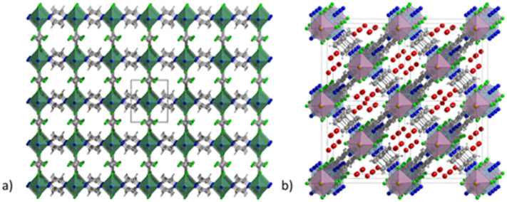
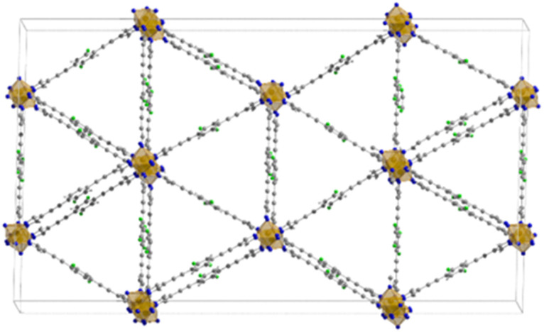
MOFs based on fluorinated anions are compounds in which the F atoms are directly bonded to an inorganic structural unit of the framework different from the organic linker. For instance, F can be present as fluoride and replace the terminal hydroxyl group in hydrated polynuclear clusters or it can coordinate single metallic or semi-metallic elements generally forming anionic moieties, such as SiF62−, TiF62−, NbOF52− and AlF5(H2O)2−. The latter approach has been extensively developed in the last decade with the pioneering work of Eddauodi and co-workers. One of the first MOFs based on fluorinated anions was reported by Adil and co-workers in 2013 where they synthetised a mixed Cu/Al metal F-MOF with the formula CuAlF4.5(OH)0.5(H2O)[HAmTAZ]2 (HAmTAZ = 3-amino-1,2,4-triazole). The structure is composed of copper-triazole square grid layers pillared by the AlF5(H2O) octahedra, generating a three-dimensional network with a pcu topology.39 In 2013 a series of super microporous F-MOFs, denoted as SIFSIX-3M were reported by the Eddaoudi group. These compounds, with the general formula MSiF6(pyrazine)2·2H2O and M = Ni, Cu and Zn, have the common feature of being based on the same structural motif, which is a square grids (sql) 2D net constituted of metals coordinated in the plane by pyrazine.12 These nets are linked to each other in the third dimension by a pillaring SiF62− to form frameworks with a primitive cubic topology. These compounds were inspired by a previously reported compound with the formula [Cu(4,4′-bipyridine)2(SiF6)]n (SIFSIX-1-Cu). The use of 4,4′-dipyridylacetylene (dpa) afforded a compound with the same topology (SIFSIX-2-Cu) but with increased pore size due the longer size of the dpa compared to 4,4′-bipyridine. The family of SIFSIX-3-M was designed from the perspective of switching the porosity towards the ultramicropore range. The use of a shorter pyrazine linker, with respect to the previous ones, shortened the metal–metal distance along the plane but maintained the same size due to the SIF62− anion, resulting in a pore of 3.84 Å (measured along the diagonal) which has dramatic implications for the pure physisorbing mechanism of CO2 at very low partial pressures. The first reported SIFSIX-3 MOF were based either on Zn, Ni or Cu and have formula M(ii)SiF6(pyrazine)2·2H2O. The structure of SIFSIX-1 is shown in Fig. 1.
Fig. 1. (a) Crystal structure of SIFSIX-1-Cu (molecular formula [Cu(4,4′-bipyridine)2(SiF6)]n), extended view along the a direction. Color code: copper olive, carbon dark grey, nitrogen blue, fluorine green, silicon light grey.12 (b) Crystal structure of NbOFFIVE-1-Ni (molecular formula [Ni(4,4′-bipyridine)2(NbOF5)]n), extended view along the a direction, the water before the activations is present in the pore. Color code: nickel light blue, niobium pink, carbon dark grey, nitrogen blue, fluorine green, water red.41.
In a recent paper DFT and Grand Canonical Monte Carlo (GCMC)-based simulations were used to model the theoretical structure and the CO2 absorption properties of several MOFs derived from SIXSIF-Ni-pyridine.
The MOFs of general formula M′FSIX-Ni-pyridine MOF series were built by changing the hexafluorinated metal ions having the same octahedral coordination M′F6 moieties (M′ = Si, Ga, Zr, Ge, Sn, Ti, V, and Nb) but keeping nickel and pyrazine as divalent cation (M = Ni) and ligand, respectively.
Then the authors modelled other structure by changing the organic linker with 4,4′-bipyridine (byp), 4,4′-azopyridine (apy), 4,4′-bipyridylacetylene (bpa), and 3,3′-di(4-pyridyl)-1,2,4,5-tetrazine (dpt).
CO2 capacity and selectivity were evaluated by theoretical gas adsorption isotherms using CO2/N2 15/85 gas streams. Notably, the working capacity of the MOFs increased with increasing the ligand size but the selectivity obviously decreased. In order to keep the same supermicropore range observed in the parent MOFs authors also constructed interpenetrated MOFs with the longer ligands and they found that interpenetration had beneficial effect in maintaining the overall absorption capacity and with high selectivity (over 2400) for the dpt-containing MOF.40 In 2016 the Eddaoudi group reported a new family of F-MOFs inspired on the same design of SIFSIX compound but they used a new fluorinated anion based on Nb, namely the NbOF52−, which displayed narrower pores respect to SIFSIX family.38 The reason is due to the longer Nb–O and Nb–F distances compared to Si–F (1.899 Å for Nb–F vs. 1.681 Å for Si–F). This resulted in larger anionic octahedra pillaring the square grid thus reducing the pore size. Authors reported the Ni-pyrazine derivative containing the NbO5F2− anion with the acronym NbOFFIVE-1-Ni and they also solved the X-ray structure containing CO2. NbOFFIVE-1-Ni at 296 K crystallised in the tetragonal space group I4/mcm with unit cell parameters a = b = 9.942(4) Å and c = 15.764(6) Å, its structure is represented in Fig. 1b. The fine tuning of the MOF pore size was found to be crucial for increasing the CO2 interaction in terms of enthalpy of absorption. This part will be discussed in the section dedicated to the application of F-MOFs. The work was further expanded in the last two years were Al and Fe dianionic clusters, namely AlF5(H2O)2− and FeF5(H2O)2− were employed for the synthesis of others isostructural MOFs AlOFFIVE-1-Ni and FeOFFIVE-1Ni. The use of tetravalent hexafluorometallate dianionic moiety as MF62−, with M = Si, Ti, Zr, Ge and Sn as fluorinated building unit was reported by Zarowotko and co-authors in 2016.41 Here a series of MOFs with the general formula [Cu6(Tripp)8](MF6)3(MF6)3·g (Tripp = 2,4,6-tris(4-pyridyl)pyridine; g = disordered guest molecules; M = Si, Ti, Ge, Zr, or Sn) were reported. The tripp linker designs cubic-octahedral cages similar to those observed in the HKUST-1 MOF but with an unusual 3,5-c topology with the anionic MF6 moieties connecting the copper centres. The result is the formation of a truncated cubic octahedron connected by the fluorinated moieties (Fig. 2).
Fig. 2. Synthesis of [Cu6(Tripp)8(MF6)3](MF6)3g and its structure.41.
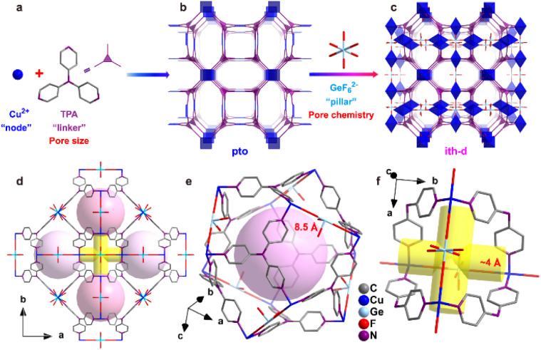
In 2023, Zhang and co-authors reported on the templating effect of GeF62− embedded in the framework of a Cu tri(pyridin-4-yl)amine (TPA) MOF, namely ZNU-6. The formula of ZNU-6 is [Cu6(GeF6)6(TPA)8]. The assembly of Cu2+ ions and TPA produced a cationic framework counter balanced by equimolar amounts of GeF6 anions with respect to copper ions resulting in a complex ith-d topological network in which icosahedral cages and 1D channels are present. Twelve 1D channels surround each cage and each interlaced channel connects four cages. The fluorinated anions are placed at the each cage edge, forming a region densely decorated with fluorine atoms. The MOF is permanently porous displaying with a BET surface area of over 1330 m2 g−1 and a micropore volume of 0.55 cm3 g−1. The schematic structure of ZNU-6 and the effect of GeF62− are depicted in Fig. 3.42
Fig. 3. Porous structure of ZNU-6. (a)–(c) Exquisite control of pore size/shape and pore chemistry in ZNU-6 from pillared (3,4)-connected pto network to GeF62− embedded ith-d topology framework; (d) overview of ZNU-6 structure with cage-like pores and interlaced channels. (e) Structure and size of the cage-like pore. (f) Structure and size of the interlaced channel connecting four cages.42.
2.2. F-MOFs based on fluorinated polynuclear secondary building units (SBU)
Other than the use of perfluorinated anions discussed in the previous section, F-MOFs can also be obtained by partial fluorination of the inorganic SBU based on polynuclear clusters and containing hydroxyl bridged μ2 or μ3 groups. Zr-based MOFs are the class of compounds most developed in the last years due to their exceptional stability.
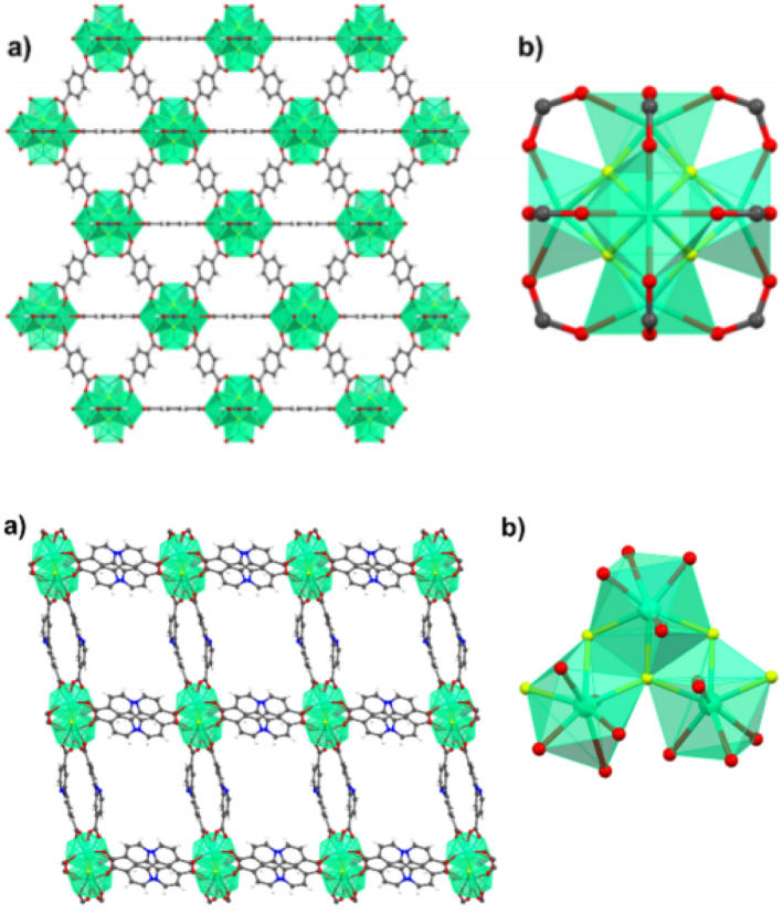
The most part of them, such as the UiO-66 and MOF-801, are based on the same hexanuclear unit with the formula Zr6O4(OH)412+. Similarly, MOFs based on trivalent or tetravalent rare earth elements have similar building units. Ce(iv) MOFs with UiO-66 structure are based on Ce6O4(OH)412+.43 On the contrary, a series of trivalent RE-MOF with fcu topology has been reported from 2013 and they are based on building units of general formula RE6(μ3-OH)8(L)12 (L = mono- or di-carboxylic linker). The use of fluorinated acid modulators such as 2-fluoro benzoic (2-fba) and 2,6 difluorobenzoic (2,6-dfba) acid with trigonal linkers also afforded new building units based on nonanuclear clusters with the formula [RE9(μ3-OH)12(μ3-O)2(L)12]. In 2021, Balkus and co-workers found an unusual mechanism in RE-MOFs where the use of 2-fba as modulator induced the substitution of fluoro-bridging groups in place of μ3-OH groups. Authors reported the 2-fba modulated syntheses of two Ho-MOFs by using benzenedicarboxylic acid (BDC) and 2,2′-bipyridine-4,4′-dicarboxylate (4,4′-BPDC).44 The MOF containing BDC has UiO-66 structure and it is based on hexanuclear Ho6 clusters bridged by the carboxylate groups in a fcu porous framework.44 The formula of these clusters is Ho6(OH)4F4(L)12 and the fluorine atoms occupy the same μ3 bridged positions generally host by OH groups. The BPDC derivative is based on trinuclear clusters forming 1D zigzag chains “ladders”. The crystal structure of Ho-UiO-66 type MOFs is reported in Fig. 4.
Fig. 4. On top: crystal structure of Ho-UiO-66 MOF. (a) Extended view along the a direction. (b) Holmium hexacluster containing μ3-F bridging groups. Reprinted with permission from ref. 44. Copyright 2021 American Chemical Society. On the bottom: crystal structure of Ho-4,4′-BPDC MOF. (a) Extended view along the a direction. (b) Holmium tricluster containing one μ3-F group. Reprinted with permission from ref. 44. Copyright 2021 American Chemical Society.
The rungs of the ladder consist of the Ho–F bonds aligned along the c-axis. These chains are connected through the carboxylate groups of BPDC, along both the a and c directions. The structure of the two MOFs and the details of the inorganic building units are shown in Fig. 3 and 4. The presence and the amount of the F atoms on the inorganic cluster was studied in detail by the authors with X-ray photoelectron spectroscopy and solid-state 19F-MAS NMR.
The mechanisms of fluorination proposed involved C–F activation and fluorine extraction mediated by Ho through two different mechanisms: single electron transfer (SET) or by fluorine transfer and benzyne formation.
Interestingly, authors claimed that similar mechanism could involve the fluorination of other MOFs when the same fluorinated modulators were used although the way to verify it is not straightforward. A theoretical DFT study was recently reported by Prasetyo and Pambudi about the effect of fluorination on the hexanuclear cluster of Zr-based MOF with MOF-801 structure (fumarate acid as linker).45 Authors found that the substitution of 1 to 4 F atoms in place of OH groups on the cluster, sensibly affects the cell dimension and the Zr–F distance were found to be longer (2.25 Å vs. 2.19 Å) for Zr–O. Authors also calculated the binding energies for H2 adsorption as function of number of F atoms substituted and they found an average increase of −5 kcal mol−1 resulting in a better affinity of the F-MOF compared to the pristine one. Similarly, the role of F atoms placed on the SBU of Mg MOF-74 was investigated in a recent theoretical paper by Nguyen and co-authors. Authors have employed ab initio molecular dynamics simulations to check the role of capping F atoms on the unsaturated metal centres of the MOF and they found that polarization of F centres on the metal sites increased the H2 affinity in term of heat of adsorption up to 3.9 kJ mol−1.46
2.3. F-MOFs based on fluorinated linkers
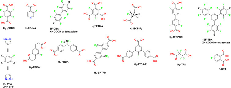
MOFs based on fluorinated linkers have been most developed respect to those based on inorganic fluorinated units thanks to the commercial availability of many fluorinated linkers and to the possibility of predicting the desired structural type in comparison with the non-fluorinated analogues. Scheme 1 reports the molecular structure of many of the linkers used in recent years, mainly based on aromatic groups containing fluorine or based on perfluorinated aliphatic chains. 4,4′-(Hexafluoroisopropylidene)bis(benzoic acid) (H2FBBA) is among the most used fluorinated linkers reported to date.
Scheme 1. Molecular structures of the fluorinated linkers discussed in this review. H2-4FBDC = tetrafluoro terephthalic acid, H2-2F-INA = 3-fluoroisonicotinic acid, 8FBDX = 2,2′,3,3′,5,5′,6,6′-octafluoro-[1,1′-biphenyl]-4,4′-dicarboxylic acid, H3-3FTMA = 2,4,6-trifluorobenzene-1,3,5-tricarboxylic acid, H2PFX = 4,4′-((2-fluoro-3,5,6-X-1,4-phenylene)bis(ethyne-2,1-diyl))bis(1H-pyrazole) where X = H, F, H2FBA = 2,2′-(2-fluoro-1,4-phenylene)diacetic acid H2FBBA = 4,4′-(hexafluoroisopropylidene), H2BPTFM = 2,2′-bis(trifluoromethyl)[1,1′-biphenyl]-4,4′-dicarboxylate), 12FTBX = 5′-(4-carboxy-2,3,5,6-tetrafluorophenyl)-2,2′′,3,3′′,5,5′′,6,6′′-octafluoro-[1,1′:3′,1′′-terphenyl]-4,4′′-dicarboxylic acid or 5,5′-(2,2′′,3,3′′,5,5′′,6,6′′-octafluoro-5′-(2,3,5,6-tetrafluoro-4-(tetrazol-5-yl)phenyl)-[1,1′:3′,1′′-terphenyl]-4,4′′-diyl)bis(tetrazole), H2-TFS = tetrafluorosuccinic acid, H2-BCP-F2 = 2,2-difluorobicyclo[1.1.1]pentane-1,3-dicarboxylic acid, H3-TTCA-F = trimethyl 2′-fluoro-[1,1′:3′,1′′-terphenyl]-4,4′′,5′-tricarboxylate, H2-TFBPDC = 3,3′,5,5′-tetrakis(fluoro)biphenyl-4,4′-dicarboxylic acid, F-OPA = F-substituted o-phthalic acid.
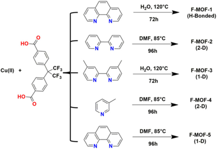
The use of H2FBBA was first reported in 2011 by Banerjee and co-workers by using Cu(ii) and several nitrogenated chelating co-ligands as reported in Scheme 2.47
Scheme 2. Reaction conditions for the syntheses of F-MOF-x from the work of Banerjee and co-workers.47.
The syntheses afforded five F-MOFs with various structures and different dimensionality. DMF or water were used as solvent and the temperature of reaction ranged from 358 to 393 K. H2FBBA was also used in 2018 by Morsali et al. with Zn and two nitrogenated pyridine-based co-linkers, namely 4-bpdb = 1,4-bis(4-pyridyl)-2,3-diaza-1,3-butadiene and 4-bpdh = 2,5-bis(4-pyridyl)-3,4-diaza-2,4-hexadiene for the synthesis of two isostructural MOFs with the formula [Zn2(HFBBA)2(4-bpdh)]·0.5DMF and [Zn2(HFBBA)2(4-bpdb)]·2DMF respectively (TMA and HTMA from the original paper).38
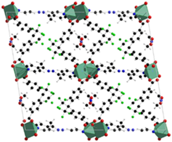
The structures are composed of paddlewheel Zn2(COO)4 connected by the monoprotonated HFBBA ligand to form square grids connected in the third dimension by the pillaring 4-bpdh or 4-bpdb linkers. Topological analysis revealed a rare point symbol (44·610·8) observed only in a limited number of compounds all based on the coexistence of bent and linear ligands. The structure of [Zn2(HFBBA)2(4-bpdh)]·0.5DMF is shown in Fig. 5.
Fig. 5. Structure of the [Zn2(HFBBA)2(4-bpdh)]·0.5DMF, extended view along the 120 hkl direction. Color code: zinc light blue, carbon grey, nitrogen blue, fluorine green, oxygen red.48.
The perfluorinated moieties of the H2FBBA linker faced each other along the squared channels by designing a region rich in fluorine atoms which rendered these compounds highly hydrophobic and useful for heterogeneous catalysis in aqueous environment, namely for Knoevenagel condensation reaction.
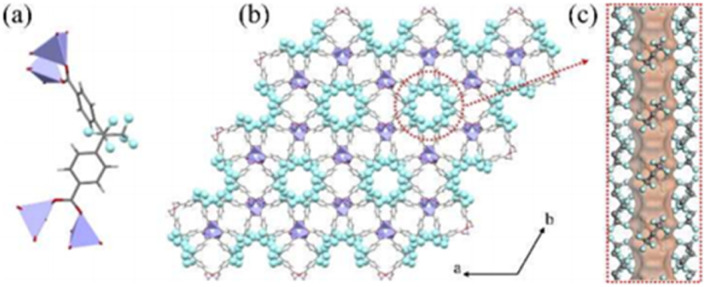
Very recently, rational design of H2FBBA and Zn allowed the obtainment of an ultramicroporous FMOF with perfluorinated 1D channels with the formula ZnFBBA. The structure was already reported by Monge et al. in 2005. The structure is composed of infinite chains of corner-sharing ZnO4 tetrahedra which form a typical paddle-wheel secondary building units. These SBUs are connected through FBBA linkers designing two parallel one-dimensional (1D) channels in which the perfluorinated methyl groups are placed in a helical conformation along the c-axis. These channels are therefore strongly decorated by fluorine atoms resulting in a small average size of 5.2 Å. The structure of ZnFBBA and the details of the 1D ultramicroporous channels are shown in Fig. 6.48
Fig. 6. (a) The coordination environment of ZnO4 and FBA2 linkers. (b) Orthographic views down the c axis of Zn-FBA. (c) The hexagonal pore structure in Zn-FBA along the c axis illustrated by the Connolly surface in orange (zinc = lavender; oxygen = red; carbon = gray; fluorine = light blue; hydrogen = white). Reproduced from ref. 48 with permission from John Wiley & Sons, copyright 2022.
This compound displays an unusual sorption behavior towards C2 hydrocarbons, exhibiting a reverse order of selectivity among acetylene, ethylene and ethane, as further discussed in the paragraph dedicated to applications.
Lastly, H2FBBA was also employed in 2019 to build a F-MOF based on Cu paddlewheel SBU with general formula [Cu2(FBBA)2(H2FBBA)].
The MOF featured ordered 1D channels designed by Cu2 paddlewheel linked each other by a (FBBA) deprotonated and one protonated (H2FBBA) linker.
The bent carboxylic linkers expanded the framework in the third dimension thus designing a pillared 3D network based on the connection of a 2D square grid trough the H2FBBA linker. In this MOF authors evidenced a bimodal distribution of small cavities of size 9.4 × 9.2 Å2 and 5.6 × 4.2 Å2 respectively and a third hidden one 8.8 × 4.7 Å2 connected to the two tubular cavities by a 1D narrow channel consisting of fluorinated windows with a 2.5 Å wide opening.
Depending on the temperature, these two apertures show a gate-opening effect and the cavities get successively accessible for hydrogen with increasing temperature. The MOF was also employed for the separation of deuterium from H2/D2 mixtures.49 A similar linker to H2FBBA, namely 2,2′-bis(trifluoromethyl)[1,1′-biphenyl]-4,4′-dicarboxylate hereafter H2BPTFM, was recently employed by Chen et al. for the construction of a copper(ii) based MOF with the formula [Cu3(BPTFM)2 guest].50
The compound, named by the authors as LIFM-100 in the original paper, is a 3D coordination polymer which displays a narrow-pore large-pore phase transition when evacuated from the solvent guest molecules. The structure of LIFM-100 np and lp phases is shown in Fig. 7.51
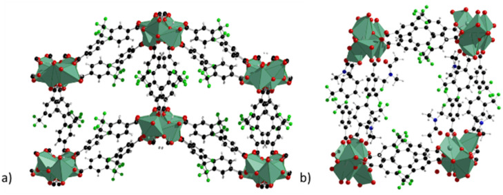
Fig. 7. Crystal structure of LIFM-100 phases with narrow pore (a) and with large pore (b), extended view along the a direction. Colour code: copper olive green, carbon grey, nitrogen blue, fluorine green, oxygen red.51.
The structure is composed of 1D chains constituted of Cu–O SBU with three different coordination environments and two types of carboxylate groups. All the ligands and Cu–O chains formed one type of double-walled tetragonal channel with 9 Å diameter and a surface decorated with F atoms, similarly to that observed with the trifluoromethyl groups of the H2FBBA linker. This generates ahydrophobic region within the channel. The lp and the np phases can be interchanged by crystal-to-crystal phase transformation if the lp phase is previously evacuated and then soaked in different organic solvents. The flipping of one of the free oxygen atoms of a non-coordinated carboxylic group determines the transformation driven by a change in the coordination environment of one copper atom, which becomes five-coordinated in square pyramidal mode.
The presence of small channels decorated by –CF3 groups is analogue to that observed for F-MOFs based on H2FBBA, as described above, and the two MOFs display interesting properties in separation of R22 gas from gas mixtures.
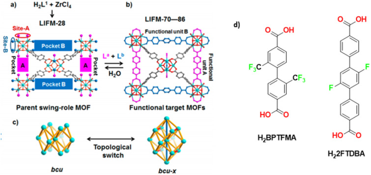
In a 2017 paper the same group prepared a family of multivariate MOFs starting from the LIFM-28 precursor. One of the reported MOFs, LIFM-86, was functionalized on both the pockets with two fluorinated linkers, 2,2′-bis(trifluoromethyl)-4,4′-biphenyldicarboxylate, namely H2BPTFMA and the 22,25-difluoro[11,21:24,31-terphenyl]dicarboxylic acid as shown in Fig. 8. H2BPTFMA was also employed by Su and co-workers in 2017 for achieving fluorinated functionality on a preformed Zr-based MOF, namely LIFM-28 via a post-synthetic variable spacer installation (PVSI) strategy. LIFM-28 contains an 8-connected Zr6 clusters with four pairs of terminal water molecules, thus designing two different insertion sites (A and B). Site A is suitable for the insertion of short linker, based on biphenyldicarboxylate and its analogues whereas site B is suitable for the insertion of longer spacers based on the terphenyldicarboxylate and its analogues, as depicted in Fig. 8.52
Fig. 8. (a) Synthesis of the parent LIFM-28 for multirole MOFs showing replaceable coordination sites and pockets. (b) Transformation to functional MOFs LIFM-70–86 via spacer installation. (c) Framework topology interconversion. (d) Linkers 2′-bis(trifluoromethyl)-4,4′-biphenyldicarboxylate (H2BPTFMA) and the 22,25-difluoro[11,21:24,31-terphenyl]dicarboxylic acid (H22FTDBA). Adapted with permission from ref. 52. Copyright 2016 American Chemical Society.
F-MOFs based on aromatic fluorinated linkers have been widely developed in the last few years by using fluorinated analogues of simple linkers normally used in MOF synthesis such as terephthalic (H2BDC) acid or trimesic acid (H3BTC).49 One of the first attempts of fluorination of a known MOF was proposed in 2013 by Van deer Vort et al. used 2F-H2BDC linker to afford a V(iii) and an Al(iii) F-MOF of formulas [M(iii)(OH)(BDC-F)]n(solvent).53
The MOFs were based on [M(iii)O4(OH)2] octahedra interconnected by fluoro-terephthalate linkers to form one-dimensional rhombic-shaped channels able to change their size when subjected to solvent removal or thermal stimuli thus changing from a narrow pore to large pore phases. Respect to the non-fluorinated analogues the compounds showed an increased thermal stability and a better affinity towards CO2 lowering the pressure of np to lp phase transition. The H2O sorption experiments were also carried out showing that the fluorination imparted noticeable hydrophobicity to both of the partially fluorinated compounds. F-H2BDC and 2,5 (2F)-H2BDC have also been employed in a very recent paper by Zhang and co-authors for the preparation of fluorinated UiO-66 and used for iodine absorption from wet iodine vapours.55
A series of fluorine substituted ortho-phthalic acids (H2OPA), namely 3-F-OPA, 3,6-(F)2-OPA and the fully tetrafluoro substituted linker (-F)4-OPA were employed in 2023 by Hu and co-workers for the synthesis of four isoreticular MOFs based on Ni and 2,4,6-tri(4-pyridinyl)-1,3,5-triazine (TPT) with the general formula [Ni(TPT)(R-OPA)(H2O)]·x(solvent). The MOFs named as TKL104-107 are based on Ni octahedra 1D chains coordinated by three different TPT linkers, two fully deprotonated R-OPA2− linkers and one apical water molecule, designing a honeycomb-like structure with trigonal channels running along the c-axis. The channels have an opening size of up to 6 Å, which are decorated by F-atoms belonging to the linkers. The compounds exhibited different stability depending on the positions of the F atoms. In particular, TKL 104, the MOF with fluorine in meta positions, was less stable upon activation than to the other MOFs with fluorine in ortho position and the one containing the fully fluorinated linker. The four MOFs were employed for the separation of ethane/ethylene as discussed in the section devoted to applications.56
Tetrafluoro terephthalic acid (H24FBDC) was employed in 2017 by our group for the synthesis of two Ce-MOFs with MIL140A and UiO-66 structure respectively.29 The two compounds could be obtained in water by slightly changing the synthetic conditions. Ce-F4MIL140A is the most interesting compound, for its peculiar CO2 absorption properties. Its polyhedral representation is depicted in Fig. 9.
Fig. 9. Crystal structure of Ce-MIL140A, view along the c axis. Color code: cerium cluster orange, carbon grey, fluorine green.29.
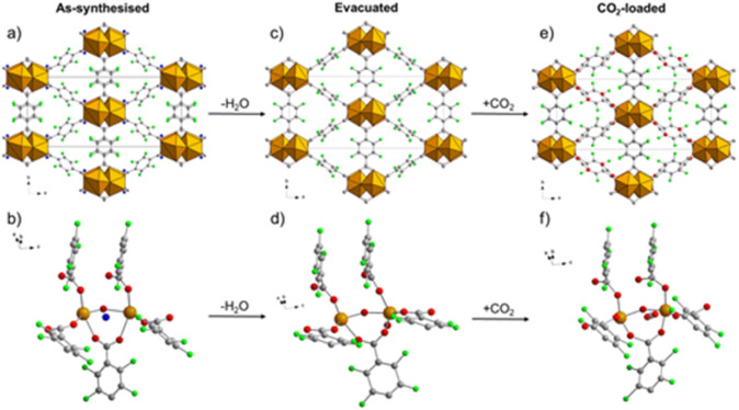
The structure of Ce-F4MIL140A is constituted by the connection of one-dimensional inorganic chains, composed of Ce(iv) ions with coordination 8, carboxylate groups belonging to the linker bridging two different Ce atoms and μ3-O species, via the perfluorinated aromatic rings of the linker. This structure possesses narrow triangular channel-like pores lined with the fluorine atoms belonging to the linker. A water molecule coordinated to the Ce(iv) ions making H-bonding interaction with neighbouring oxygen atoms. When removed by thermal treatment, an unsaturated coordination site is created that it is crucial for the coordination of the adsorbed carbon dioxide molecules, inducing a strong affinity for this molecule. Notably, if the synthetic conditions are changed, the fluorinated F4UiO-66 phase is formed. Kinetics of crystallization of the two phases and the best conditions for getting pure and well crystallized compounds were studied using in situ synchrotron radiation light in 2021.57 A recent study made use of several coupled techniques to fully understand the dynamic of CO2 adsorption in term of structural changes of the MOF and of heat of adsorption. The position of adsorbed CO2 molecule was determined at atomic scale by using synchrotron radiation high resolution powder diffraction and EXAFS. The proposed mechanism (Fig. 10) involved a concerted ring rotation and the presence of unsaturated metal site interacting with CO2 oxygen atoms.58
Fig. 10. Comparison of the crystal structure viewed along the c axis and the local environment around the adsorption site of the as-synthesised (a and b, respectively), evacuated (c and d, respectively) and CO2-loaded (e and f, respectively) forms of Ce-F4MIL140A. Colour code: Ce, orange; F, green; C, grey; O, red; H2O, blue. H atoms not shown because their positions cannot be determined from PXRD data. Reproduced from ref. 58 with permission from the Royal Society of Chemistry, copyright 2023.
In 2022, Wang and co-authors reported the synthesis of a hierarchically porous Al-MIL-53 containing H2-F4BDC using a monocarboxylic acid as modulator. The use of the modulator led to the formation of instable Al complexes replaced by the F4BDC groups thus forming the fluorinated MOF.59 The direct synthesis of the perfluorinated MIL-53 MOF based on H2-F4BDC was carried out by our group via a solvent-free synthetic route. F4-MIL-53(Al) has formula Al(OH)(F4BDC)·0.4H2O and it is constituted of infinite 1D inorganic chains made of Al octahedra linked each other by the perfluorinated linker thus designing rhombic channels of about 10.5 × 9 Å size and possessing a BET surface area higher than 1000 m2 g−1. Interestingly, this material exhibits a reversible phase transition np to lp purely induced by temperature in a very narrow temperature range (between 220 and 225 °C).60
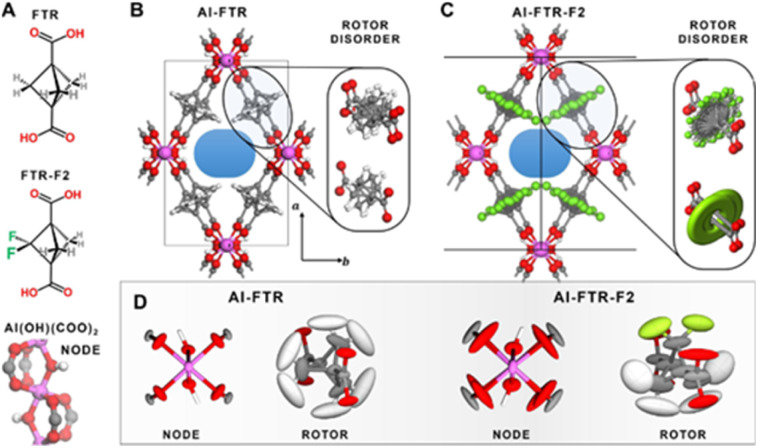
Two MOFs based on [Zr6O4(OH)4]12+ clusters, using for the first time a fluorinated alkyl linker, were recently reported by Morelli and co-workers. The MOFs are based on tetrafluoro succinate (TFS) as linker which also afforded another MOF with MOF-801 structure type (PF-MOF-2) in which both fumarate and TFS are included in the framework thanks to post synthetic modification (PSM). NMR analysis on the digested samples coupled with TGA and gas sorption indicated the amount of fluorinated linkers incorporated in the framework. Very likely, the fluorinated moieties were placed on the defective sites (missing clusters) of the MOFs.30 Very recently the molecular rotor H2-BCP-F2 and its non-fluorinated analogue were employed by Comotti and co-workers to build up two Al-MOF (Al-FTR and Al-FTR2) with MIL-53 like structure.61
The structure is constituted of infinite 1D corner-sharing AlO4(OH)2 octahedra linked each other by the carboxylate groups of BCP-based ligands, which are arranged perpendicular to the propagation direction of the columns, thus designing regular rhombic shaped channels. Variable temperature synchrotron diffraction down to 4 K was used in order to mode the rotor disorder along the rotation axis and the distance shift between the rotors in both fluorinated and non-fluorinated cases. Laser-assisted hyperpolarized 129Xe NMR coupled with PW-DFT calculations were also employed in order to probe the free space and the molecular interactions with the linker by changing the temperature. Calorimetric measurement evidenced a high Qst of interaction to CO2 of the F-MOF (30 kJ mol−1) at 195 K, confirming the beneficial effect of F towards CO2. The structures and the rotor disorder of the two MOFs are shown in Fig. 11.61
Fig. 11. Chemical structure of the ligands (A). Polyhedral representation of the two MOFs (B and C) and rotor disorder drawn as ellipsoid of nodes and linkers (D). The thermal ellipsoids for the Al(OH)(COO)2 nodes as well as the FTR and FTR-F2 rotors in both MOFs are reported, as derived from PW-DFT phonon calculations. The ellipsoids are displayed with a 95% probability factor. Atom labeling: hydrogen = white, carbon = grey, oxygen = red, fluorine = green, aluminum = purple. Reproduced from ref. 61 with permission from John Wiley & Sons, copyright 2022.
Concerning the use of longer linkers, it is worth to mention the 2013 paper by Popov and co-authors reporting the Cu-catalyzed-cross-coupling reaction between 2,3,5,6-tetrafluorobenzonitrile and 4-iodo-2,3,5,6-tetrafluoro benzonitrile to afford a octafluoro-biphenyl cyano precursors.
The structure was then converted to 8F-BDCA (see Scheme 1) or in the bis-tetrazole analogue (8F-BTAZ) respectively, via acid hydrolysis or through azide reaction catalyzed by ZnCl.50
The two linkers were then employed for the synthesis of three MOF based on Cu and containing the two linkers. MOFF-1, as named by the authors, with the formula Cu(8F-BDCA)(MeOH) is two paddle-wheel secondary building units linked each other by the perfluorinated linker designing a square grid lattice.
Adding another co-linker, namely 1,4-diazabicyclo[2.2.2]octane (DABCO) a new MOF (MOFF-2) with the formula Cu2(8F-BDCA)2(DABCO) is obtained. In this case the nitrogen is coordinated by the Cu atoms of the SBU thus resulting in a 3D pillared network. The use of the latter 8F-BTAZ linker afforded another MOF with the formula Cu(8F-BTAZ)(H2O), namely MOFF-3. The network is constituted of infinite CuO2N4 units in which the copper atoms are octahedrally coordinated by a bridging water molecule and the tetrazole linkers resulting in 3D MOF with rhombic 1D infinite channels running along the c-axis. The presence of highly stacked perfluorinated linkers render these MOF extremely hydrophobic, as verified by contact angle measurements. The same group expanded this approach in 2015 by using 1,3,5-tris(2′,3′,5′,6′-tetrafluoro-4′-cyanophenyl)benzene (12F-BTCN) as building block to afford the tris-carboxylic (12F-BTCOOH) and the tris-tetrazolate linkers (12F-BTCTZA), used with Cu(ii) to form two highly porous zeotype MOFs with the same structure.60 The structure of the two MOFs with the formula Cu2(12F-BTCOO)2(H2O)3
(MOFF-4) and [Cu(H2O)6]1.5[(Cu4Cl)3(12F-BTTZA)8(H2O)12] (MOFF-5) is shown in Fig. 12. The two MOFs have the same topology such as that of HKUST-1 and they are constituted of paddlewheel Cu2(COO)4 clusters in the case of MOFF-4 and by square planar [Cu4Cl]7+ clusters bridged by eight tetrazolates in the case of MOFF-5.
Fig. 12. Crystal structure of (a) MOFF-2 (b) MOFF-4. Colour code: copper olive green, carbon grey, nitrogen blue, fluorine green, oxygen red.
Each cylindrical cage is formed from six [Ni3(μ3-O)] units, six carboxylate ligands and two ligands. Each trigonal bipyramidal cage is built from five [Ni3(μ3-O)] units, six dicarboxylate ligands and three ligands.62
The two MOFs have specific surface area as high as 2500 m2 g−1 and they were used for the separation of light fluorocarbon gases.
In 2022 Chen and co-authors reported on the structure and gas separation properties of a mixed linker F-MOF based on Ni, 3,3′,5,5-tetrakis(fluoro)biphenyl-4,4-dicarboxylic acid (H2-FBPTDC) and 2,4,6-tri(4-pyridinyl)-1,3,5-triazine (tpt) (JXNU-12(F)).63
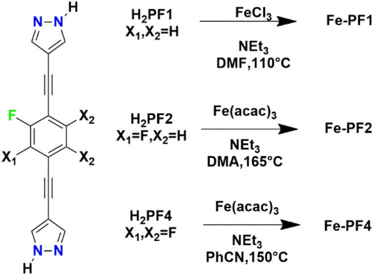
The structure is composed of an anionic [Ni3(μ3-O)(TFBPDC)3(tpt)]2− framework counterbalanced by (CH3)2NH2+ ions derived from the decomposition of DMF solvents. The framework could be depicted as a variant of MIL-88 structure but the presence of linker acted as pore partitioning agent. The use of the pore partition agent of resulting in the formation of cylindrical cages and trigonal bipyramidal cages. Each cylindrical cage is formed from six [Ni3(μ3-O)] units, six dicarboxylate ligands and two ligands. Very recently Comotti and co-authors reported on a family of isostructural MOFs based on Fe(iii) and bis-pyrazolate linkers with different fluorination degree.49 The linker H2PFX (with X = H or F) is depicted in Scheme 3.
Scheme 3. Synthetic conditions for the preparation of the three fluorinated bis(pyrazolyl)-based MOFs.49.
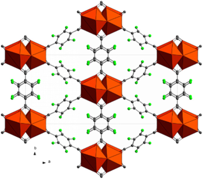
The three MOFs Fe-PF1, 2 and 3, containing the mono-, bis- and tetra-fluoro linkers respectively are isostructural and constituted by the same 1D building unit in which Fe3+ is six-coordinated with an octahedral environment by the nitrogen atoms belonging to the PFX pyrazolate moieties. The structures display triangular 1-D channels where the faces are defined by the ligands and the metal nodes occupy the edges. The structure of Fe-PF4 is shown in Fig. 13. Pore size distribution from N2 adsorption isotherms revealed a 8 Å average size in good agreement with the DFT calculations. Authors have used several experimental techniques (such as calorimetry and CP-MAS 1H, 13C and 19F solid state NMR) to elucidate the behaviour of the fluorinated rotors and the influence on CO2 adsorption properties. While in the case of mono- and bis-fluorinated linker the central benzene rings are placed in parallel way along the channel direction they are held in this position by a number of F–H H-bonds among the partially fluorinated linkers.68 On the contrary, in tetrafluorinated analogue (Fe-PF4), the absence of the H-atoms on the ring does not permit H-bond interactions and the rings resulted tilted each other of about 30° respect the channel axis. The linker (2E,20E)-3,3′-(2-fluoro-1,4-phenylene)diacrylic acid (H2FBDA, see Scheme 1) was employed in 2019 by Zhao and co-workers for the synthesis of fluorinated analogues of UiO-66 Zr-MOF.64
Fig. 13. Crystal structure of Fe-PF4 MOF extended view along (1 1 1) hkl direction. Colour code: iron polyhedra orange, carbon grey, nitrogen blue, fluorine green and hydrogen white.68.
The MOF, namely ZJU-800, is based on hexanuclear [Zr6(O)4(OH)4]12+ clusters coordinated by the carboxylates of FBDA2 ligands to form a three-dimensional fcu structure. Fluorine atoms belonging to the central phenylene ring are exposed into the tetrahedral and octahedral pores and they confer to the MOF an increased affinity towards methane, resulting in 10 mmol g−1 of CH4 adsorbed at 50 bar.65 Finally, 3-fluoro-isonicotinic acid (HFINA, see Scheme 1) was used in 2021 by Li and co-authors for the syntheses of two F-MOF based on Cu, namely Cu-FINA1 and Cu-FINA2, which possess a bcu and 3,5-connected topologies respectively. They are both based on small size square channels (7.86 × 6.95 Å and 5.48 × 4.87 Å window size for Cu-FINA1 and Cu-FINA2 respectively) with the F-atoms exposed in the inner part of the channels.66
3. Application of F-MOFs
3.1. CO2 absorption and selectivity
Some of the F-MOFs here discussed have found to possess a superior affinity towards CO2 and they may effectively be employed as physisorbents for targeted application such as absorption of CO2 directly from air (DAC, 400 ppm concentration), from confined spaces (1–5% wt concentration) and from industrial steel, cement and thermoelectric plants point sources (CCS, 7–15% wt concentration).54 Common chemisorbents for low concentration CO2 environment, such as aqueous alkylamine or concentrated hydroxides solutions display a high heat of absorption (Qst) in the 80–102 kJ mol−1 range thus offering the best uptake at these conditions but with a high energy penalty due to the sorbent regeneration.
F-MOF used as physisorbents are expected to work at lower Qst comprised in the 40–60 kJ mol−1 range but with the advantage of being easily regenerated trough pressure swing or vacuum swing absorption.30 In addition, the presence of fluorine renders these MOF hydrolytically stable and less prone to be degraded by water vapor and moisture.
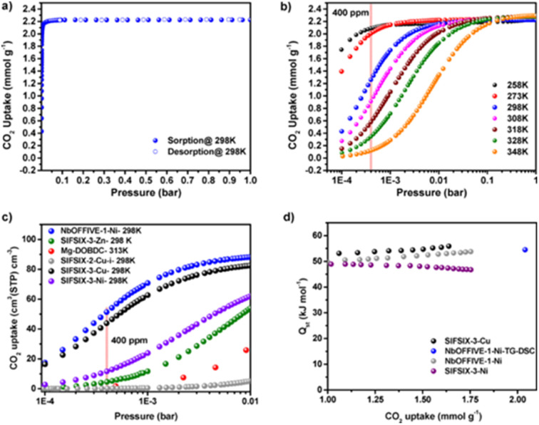
F-MOF based on fluorinated anions reported by Eddaoudi were employed for DAC applications. In particular, SIFSIX35 and NbOFFIVE31,54 MOFs have a fine-tuned affinity towards CO2 measured in terms of Qst and depending on the F⋯F distances within the square channels and on the polarity of the F atoms when linked to a more electropositive elements such as Nb (NbOFFIVE-Ni) in place of Si (SIFSIX-3-Cu). For that concerns SIFSIX, the comparison of SIFSIX-3-Zn (Qst = 45 kJ mol−1, F⋯F distance = 6.784(1) Å), SIFSIX-3-Ni (Qst = 47 kJ mol−1, F⋯F distance = 6.694(1) Å), and SIFSIX-3-Cu (Qst = 54 kJ mol−1, F⋯F distance = 6.483(1) Å) revealed a stronger interaction of CO2 when the size of the square-shaped channel is further contracted. The substitution of SiF62− with NbOF52− lead to a better environment for CO2 molecules inside the pores, as the results of longer Nb–F bond compared to Si–F which further reduces the F⋯F distances to 3.210(8) Å as compared to the 3.694(1) Å of SIFSIX-3-Ni. Single crystal studies of the CO2@NbOFFIVE-Ni revealed strong interactions between the negatively charged F-atoms and the electrophilic C atom of CO2. In terms of sorption properties, NbOFFIVE-Ni has the highest loading capacity at 400 ppm compared to similar materials as depicted in Fig. 14.54
Fig. 14. (a) CO2 adsorption isotherm for NbOFFIVE-1-Ni up to 1 bar and 298 K. (b) CO2 adsorption isotherms for NbOFFIVE-1-Ni at different temperatures. (c) Comparison of the CO2 uptake at low pressures between NbOFFIVE-1-Ni and the SIFSIX family as well as the Mg-MOF-74, one of the best MOF for low-pressure CO2 adsorption. (d) CO2 heat of adsorption for NbOFFIVE-1-Ni as compared to that of SIFSIX-3-Ni and SIFSIX-3-Cu, determined using multiple CO2 adsorption isotherms as well as TG-DSC measurements. Reprinted with permission from ref. 54. Copyright 2016 American Chemical Society.
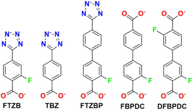
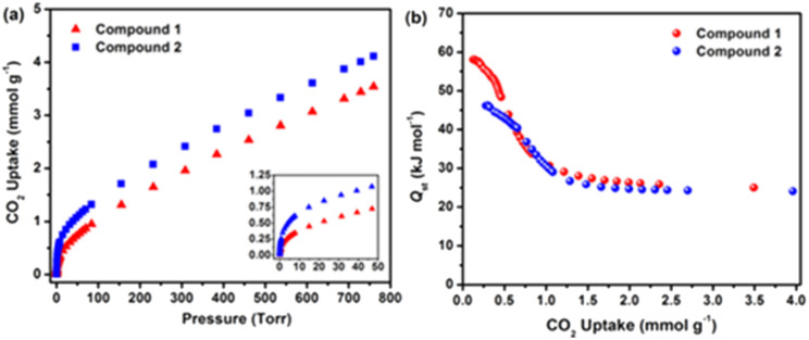
RE-MOFs containing the fluorinated linkers, as those shown in Scheme 4, reported by Eddaoudi in 2013, were also tested for CO2 absorption. In particular, compounds built with linker 2-fluoro-4-(1H-tetrazol-5-yl)benzoic acid (H2FTZB) with the formula [(CH3)2NH2]2[Tb6(μ3-OH)8(FTZB)6(H2O)6]·(H2O)22 (1) and the Y analogue [(CH3)2NH2]2[Y6(μ3-OH)8(FTZB)6(H2O)6]·(H2O)52 (2) show a remarkable CO2 absorption at 1 bar and 293 K up to 4.1 mmol g−1 being among the best performing materials in the field (Fig. 15).67
Scheme 4. Representation of the organic linkers present in RE-MOFs. H2FTZB = 2-fluoro-4-(1H-tetrazol-5-yl)benzoic acid, H2TZB = 4-(1H-tetrazol-5-yl)benzoicacid, H2FTZBP = 3-fluoro-4′-(2H-tetrazol-5-yl)biphenyl-4-carboxylic acid, H2FBPDC = 3-fluorobiphenyl-4,4′-dicarboxylic acid, H2DFBPDC = 4′-cyano-3-fluorobiphenyl-4-carboxylic acid and 3,3′-difluorobiphenyl-4,4′-dicarboxylic acid.67.
Fig. 15. (a) CO2 data for 1 and 2 at 298 K. The inset shows the steeps lope for 1 and 2 up to 50 Torr. (b) Qst in 1 and 2 calculated from the 258, 273, and 298 K adsorption isotherms. Reprinted with permission from ref. 67. Copyright 2013 American Chemical Society.
NbOFFIVE-Ni, named by the authors as KAUST-7 MOF, and an its isostructural Al based analogue KAUST-8, ([Ni(AlF5(OH2))(pyrazine)2]2H2O), were also employed for SO2 trace removal from flue gas and air.28,40 Also, as in the case of CO2, SO2 molecules could fit into the square channels and they were strongly stabilized by a number of weak interactions among the F-atoms of the pillar and the electro-positive sulphur atoms and by a net of weak H-bonds between oxygen atoms and the C–H group of the pyrazine moieties. Isosteric heat of adsorption resulted as high as those observed for CO2 (about 65 kJ mol−1 for KAUST-7). Both MOFs were studied for their adsorption and separation properties with cyclic column breakthrough tests using different gaseous mixtures resulting in a good uptake (≈2.2 mmol g−1) of SO2 in a SO2/N2: 7/93 mixture. With a SO2/CO2/N2: 4/4/92 gas mixture a simultaneous and equal retention time in the column for SO2 and CO2 was observed, displaying an identical uptake of ≈1.1 mmol g−1, consistent with the simulated energetic trends for both the polar molecules. Similar results were also observed for KAUST-8 MOF.
The two MOFs were also tested at lower SO2 and CO2 was observed, displaying an identical uptake of ≈1.1 mmol g−1, consistent with the simulated energetic trends for both the polar molecules. Similar results were also observed for KAUST-8 MOF. The two MOFs were also tested at lower SO2 concentration of 250 to 500 ppm in different gas mixture steams resulting in a very similar selectivity towards CO2 and SO2 (SO2/CO2 selectivity ≈1). More recently, AlFFIVE-1-Ni (KAUST-8) and its Fe(iii) analogue FeFFIVE-1-Ni, were also employed by the same research group for the complete dehydration from gas steams containing CO2, N2, CH4, and heavier hydrocarbons typical of natural gas.39 Dehydration mechanism was studied by several coupled experimental and theoretical techniques.
The high dehydration properties towards humid steam gases were enhanced by the high stability of the two compounds. The H2O Qst values for both AlFFIVE-1-Ni and FeFFIVE-1-Ni were evaluated by DSC and resulted in 63 kJ mol−1 and 64.7 kJ mol−1, respectively.
Both materials could be mildly re-activated at relatively low temperatures (378 K) if compared with traditional salt-based absorbents. Among the F-MOFs based on fluorinated linker Ce-F4MIL140A shows an outstanding IAST (about 1900) selectivity towards CO2 in a 0.15 : 0.85 CO2 : N2 mixture at 293 K and 1. The isotherm is S-shaped, typical of so called “phase change” materials and the pores undergo CO2 saturation over a small pressure range.29
This high affinity towards CO2 could be explicated trough a concerted mechanism of CO2 coordination on an unsaturated site on the Ce coordination sphere generated upon activation and favorable F–C interactions of central CO2 carbon atom with the fluorinated rings. Finally, Fe-PFx MOFs discussed in the previous section have a considerable affinity towards CO2 in terms of overall loading, under the mild conditions of 298 K and 1 bar. In particular, Fe-PF2 MOF reached 3.2 mol g−1, whereas the enthalpies of adsorption, measured through microcalorimetry ranged from 28 up to 33 kJ mol−1 for the fully fluorinated Fe-PF4 MOF.68 PF-MOF with MOF-801, reported by Morelli Venturi in 2022 showed a certain selectivity for CO2 thanks to the presence of the fluorinated chains. Rising trends in the Qst and in calculated IAST selectivity (MOF-801 < PFMOF-2 < ZrTFS), proportional to the quantity of the fluorine incorporated in the framework, occurred. Despite an ideal IAST selectivity (100%) ZrTFS presents a lowering in the total amount of CO2 captured (2.5% wt at 298 K and 5.4% wt at 273 K) due to a window size limitation in the diffusion through the MOF pores of gas molecules. Instead, PFMOF-2 is a good compromise between selectivity (41%) and CO2 captured (9.3% wt at 298 K and 12.2% wt at 273 K).30
3.2. Separation of light hydrocarbons and fluorocarbons
In the last few years, F-MOFs were found to be highly efficient also for the separation of gaseous light hydrocarbons both among them or from streams containing other molecules like CO2/H2/N2 and water.
This section deals mainly with the application of some selected F-MOFs for the separation of light hydrocarbons, particularly those with few carbon atoms (C2/C3). A brief overview on the separation of fluorocarbons gases is also included. Separation of light hydrocarbons is a challenging issue in industry owing to their similar physical properties, which make the conventional separation techniques very difficult. In this regards MOFs represent valuable materials to be employed and developed. Among light hydrocarbons C2H2 is an important gas used as a fuel in welding and widely used as reagent in various industrial processes to form plastics, acrylic acid derivatives, etc.69 On the other hand also propylene is used for the synthesis of several value-added products as polypropylene, acrylonitrile and propylene oxide.70,71 A very important separation is that between propyne/propylene (C3H4/C3H6) which is considered one of the most challenging and desired processes.72 Pillaring fluorinated MOFs of the SIFSIX family previously described are well performing materials for such kind of application. For instance, SIFSIX-3-Ni and SIFSIX-2-Cu were found to have high selectivity towards propylene in the C3H4/C3H6 separation but low loading stability in humid condition. This was partially due to the low stability of SiF62− anion. In 2016 Zaworotko reported the first example of TiF62− hybrid cage-like MOF Tripp-Cu-TIFSIX, (Tripp = 2,4,6-tris(4-pyridyl)pyridine), making use of TiF62−.44 However also this compound was found to be not stable upon activation, probably for the formation of pentacoordinated Cu moieties. A very recent paper from Zhang and co-authors reported the synthesis of a very stable MOF, namely ZNU-2 based on TiF62− anion Cu2+ and tri(pyridin-4yl)amine (Tripa).73 The MOF based on the tritopic Tripa linker connected the copper atoms to form complex icosahedral cages pillared by the TiF62−. This compound displayed high loading capacity for C3H6 and C3H4 at 298 K and 1 bar of 7.7 and 5.3 mmol g−1 respectively. C3H4/C3H6 selectivity on ZNU-2 at 298 K was calculated by using ideal adsorbed solution theory (IAST) and for a 1/99 physical ideal mixture it was found to be 12.5. Increasing the ratio of C3H4 in the gas mixture leads to improved C3H4/C3H6 selectivity, at 13.7 and 16.2 for 10/90 and 50/50 C3H4/C3H6 mixtures, respectively. Qst values at near-zero loading for C3H4 and C3H6 were 43.0 and 34.5 kJ mol−1. These values are slightly lower than other MOFs for similar applications but allow facile recovery of C3H4 by desorption under mild conditions. Another important field of application concerns the C2 hydrocarbons separation, namely acetylene (C2H2)/ethylene (C2H4)/ethane (C2H6). In literature there are several examples of MOFs used for such kind of separation.74 They are based on pores of small size decorated with polar groups. They normally displayed a C2H2 > C2H4 > C2H6 selectivity order, thus preferring fully unsaturated molecules. The MOF ZnBFA reported in 2022 by Zhao and co-workers and discussed in the previous section was employed for C2 hydrocarbon separation and the fully fluorinated 1D channels, constructed from the H2BFA linker, strongly interacted with the C2 molecule but with a reverse order respect that normally observed.47
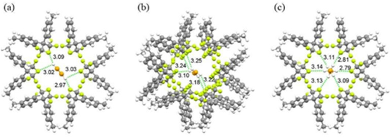
The adsorption amounts of C2 hydrocarbons were reported by the authors and they were found to be 1.35 mmol g−1 and 1.25 mmol g−1 at 273 K and 298 K under atmospheric pressure for C2H6, respectively, 1.27 mmol g−1 and 1.14 mmol g−1 for C2H4 and 1.17 mmol g−1 and 1.03 mmol g−1 for C2H2 under the same conditions.48 In terms of Qst, ZnBFA exhibited a high enthalpy of adsorption for C2H6 of 42.8 kJ mol−1, a value higher than that measured for C2H4 (39.8 kJ mol−1) and C2H2 (29.7 kJ mol−1). DFT calculations were carried out in order to understand the higher C2H6 selectivity and it was justified by the presence of a stable H–F bonds net between the methylene groups and the fluorine atoms of the MOF channel, as depicted in Fig. 16.48
Fig. 16. DFT-D calculated (a) C2H2, (b) C2H4, and (c) C2H6 adsorption locations in Zn-FBA. The unit for bond length is Å, carbon, fluorine, and hydrogen atoms in the framework represented by grey, green, and white, respectively, carbon and hydrogen atoms in adsorbate represented by orange and white, respectively, carbon and hydrogen atoms in adsorbate represented by orange and white, respectively. Reproduced from ref. 48 with permission from John Wiley & Sons, copyright 2022.
The fluorine-substituted o-phthalic acid-based MOFs (TKL 105–107) reported by Yu and co-authors in 2023 showed good selectivity for C2H6 over C2H4 and were employed for such kind of separation. The adsorption capacities of TKL-105, TKL-106, and TKL-107 at 298 K and 1 bar were 4.44 mmol g−1, 4.51 mmol g−1 and 5.24 mmol g−1 of C2H4, respectively. The C2H6 uptakes of TKL-105, TKL-106, and TKL-107 at 298 K and 1 bar was 5.62 mmol g−1, 5.61 mmol g−1 and 6.0 mmol g−1 respectively.
The stronger affinity of the three MOFs towards C2H6 were evaluated through the Qst measurements at zero coverage resulting in 22.4, 22.4, and 22.8 kJ mol−1 for C2H6 and 12.9, 15.0, and 13.0 kJ mol−1 for C2H4 respectively.56
A RE-fcu MOF, based on Dy and with the formula [(CH3)2NH2]2[Dy6(μ3-OH)8(FTZB)6(H2O)6], was recently reported by Zhou and co-workers for the separation of C2H2/C2H4 and the selective absorption of benzene.
The linker used for the MOF construction, shown in Scheme 4, is the mixed carboxylate/tetrazolate (2-fluoro-4-(1H-tetrazol-5-yl)benzoic acid) (H2-FTZB). The activated MOF was used for gas separation by breakthrough curves and the adsorbed values of C2H2, C2H4 and CH4 reported at 1 atm and 273 K were 140.4, 114.3 and 29.3 cm3 g−1, value (for acetylene) higher than many of known MOF used for light hydrocarbon separation. The reported Qst values of acetylene (C2H2), ethylene (C2H4) and methane (CH4) were 26.7, 21.1 and 16.3 kJ mol−1 respectively, revealing favourable interactions of the framework towards C2 hydrocarbon and the potential adsorption selectivity of C2H2, C2H4 against CH4.75
In 2021 Su and co-authors reported the use of multivariate fluorinated MOFs obtained through Dynamic Spacer Installation (DSI) for the efficient separation of ethane from ethane/ethylene mixtures.76 The MOFs are based on the prototype Zr-MOF LIFM-28 (see paragraph 1.2) used as scaffold. LIFM-28 was first prepared by reacting ZrCl4 and the CF3-decorated linker 2,2′-bis(trifluoromethyl)-4,4′-biphenyldicarboxylate (H2BPTFMA) as scaffold for the dynamic insertion of several linkers of different lengths and functionality. In particular, 1,4-dicarboxybenzene (H2BDC), 2,6-naphthalenedicarboxylic acid (H2NDC), biphenyl-4,4′-dicarboxylic acid (H2BPDC), or 2′-methyl-[1,1′:4′,1′-terphenyl]-4,4′′-dicarboxylic acid (H2MTPDC) spacers were installed in the pocket B thus resulting in four MOFs, namely LIFM-61, -31, -62, -63. For LIFM-61, -31 and -62 only the short pocket A (see Fig. 8) was functionalised whereas for LIFM-63 the insertion of two types of linkers, namely H2BPDC and H2MTPDC, leads to the functionalisation of both pockets.
The porosity of the modified MOFs with respect to the prototype was strongly and complexly modified in terms of pore volume and channel opening. Overall, the reduction of the channels windows (from 11.1 × 11.1 Å2 to 5.6 × 5.6 Å2) due to the insertion of the bicarboxylic linker in the pocket A leads to the formation of supermicroporous environment decorated with the –CF3 groups of the internal fluorinated linker able to strongly interact with light hydrocarbons.
The four MOFs were employed for ethylene/ethane separation due to the high thermodynamic affinity of the modified MOF towards ethane in comparison to the precursor LIFM-28. The C2H6 uptake amounts of LIFM-61/31/62/63 were 2.6, 4.0, 4.5, and 4.8 mmol g−1 at 273 K, respectively, which are values higher than those observed for C2H4 (2.1, 3.0, 3.3, and 3.7 mmol g−1, respectively). The highest uptake was observed for LIFM-63, which also possesses the highest values for Qst and IAST selectivity compared to the other MOFs. The occurrence of more favourable C–H⋯F and C–H⋯π interactions of C2H6 molecule with the framework with compared to C2H4 was responsible for the high affinity of this MOF towards ethane.76
The MOFs Cu-FINA1 and 2, reported in 2021 were also employed for C2 and C3 separation and compared with the non-fluorinated Cu-INA MOF.66 The results showed an enhanced affinity of the F-MOF towards acetylene (C2H2) and propyne (C3H4) species over the more saturated molecules. The adsorption isotherms of C2H2 and C3H4 exhibit steeper slope than those of C2H4 and C3H4 under low pressures (<30 kPa), indicating stronger affinity or higher packing efficiency of Cu-FINA-1 and 2 to alkynes. Authors also performed dynamic breakthrough measurements with column packed with the Cu-INA and CU-FINA1 and 2 respectively. Cu-FINA-1 had the highest separation efficiency for C2H2/C2H4 mixture after normalization and the retention time of C2H2 obeys the order Cu-FINA-1 (8.1 min g−1) > Cu-FINA-2 (1.2 min g−1) > Cu-INA (0.2 min g−1). For C3 hydrocarbons the order of retention was the same of C2, thus preferring the unsaturated C3H4 molecule and the retention times were CuFINA-1 (15.8 min g−1) > Cu-FINA-2 (4.2 min g−1) > Cu-INA (0.5 min g−1) for a C3H4/C3H6 (50/50) mixture. Also, as in the previous case, theoretical calculations were used by the authors to simulate the interactions of the guest molecules into the pores and the occurrence and strength of F–H bonds was also evaluated to clarify the observed selectivities.66
Another important separation process is the C2H2/CO2. C2H2 and CO2 have similar size and their boiling points are almost the same. These facts make C2H2/CO2 separation a challenging goal. About that, an important paper on the role of substituent effect on the micropores of a multivariate MOF, namely UPC200, was reported in 2020. An Al-based MOF, constructed from [Al3(μ3-O)(OH)(H2O)2][COO]6 clusters, benzimidazole (BIM) and the linker H3TTCA-F, demonstrates high C2H2 uptake and good C2H2/CO2 separation efficiency (C2H2/CO2 uptake ratio of 2.6), affording new benchmark C2H2/CO2 productivity from C2H2/CO2 (50/50) mixture under ambient conditions.77
Ce-F4MIL140A, the perfluorinated Ce-MOF with MIL-140 structure, was also investigated by Zhao and co-authors in 2021 for the separation of C2H2 over CO2. It exhibited an inverse CO2-selective sorption behaviour. Authors measured a CO2 uptake of Ce-F4MIL140A of 110.3 cm3 cm−3 at 298 K, much higher than that of C2H2 (41.5 cm3 cm−3), giving rise to a CO2/C2H2 uptake ratio of 2.66. Interestingly, authors also prepared the analogue Zr-F4MIL140A material, which had an inverse behaviour in terms of selectivity towards ethylene. IAST selectivity for a CO2/C2H2 (1/2) mixture reached 9.5 at 298 K whereas at 273 K, the selectivity increased up to 41.5.78
Column breakthrough experiments for different C2H2/C2H4 and CO2/C2H2 gas systems were employed by Belmabkhout and co-authors in 2018 to test the separation performances of two isoreticular F-MOFs belonging to the MFFIVE-1-Ni family, namely NbOFFIVE-1-Ni and AlFFIVE-1-Ni with [NbOF5]2− and [AlF5]2− as pillars. The supermicroporous environment together with potential open metal sites, as in the case of AlFFIVE-1-Ni, resulted in favourable interactions towards C2H2 but in decreasing affinity towards CO2. Absolute absorption of C2 hydrocarbons for the two F-MOFs was first evaluated at 298 K up to 1 bar of pressure resulting in 0.7 mmol g−1 of C2H4 at 1 bar for NbFFIVE-1-Ni and 1.15 and 2.4 mmol g−1 at 0.1 and 1 bar, respectively for AlFFIVE-1-Ni. C2H2 adsorption isotherm for AlFFIVE-1-Ni resulted in an uptake of ca 1.0, 3.2 and 4.6 mmol g−1vs. ca. 0.023, 0.58 and 2.4 mmol g−1 for NbOFFIVE-1-Ni, respectively at 0.01, 0.1 and 1 bar. Variable temperature adsorption isotherms of C2H2 and C2H4 at 273, 298 and 313 K were used to calculate the Qst resulting in 38 kJ mol−1 for C2H2vs. 34 for AlFFIVE-1-Ni and NbFFIVE-1-Ni respectively and 25 to 31 kJ mol−1 for C2H4 in AlFFIVE-1-Ni and NbFFIVE-1-Ni respectively. C2H2/C2H4: 50/50 adsorption column breakthrough experiment were also collected at 298 K and the results showed that NbOFFIVE-1-Ni retained 50% more C2H2 than AlFFIVE-1-Ni, while C2H4 was 50% less retained in NbOFFIVE-1-Ni. This result indicated a better selectivity of NbOFFIVE-1-Ni towards bulk C2H2 in the feed in agreement to the higher Qst of AlFFIVE-1-Ni for C2H2. Finally, AlFFIVE-1-Ni was found to effectively retain more C2H2 than Nb analogue also by using dilute C2H2/C2H4: 1/99 mixtures. This work evidenced as the fine tuning of isosteric heat of adsorption by changing the metal nature of the building block is a key factor to enhance the separation performance of the MOF towards C2H2 in dilute C2H4 or CO2 feeds.79
A remarkable result for ethylene purification in a ternary C2H4/C2H2/CO2 mixture was achieved by Zaworotko and co-workers in 2021 with a ultramicroporous pyrazine-based MOF of the pcu SIXSIF family, namely MFSIX-17-Ni.80 The MOF with the formula [Ni(pyz-NH2)2(TiF6)]n, is the analogue of the SIFSIX-17-Ni, containing SIF62− anion, reported in 2018 by Chen and co-authors and studied for propyne/propylene separation.81
In this paper authors studied both Si and Ti containing MOF for binary and ternary mixtures separation (C2H4/C2H2 and C2H4/C2H2/CO2) trough column breakthrough experiments. The results of the ternary mixture, evaluating the C2H4 effluent streams from the SIFSIX-17-Ni and TIFSIX-17-Ni fixed beds revealed C2H4 purity as high as 99.958% and 99.912% with high-purity ethylene productivities of 7.2 and 15.8 cm3 g−1. DFT calculations were employed to calculate the binding energy, the occurrence of non-covalent interactions (CH⋯F and F⋯OC ) and the different orientations of the three molecules inside the micropores in order to computationally confirm the experimental Qst values and the observed selectivities.
CO2/C2H2 separation performances were also studied for the MOF JXNU-12(F) in 2022.62 C2H2 adsorption enthalpy for the fluorinated JXNU-12(F) reached 28.0 kJ mol−1 compared to 21 kJ mol−1 of the non-fluorinated member JXNU-12. Instead, the Qst of CO2 for JXNU-12(F) (19.7 kJ mol−1) and JXNU-12 (19.9 kJ mol−1) are almost the same indicating that fluorination does not increase the affinity towards CO2. IAST selectivity using C2H2/CO2 (50/50) mixtures was calculated and JXNU-12 showed the C2H2/CO2 selectivity of 2.0 at 298 K, while JXNU-12(F) exhibited a notably enhanced C2H2/CO2 selectivity of 4.1.
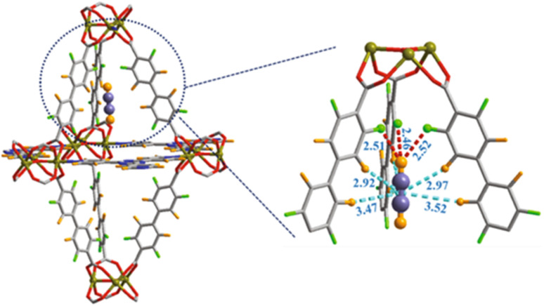
Grand-Canonical MonteCarlo Simulations (GCMCS) were also used by the authors to model the adsorption sites of acetylene molecules inside the pore walls. The preferential binding site for C2H2 molecule was found to be located in the top of a trigonal bipyramidal cage with three F atoms pointing toward the interior wall of cage. C2H2 interacts with the strong electronegative F atoms as depicted in Fig. 17.62
Fig. 17. Preferential C2H2 adsorption site calculated from GCMC simulation for JXNU-12(F). Element key: Ni (dark yellow), C (gray), F (bright green), O (red) and H (bright orange). Reproduced from ref. 62 with permission from Elsevier, copyright 2022.
The last important application of F-MOF here discussed concerns their adsorption and separation properties towards fluorocarbons and chloro-fluoro carbons (CFC).82 Such halogenated gases are harmful and critical compounds in which one or more hydrogen atoms have been replaced with fluorine and chlorine. They are commonly used as refrigerants, propellants, in the electronic industry and for their hydrophobic properties in foams.
While CFC have been banned since more than a decade, fluorocarbons are powerful greenhouse gases and they may also contribute to climate changes.83
The fully fluorinated MOF LIFM-86 reported in 2017 has been tested for application in R22/N2 separation. The IAST selectivity of R22/N2, over the parent compound LIFM-28 was increased by 6-folds, reaching a value of over 250 at zero coverage, with an isosteric heat of adsorption towards R22 of 30 kJ mol−1.
A Cu MOF based on H2BPTFM linker (2,2′-bis(trifluoromethyl)[1,1′-biphenyl]-4,4′-dicarboxylate acid), namely LIFM-100, showed an excellent selectivity towards R22 (monochlorodifluoro methane) gas over CO2 and N2.
The R22 uptake values of LIFM-100 at 1 atm are 68.7 cm3 g−1 (3.1 mmol g−1) and 34.9 cm3 g−1 (1.6 mmol g−1) at 273 and 298 K, respectively. The low coverage enthalpy of adsorption measured for this gas was 46 kJ mol−1, quite higher than that measured for CO2 (36.1 kJ mol−1 at 273 K and 21 kJ mol−1 at 298 K). IAST selectivity of LIFM-100 for a R22/N2 (10 : 90) was 399.1 at 298 K, a value higher than other reported MOFs.64
4. Conclusions
This review aimed to give an overview on the structural features and the main application of MOFs containing fluorine atoms both as anionic units or as coordinating element of a more complex inorganic units, and therefore directly linked to the structural metals or as part of fluorinated linkers used in the MOFs synthesis. Due to the strong polarization of M–F bond the first family of MOFs here discussed provided a very effective selectivity towards some guest species like CO2, thus resulting in efficient materials for direct absorption of CO2 from air or confined space. Such part of the work was mainly developed by the group of Mohamed Eddaoudi who presented several structurally related materials that have been thoroughly investigated for DAC, CO2 separation and dehydration. The second part of the review deals with F-MOFs based on fluorinated linkers. In addition, in this case the presence of fluorine was found to be crucial for increasing the affinity towards CO2, also being demonstrated by the comparison with non-fluorinated counterparts. In both cases the presence of supermicropores decorated with fluorine ions strongly enhance the affinity of such materials towards CO2 and for separation of light hydrocarbon. Another important strength of F-MOFs is their high resistance to hydrolysis and, in some cases, their enhanced hydrophobicity. Thanks to the unique features that fluorinated element, both in the inorganic and organic unit, a new route in the synthesis of MOFs for CO2 capture and separation is established, i.e., the use of fluorinated analogous linkers in the preparation of the most common MOFs. However, the main challenge in this strategy is the synthesis of the linkers that not always are commercial and at low costs. Concerning the possible impact of this research for industrial applications it can be remarked that these materials could be effectively employed for separation of gases (mainly CO2 at low concentrations) from primary emission sources both in pre- and post-combustion technology. Manufacturing of these compounds for large-scale application still requires further investigations for that concerns the cost and other issues such as the compatibility in organic polymers (gas separation mixed-membranes), preservation of the structure/properties features under pelletizing and so on.
Conflicts of interest
There are no conflicts to declare.
Supplementary Material
Acknowledgments
Authors acknowledge the Italian MUR through the Project PRIN 2020 doMino (ref. 2020P9KBKZ).
Notes and references
- Colglazier W. Science. 2015;349(6252):1048. doi: 10.1126/science.aad2333. [DOI] [PubMed] [Google Scholar]
- Freund R. Zaremba O. Arnauts G. Ameloot R. Skorupskii G. Dincă M. Bavykina A. Gascon J. Ejsmont A. Goscianska J. Kalmutzki M. Lächelt U. Ploetz E. Diercks C. S. Wuttke S. Angew. Chem., Int. Ed. 2021;60(45):23975. doi: 10.1002/anie.202106259. [DOI] [PubMed] [Google Scholar]
- Petit C. Curr. Opin. Chem. Eng. 2018;20:132. [Google Scholar]
- Ghanbari T. Abnisa F. Daud W. Ashri W. M. Sci. Total Environ. 2020;707:135090. doi: 10.1016/j.scitotenv.2019.135090. [DOI] [PubMed] [Google Scholar]
- Burd S. D. Ma S. Perman J. A. Sikora B. J. Snurr R. Q. Thallapally P. K. Tian J. Wojtas L. Zaworotko M. J. J. Am. Chem. Soc. 2012;134(8):3663. doi: 10.1021/ja211340t. [DOI] [PubMed] [Google Scholar]
- Sadiq M. M. Batten M. P. Mulet X. Freeman C. Konstas K. Mardel J. I. Tanner J. Ng D. Wang X. Howard S. Hill M. R. Thornton A. W. Adv. Sustainable Syst. 2020;4(12):2000101. [Google Scholar]
- Belmabkhout Y. Guillerm V. Eddaoudi M. Chem. Eng. J. 2016;296:386. [Google Scholar]
- Taddei M. Petit C. Mol. Syst. Des. Eng. 2021;6(11):841. [Google Scholar]
- Liang W. Bhatt P. M. Shkurenko A. Adil K. Mouchaham G. Aggarwal H. Mallick A. Jamal A. Belmabkhout Y. Eddaoudi M. Chem. 2019;5(4):950. [Google Scholar]
- Gargiulo N. Peluso A. Aprea P. Marino O. Cioffi R. Jannelli E. Cimino S. Lisi L. Caputo D. Renewable Energy. 2019;138:230. [Google Scholar]
- Demir H. Cramer C. J. Siepmann J. I. Mol. Syst. Des. Eng. 2019;4(6):1125. [Google Scholar]
- Nugent P. Belmabkhout Y. Burd S. D. Cairns A. J. Luebke R. Forrest K. Pham T. Ma S. Space B. Wojtas L. Eddaoudi M. Zaworotko M. J. Nature. 2013;495(7439):80. doi: 10.1038/nature11893. [DOI] [PubMed] [Google Scholar]
- Ye Y. Ma Z. Lin R.-B. Krishna R. Zhou W. Lin Q. Zhang Z. Xiang S. Chen B. J. Am. Chem. Soc. 2019;141(9):4130. doi: 10.1021/jacs.9b00232. [DOI] [PMC free article] [PubMed] [Google Scholar]
- Kim H. Yang S. Rao S. R. Narayanan S. Kapustin E. A. Furukawa H. Umans A. S. Yaghi O. M. Wang E. N. Science. 2017;356(6336):430. doi: 10.1126/science.aam8743. [DOI] [PubMed] [Google Scholar]
- Xu W. Yaghi O. M. ACS Cent. Sci. 2020;6(8):1348. doi: 10.1021/acscentsci.0c00678. [DOI] [PMC free article] [PubMed] [Google Scholar]
- Wang Q. Astruc D. Chem. Rev. 2020;120(2):1438. doi: 10.1021/acs.chemrev.9b00223. [DOI] [PubMed] [Google Scholar]
- Liu M. Wu J. Hou H. Chemistry. 2019;25(12):2935. doi: 10.1002/chem.201804149. [DOI] [PubMed] [Google Scholar]
- Xia Y.-S. Tang M. Zhang L. Liu J. Jiang C. Gao G.-K. Dong L.-Z. Xie L.-G. Lan Y.-Q. Nat. Commun. 2022;13(1):2964. doi: 10.1038/s41467-022-30676-y. [DOI] [PMC free article] [PubMed] [Google Scholar]
- Wei T. Wang Z. Zhang Q. Zhou Y. Sun C. Wang M. Liu Y. Wang S. Yu Z. Qiu X. Xu S. Qin S. CrystEngComm. 2022;24(28):5014. [Google Scholar]
- Lin J. Li N. Yang S. Jia M. Liu J. Li X.-M. An L. Tian Q. Dong L.-Z. Lan Y.-Q. J. Am. Chem. Soc. 2020;142(32):13982. doi: 10.1021/jacs.0c06582. [DOI] [PubMed] [Google Scholar]
- Wang R. Liu J. Huang Q. Dong L.-Z. Li S.-L. Lan Y.-Q. Angew. Chem., Int. Ed. Engl. 2021;60(36):19829. doi: 10.1002/anie.202105343. [DOI] [PubMed] [Google Scholar]
- Brambilla A. Gasparri E. Zolfaghari L. Keshavarzi R. Andaloro A. J. Cleaner Prod. 2022;366(1):132809. [Google Scholar]
- Dziejarski B. Krzyżyńska R. Andersson K. Fuel. 2023;342(7):127776. [Google Scholar]
- Noro S.-i. Nakamura T. NPG Asia Mater. 2017;9(9):e433. [Google Scholar]
- Ebadi Amooghin A. Sanaeepur H. Luque R. Garcia H. Chen B. Chem. Soc. Rev. 2022;51(17):7427. doi: 10.1039/d2cs00442a. [DOI] [PubMed] [Google Scholar]
- Bhatt P. M. Guillerm V. Datta S. J. Shkurenko A. Eddaoudi M. Chem. 2020;6(7):1613. [Google Scholar]
- Mukherjee S. Kansara A. M. Saha D. Gonnade R. Mullangi D. Manna B. Desai A. V. Thorat S. H. Singh P. S. Mukherjee A. Ghosh S. K. Chemistry. 2016;22(31):10937. doi: 10.1002/chem.201601724. [DOI] [PubMed] [Google Scholar]
- Tchalala M. R. Bhatt P. M. Chappanda K. N. Tavares S. R. Adil K. Belmabkhout Y. Shkurenko A. Cadiau A. Heymans N. de Weireld G. Maurin G. Salama K. N. Eddaoudi M. Nat. Commun. 2019;10(1):1328. doi: 10.1038/s41467-019-09157-2. [DOI] [PMC free article] [PubMed] [Google Scholar]
- D'Amato R. Donnadio A. Carta M. Sangregorio C. Tiana D. Vivani R. Taddei M. Costantino F. ACS Sustainable Chem. Eng. 2019;7(1):394. [Google Scholar]
- Venturi D. M. Notari M. S. Bondi R. Mosconi E. Kaiser W. Mercuri G. Giambastiani G. Rossin A. Taddei M. Costantino F. ACS Appl. Mater. Interfaces. 2022;14(36):40801. doi: 10.1021/acsami.2c07640. [DOI] [PMC free article] [PubMed] [Google Scholar]
- Liu G. Cadiau A. Liu Y. Adil K. Chernikova V. Carja I.-D. Belmabkhout Y. Karunakaran M. Shekhah O. Zhang C. Itta A. K. Yi S. Eddaoudi M. Koros W. J. Angew. Chem. 2018;130(45):15027. doi: 10.1002/anie.201808991. [DOI] [PubMed] [Google Scholar]
- Krüger M. Reinsch H. Inge A. K. Stock N. Microporous Mesoporous Mater. 2017;249:128. [Google Scholar]
- Chang G. Wen H. Li B. Zhou W. Wang H. Alfooty K. Bao Z. Chen B. Cryst. Growth Des. 2016;16(6):3395. [Google Scholar]
- Skarmoutsos I. Eddaoudi M. Maurin G. Microporous Mesoporous Mater. 2019;281:44. [Google Scholar]
- Shekhah O. Belmabkhout Y. Adil K. Bhatt P. M. Cairns A. J. Eddaoudi M. Chem. Commun. 2015;51(71):13595. doi: 10.1039/c5cc04487a. [DOI] [PubMed] [Google Scholar]
- Chernikova V. Shekhah O. Belmabkhout Y. Eddaoudi M. ACS Appl. Nano Mater. 2020;3(7):6432. [Google Scholar]
- Limburg B. Cristòfol À. Della Monica F. Kleij A. W. ChemSusChem. 2020;13(23):6056. doi: 10.1002/cssc.202002246. [DOI] [PubMed] [Google Scholar]
- Joharian M. Morsali A. Azhdari Tehrani A. Carlucci L. Proserpio D. M. Green Chem. 2018;20(23):5336. [Google Scholar]
- Cadiau A. Belmabkhout Y. Adil K. Bhatt P. M. Pillai R. S. Shkurenko A. Martineau-Corcos C. Maurin G. Eddaoudi M. Science. 2017;356(6339):731. doi: 10.1126/science.aam8310. [DOI] [PubMed] [Google Scholar]
- Palakkal A. S. Pillai R. S. J. Phys. Chem. C. 2020;124(31):16975. [Google Scholar]
- Lusi M. Fechine P. B. A. Chen K.-J. Perry J. J. Zaworotko M. J. Chem. Commun. 2016;52(22):4160. doi: 10.1039/c5cc10203k. [DOI] [PubMed] [Google Scholar]
- Jiang Y. Hu Y. Luan B. Wang L. Krishna R. Ni H. Hu X. Zhang Y. Nat. Commun. 2023;14(1):401. doi: 10.1038/s41467-023-35984-5. [DOI] [PMC free article] [PubMed] [Google Scholar]
- Winarta J. Shan B. Mcintyre S. M. Ye L. Wang C. Liu J. Mu B. Cryst. Growth Des. 2020;20(2):1347. [Google Scholar]
- Vizuet J. P. Mortensen M. L. Lewis A. L. Wunch M. A. Firouzi H. R. McCandless G. T. Balkus K. J. J. Am. Chem. Soc. 2021;143(43):17995. doi: 10.1021/jacs.1c10493. [DOI] [PubMed] [Google Scholar]
- Prasetyo N. Pambudi F. I. Int. J. Hydrogen Energy. 2021;46(5):4222. [Google Scholar]
- Nguyen T. T. Nguyen-Minh Le T. Nguyen T. T. Phan T. B. Nguyen-Manh D. Int. J. Hydrogen Energy. 2023;48(24):8997. [Google Scholar]
- Pachfule P. Dey C. Panda T. Banerjee R. CrystEngComm. 2010;12(5):1600. [Google Scholar]
- Yang L. Yan L. Niu W. Feng Y. Fu Q. Zhang S. Zhang Y. Li L. Gu X. Dai P. Liu D. Zheng Q. Zhao X. Angew. Chem., Int. Ed. Engl. 2022;61(25):e202204046. doi: 10.1002/anie.202204046. [DOI] [PubMed] [Google Scholar]
- Zhang L. Jee S. Park J. Jung M. Wallacher D. Franz A. Lee W. Yoon M. Choi K. Hirscher M. Oh H. J. Am. Chem. Soc. 2019;141(50):19850. doi: 10.1021/jacs.9b10268. [DOI] [PMC free article] [PubMed] [Google Scholar]
- Chen T.-H. Popov I. Zenasni O. Daugulis O. Miljanić O. Š. Chem. Commun. 2013;49(61):6846. doi: 10.1039/c3cc41564c. [DOI] [PubMed] [Google Scholar]
- Qiu Q. f. Chen C. X. Zeng Z. Wei Z. W. Cao C. C. Wang W. Wang D. Wang H. P. Jiang J. J. Inorg. Chem. 2020;59(20):14856. doi: 10.1021/acs.inorgchem.0c02123. [DOI] [PubMed] [Google Scholar]
- Chen C.-X. Wei Z.-W. Jiang J.-J. Zheng S.-P. Wang H.-P. Qiu Q.-F. Cao C.-C. Fenske D. Su C.-Y. J. Am. Chem. Soc. 2017;139(17):6034. doi: 10.1021/jacs.7b01320. [DOI] [PubMed] [Google Scholar]
- Biswas S. Rémy T. Couck S. Denysenko D. Rampelberg G. Denayer J. F. M. Volkmer D. Detavernier C. van der Voort P. Phys. Chem. Chem. Phys. 2013;15(10):3552. doi: 10.1039/c3cp44204g. [DOI] [PubMed] [Google Scholar]
- Bhatt P. M. Belmabkhout Y. Cadiau A. Adil K. Shekhah O. Shkurenko A. Barbour L. J. Eddaoudi M. J. Am. Chem. Soc. 2016;138(29):9301. doi: 10.1021/jacs.6b05345. [DOI] [PubMed] [Google Scholar]
- Zhang W. Zhang J. Dong X. Li M. He Q. Zhao S. Xie L. Chem. Eng. J. 2023;461(13):142058. [Google Scholar]
- Yu M.-H. Fang H. Huang H.-L. Zhao M. Su Z.-Y. Nie H.-X. Chang Z. Hu T.-L. Small. 2023;19(22):e2300821. doi: 10.1002/smll.202300821. [DOI] [PubMed] [Google Scholar]
- Shearan S. J. I. Jacobsen J. Costantino F. D'Amato R. Novikov D. Stock N. Andreoli E. Taddei M. Chemistry. 2021;27(21):6579. doi: 10.1002/chem.202005085. [DOI] [PubMed] [Google Scholar]
- Cavallo M. Atzori C. Signorile M. Costantino F. Venturi D. M. Koutsianos A. Lomachenko K. A. Calucci L. Martini F. Giovanelli A. Geppi M. Crocellà V. Taddei M. J. Mater. Chem. A. 2023;11(11):5568. doi: 10.1039/d2ta09746j. [DOI] [PMC free article] [PubMed] [Google Scholar]
- Wang H. Lu S. Liu Q. Han R. Lu X. Song C. Ji N. Ma D. ChemSusChem. 2022;15(16):e202200702. doi: 10.1002/cssc.202200702. [DOI] [PubMed] [Google Scholar]
- Morelli Venturi D. Guiotto V. D'Amato R. Calucci L. Signorile M. Taddei M. Crocellà V. Costantino F. Mol. Syst. Des. Eng. 2023;8(5):586. [Google Scholar]
- Perego J. Bezuidenhout C. X. Bracco S. Piva S. Prando G. Aloisi C. Carretta P. Kaleta J. Le T. P. Sozzani P. Daolio A. Comotti A. Angew. Chem., Int. Ed. Engl. 2023;62(5):e202215893. doi: 10.1002/anie.202215893. [DOI] [PubMed] [Google Scholar]
- Fu X.-P. Wang Y.-L. Zhang X.-F. Krishna R. He C.-T. Liu Q.-Y. Chen B. Chem. Eng. J. 2022;432(9):134433. [Google Scholar]
- Chen T.-H. Popov I. Kaveevivitchai W. Chuang Y.-C. Chen Y.-S. Jacobson A. J. Miljanić O. Š. Angew. Chem., Int. Ed. Engl. 2015;54(47):13902. doi: 10.1002/anie.201505149. [DOI] [PubMed] [Google Scholar]
- Qiu Q.-F. Chen C.-X. Zeng Z. Wei Z.-W. Zhu N.-X. Cao C.-C. Wang W. Wang D. Wang H.-P. Jiang J.-J. Inorg. Chem. 2020;59(20):14856. doi: 10.1021/acs.inorgchem.0c02123. [DOI] [PubMed] [Google Scholar]
- Zhao D. Yu C. Jiang J. Duan X. Zhang L. Jiang K. Qian G. J. Solid State Chem. 2019;277:139. [Google Scholar]
- Wu X.-Q. Liu J.-H. He T. Zhang P.-D. Yu J. Li J.-R. Chem. Eng. J. 2021;407(10):127183. [Google Scholar]
- Xue D.-X. Cairns A. J. Belmabkhout Y. Wojtas L. Liu Y. Alkordi M. H. Eddaoudi M. J. Am. Chem. Soc. 2013;135(20):7660. doi: 10.1021/ja401429x. [DOI] [PubMed] [Google Scholar]
- Perego J. Bezuidenhout C. X. Pedrini A. Bracco S. Negroni M. Comotti A. Sozzani P. J. Mater. Chem. A. 2020;8(22):11406. [Google Scholar]
- Chen K.-J. Scott H. S. Madden D. G. Pham T. Kumar A. Bajpai A. Lusi M. Forrest K. A. Space B. Perry J. J. Zaworotko M. J. Chem. 2016;1(5):753. [Google Scholar]
- Guerrero-Pérez M. O. Bañares M. A. Catal. Today. 2015;239(2):25. [Google Scholar]
- Buitelaar M. M. van Daatselaar E. van Teijlingen D. G. Stokvis H. I. Wendt J. D. de Sousa Ribeiro R. J. Brooks A. M. M. Kamphuis E. C. Lopez Montoya S. van Putten J. C. van der Ham A. G. J. van den Berg H. Lange J.-P. Ind. Eng. Chem. Res. 2020;59(3):1183. [Google Scholar]
- Gao M.-Y. Bezrukov A. A. Song B.-Q. He M. Nikkhah S. J. Wang S.-Q. Kumar N. Darwish S. Sensharma D. Deng C. Li J. Liu L. Krishna R. Vandichel M. Yang S. Zaworotko M. J. J. Am. Chem. Soc. 2023;145(21):11837. doi: 10.1021/jacs.3c03505. [DOI] [PMC free article] [PubMed] [Google Scholar]
- Jiang Y. Hu J. Wang L. Sun W. Xu N. Krishna R. Duttwyler S. Cui X. Xing H. Zhang Y. Angew. Chem., Int. Ed. Engl. 2022;61(18):e202200947. doi: 10.1002/anie.202200947. [DOI] [PubMed] [Google Scholar]
- Cui W.-G. Hu T.-L. Bu X.-H. Adv. Mater. 2020;32(3):e1806445. doi: 10.1002/adma.201806445. [DOI] [PubMed] [Google Scholar]
- Li Y.-Z. Wang H.-H. Wang G.-D. Hou L. Wang Y.-Y. Zhu Z. Inorg. Chem. Front. 2021;8(2):376. [Google Scholar]
- Chen C.-X. Wei Z.-W. Pham T. Lan P. C. Zhang L. Forrest K. A. Chen S. Al-Enizi A. M. Nafady A. Su C.-Y. Ma S. Angew. Chem., Int. Ed. Engl. 2021;60(17):9680. doi: 10.1002/anie.202100114. [DOI] [PubMed] [Google Scholar]
- Fan W. Yuan S. Wang W. Feng L. Liu X. Zhang X. Wang X. Kang Z. Dai F. Yuan D. Sun D. Zhou H.-C. J. Am. Chem. Soc. 2020;142(19):8728. doi: 10.1021/jacs.0c00805. [DOI] [PubMed] [Google Scholar]
- Zhang Z. Peh S. B. Krishna R. Kang C. Chai K. Wang Y. Shi D. Zhao D. Angew. Chem., Int. Ed. Engl. 2021;60(31):17198. doi: 10.1002/anie.202106769. [DOI] [PubMed] [Google Scholar]
- Belmabkhout Y. Zhang Z. Adil K. Bhatt P. M. Cadiau A. Solovyeva V. Xing H. Eddaoudi M. Chem. Eng. J. 2019;359(26):32. [Google Scholar]
- Mukherjee S. Kumar N. Bezrukov A. A. Tan K. Pham T. Forrest K. A. Oyekan K. A. Qazvini O. T. Madden D. G. Space B. Zaworotko M. J. Angew. Chem., Int. Ed. Engl. 2021;60(19):10902. doi: 10.1002/anie.202100240. [DOI] [PMC free article] [PubMed] [Google Scholar]
- Wen H.-M. Li L. Lin R.-B. Li B. Hu B. Zhou W. Hu J. Chen B. J. Mater. Chem. A. 2018;6(16):6931. [Google Scholar]
- Yancey A. D. Terian S. J. Shaw B. J. Bish T. M. Corbin D. R. Shiflett M. B. Microporous Mesoporous Mater. 2022;331:111654. [Google Scholar]
- Motkuri R. K. Annapureddy H. V. R. Vijaykumar M. Schaef H. T. Martin P. F. McGrail B. P. Dang L. X. Krishna R. Thallapally P. K. Nat. Commun. 2014;5:4368. doi: 10.1038/ncomms5368. [DOI] [PubMed] [Google Scholar]


