

Abstract
The electrocatalytic nitrate (NO3–) reduction reaction (eNITRR) is a promising method for ammonia synthesis. However, its efficacy is currently limited due to poor selectivity, largely caused by the inherent complexity of the multiple-electron processes involved. To address these issues, oxygen-vacancy-rich LaFe0.9M0.1O3−δ (M = Co, Ni, and Cu) perovskite submicrofibers have been designed from the starting material LaFeO3−δ (LF) by a B-site substitution strategy and used as the eNITRR electrocatalyst. Consequently, the LaFe0.9Cu0.1O3−δ (LF0.9Cu0.1) submicrofibers with a stronger Fe–O hybridization, more oxygen vacancies, and more positive surface potential exhibit a higher ammonia yield rate of 349 ± 15 μg h–1 mg–1cat. and a Faradaic efficiency of 48 ± 2% than LF submicrofibers. The COMSOL Multiphysics simulations demonstrate that the more positive surface of LF0.9Cu0.1 submicrofibers can induce NO3– enrichment and suppress the competing hydrogen evolution reaction. By combining a variety of in situ characterizations and density functional theory calculations, the eNITRR mechanism is revealed, where the first proton–electron coupling step (*NO3 + H+ + e– → *HNO3) is the rate-determining step with a reduced energy barrier of 1.83 eV. This work highlights the positive effect of cation substitution in promoting eNITRR properties of perovskites and provides new insights into the studies of perovskite-type electrocatalytic ammonia synthesis catalysts.
1. Introduction
Ammonia (NH3), an essential chemical in the nitrogen cycle network, is a fundamental compound for human beings that has been widely used as a nitrogen source for the synthesis of fertilizers, explosives, plastics, and so on.1 Currently, NH3 is mainly produced via the energy-intensive Haber–Bosch process under harsh conditions (300–500 °C, 200–300 bar),2 accompanied by an abundant amount of greenhouse gas emissions (the global average is 2.86 tons of carbon dioxide per ton of NH3).3 Thus, alternative approaches such as the electrocatalytic nitrogen reduction reaction (eNRR) under mild operating conditions have become more popular in recent years.4–8 Recent research indicates that metals, alloys, nitrides, oxides, and carbides can function as potential eNRR catalysts.9 Despite significant achievements in recent years, the eNRR still suffers from low Faradaic efficiencies (FEs, mostly <30%) and limited NH3 yield rates (mostly <200 μg h–1 mg–1cat.).9,10 These challenges arise from the extremely stable N≡N triple bond with a bond energy of 941 kJ mol–1, the low solubility of N2 gas in aqueous electrolytes, and the competing hydrogen evolution reaction (HER).11–13 Owning to the high solubility (the solubility of NaNO3 is 87.6 g in 100 mL of water at 293 K) and the weak N=O double bond (binding energy of 204 kJ mol–1) of nitrate (NO3–), the electrocatalytic nitrate reduction reaction (eNITRR) has emerged as an alternative technology to the eNRR process that can improve both the NH3 yield rate and the FE.14,15 The NO3– ion is a pollutant found in many types of wastewaters.16–19 Therefore, finding ways to use it by the eNITRR can also tackle environmental issues simultaneously. However, designing advanced electrocatalysts with high selectivity for transforming NO3– to NH3via the eNITRR remains a challenge because the eNITRR is a complicated 8e– transfer reaction involving many intermediates (e.g., NO2, NO, N2O, N2, NH2OH, NH3, and NH2NH2).15 Among the various eNITRR electrocatalysts, Cu-containing catalysts demonstrate superior performance compared to other catalysts.20 However, the issue of instability in copper-containing catalysts limits their applications, which has also sparked research interest in the reaction mechanism of Cu-containing catalysts and the design of highly stable Cu-containing catalysts. For instance, extensive research has been conducted on various aspects, such as regulating the d-band center of Cu-containing catalysts,14 the electrochemical restructuring of Cu-containing catalysts,20–22 and the synergistic effects between Cu and other metals.23,24 Nonetheless, addressing the stability concern associated with Cu still poses a significant challenge.
The previous search for cost-effective and efficient eNITRR catalysts has revealed the potential of perovskite oxides owing to their flexible electronic structures and chemical versatility.25–27 Perovskite oxides (ABO3, where the A-site cations are alkaline-earth or rare-earth metals and B-site cations are transition metals) are conventionally prepared by ball milling or sol–gel methods, resulting in an uncontrollable and blocked structure with severe particle agglomeration.28,29 Generally, it has been demonstrated that exposing accessible active sites of perovskite oxides by constructing specific geometrical structures, such as SrNb0.1Co0.7Fe0.2O3−δ nanorods,30 BiFeO3 nanosheets,31 NaNbO3 nanocubes,32 and so on, can result in a highly efficient electrocatalytic process. Among them, the cross-linked network woven by one-dimensional (1D) perovskite oxide submicrofibers can not only facilitate reactant diffusion and electron transport during the electrocatalytic process but also avoid particle agglomeration to expose the maximum number of active sites for the adsorption and reduction of NO3– ions. In addition to the construction of the unique structure, the activity of the perovskite is also affected by the electronic environment around the active sites.33 As the perovskite oxides can accommodate ∼90% of metallic elements of the periodic table, their high compositional flexibility enables the incorporation of metal elements to form a B-site bimetallic perovskite. Based on the molecular orbital theory and band theory, the catalytic performance of perovskite oxides can be influenced by tailoring the octahedral structure of their [BO6] units, regulating the hybridization of B–O bonds, and generating oxygen vacancies (OVs). For example, the covalency of transition metal–oxygen bonds, which reflects the adsorption strength of oxygen-related intermediates, was verified to be an important descriptor for electrocatalytic activity.28,34 Therefore, it is rational to optimize the adsorption strength of intermediates in the eNITRR process by substituting the B-site cation with other elements. Apart from the variation of the electronic structure, the B-site cation substitution strategy will also affect the work function of the catalyst surface, which is accompanied by a change in surface potential.35,36 The surface potential and corresponding work function play important roles in facilitating the transport of electrons from the catalyst to the reactant.
Inspired by the Fe active sites in both Haber–Bosch catalysts (Fe-based compounds) and nitrogenase enzymes (mainly containing the Fe–Mo cofactor), a series of Fe-rich perovskite oxides of LaFe0.9M0.1O3−δ (M = Co, Ni, and Cu) submicrofibers (noted as LF0.9Co0.1, LF0.9Ni0.1, and LF0.9Cu0.1 submicrofibers, respectively) were constructed by a B-site substitution strategy and acted as the eNITRR electrocatalysts. The LF0.9Cu0.1 submicrofibers showed a higher NH3 yield rate of 349 ± 15 μg h–1 mg–1cat. and a higher FE of 48 ± 2% than the parent LF submicrofibers, which are attributed to the inhomogeneous charge redistribution and abundant OVs on the surface of LF0.9Cu0.1 submicrofibers, as well as its more positive surface potential and lower work function for achieving an enhanced adsorption ability toward NO3– ions. COMSOL Multiphysics simulations also confirm this discovery from the perspective of a theoretical calculation. The reaction mechanism was investigated in detail by combining operando Fourier transform infrared (FT-IR) spectroscopy, online differential electrochemical mass spectrometry (DEMS), and density functional theory (DFT) calculations. In the deoxidation process of the reaction stages, the first proton–electron coupling step of *NO3 + H+ + e– → *HNO3 is the rate-determining step (RDS). The substitution of Cu in the B site lowers the barrier energy in this step, thereby facilitating the reaction.
2. Results and Discussion
The LaFeO3 (LF) and LF0.9M0.1 (M = Co, Ni, and Cu) submicrofibers were synthesized via an electrospinning technique followed by calcination, as illustrated in Figure 1a. In a typical procedure, the metal precursors as nitrate salts and polyvinylpyrrolidone were dissolved in N,N-dimethylformamide to form a homogeneous, viscous solution, which was used for the electrospinning process. Subsequently, the electrospun metal salt–polymer submicrofibers were calcined to generate 1D perovskite oxide submicrofibers (more experimental details can be found in the Supporting Information). As the scanning electron microscopy (SEM) images show in Figures 1b and S1, all these samples consist of 1D submicrofibers without obvious fracture or aggregation. As an example, LF0.9Cu0.1 submicrofibers are stacked layer-by-layer and connected to form three-dimensional networks (Figure 1b), with an average diameter of approximately 250 nm (Figure S2). Notably, the LF0.9Cu0.1 submicrofiber was generated by concatenating abundant LF0.9Cu0.1 nanoparticles, with diameters ranging between 50 and 70 nm, into an integrated structure. This is evident from the transmission electron microscopy (TEM) image (Figure 1c). The high-resolution TEM (HRTEM) image of LF0.9Cu0.1 shows clear crystal fringes with a lattice spacing of ∼0.27 nm, which belongs to the (121) plane of the perovskite oxide (Figure 1d). Moreover, the energy-dispersive X-ray spectroscopy (EDX) mappings of LF0.9Cu0.1 submicrofibers (Figure 1e) show that La, Fe, O, and Cu elements are dispersed throughout the nanostructure homogeneously. The perovskite crystal phases of LF, LF0.9Co0.1, LF0.9Ni0.1, and LF0.9Cu0.1 submicrofibers were verified by X-ray diffraction (XRD) patterns, as shown in Figure S3. All samples display clear diffraction peaks at 22.6, 25.3, 32.2, 39.7, 46.1, 47.6, 52.0, 53.3, 57.4, 67.3, and 76.7°, which can be indexed to the (101), (111), (121), (220), (202), (212), (103), (311), (123), (242), and (204) planes, respectively, of orthorhombic perovskite structures (JCPDS 88–0641) without any impurity phase. It should be noted that the diffraction peaks would shift slightly after cationic substitution, such as the (121) peak, which may imply the lattice variation due to the cation substitution.37 The crystal structures were further confirmed by Rietveld refinement of the XRD patterns (Figure S4) in Table S1. By taking LF0.9Cu0.1 as an example, the decrease in unit cell volume indicates that the substitution of Cu caused lattice shrinkage due to the reduced ionic radii of Cu2+ ions. The atomic ratios of Fe/M in LF0.9Co0.1, LF0.9Ni0.1, and LF0.9Cu0.1 submicrofibers were also checked to be approximately 9:1 by inductively coupled plasma mass spectrometry (ICP–MS) (Table S2). In short, the 1D perovskite submicrofibers formed by the directional accumulation of nanoparticles with tunable B-site bimetallic cations were successfully synthesized by the electrospinning technique and calcination process.
Figure 1.

(a) Schematic illustration for the synthetic process of 1D perovskite submicrofibers. (b) SEM image, (c) TEM image, (d) HRTEM image, and (e) EDX mappings of LF0.9Cu0.1 submicrofibers.
The eNITRR performance of various perovskite submicrofibers was evaluated in an H-type electrolytic cell under ambient conditions, where 0.5 M Na2SO4 with 50 ppm NO3––N (NO3––N represents the concentration of NO3– expressed in terms of the nitrogen content) aqueous solution was used as the electrolyte. The concentrations of reactant NO3–, reductive product NH3, and byproduct nitrite (NO2–) were detected using colorimetric methods (Figures S5–S7).38–40 The linear sweep voltammetry (LSV) curves of LF0.9Cu0.1 submicrofibers in 0.5 M Na2SO4 electrolytes with and without NO3– were recorded to investigate the potential window for the eNITRR process. When the potential is more negative than −0.6 V vs the reversible hydrogen electrode (RHE), the current density for the LSV curve with NO3– is enhanced significantly (Figure 2a), suggesting the occurrence of the eNITRR process. Figure 2b shows the time-dependent current density curves of LF0.9Cu0.1 submicrofibers at different working potentials. The negligible decay in current density indicates the considerable catalytic stability of LF0.9Cu0.1 submicrofibers. From the summarized FE values and NH3 yield rates for various samples (LF, LF0.9Co0.1, LF0.9Ni0.1, and LF0.9Cu0.1) in Figures 2c,d, S8, and S9, the FEs for NH3 of these samples follow a volcano-type trend as a function of applied potentials. This phenomenon can be attributed to the increased competition from the HER at more negative potentials, coupled with a decrease in the available charges at more positive potentials. Notably, the LF0.9Cu0.1 submicrofibers exhibit the best eNITRR performance with a maximal FE value of 48 ± 2% and a high NH3 yield rate of 349 ± 15 μg h–1 mg–1cat. at −0.90 V vs RHE. Additionally, the 1H nuclear magnetic resonance method (Figure S10) was also conducted as another quantitative measurement to check the NH3 yield rates for all electrocatalysts at a potential of −0.9 V vs RHE, which are in good agreement with the results by the UV–vis spectroscopy method (Figure S11). The N-selectivity indicates the ratio of NH4+–N in converted NO3––N, and is an important parameter that reflects the degree of conversion from NO3– to NH4+. By testing the NO3– concentrations for various samples after 2 h eNITRR processes at −0.9 V vs RHE, it can be observed that all the perovskite oxides display high N-selectivities of NH3 of over 80% (Figure 2e), which are comparable to or better than other reports for NO3– electroreduction (Table S3). The N-selectivities of the four samples for NO2– are close to 20%, indicating that their main soluble byproduct is NO2– (Figure S12). To evaluate the eNITRR performance of LF0.9Cu0.1 comprehensively, the NH3 yield rates and FEs at different concentrations were also measured. The results, as depicted in Figure S13, demonstrate that the catalyst maintains high catalytic activity even at higher concentrations.
Figure 2.

(a) LSV curves of LF0.9Cu0.1 submicrofibers in 0.5 M Na2SO4 electrolyte with and without NO3–. (b) Time-dependent current density curves of the LF0.9Cu0.1 submicrofibers against various work potentials. (c) FE values of LF and LF0.9Cu0.1 submicrofibers at each given potential. (d) NH3 yield rates and (e) N selectivities of LF and LF0.9M0.1 (M = Co, Ni, and Cu) submicrofibers at −0.9 V vs RHE. (f) Cycling tests of LF0.9Cu0.1 submicrofibers at −0.9 V vs RHE.
To exclude the interference from the electrocatalyst itself or the external environment, a comparison test was performed in 0.5 M Na2SO4 electrolyte without NO3–. As shown in Figure S14, no NH3 can be detected, which indicates that the produced NH3 during the eNITRR process originates from the NO3– ions in the Na2SO4 electrolyte. Furthermore, the electrocatalytic and structural stabilities of the LF0.9Cu0.1 submicrofibers were evaluated by 6 consecutive electrolysis cycles at −0.9 V vs RHE. As shown in Figure 2f, the NH3 yield rate and FE value of each cycle fluctuate slightly but remain stable, suggesting the excellent electrocatalytic stability of LF0.9Cu0.1 submicrofibers for potential practical applications. The perovskite structure of LF0.9Cu0.1 submicrofibers is also maintained well based on the XRD pattern of LF0.9Cu0.1/carbon paper after the eNITRR process (Figure S15), which illustrates the excellent structural stability of LF0.9Cu0.1 submicrofibers. ICP–MS was employed for the evaluation of changes in the composition of LF0.9Cu0.1 submicrofibers after the stability test. The results show that no significant changes have occurred in the composition of the catalyst, further highlighting its excellent stability (Table S4). Figure S16 shows the Nyquist plots of the LF and LF0.9Cu0.1 submicrofibers. The charge transfer resistance of LF0.9Cu0.1 (28.6 ± 3.9 Ω) is smaller than that of LF (40.0 ± 3.0 Ω), which indicates that the electron transfer rate is faster in LF0.9Cu0.1. To investigate the influence of active sites on the eNITRR, we calculated the electrochemically active surface areas (ECSAs) of LF and LF0.9Cu0.1. As shown in Figures S17 and S18, the double-layer capacitance of LF0.9Cu0.1 is 0.31 mF cm–2, which is almost equal to that of LF at 0.27 mF cm–2. Based on this, the activity gap between LF and LF0.9Cu0.1 was not strongly correlated with the ECSA.
The valence state and electronic structural information were explored by X-ray photoelectron spectroscopy (XPS) and synchrotron-based X-ray absorption spectroscopy (XAS) techniques. Figure 3a shows Fe 2p XPS spectra of LF and LF0.9Cu0.1 submicrofibers, and the peaks at 710.2 eV (Fe2+ 2p3/2), 712.1 eV (Fe3+ 2p3/2), 723.7 eV (Fe2+ 2p1/2), and 725.5 eV (Fe3+ 2p1/2) indicate the coexistence of Fe2+ and Fe3+.41,42 The Fe3+/Fe2+ ratio increases with the substitution of low-valent Cu atoms in LF because more Fe3+ ions are required to balance the charges (Table S5).43 This phenomenon also illustrates the charge redistribution in LF as a result of the cation substitution strategy.44 Moreover, the valence state of Fe is influenced by the filling degree of the d orbitals, thereby determining the d-band center of the catalyst. Therefore, the value for the d-band center of the Fe element becomes more positive with the increase of its valence state, leading to an enhanced adsorption of NO3– ions.45 The Fe coordination environments of LF and LF0.9Cu0.1 were also investigated by synchrotron-based XAS measurements. The X-ray absorption near-edge structure (XANES) spectra of LF, LF0.9Cu0.1, standard Fe2O3, standard FeO, and Fe foil are shown in Figure 3b. The Fe K-edge XANES spectra of LF and LF0.9Cu0.1 are found to be between those of FeO and Fe2O3, suggesting that their average valence states of Fe are both between +2 and +3. Meanwhile, XANES spectra of Fe in LF0.9Cu0.1 has a higher energy than that in LF, indicating that the valence state of Fe in LF0.9Cu0.1 is slightly higher than that in LF,46 which is consistent with the XPS results. The Fourier transform extended X-ray absorption fine structure (FT-EXAFS) spectra in R-space for LF and LF0.9Cu0.1 are shown in Figure 3c. There are three prominent peaks at about 1.5, 3.0, and 3.5 Å for LF and LF0.9Cu0.1 that originate from the scattering paths of the Fe–O, La–Fe, and Fe–O–Fe bonds,47 respectively. With partial Fe atoms substituted by Cu atoms, the length of the Fe–O bond decreases and indicates an enhanced hybridization of the Fe 3d–O 2p orbitals.48 The wavelet transform (WT)-EXAFS measurements were also used to provide insights into the coordination structures of Fe atoms in LF and LF0.9Cu0.1 (Figures 3d,e and S19). The maximum intensity is closely associated with the path length, which can provide pivotal clues for identifying the coordination environment. Specifically, the scattering path signals at [χ(R), χ(k)] of [1.56, 7.0] and [1.50, 6.9] are associated with Fe–O bonds in the LF and LF0.9Cu0.1 submicrofibers, respectively. The second set of WT-EXAFS peaks at [3.0, 7.9] and [3.0, 7.8] can be assigned to the La–Fe contributions in the LF and LF0.9Cu0.1 submicrofibers, respectively. The third set of WT-EXAFS peaks at [3.5, 9.3] and [3.5, 8.9] originate from the Fe–O–Fe bonds in the LF and LF0.9Cu0.1 submicrofibers, respectively. It is further demonstrated that the bond length of Fe–O reduces after Cu substitution, which agrees with the results of the FT-EXAFS spectra in R space. The fitting curves at the R space and k space are consistent with the FT-EXAFS spectra of LF and LF0.9Cu0.1 (Figures S20 and S21). Based on the above analysis, it is evidenced that the B-site substitution strategy with low-valent metal elements can lead to charge redistribution and curtate Fe–O bond distance.49 It can be further inferred that with the increase of Fe 3d–O 2p orbital hybridization, the lattice O p bands shift toward the EFermi as the Fe d states shift closer to the lattice O p energy.35,48 The shift of the lattice O p band lowers the formation energy of OVs. Subsequently, it facilitates the generation of more OVs on the surface, promoting full contact between the reactant and active B-site transition metals. The OVs in LF and LF0.9Cu0.1 were probed via the XPS spectra of O 1s species and electron paramagnetic resonance (EPR) spectra. The corresponding deconvolution results of O 1s are shown in Figure 3f. The peaks at 528.8, 530.4, 531.4, and 532.7 eV are assigned to lattice O2–, a highly oxidative oxygen species (O22–/O–), surface-adsorbed O2 or hydroxyl groups, and surface-adsorbed H2O, respectively.38,50 Based on the relative areas of peaks (Table S6), the concentrations of surface OVs, which are correlated with the O22–/O– species,51 were calculated to be 13.6 and 17.6% for LF and LF0.9Cu0.1, respectively. These results indicate that the surface OVs slightly increased with Cu substitution. To further study the variation of OVs, the EPR spectra of LF and LF0.9Cu0.1 submicrofibers were also recorded, as shown in Figure S22. Both samples exhibit EPR signals at g = 2.004, which are identified as the trapped electrons in the OVs.52 Furthermore, the EPR signal intensity of LF0.9Cu0.1 is higher than that of LF, indicating that more OVs have been generated in LF0.9Cu0.1. The chemical state of Cu of the LF0.9Cu0.1 submicrofibers was subsequently checked by XPS measurements (Figure 3g). The four peaks at 932.4 eV (Cu+ 2p3/2), 934.0 eV (Cu2+ 2p3/2), 952.8 (Cu+ 2p1/2), and 954.5 eV (Cu2+ 2p1/2) suggest that there are two chemical states for the Cu element in LF0.9Cu0.1 submicrofibers (Table S7).53 Considering the potential stability issues associated with Cu during the eNITRR process, XPS measurements of Cu were also conducted after the stability test for LF0.9Cu0.1 (Figure S23). The results demonstrate that except for a slight decrease in the oxidation state, Cu still maintains the same two chemical states (Table S8). Following the bespoke analysis, it can be concluded that the charge redistribution and increased surface OVs induced by the B-site substitution strategy are expected to promote the eNITRR catalytic activity (Figure 3h–i).
Figure 3.

(a) Fe 2p XPS spectra in LF and LF0.9Cu0.1 submicrofibers. (b) Fe K-edge XANES spectra (inset: enlarged view of the absorption edge position) of LF, LF0.9Cu0.1, Fe foil, FeO, and Fe2O3. (c) Fe K-edge FT-EXAFS spectra of LF and LF0.9Cu0.1. WT-EXAFS at Fe K-edge of (d) LF and (e) LF0.9Cu0.1. (f) O 1s XPS spectra of LF and LF0.9Cu0.1 submicrofibers. (g) Cu 2p XPS spectrum of LF0.9Cu0.1 submicrofibers. (h) Schematic illustration of the charge redistribution and generation of OVs in LF0.9Cu0.1. (i) Illustration for the eNITRR on the surface of LF0.9Cu0.1 submicrofibers.
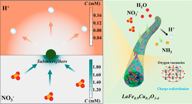
The surface potential will be changed by B-site substitution in the perovskite structure.35,36 Therefore, Kelvin probe force microscopy (KPFM) was conducted to investigate the surface potential of the LF and LF0.9Cu0.1 submicrofibers. The potential distributions at the LF0.9Cu0.1 and LF submicrofiber surfaces are shown in Figure 4a,b with their corresponding topography images. A rectangular region (along the direction of the arrow) was chosen to quantify the surface potential variation. As shown in Figure 4c, the surface potential of LF0.9Cu0.1 is roughly 66 mV higher than that of LF. The above results show that the work function of LF0.9Cu0.1 is about 0.066 eV lower than that of LF according to the conversion formula between the work function and surface potential.36 A lower work function of LF0.9Cu0.1 submicrofibers implies a smaller energy barrier for electron transfer to the reactant (NO3–).54 Notably, the surface potential of LF0.9Cu0.1 submicrofibers becomes more positive, which indicates that LF0.9Cu0.1 is more favorable to adsorbing and enriching NO3–. Therefore, it is advantageous by constructing eNITRR catalysts with more positive surface potential in addressing the issue of low activity resulting from weak mass transfer and small concentration gradients near the electrode region in low-concentration NO3– electrolytes.55 Meanwhile, COMSOL Multiphysics simulations were used to simulate the ionic distribution after the variation of the potential on the nanoreactor surface. Since the competitive HER can inhibit the eNITRR process, the concentration of hydrogen ions on the catalyst surface is also an important factor affecting the eNITRR performance. The variations of ion concentrations are described through the Nernst–Planck equation (see the details in the Supporting Information). Before the simulation, it is assumed that the anions and cations are distributed randomly, without electrostatic force. After the surface potential becomes more positive, the distributions of the NO3– and H+ ions are shown in Figures 4d,e and S24. The NO3– concentration increases gradually, indicating a NO3– enrichment. On the contrary, the H+ concentration at the surface of LF0.9Cu0.1 submicrofibers decreases progressively. These results demonstrate that a surface with more positive potential would be beneficial for not only promoting the enrichment of NO3– ions but also reducing the HER process (Figure 4f).
Figure 4.

Surface potential distribution of (a) LF0.9Cu0.1 and (b) LF submicrofibers. (c) Surface potential values extracted in (a,b). Top view of the model of the variation of (d) NO3– and (e) H+ concentrations on the fiber surface. (f) Schematic illustration of the ion movement on the catalyst surface with more positive potential.
The mechanism for the eNITRR process was experimentally probed by two-dimensional operando FT-IR spectroscopy and online DEMS. The infrared signals are collected from 1100 to 2200 cm–1 during a negative scan from −0.8 to −1.2 V vs RHE (Figure 5a). It can be concluded that as the potentials become more negative, the intensity of the characteristic peaks increases. This demonstrates the emergence of the rocking mode of –NH2 at 1190 cm–1,56 the wagging mode of –NH2 at 1307 cm–1,57 and M–N–O groups in the range of 1800–2000 cm–1.58 Moreover, the molecular intermediates and products were detected by online DEMS with an applied voltage between −0.6 and −1.2 V vs RHE (Figure 5b). The m/z signals of 46, 30, and 17 appear during seven subsequent cycles and correspond to the NO2, NO, and NH3 species, respectively.
Figure 5.

(a) Two-dimensional operando FT-IR spectra of LF0.9Cu0.1. Here, the pink represents high values of transmittance, while the green represents low values of transmittance. (b) DEMS signals of gaseous intermediates/products during seven cycles. (c) Charge density difference of LF0.9Cu0.1 coupled with NO3-. (d) Gibbs free energy diagrams of the eNITRR on the surface of LF and LF0.9Cu0.1.
DFT calculations were also conducted to explore the relationship between the Cu substitution and improved eNITRR activity. The charge density difference of LF0.9Cu0.1 after adsorbing NO3– is plotted in Figure 5c, which shows a charge transfer from Fe to adsorbed NO3– and provides clues into the adsorption and activation of NO3– for subsequent hydrogenation. Based on the findings from DEMS/FT-IR spectroscopy measurements, the reaction pathway of NO3– electroreduction could be deduced, and the free energy of every intermediate over LF and LF0.9Cu0.1 was calculated. According to a previous study,38,59 the eNITRR process can be considered as a hydrogenation process (Figure S25). Before the calculation of the total reaction steps, it is crucial to determine the mode of NO3– adsorption and hydrogenation on the LF0.9Cu0.1 surface. The free energies of two different pathways to form *NO3 and *HNO3 were calculated. As shown in Figure 5d, the free energy values of the NO3– coupling and first proton–electron coupling steps of single oxygen (O1 mode) on the Fe site are lower than those of dioxygen (O2 mode). For example, the free energy values for the first proton–electron coupling step (*NO3 + H+ + e– → *HNO3) with the O1 and O2 modes are 1.83 and 2.67 eV, respectively, which indicate that the O1 mode is a more optimal structure for the coupling step between the LF0.9Cu0.1 catalyst and NO3– species, as well as the following hydrogenation. It is noted that the byproduct NO2(g) can be produced in the side reaction *HNO3 + H+ + e– → *OH + NO2(g). The free energy of this potential intermediate was also calculated with a larger free energy of −2.61 eV than that of the step for the generation of the *NO2 species (−3.86 eV). Therefore, the side reaction is much less likely to occur than the second proton–electron coupling step (*HNO3 + H+ + e– → H2O + *NO2). After other possibilities are excluded, the total reaction pathway is shown as follows. First, the reactant NO3– is chemically absorbed on the catalyst surface to form *NO3 with a decrease of total energy, indicating the driving force of this reaction step. Then, the N–O bond is continuously cleaved by proton-coupled electron transfer to form *NO2 and *NO. During the following hydrogenation processes, the *NO intermediate is converted to *HNO, *H2NO, and *O species gradually. In the final active site refreshing process, the *O intermediate is coupled with two other protons and converted to a H2O molecule. To be noted, different intermediates were adsorbed on the surface of catalysts, and the most stable adsorption models are employed to describe the eNITRR process (illustrations of Figure 5d). For both LF0.9Cu0.1 and LF surfaces, nonspontaneous reaction steps can be clearly observed that will influence the reaction rate of the eNITRR process. Among these nonspontaneous steps, the RDS is the first proton–electron coupling step (*NO3 + H+ + e– → *HNO3), where the energy barriers are 2.07 and 1.83 eV for LF and LF0.9Cu0.1, respectively. This indicates that the eNITRR process can be facilitated on the surface of LF0.9Cu0.1. Combining all experimental results with the theoretical calculations, it can be concluded that the eNITRR performance can be promoted by the B-site substitution strategy.
3. Conclusions
In summary, we have demonstrated that perovskite LF0.9Cu0.1 submicrofibers can act as a selective and efficient electrocatalyst to reduce NO3– to valuable NH3. At the optimal potential of −0.9 V, the NH3 yield rate, FE, and selectivity can reach 349 ± 15 μg h–1 mg–1cat., 48 ± 2%, and 88 ± 4%, respectively. Synchrotron-based XAS revealed the charge redistribution on the L0.9Cu0.1 submicrofiber and confirmed the increase of hybridization of the Fe 3d–O 2p orbital, which favors the generation of surface OVs. Combined with the results of KPFM and COMSOL Multiphysics simulations, it is shown that a more positive surface can be induced by the cation substitution strategy, which promotes the fixation of more NO3– anions on the catalyst surface. Based on a variety of in situ characterizations and DFT calculations, the reaction pathway was deduced. The results showed that the lower free energy for the RDS (*NO3 + H+ + e– → *HNO3) for LF0.9Cu0.1 led to its optimal NH3 synthesis performance. This work opens new avenues for designing efficient perovskite-type electrocatalytic NH3 synthesis catalysts via a cation substitution strategy.
Acknowledgments
We are grateful for the financial support from the National Natural Science Foundation of China (52161135302, 52211530489, and 22075042) and the Research Foundation Flanders (1298323N). We gratefully acknowledge access to the BL14W1 beamline of the Shanghai Synchrotron Radiation Facility (SSRF). J.H. and M.B.J.R. gratefully acknowledge the financial support from the Research Foundation Flanders (FWO, grant nos. G0983.19N, G0F2322N, and VS06523N) and Interne Fondsen KU Leuven through project (C3/20/067 and CELSA/21/016). J.H. acknowledges the Flemish government for long-term structural funding Methusalem (CASAS2, Meth/15/04) and for the Moonshot cSBO project P2C (HBC.2019.0108) and the MPI as an MPI fellow. We also thank characterization supported by the Central Laboratory, School of Chemical and Material Engineering, Jiangnan University.
Supporting Information Available
The Supporting Information is available free of charge at https://pubs.acs.org/doi/10.1021/jacs.3c06402.
Detailed experimental procedures, supported physical and electrochemical characterization of materials by SEM, TEM, XRD, 1H nuclear magnetic resonance, XPS, cyclic voltammetry, EPR, ICP-MS, and additional EXAFS results (PDF)
Open access funded by Max Planck Society.
The authors declare no competing financial interest.
Supplementary Material
References
- Suryanto B. H. R.; Du H.-L.; Wang D.; Chen J.; Simonov A. N.; MacFarlane D. R. Challenges and prospects in the catalysis of electroreduction of nitrogen to ammonia. Nat. Catal. 2019, 2, 290–296. 10.1038/s41929-019-0252-4. [DOI] [Google Scholar]
- Suryanto B. H. R.; Matuszek K.; Choi J.; Hodgetts R. Y.; Du H.-L.; Bakker J. M.; Kang C. S. M.; Cherepanov P. V.; Simonov A. N.; MacFarlane D. R. Nitrogen reduction to ammonia at high efficiency and rates based on a phosphonium proton shuttle. Science 2021, 372, 1187–1191. 10.1126/science.abg2371. [DOI] [PubMed] [Google Scholar]
- Soloveichik G. Electrochemical synthesis of ammonia as a potential alternative to the Haber-Bosch process. Nat. Catal. 2019, 2, 377–380. 10.1038/s41929-019-0280-0. [DOI] [Google Scholar]
- Guo W.; Zhang K.; Liang Z.; Zou R.; Xu Q. Electrochemical nitrogen fixation and utilization: theories, advanced catalyst materials and system design. Chem. Soc. Rev. 2019, 48, 5658–5716. 10.1039/C9CS00159J. [DOI] [PubMed] [Google Scholar]
- Tang C.; Qiao S.-Z. How to explore ambient electrocatalytic nitrogen reduction reliably and insightfully. Chem. Soc. Rev. 2019, 48, 3166–3180. 10.1039/C9CS00280D. [DOI] [PubMed] [Google Scholar]
- Jin H.; Li L.; Liu X.; Tang C.; Xu W.; Chen S.; Song L.; Zheng Y.; Qiao S.-Z. Nitrogen vacancies on 2D layered W2N3: A stable and efficient active site for nitrogen reduction reaction. Adv. Mater. 2019, 31, 1902709. 10.1002/adma.201902709. [DOI] [PubMed] [Google Scholar]
- Singstock N. R.; Musgrave C. B. How the bioinspired Fe2Mo6S8 Chevrel breaks electrocatalytic nitrogen reduction scaling relations. J. Am. Chem. Soc. 2022, 144, 12800–12806. 10.1021/jacs.2c03661. [DOI] [PubMed] [Google Scholar]
- Jiao S.; Fu X.; Ruan S.; Zeng Y.-J.; Huang H. Breaking the periodic arrangement of atoms for the enhanced electrochemical reduction of nitrogen and water oxidation. Sci. China Mater. 2022, 65, 147–154. 10.1007/s40843-021-1729-2. [DOI] [Google Scholar]
- Qing G.; Ghazfar R.; Jackowski S. T.; Habibzadeh F.; Ashtiani M. M.; Chen C.-P.; Smith M. R. III; Hamann T. W. Recent advances and challenges of electrocatalytic N2 reduction to ammonia. Chem. Rev. 2020, 120, 5437–5516. 10.1021/acs.chemrev.9b00659. [DOI] [PubMed] [Google Scholar]
- Wang C.; Wang Q.-C.; Wang K.-X.; De Ras M.; Chu K.; Gu L.-L.; Lai F.; Qiu S.-Y.; Guo H.; Zuo P.-J.; Hofkens J.; Zhu X.-D. Bimetallic NiCo boride nanoparticles confined in a MXene network enable efficient ambient ammonia electrosynthesis. J. Energy Chem. 2023, 77, 469–478. 10.1016/j.jechem.2022.11.010. [DOI] [Google Scholar]
- Wang J.; Yu L.; Hu L.; Chen G.; Xin H.; Feng X. Ambient ammonia synthesis via palladium-catalyzed electrohydrogenation of dinitrogen at low overpotential. Nat. Commun. 2018, 9, 1795. 10.1038/s41467-018-04213-9. [DOI] [PMC free article] [PubMed] [Google Scholar]
- Chu K.; Ras M. D.; Rao D.; Martens J. A.; Hofkens J.; Lai F.; Liu T. Tailoring the d-band center of double-perovskite LaCoxNi1-xO3 nanorods for high activity in artificial N2 fixation. ACS Appl. Mater. Interfaces 2021, 13, 13347–13353. 10.1021/acsami.1c01510. [DOI] [PubMed] [Google Scholar]
- Zong W.; Gao H.; Ouyang Y.; Chu K.; Guo H.; Zhang L.; Zhang W.; Chen R.; Dai Y.; Guo F.; Zhu J.; Zhang Z.; Ye C.; Miao Y.-E.; Hofkens J.; Lai F.; Liu T. Bio-inspired aerobic-hydrophobic Janus interface on partially carbonized iron heterostructure promotes bifunctional nitrogen fixation. Angew. Chem., Int. Ed. 2023, 62, e202218122 10.1002/anie.202218122. [DOI] [PubMed] [Google Scholar]
- Wang Y.; Xu A.; Wang Z.; Huang L.; Li J.; Li F.; Wicks J.; Luo M.; Nam D.-H.; Tan C.-S.; Ding Y.; Wu J.; Lum Y.; Dinh C.-T.; Sinton D.; Zheng G.; Sargent E. H. Enhanced nitrate-to-ammonia activity on copper-nickel alloys via tuning of intermediate adsorption. J. Am. Chem. Soc. 2020, 142, 5702–5708. 10.1021/jacs.9b13347. [DOI] [PubMed] [Google Scholar]
- Guo Y.; Zhang R.; Zhang S.; Zhao Y.; Yang Q.; Huang Z.; Dong B.; Zhi C. Pd doping-weakened intermediate adsorption to promote electrocatalytic nitrate reduction on TiO2 nanoarrays for ammonia production and energy supply with zinc-nitrate batteries. Energy Environ. Sci. 2021, 14, 3938–3944. 10.1039/D1EE00806D. [DOI] [Google Scholar]
- Su L.; Han D.; Zhu G.; Xu H.; Luo W.; Wang L.; Jiang W.; Dong A.; Yang J. Tailoring the assembly of iron nanoparticles in carbon microspheres toward high-performance electrocatalytic denitrification. Nano Lett. 2019, 19, 5423–5430. 10.1021/acs.nanolett.9b01925. [DOI] [PubMed] [Google Scholar]
- Bhatnagar A.; Sillanpää M. A review of emerging adsorbents for nitrate removal from water. Chem. Eng. J. 2011, 168, 493–504. 10.1016/j.cej.2011.01.103. [DOI] [Google Scholar]
- Yang Y.-Y.; Toor G. S. Sources and mechanisms of nitrate and orthophosphate transport in urban stormwater runoff from residential catchments. Water Res. 2017, 112, 176–184. 10.1016/j.watres.2017.01.039. [DOI] [PubMed] [Google Scholar]
- Duca M.; Koper M. T. M. Powering denitrification: the perspectives of electrocatalytic nitrate reduction. Energy Environ. Sci. 2012, 5, 9726–9742. 10.1039/c2ee23062c. [DOI] [Google Scholar]
- Bu Y.; Wang C.; Zhang W.; Yang X.; Ding J.; Gao G. Electrical pulse-driven periodic self-repair of Cu-Ni tandem catalyst for efficient ammonia synthesis from nitrate. Angew. Chem., Int. Ed. 2023, 62, e202217337 10.1002/anie.202217337. [DOI] [PubMed] [Google Scholar]
- Wang Y.; Zhou W.; Jia R.; Yu Y.; Zhang B. Unveiling the activity origin of a copper-based electrocatalyst for selective nitrate reduction to ammonia. Angew. Chem., Int. Ed. 2020, 59, 5350–5354. 10.1002/anie.201915992. [DOI] [PubMed] [Google Scholar]
- Yang J.; Qi H.; Li A.; Liu X.; Yang X.; Zhang S.; Zhao Q.; Jiang Q.; Su Y.; Zhang L.; Li J.-F.; Tian Z.-Q.; Liu W.; Wang A.; Zhang T. Potential-driven restructuring of Cu single atoms to nanoparticles for boosting the electrochemical reduction of nitrate to ammonia. J. Am. Chem. Soc. 2022, 144, 12062–12071. 10.1021/jacs.2c02262. [DOI] [PubMed] [Google Scholar]
- Chen F.-Y.; Wu Z.-Y.; Gupta S.; Rivera D. J.; Lambeets S. V.; Pecaut S.; Kim J. Y. T.; Zhu P.; Finfrock Y. Z.; Meira D. M.; King G.; Gao G.; Xu W.; Cullen D. A.; Zhou H.; Han Y.; Perea D. E.; Muhich C. L.; Wang H. Efficient conversion of low-concentration nitrate sources into ammonia on a Ru-dispersed Cu nanowire electrocatalyst. Nat. Nanotechnol. 2022, 17, 759–767. 10.1038/s41565-022-01121-4. [DOI] [PubMed] [Google Scholar]
- Liu H.; Lang X.; Zhu C.; Timoshenko J.; Rüscher M.; Bai L.; Guijarro N.; Yin H.; Peng Y.; Li J.; Liu Z.; Wang W.; Cuenya B. R.; Luo J. Efficient electrochemical nitrate reduction to ammonia with copper-supported Rhodium cluster and single-atom catalysts. Angew. Chem., Int. Ed. 2022, 61, e202202556 10.1002/anie.202202556. [DOI] [PubMed] [Google Scholar]
- Yang W.-J.; Yang L.-H.; Peng H.-J.; Lv S.-H.; Muhammad Adeel Sharif H.; Sun W.; Li W.; Yang C.; Lin H. Perovskite oxide LaMO3-δ (M = Fe, Co, Ni and Cu) cathode for efficient electroreduction of nitrate. Sep. Purif. Technol. 2022, 295, 121278. 10.1016/j.seppur.2022.121278. [DOI] [Google Scholar]
- Wang J.; Wu D.; Li M.; Wei X.; Yang X.; Shao M.; Gu M. Bismuth ferrite as an electrocatalyst for the electrochemical nitrate reduction. Nano Lett. 2022, 22, 5600–5606. 10.1021/acs.nanolett.2c02026. [DOI] [PubMed] [Google Scholar]
- Gong Z.; Zhong W.; He Z.; Jia C.; Zhou D.; Zhang N.; Kang X.; Chen Y. Improving electrochemical nitrate reduction activity of layered perovskite oxide La2CuO4 via B-site doping. Catal. Today 2022, 402, 259–265. 10.1016/j.cattod.2022.04.019. [DOI] [Google Scholar]
- Zhang H.; Xu Y.; Lu M.; Xie X.; Huang L. Perovskite oxides for cathodic electrocatalysis of energy-related gases: from O2 to CO2 and N2. Adv. Funct. Mater. 2021, 31, 2101872. 10.1002/adfm.202101872. [DOI] [Google Scholar]
- Wang H.; Wang J.; Pi Y.; Shao Q.; Tan Y.; Huang X. Double perovskite LaFexNi1-xO3 nanorods enable efficient oxygen evolution electrocatalysis. Angew. Chem., Int. Ed. 2019, 58, 2316–2320. 10.1002/anie.201812545. [DOI] [PubMed] [Google Scholar]
- Zhu Y.; Zhou W.; Zhong Y.; Bu Y.; Chen X.; Zhong Q.; Liu M.; Shao Z. A perovskite nanorod as bifunctional electrocatalyst for overall water splitting. Adv. Energy Mater. 2017, 7, 1602122. 10.1002/aenm.201602122. [DOI] [Google Scholar]
- You H.; Wu Z.; Zhang L.; Ying Y.; Liu Y.; Fei L.; Chen X.; Jia Y.; Wang Y.; Wang F.; Ju S.; Qiao J.; Lam C.-H.; Huang H. Harvesting the vibration energy of BiFeO3 nanosheets for hydrogen evolution. Angew. Chem., Int. Ed. 2019, 58, 11779–11784. 10.1002/anie.201906181. [DOI] [PubMed] [Google Scholar]
- Qin L.; Liu Y.; Zhu S.; Wu D.; Wang G.; Zhang J.; Wang Y.; Hou L.; Yuan C. Formation and operating mechanisms of single-crystalline perovskite NaNbO3 nanocubes/few-layered Nb2CTx MXene hybrids towards Li-ion capacitors. J. Mater. Chem. A 2021, 9, 20405–20416. 10.1039/D1TA03684J. [DOI] [Google Scholar]
- Guan D.; Zhou J.; Huang Y.-C.; Dong C.-L.; Wang J.-Q.; Zhou W.; Shao Z. Screening highly active perovskites for hydrogen-evolving reaction via unifying ionic electronegativity descriptor. Nat. Commun. 2019, 10, 3755. 10.1038/s41467-019-11847-w. [DOI] [PMC free article] [PubMed] [Google Scholar]
- Hwang J.; Rao R. R.; Giordano L.; Katayama Y.; Yu Y.; Shao-Horn Y. Perovskites in catalysis and electrocatalysis. Science 2017, 358, 751–756. 10.1126/science.aam7092. [DOI] [PubMed] [Google Scholar]
- Jacobs R.; Booske J.; Morgan D. Understanding and controlling the work function of perovskite oxides using density functional theory. Adv. Funct. Mater. 2016, 26, 5471–5482. 10.1002/adfm.201600243. [DOI] [Google Scholar]
- Tong X.; Zhao Y.; Zhuo Z.; Yang Z.; Wang S.; Liu Y.; Lu N.; Li H.; Zhai T. Dual-regulation of defect sites and vertical conduction by spiral domain for electrocatalytic hydrogen evolution. Angew. Chem., Int. Ed. 2022, 61, e202112953 10.1002/anie.202112953. [DOI] [PubMed] [Google Scholar]
- She S.; Zhu Y.; Wu X.; Hu Z.; Shelke A.; Pong W.-F.; Chen Y.; Song Y.; Liang M.; Chen C.-T.; Wang H.; Zhou W.; Shao Z. Realizing high and stable electrocatalytic oxygen evolution for iron-based perovskites by Co-doping-induced structural and electronic modulation. Adv. Funct. Mater. 2022, 32, 2111091. 10.1002/adfm.202111091. [DOI] [Google Scholar]
- Jia R.; Wang Y.; Wang C.; Ling Y.; Yu Y.; Zhang B. Boosting selective nitrate electroreduction to ammonium by constructing oxygen vacancies in TiO2. ACS Catal. 2020, 10, 3533–3540. 10.1021/acscatal.9b05260. [DOI] [Google Scholar]
- Zhu D.; Zhang L.; Ruther R. E.; Hamers R. J. Photo-illuminated diamond as a solid-state source of solvated electrons in water for nitrogen reduction. Nat. Mater. 2013, 12, 836–841. 10.1038/nmat3696. [DOI] [PubMed] [Google Scholar]
- Chu K.; Qin J.; Zhu H.; De Ras M.; Wang C.; Xiong L.; Zhang L.; Zhang N.; Martens J. A.; Hofkens J.; Lai F.; Liu T. High-entropy perovskite oxides: A versatile class of materials for nitrogen reduction reactions. Sci. China Mater. 2022, 65, 2711–2720. 10.1007/s40843-022-2021-y. [DOI] [Google Scholar]
- Tian X.; Zheng C.; Zhao H. Ce-modified SrFeO3-δ for ethane oxidative dehydrogenation coupled with CO2 splitting via a chemical looping scheme. Appl. Catal., B 2022, 303, 120894. 10.1016/j.apcatb.2021.120894. [DOI] [Google Scholar]
- Tang X.; Wu Y.; Zhai W.; Chu T.; Li L.; Huang B.; Hu T.; Yuan K.; Chen Y. Iron-based nanocomposites implanting in N, P Co-doped carbon nanosheets as efficient oxygen reduction electrocatalysts for Zn-air batteries. Compos. Commun. 2022, 29, 100994. 10.1016/j.coco.2021.100994. [DOI] [Google Scholar]
- Barbero B. P.; Gamboa J. A.; Cadús L. E. Synthesis and characterisation of La1-xCaxFeO3 perovskite-type oxide catalysts for total oxidation of volatile organic compounds. Appl. Catal., B 2006, 65, 21–30. 10.1016/j.apcatb.2005.11.018. [DOI] [Google Scholar]
- Dai J.; Zhu Y.; Yin Y.; Tahini H. A.; Guan D.; Dong F.; Lu Q.; Smith S. C.; Zhang X.; Wang H.; Zhou W.; Shao Z. Super-exchange interaction induced overall optimization in ferromagnetic perovskite oxides enables ultrafast water oxidation. Small 2019, 15, 1903120. 10.1002/smll.201903120. [DOI] [PubMed] [Google Scholar]
- Wang Y.; Zhang L.; Niu Y.; Fang D.; Wang J.; Su Q.; Wang C. Boosting NH3 production from nitrate electroreduction via electronic structure engineering of Fe3C nanoflakes. Green Chem. 2021, 23, 7594–7608. 10.1039/D1GC01913A. [DOI] [Google Scholar]
- Zhang L.; Cong M.; Ding X.; Jin Y.; Xu F.; Wang Y.; Chen L.; Zhang L. A Janus Fe-SnO2 catalyst that enables bifunctional electrochemical nitrogen fixation. Angew. Chem., Int. Ed. 2020, 59, 10888–10893. 10.1002/anie.202003518. [DOI] [PubMed] [Google Scholar]
- Cong Y.; Geng Z.; Zhu Q.; Hou H.; Wu X.; Wang X.; Huang K.; Feng S. Cation-exchange-induced metal and alloy dual-exsolution in perovskite ferrite oxides boosting the performance of Li-O2 battery. Angew. Chem., Int. Ed. 2021, 60, 23380–23387. 10.1002/anie.202110116. [DOI] [PubMed] [Google Scholar]
- Xi X.; Liu J.; Luo W.; Fan Y.; Zhang J.; Luo J.-L.; Fu X.-Z. Unraveling the enhanced kinetics of Sr2Fe1+xMo1-xO6-δ electrocatalysts for high-performance solid oxide cells. Adv. Energy Mater. 2021, 11, 2102845. 10.1002/aenm.202102845. [DOI] [Google Scholar]
- Liu X.; Mi J.; Shi L.; Liu H.; Liu J.; Ding Y.; Shi J.; He M.; Wang Z.; Xiong S.; Zhang Q.; Liu Y.; Wu Z.; Chen J.; Li J. In situ modulation of A-site vacancies in LaMnO3.15 perovskite for surface lattice oxygen activation and boosted redox reactions. Angew. Chem., Int. Ed. 2021, 60, 26747–26754. 10.1002/anie.202111610. [DOI] [PubMed] [Google Scholar]
- Dai J.; Zhu Y.; Tahini H. A.; Lin Q.; Chen Y.; Guan D.; Zhou C.; Hu Z.; Lin H.-J.; Chan T.-S.; Chen C.-T.; Smith S. C.; Wang H.; Zhou W.; Shao Z. Single-phase perovskite oxide with super-exchange induced atomic-scale synergistic active centers enables ultrafast hydrogen evolution. Nat. Commun. 2020, 11, 5657. 10.1038/s41467-020-19433-1. [DOI] [PMC free article] [PubMed] [Google Scholar]
- Zhu Y.; Zhou W.; Yu J.; Chen Y.; Liu M.; Shao Z. Enhancing electrocatalytic activity of perovskite oxides by tuning cation deficiency for oxygen reduction and evolution reactions. Chem. Mater. 2016, 28, 1691–1697. 10.1021/acs.chemmater.5b04457. [DOI] [Google Scholar]
- Xu M.; Xu F.; Zhu K.; Xu X.; Deng P.; Wu W.; Ye W.; Sun Z.; Gao P. Atomic layer deposition technique refining oxygen vacancies in TiO2 passivation layer for photoelectrochemical ammonia synthesis. Compos. Commun. 2022, 29, 101037. 10.1016/j.coco.2021.101037. [DOI] [Google Scholar]
- Zhu T.; Chen Q.; Liao P.; Duan W.; Liang S.; Yan Z.; Feng C. Single-atom Cu catalysts for enhanced electrocatalytic nitrate reduction with significant alleviation of nitrite production. Small 2020, 16, 2004526. 10.1002/smll.202004526. [DOI] [PubMed] [Google Scholar]
- Cheon J. Y.; Kim J. H.; Kim J. H.; Goddeti K. C.; Park J. Y.; Joo S. H. Intrinsic relationship between enhanced oxygen reduction reaction activity and nanoscale work function of doped carbons. J. Am. Chem. Soc. 2014, 136, 8875–8878. 10.1021/ja503557x. [DOI] [PubMed] [Google Scholar]
- Sun W.-J.; Ji H.-Q.; Li L.-X.; Zhang H.-Y.; Wang Z.-K.; He J.-H.; Lu J.-M. Built-in electric field triggered interfacial accumulation effect for efficient nitrate removal at ultra-low concentration and electroreduction to ammonia. Angew. Chem., Int. Ed. 2021, 60, 22933–22939. 10.1002/anie.202109785. [DOI] [PubMed] [Google Scholar]
- Wang Y.; Wang C.; Li M.; Yu Y.; Zhang B. Nitrate electroreduction: mechanism insight, in situ characterization, performance evaluation, and challenges. Chem. Soc. Rev. 2021, 50, 6720–6733. 10.1039/D1CS00116G. [DOI] [PubMed] [Google Scholar]
- Lv C.; Zhong L.; Liu H.; Fang Z.; Yan C.; Chen M.; Kong Y.; Lee C.; Liu D.; Li S.; Liu J.; Song L.; Chen G.; Yan Q.; Yu G. Selective electrocatalytic synthesis of urea with nitrate and carbon dioxide. Nat. Sustain. 2021, 4, 868–876. 10.1038/s41893-021-00741-3. [DOI] [Google Scholar]
- Hadjiivanov K.; Knözinger H. Species formed after NO adsorption and NO + O2 co-adsorption on TiO2: an FTIR spectroscopic study. Phys. Chem. Chem. Phys. 2000, 2, 2803–2806. 10.1039/b002065f. [DOI] [Google Scholar]
- Ye S.; Chen Z.; Zhang G.; Chen W.; Peng C.; Yang X.; Zheng L.; Li Y.; Ren X.; Cao H.; Xue D.; Qiu J.; Zhang Q.; Liu J. Elucidating the activity, mechanism and application of selective electrosynthesis of ammonia from nitrate on cobalt phosphide. Energy Environ. Sci. 2022, 15, 760–770. 10.1039/D1EE03097C. [DOI] [Google Scholar]
Associated Data
This section collects any data citations, data availability statements, or supplementary materials included in this article.