Abstract
Introduction:
Minimally invasive image-guided interventions have changed the face of procedural medicine. For these procedures, safety and efficacy depend on precise needle placement. Needle targeting devices help improve the accuracy of needle placement, but their use has not seen broad penetration. Some of these devices are costly and require major modifications to the clinical workflow. In this paper, we developed a low-cost, disposable, and easy-to-use angulation tracking device, which was based on a redesigned commercial passive needle holder.
Material and methods:
The new design provided real-time angulation information for needle tracking. In this design, two potentiometers were used as angulation sensors, and they were connected to two axes of the passive needle holder’s arch structure through a 3D-printed bridge structure. A control unit included an Arduino Pro Mini, a Bluetooth module, and two rechargeable batteries. The angulation was calculated and communicated in real time to a novel developed smartphone app, where real-time angulation information was displayed for guiding the operator to position the needle to the planned angles.
Results:
The open-air test results showed that the average errors are 1.03° and 1.08° for left-right angulation and head-foot angulation, respectively. The animal cadaver tests revealed that the novel system had an average angular error of 3.2° and a radial distance error of 3.1 mm.
Conclusion:
The accuracy was comparable with some commercially available solutions. The novel and low-cost needle tracking device may find a role as part of a real-time precision approach to both planning and implementation of image-guided therapies.
Keywords: Angulation, Smartphone, Needle Placement, Image-guided therapy, Medical device
Introduction
Image modalities, such as ultrasound (US), magnetic resonance imaging (MRI), and computed tomography (CT), are commonly used to guide needle instruments during interventions (1–3). The accuracy of the needle placement is associated with efficacy, risk, and outcomes for certain needle-based procedures (1–6). Misdiagnosis, complications, and delayed or unsuccessful treatment can result from even slight needle misplacement (1, 6). To improve the accuracy of needle placement, assist devices that combine tracking and navigation capabilities have been developed. Multiple hardware and software assist-systems provide angulation or semi-automation for needle-based procedures, including handheld disposable devices, T-integrated robotics systems, or electromagnetic or optical-based navigation and treatment planning systems (7,8). An example is a CT-compatible robotic system, presented by Shahriari, guides and inserts a needle for lung biopsy of nodules > 5 mm (7). Commercial original equipment manufacturer (OEM) technologies are also available for image-guided procedures, such as the Cascination-One system (Cascination AG, Bern, Switzerland), reporting an accuracy of 2.9 ± 2.3 mm for needle microwave ablation (8). However, most of these systems are relatively costly, non-ergonomic, and require bulky equipment setup or calibration in a dedicated imaging suite. Less technologically advanced navigation may be assisted by some small size handheld disposable guiding device also available in the market.
A semi-orthogonal dual-arc needle stabilization guidance device (SeeStar®, AprioMed, Uppsala, Sweden) is an FDA 510k-cleared external localization device for assisting needle stabilization and insertion. The device can be used for X-ray, CT, cone beam computed tomography (CBCT), or ultrasound-guided procedures. The device includes a plastic adhesive propeller-shaped base, two movable semi-circular plastic bridges, a central metallic needle guide (in 14-G, 17-G, and 20-G sizes), and a plastic hub which secures and grips the needle when fastened. This guiding device has the ability to guide the needle with a rotation of 360° and an angulation of 120° (9, 10). During the rotation and angulation, the blunt tip of the central metallic needle guide rotates about the skin entry point, and is thus kept in the same skin location percutaneously. This ensures that the needle is always inserted into the same point in the skin, as a remote center of motion (RCM) device (8–10).
The passive needle holder on the SeeStar® guiding device has the ability to hold and stabilize a needle during imaging as well. The metallic needle guide can be used for the localization of needle trajectory, with a linear footprint and distal artifact on CT. Roberts et al. (10) used the SeeStar® guiding device with a musculoskeletal phantom and concluded that the device was useful for planning a biopsy approach for deep lesions or lesions near critical structures. Kroes et al. (11) used the device on an abdominal phantom to successfully hit predetermined targets. Paolucci et al. (12) used the device to guide an ablation needle to liver tumors with ultrasound imaging. However, a major pitfall of such a “step-and-shoot” device is the inability to track and display the real-time angulation to the operator, which precludes exact iterative planning, or implementation of a predetermined plan with feedback precision. This may increase the needle insertion time and radiation dose since repeated imaging procedures are needed to verify the needle position (13). In addition, this “step-and-shoot” technique requires the patient to be moved in and out of the CT scanner for needle adjustment, decreasing the workflow efficiency. Therefore, in this study, we present a needle angular tracker and stabilizer custom-fabricated and integrated with this commercial passive needle holder (Seestar® guiding device). Combined with the developed smartphone app, the needle guide allows real-time angulation to be displayed to the operator for navigating the needle insertion procedure (Figure 1 (a)). The proposed clinical workflow as shown below:
Figure 1.
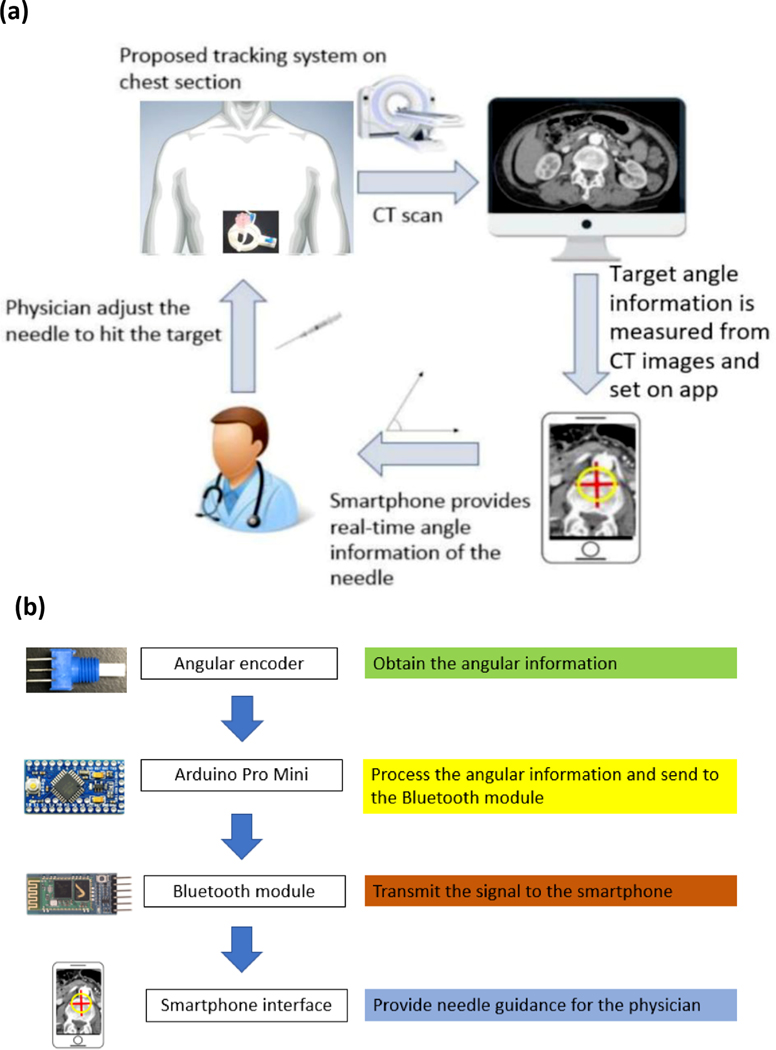
(a) System overview of the needle angular tracker. (b) Integrated system data flow from the needle angular tracker terminal to the smartphone terminal.
Step 1: Patient is set up in the scanner, and the target area is sterilized and then covered with a radiopaque grid sheet.
Step 2: CT scan is taken, and then the skin entry point is selected based on the radiopaque grid. Next, the path planning is planned.
Step 3: Smartphone application is turned on, with manual or semi-automatic input of the target angulation and path plan information.
Step 4: Device is placed directly onto the patient’s skin in the target area.
Step 5: The device is aligned with the scanner laser.
Step 6: Needle adjustment is initiated using the angular information provided by the smartphone app.
Step 7: Confirmatory CT for needle position is taken prior to final biopsy or ablation.
Step 8: For composite ablations, or multifocal procedures, needle adjustment can be made after iterative feedback or integration with treatment planning software.
Material and methods
Tracking system design
The whole system contained five sections: two calibrated angular sensors, a microcontroller, a communication unit, a power unit, and a display. Two calibrated 3310Y series 10 kiloohm potentiometers (Bourns Inc., Riverside, CA, USA) were used as angulation sensors. They were connected with two axes of the passive needle holder’s arch structure for measuring the rotation angle of the axes. An Arduino Pro Mini 328 (SparkFun Electronics, Boulder, CO, USA) was used for data processing and communicating with other devices. An HC-05 Bluetooth module was used as a communication unit to exchange information with a smartphone. Two rechargeable 400 mAh 3.5 V lithium batteries were used as power sources. All of these components were enclosed in a black box, and together they functioned as the control unit. The fully charged batteries could provide power for three hours. A smart phone (Android OS) was used to set the target angles and display the real-time measured angles, to guide the operator.
The potentiometer was connected as shown in Figure 2. The angle was calculated in the microcontroller based on equation (1), where was the total angle that the potentiometer could rotate, is the measured voltage, is the total voltage that applied in the potentiometer.
Figure 2.

Illustration of potentiometer connection. (1) The power input (VCC), which is 5 V, (2) the analogue signal input (AI), (3) the ground connection (GND).
| (1) |
The angle data calculated from the two potentiometers was encoded into one array for improving data communication efficiency and true integration between the control unit and smartphone app.
The measurement algorithm was programmed into the Arduino Pro Mini 328. It sets the first data as the initial point (0°) after receiving the “start” signal from the smartphone app. This is the calibration step. The difference between the measured data and the initial point is calculated, encoded, and then wirelessly sent to the smartphone app through the Bluetooth module. The smartphone app, which was developed in APP Inventor® (MIT, Cambridge, MA, USA), can be used to set up the target angulation and display the real-time measured angulation in numerical format. In addition, the target angulation, which is displayed as a red cross, and the real-time angulation, which is displayed as a red circle, are drawn in a Cartesian coordinate system where the target angulation is the origin. Furthermore, when the measured angulation is close to the target angulation, the app can generate an audible beeping sound to alert the operator as to proximity to target angle. The system flowchart is shown in Figure 1(b).
Needle angular tracker base
In this study, only the arch structure of SeeStar® was retained for the purpose of holding the needle. The base part was significantly modified and integrated with disposable angular encoders. The needle holder is shown in different views in Figure 3 (a-c). The base has two slots in two axes for housing potentiometers, and a hollow cylinder structure is used as a bridge to connect the shafts of the potentiometers with the arch structure. The shaft and arch structure are coaxial. On the back of the base, a ring-shaped slot is designed to place the connection wires between the potentiometer and the control unit.
Figure 3.
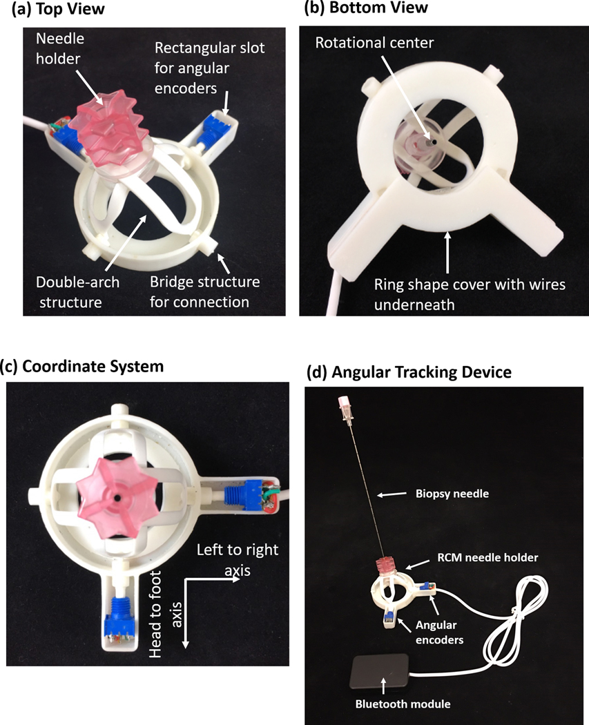
Illustration of the novel customized base and bridge structure: (a) top view, (b) bottom view, (c) coordinate system. Two rectangle slots house the potentiometers, the ring-shaped slot is used to hold the connection wires, and the bridge structure is used to connect the shafts of the potentiometers with the arch structure. (d) The modified tracking device and control box. The base is modified so that two angular encoders can be installed to track the angular motion of the needle. The Bluetooth module is responsible for data transmission
The needle holder portions are disposable, and includes potentiometers, an arch structure, and a redesigned base. However, the control box can be reused. The control box can be separated from the needle holder part as they are connected with a plug-in cable as shown in Figure 3(d). Sterilization verification or certification was not performed in this study.
Calibration
A linear factor was applied to check and compensate the offsets in the encoder reading during the initial one-time manufacturing settings. This linear factor was calculated through a calibration procedure by using a digital sliding T-bevel (General Tools & Instruments, Secaucus, NJ, USA), which has an accuracy of 0.3°, to connect with the shaft of the potentiometer.
Open-air test
The Aurora electromagnetic tracking system (Northern Digital Inc., Waterloo, Ontario, Canada) was used for an open-air test to verify the accuracy of the newly developed needle angular tracker. The experiment setup is shown in Figure 4(a). An electromagnetically tracked needle, which had an electromagnetic sensor in the tip, was inserted into the needle angular tracker to calculate the tracking error. During the experiment, the error was defined as the difference between the angulation from the Aurora system (estimated “ground truth”) and the angulation displayed on the novel custom smartphone app. The head-foot direction and left-right direction were tested independently. In total, ten points were measured in each direction.
Figure 4.
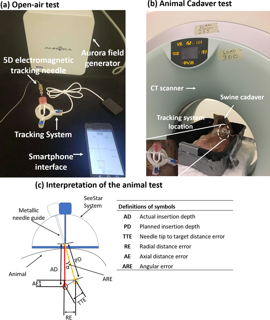
Experiment setup for (a) open-air test and (b) animal test. (c) Interpretation of the animal test. The orange line and red line indicate the planned insertion pathway and actual insertion pathway, respectively. The orange rectangle and red circle are the position of the target and needle tip, respectively.
Animal cadaver test
A swine cadaver with implanted fiducial markers and non-respiration simulation was used to validate the needle angular tracker. A 20-gauge needle was placed towards the previously implanted target markers. During the experiment, a CT scan was taken first to find the approximate positions of the target markers. Then the custom needle angular tracker was fixed to the animal skin at an estimated skin insertion site. Another CT scan was taken, and the angle was measured on the standard CT workstation (in Figure 4 (c)) with the standard CT console software. Then, this angle was manually entered into the custom smartphone app by the operator. Finally, the metallic needle guide was navigated to the target position based on the measured angulation and depth, and the needle was inserted towards the target fiducial markers. In order to reduce the effect of needle deflection during needle insertion, a hole was cut on the comparatively thick skin of the swine before needle insertion. The setup of the animal experiment is shown in Figure 4 (b).
The methodology for needle insertion accuracy assessment is seen in Figure 4 (c). The orange line (planned) and red line (actual) indicate the insertion pathways. The orange rectangle and red circle show the position of the target and needle tip, respectively. The angular error (ARE) was calculated from the axial plane on the CT image based on the needle trajectory.
Results
Open-air test
The absolute errors of the left-right angulation and head-foot angulation for each trial are shown in Figure 5 (a). The average errors were 1.03° and 1.08° with n = 10 for left-right angulation and head-foot angulation, respectively. The maximum errors for each direction were 1.3° and 1.4°, respectively. Based on the Bland-Altman plots as shown in Figure 5 (b) and (c), the left-right error and head-foot error were distributed from −1.28° to 2.38 degrees and −2.51° to 1.75° with 95% confidence intervals, respectively.
Figure 5.
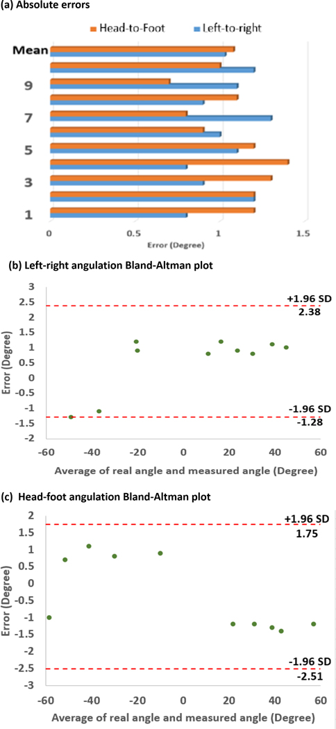
Targeting accuracy in open-air tests: (a) absolute value of errors distribution, (b) Bland-Altman plot of left-right angulation with a 95% confidence interval, (c) Bland-Altman plot of head-foot angulation with a 95% confidence interval.
Animal cadaver test
In total, three trials were conducted with the animal cadaver experiment as shown in Figure 6 (a-c). Overall, a mean angular error of 3.2° and a radial distance error of 2.9 mm were achieved after navigation with the developed needle angular tracker. The maximum angular error of 3.4° and radial distance error of 3.9 mm were achieved in trial 3 with an insertion depth of 60 mm. The radial error increased with higher insertion depth. This is likely because the needle was more subject to deflection, and/or the target marker was more likely to be moved due to the insertion force. Alternatively, it is possible that more depth of insertion gave rise to more opportunities for slight torqueing of the needle in different angles relative to the coaxial guide shaft.
Figure 6.
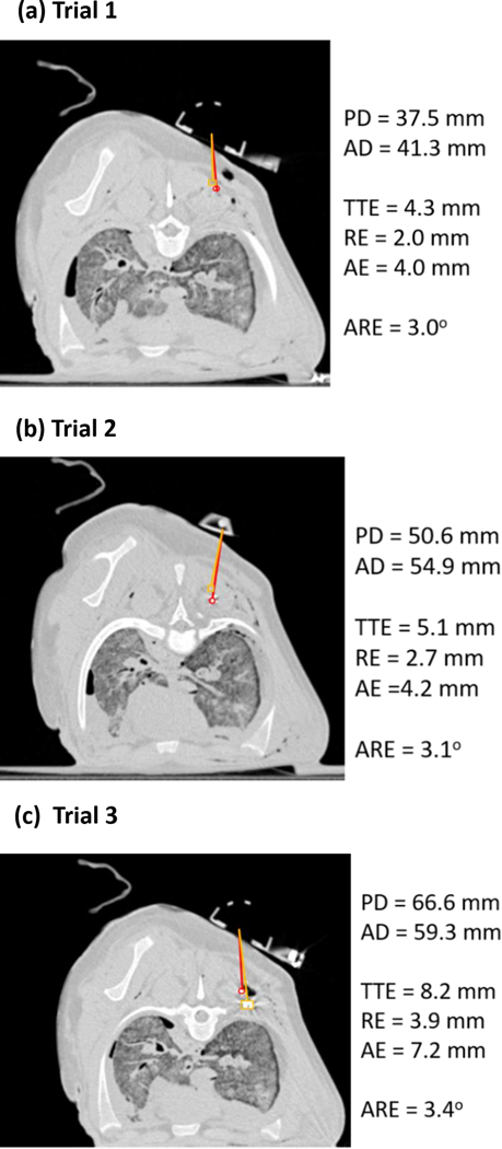
Animal test results after navigation in (a) Trial 1, (b) Trial 2, and (c) Trial 3. The orange line and red line indicate the planned insertion pathway and actual insertion pathway, respectively. The orange rectangle and red circle show the position of the target and needle tip, respectively. PD: planned insertion depth; AD: actual insertion depth; TTE: needle tip to target distance error; RE: radial distance error; AE: axial distance error; and ARE: angular error.
Discussion
Implementation data shows that the customized hardware and software system and method can be used for accurate image-guided interventions in this post-mortem setting. In addition, the presented method is immune to electromagnetic interference and, therefore, robust in CT or ultrasound procedure suites that commonly have interfering magnetic/electromagnetic instrumentation or hardware. However, several key factors may be considered to further improve the accuracy and precision of this novel system.
First, the accuracy of the developed system is mostly based on the accuracy of the potentiometer; therefore, an optimized quality potentiometer with high linearity and resolution should vastly improve the system’s accuracy. Low-cost angular encoders may exhibit nonlinearity, so calibration of the encoders before use may improve accuracy and consistency, to some extent.
Second, needle deflection also has a negative influence on accuracy. Compensation methods have been developed to correct for the effect of needle deflection, such as the beam-based needle model and the nonholonomic model, both of which could be implemented in the trajectory planning stage of this needle angular tracker system (14–19). In addition, thicker or non-beveled pencil point or diamond tip needles may be used for reaching deep-seated targets, to avoid needle bending or deviation from bevel deflection.
Third, respiration, tissue deformation, and human deployment can also affect the targeting accuracy, however are challenges for many needle-based procedures. Ventilations are held by the anesthesiologist or patients are required to hold their breath during the use of this device. In addition, since the device is most useful in the phase of initial angle selection, it is highly desirable for the device to be designed such that the needle can be released from the device after this stage, allowing the physician to adjust the needle in response to the feedback, in order to reduce targeting errors. Furthermore, the accuracy of tracking also depends on how well the device is aligned or calibrated with the CT scanner gantry laser before tracking starts.
Fourth, the tracker was mounted on the surface of skin with adhesive tape in this study. In the future, a better method such as integrated adhesive materials could be integrated to ensure the system lies flat on the skin, so that the tracker can be positioned precisely at the skin entry point.
Moreover, the work presented in this paper is a proof-of-concept study to verify the feasibility of the idea. More improvements are needed before it can be commercialized, such as selecting a potentiometer with highly consistent linearity in a large volume, redesigning the holder and base to better fit wires, and making the software more user-friendly. In addition, before it can be made commercially available, more critical animal and human trials need to be conducted for evaluation purposes within clinical regulatory requirements, such as provided by the Food and Drug Administration in the United State, Medical Device Regulations in Europe, and the National Medical Products Administration in China.
Conclusion
In this proof-of-concept study, an angulation tracking device was custom-designed and fabricated, built upon a redesign and customization of a commercial disposable passive needle holder. In this device, two potentiometers were connected with two arch structure axes of the passive needle holder through a bridge structure to acquire real-time angulation. A control box, including an Arduino Pro Mini, rechargeable batteries, and a wireless Bluetooth module, were used to measure needle angulation and provide communication with the custom smartphone app. The developed smartphone app was used to set the target angulation and display the real-time angulation. The open-air test showed that the average errors were 1.03° and 1.08° for left-right angulation and head-foot angulation, respectively. For the swine cadaver test, the results showed that the average angular error and radial distance error were 3.2° and 2.9 mm, respectively, which is comparable to the error of the EM tool used to acquire ground truth data. Additionally, it allows for off-axial needle insertion and the system functioned without accessing CT source data directly. Therefore, the proposed tracking method has potential for various clinical applications and image-guided therapies that may benefit from its user-friendly design and low cost. Future ergonomic and design refinements may be guided by a better understanding of in vivo functionality, sterilization requirements, and workflows, as well as operator feedback.
Acknowledgement:
This study was supported in part by Royal Society Wolfson Fellowship, the National Institutes of Health (NIH) Bench-to-Bedside Award, the NIH Center for Interventional Oncology Grant, the National Science Foundation (NSF) I-Corps Team Grant (1617340), NSF REU site program 1359095, the UGA-AU Inter-Institutional Seed Funding, the American Society for Quality Dr. Richard J. Schlesinger Grant, the PHS Grant UL1TR000454 from the Clinical and Translational Science Award Program, and the NIH National Center for Advancing Translational Sciences, the NIH Center for Interventional Oncology: Grant ZID# BC011242 & CL040015 and supported by the Intramural Research Program of the National Institutes of Health
References
- 1.Abayazid M, Vrooijink GJ, Patil S, et al. Experimental evaluation of ultrasound-guided 3D needle steering in biological tissue. Int J Comput Assist Radiol Surg. 2014;9:931–9. [DOI] [PMC free article] [PubMed] [Google Scholar]
- 2.Abolhassani N, Patel RV, Ayazi F. Minimization of needle deflection in robot-assisted percutaneous therapy. Int J Med Robot. 2007;3:140–8. [DOI] [PubMed] [Google Scholar]
- 3.Asadian A, Kermani MR, Patel RV. An analytical model for deflection of flexible needles during needle insertion. In Intelligent Robots and Systems (IROS), 2011 IEEE/RSJ International Conference on, 2011, pp. 2551–2556: IEEE. [Google Scholar]
- 4.Henken KR, Dankelman J, van den Dobbelsteen JJ, et al. Error analysis of FBG-based shape sensors for medical needle tracking. IEEE/ASME Trans Mechatron. 2014;19:1523–31. [Google Scholar]
- 5.Kochavi E, Goldsher D, Azhari H. Method for rapid MRI needle tracking. Magn Reson Med. 2004;51:1083–7. [DOI] [PubMed] [Google Scholar]
- 6.Kroes MW, Busser WM, Fütterer JJ, et al. Assessment of needle guidance devices for their potential to reduce fluoroscopy time and operator hand dose during C-arm cone-beam computed tomography–guided needle interventions. J Vasc Interv Radiol. 2013;24:901–6. [DOI] [PubMed] [Google Scholar]
- 7.Shahriari N, Heerink W, van Katwijk T, et al. Computed tomography (CT)-compatible remote center of motion needle steering robot: Fusing CT images and electromagnetic sensor data. Med Eng Phys. 2017;45:71–7 [DOI] [PubMed] [Google Scholar]
- 8.Tinguely P, Frehner L, Lachenmayer A, et al. Stereotactic Image-Guided Microwave Ablation for Malignant Liver Tumors—A Multivariable Accuracy and Efficacy Analysis. Front Oncol. 2020;10:842. [DOI] [PMC free article] [PubMed] [Google Scholar]
- 9.Lugez E, Sadjadi H, Pichora DR, et al. Electromagnetic tracking in surgical and interventional environments: usability study. Int J Comput Assist Radiol Surg. 2015;10:253–62. [DOI] [PubMed] [Google Scholar]
- 10.Magnusson A, Radecka E, Lönnemark M, et al. Computed-tomography-guided punctures using a new guidance device. Acta Radiol. 2005;46:505–9. [DOI] [PubMed] [Google Scholar]
- 11.Maier-Hein L, Franz AM, Birkfellner W, et al. Standardized assessment of new electromagnetic field generators in an interventional radiology setting. Med Phys. 2012;39:3424–34. [DOI] [PubMed] [Google Scholar]
- 12.Paolucci I, Schwalbe M, Williamson T, et al. Design and implementation of a navigation system for laparoscopic tumor ablation based on intraoperative US. In: 15th Annual Meeting of the German Society for Computer and Robot Assisted Surgery. Bern. 29.09.−01.10.2016. [Google Scholar]
- 13.Zhang Z, Shao G, Zheng J, et al. Electromagnetic navigation to assist with computed tomography-guided thermal ablation of liver tumors. Minim Invasive Ther Allied Technol. 2019. [E-pub ahead of print August 9, 2019]. [DOI] [PubMed] [Google Scholar]
- 14.Park W, Kim JS, Zhou Y, et al. Diffusion-based motion planning for a nonholonomic flexible needle model. In Robotics and Automation, 2005. ICRA 2005. Proceedings of the 2005 IEEE International Conference on, 2005, pp. 4600–4605: IEEE. [Google Scholar]
- 15.Pourtaherian A, Zinger S, de With P, et al. Gabor-based needle detection and tracking in three-dimensional ultrasound data volumes. In Image Processing (ICIP), 2014 IEEE International Conference on, 2014, pp. 3602–3606: IEEE. [Google Scholar]
- 16.Roberts C, Morrison W, Deely D, et al. Use of a novel percutaneous biopsy localization device: initial musculoskeletal experience. Skeletal Radiol. 2007;36:53–7. [DOI] [PubMed] [Google Scholar]
- 17.Vrooijink GJ, Abayazid M, Misra S. Real-time three-dimensional flexible needle tracking using two-dimensional ultrasound. In Robotics and Automation (ICRA), 2013 IEEE International Conference on, 2013, pp. 1688–1693: IEEE. [Google Scholar]
- 18.Webster III RJ, Kim JS, Cowan NJ, et al. Nonholonomic modeling of needle steering. Int J Rob Res. 2006;25:509–25. [Google Scholar]
- 19.Yan KG, Podder T, Xiao D, et al. An improved needle steering model with online parameter estimator. Int J Comput Assist Radiol Surg. 2006;1:205–12. [Google Scholar]


