Abstract
Low-temperature, flexible, 0–3 composite piezoelectric materials can decrease the size, cost, and complexity of high-frequency acoustic devices on temperature sensitive substrates such as those in catheter based ultrasonic devices and acoustooptic sensors. In this paper, the application of low-temperature 0–3 connected composite thick films in flexible, non-planar, high frequency ultrasonic devices is reported. A flexible high-frequency ultrasound transducer and an acousto-optic radio-frequency (RF) field sensor are demonstrated utilizing PZT-based composite thick films. Flexible composite films have been fabricated with thicknesses between 20–100μm utilizing screen-printing, stencil-printing, and dip-coating techniques. Composite films’ piezoelectric d33 coefficient is measured, with results between 35–43 pC/N. Ultrasonic transducers utilizing these films demonstrate broadband acoustic response. A composite transducer is fabricated on flexible polyimide and wrapped around a 3mm catheter. Pulse-echo experiments demonstrate viability of these films as both as an actuator and a sensor in flexible devices. The composite material is further dip-coated onto an optical fiber Bragg grating to form a flexible acousto-optic RF field sensor. The sensor demonstrates RF field sensing in the 20–130 MHz range. The results from these experiments indicate significant potential for future flexible, high frequency ultrasonic devices utilizing low temperature 0–3 composite piezoelectric materials on temperature sensitive substrates.
Keywords: Acousto-optic, composite piezoelectric, flexible, high-frequency, intravascular ultrasound, low-temperature
Graphical Abstract
I. Introduction
MOST interventional high frequency ultrasonic devices operating in the 10–80MHz range such as those used for intravascular and intracardiac ultrasound imaging are catheter based and are formed on flexible non-planar substrates [1]. Optical fibers are also frequently used as part of flexible interventional devices such as optical coherence tomography catheters [2]. Most recently, acousto-optic sensors for magnetic resonance imaging (MRI) have been introduced which also use optical fibers and integrated ultrasonic transducers operating in the 20–130MHz range [3], [4]. The flexible, non-planar nature of these devices, in addition to the processing temperature limitations of the commonly used catheter materials such as plastics and polymers, impose challenges in design and fabrication of high frequency ultrasound transducers that conform to these structures [5].
Several piezoelectric materials are suitable for conformal coating over round surfaces at low temperatures. Zinc Oxide (ZnO) films, for instance, have been sputtered onto cylindrical surfaces like optical fibers at room temperatures [6]. These films are suitable for very high frequency acousto-optical modulators [7] in the several hundred megahertz to GHz range – however sputtering thick films for devices operating in the 10–200MHz range is challenging. Alternatively, conformal ceramic and single crystal thick films, such as those based on PZT or PMN-PT powders, have been developed based on sol-gel methods for modulators and ultrasonics in the investigated frequency range [5][8]. As with other ceramic and single-crystal films, these films require a high temperature (exceeding 600°C) sintering process that may be damaging to temperature sensitive substrates such as polymers or optical structures. ceramic and single-crystal films are also rigid, limiting device flexibility after deposition. Low-temperature, flexible high frequency devices have been achieved utilizing bonded [9] or extruded [10] polymer piezoelectric films such as PVDF. Polymer piezoelectric films benefit from flexibility, low temperature processing conditions, and tunable thicknesses for a range of broadband operating frequencies [11], but polymer-based transducers such as PVDF suffer from low transmission efficiency compared to their ceramic and single-crystal counterparts, resulting in poorer pressure generation [12].
Piezoelectric ceramic-polymer composites were created to preserve the mechanical versatility of the polymer composite matrix, while benefiting from the higher piezoelectric performance of the ceramic inclusions [13]. 1–3 connected ceramic polymer composites have been widely demonstrated in ultrasonics as flexible transducers with increased transmission higher piezoelectric coefficients and transmission efficienies; however, the fabrication and integration of these films is non-trivial, usually requiring intensive dice-and-fill fabrication [14][15]. Low-temperature 0–3 composites have been introduced to offer better versatility in deposition and application. Previously reported low-temperate, 0–3 composite films have been fabricated on flexible substrates with thicknesses greater than 100 μm for sub-megahertz ultrasonic applications such as structural health monitoring, energy harvesting, and smart textiles [16], but these materials have not been demonstrated in high frequency ultrasonic applications where thinner piezoelectric films and suitable metallization layers are needed. The benefits of low temperature 0–3 composite materials – namely the low processing temperatures, diversity in deposition methods, and mechanical flexibility – make them viable candidates for implementation in high-frequency ultrasound catheters and acousto-optic sensors mentioned above due to their flexibility and potentially conformal deposition.
In this work, a 0–3 PZT-based composite material PiezoPaint™ (CTS Ferroperm™, Denmark) is used to fabricate high frequency thick film acoustic transducers at low temperatures. Transducers in the 20–100μm thickness range are fabricated using conventional screen- and stencil-printing, as well as dip coating, and film topology is investigated. Piezoelectric properties of the films are characterized through d33 piezoelectric coefficient measurement, while ultrasound transmission properties are studied utilizing hydrophone and pulse echo measurements. The composite material is then incorporated into both a fully flexible single element ultrasound transducer on a catheter and into an optical fiber based acousto-optic RF field sensor to demonstrate the functionality and versatility of novel 0–3 composite piezoelectric materials in different high frequency ultrasonic applications.
II. Materials and Methods
A. PiezoPaint™ 0–3 Composite Material
PiezoPaint™ is composed of a hard PZT material, Meggitt’s Ferroperm™ Pz24, that has been ground into a ceramic powder and is suspended in a fluoride-based polymer matrix. On its own, Pz24 is a low dielectric constant and low dielectric loss piezoelectric material with high piezoelectric voltage constant [17]. The resultant composite benefits from the ceramic material’s properties, demonstrating higher piezoelectric coefficient and dielectric constant than thick film piezopolymers such as PVDF, while maintainng a low tangent loss (tan(δ)) of 0.035. Manufacturer specified properties are shown below in Table 1, alongside commonly used high frequency ultrasonic transducer materials, as well as the Pz24 material used as the inclusion phase in the PiezoPaint™ composite. The wide variety in material properties available in high frequency ultrasonics is illustrated, and the tradeoffs between low and high piezoelectric coefficients and acoustic impedances are clearly visible.
TABLE 1:
Relevant properties of some of the widely used high-frequency ultrasonic materials.
| Property | PVDFa,b | P(VDF-TrFE)c,d | PZT-5Ac,e | PZT-5Ha,e | Pz24f | LiNbO3g,h | PiezoPaint™i |
|---|---|---|---|---|---|---|---|
| Relative Dielectric Permittivity | 6.0 | 5.0 | 1200 | 1470 | 400 | 85 | 100 |
| Acoustic Impedance (MRayl) | 3.9 | 4.5 | 33.7 | 30 | - | 34.1 | 13.9 |
| Density (kg/m3) | 1,780 | 1,880 | 7,750 | 7,500 | 7,700 | 4,650 | 5,000 |
| Piezoelectric Coefficient - d33 (pC/N) | 30–33 | 28–36 | 350 | 585 | 190 | 6.0 | 45 |
The primary advantage of PiezoPaint™ compared to previously reported 0–3 composites are the low processing temperatures around 100°C. Low-temperature 0–3 composites have been developed largely for sub-MHz operation, corresponding to film thicknesses in excess of 100μm. High frequency 0–3 composite devices have been reported; however, these utilize high temperature sintering processes [26]. High frequency, low-temperature 0–3 composite films with sub-100μm thicknesses have not been previously reported. The fabrication of sub-100 μm films at low temperatures, as described in the following section, allows the incorporation of high frequency composite transducers on non-planar geometries and on temperature sensitive substrates.
B. High Frequency Transducer Fabrication
In this study, we have employed a simple methodology for fabricating 0–3 composite transducers using conventional screen-printing, stencil-printing, and dip-coating manufacturing techniques. Screen-printing is an ink printing technique in which material is pressed through an emulsion-patterned mesh. We have utilized a 40 μm mesh size to achieve acceptable printing resolution. Stencil-printing replaces the mesh openings with a single, large feature stencil; pressing material through the stencil opening gives good control over film thickness, as the material is removed at a fixed height from the substrate. Dip-coating is a deposition process which utilizes viscous forces, allowing a material film to adhere to the surface of a substrate as it is removed from a reservoir of the coating material. The film can then be cured based on material specification, resulting in highly uniform films.
Transducers were fabricated utilizing a conductive silver ink (AG-510 Silver Conductive Ink, Kayaku Advanced Materials Inc.) to screen-print the transducer’s electrodes, while the composite film is deposited via stencil-printing. The fabrication procedure for high frequency, planar transducers is as follows: First, a 5 μm thick silver ink electrode is screen-printed on a 1mm thick glass substrate. The silver ink is cured on a 130°C hot plate for 5 minutes. A 50 μm thick stainless-steel stencil is then used to deposit a 4 mm2 composite film, which is cured on a 120°C hot plate for 10 minutes. A silver ink top electrode is printed and cured just as the first electrode, and each electrode lead is wired to an SMA connection, forming the transducer shown in Fig. 1. The transducer is connected to a high-voltage power supply and poled with a DC 5 kV/mm electric field for 15 minutes at 130°C before being allowed to cool to room temperature under the 5 kV/mm electric field.
Fig. 1.
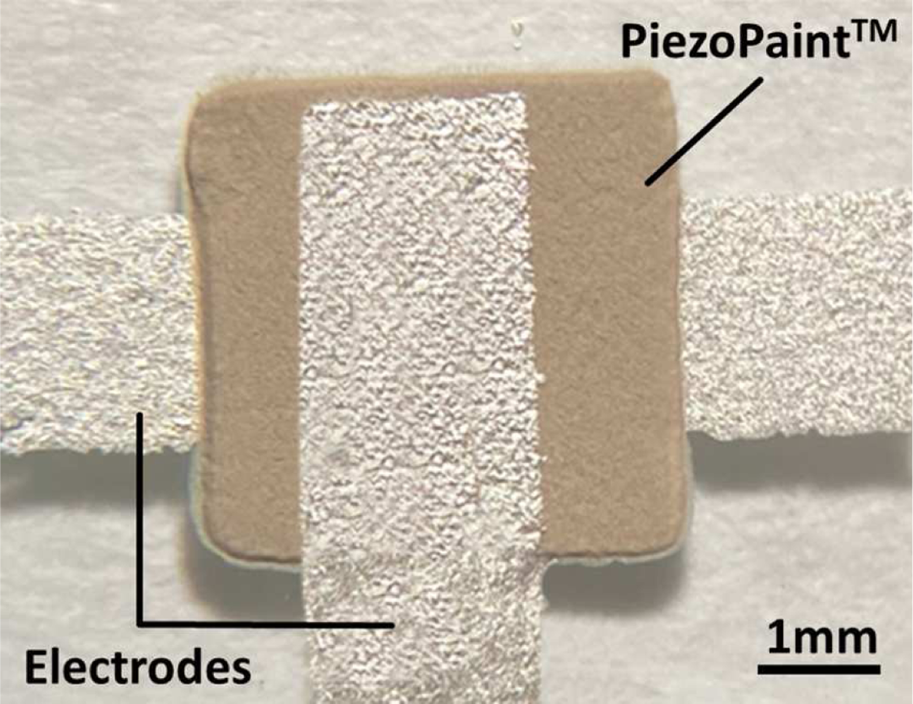
Micrograph of a stencil-printed composite transducer on glass substrate.
C. Film Characterization
Various film and transducer properties are measured to validate the feasibility of sub-100μm low temperature 0–3 composite films for high frequency applications. A white-light interferometer (VK-X3000, Keyence Corp. of America, USA) is used for 3-dimensional profilometry of films deposited via screen- and stencil-printing, and measured profiles are used to determine optimal deposition methods for film smoothness. Longitudinal piezoelectric coefficient (d33) is measured using a d33 meter (YE2730A, APC International, Ltd., USA) to quantify the piezoelectric performance and compared against existing literature. Acoustic actuation performance of composite films is characterized using the setup shown in Fig. 2. A hydrophone (HGL-0200, Onda Corp., USA) with pre-amplifier (AG-2010, Onda Corp., USA) is used to capture the temporal acoustic response of the composite film transducer. The transducer is driven by a pulser-receiver module (Panametrics 5072PR, USA), and the acoustic response is measured by the hydrophone 1 mm from the transducer. The transducer and hydrophone are terminated through 50 Ohm coaxial cables to an oscilloscope (PicoScope 6824E, Pico Technology, United Kingdom). Acoustic experiments were conducted submerged in 3M™ Fluorinert™ FC-70, a non-conductive fluid with acoustic impedance close to water (having density of 1940kg m−3 and sound velocity of 690 m/s, as the transducers are fabricated with no electrical isolation. FC-70 is a more attenuative fluid than water; however, in the millimeter range paths explored, this attenuation is not significant. A 3μm thick parylene coating, which has been shown to have negligible effect on output [27], could be used as an isolation layer for in-vivo application; however, this step was omitted for initial experimentation.
Fig. 2.
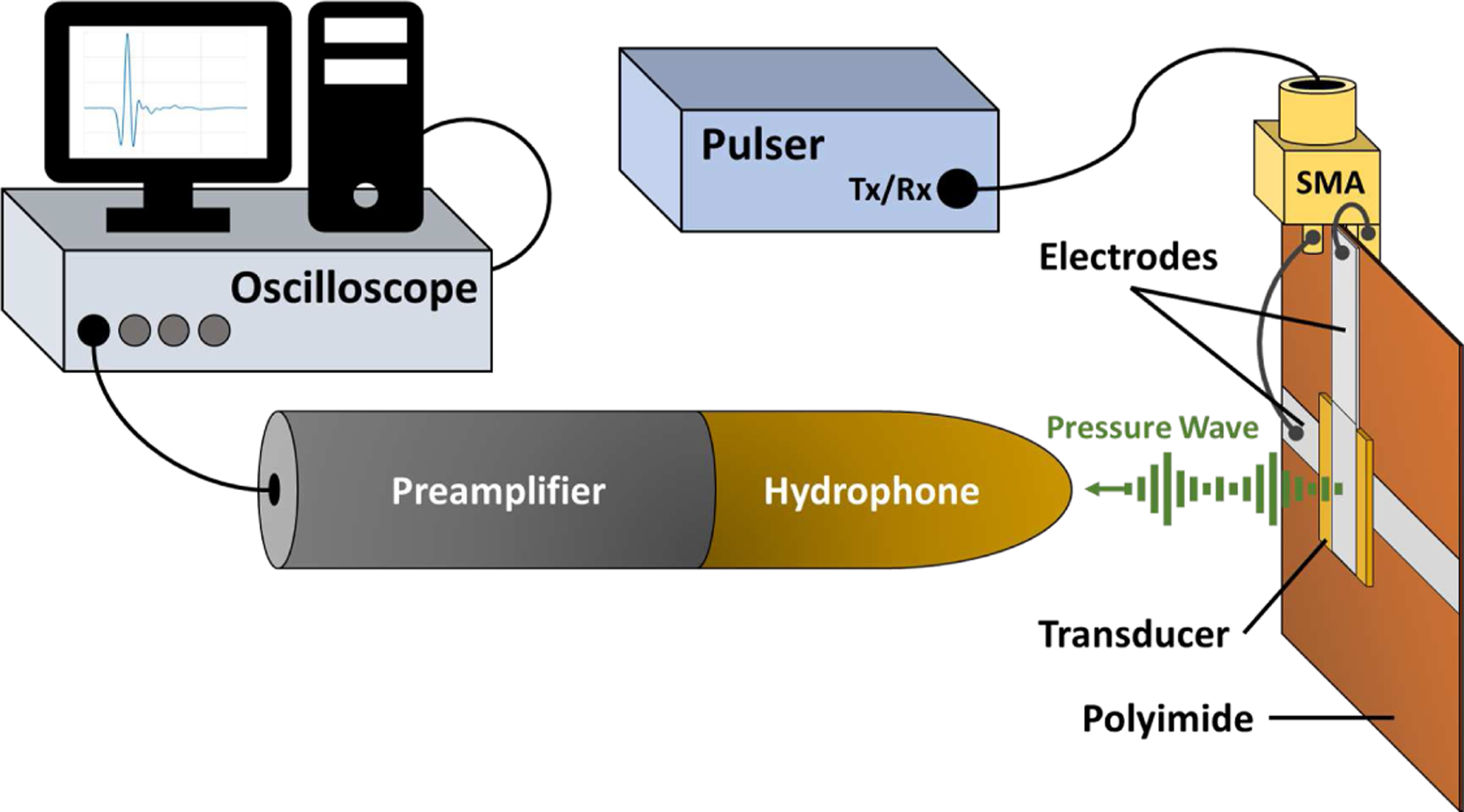
Experimental setup schematic for measuring the acoustic transmission response of the piezo film on a polyimide substrate.
D. 0–3 Composite Films for High Frequency Wrapped Transducers
Flexibility of 0–3 composite films enables deposition on flexible substrates for implementation on non-planar surfaces. Compared to 1–3 and 2–2 composite films, which are fabricated using more complex methods and later integrated, the simpler fabrication allows entire devices to be realized directly on flexible substrates. For catheter-based applications, devices may be fabricated on flexible substrates and wrapped around a catheter.
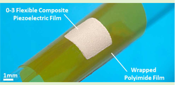
Leveraging the flexibility of the 0–3 composite films, the planar transducer structure as described in section 2 is fabricated on a 25μm thick polyimide film. The resultant transducer consists of a 50 μm thick, 1mm2 film having an active area of 500 × 500 μm. The transducer is poled at 7 kV/mm – found to be the maximum achievable poling voltage before film degradation – and is wrapped around a 9 Fr (3mm diameter) catheter, forming the device shown in Fig. 3. The curved transducer on catheter is submerged in FC-70. A hydrophone, placed 1.5mm away, captures the transducer’s acoustic response to a short pulse. Finally, a pulse-echo measurement was demonstrated using a steel bar, also 1.5 mm from the transducer, as a reflector.
Fig. 3.
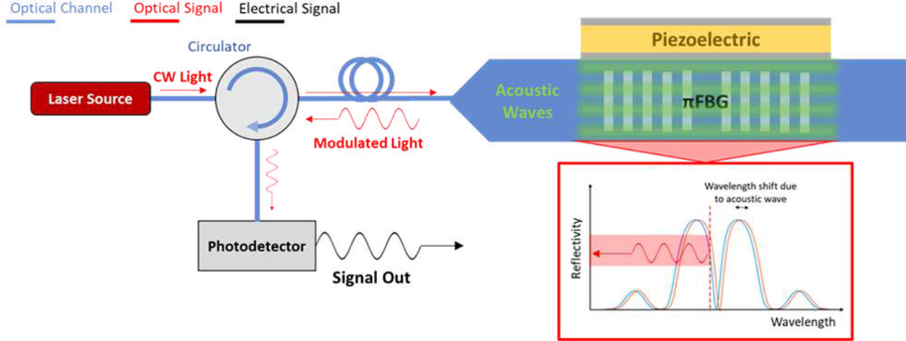
Schematic of acousto-optic RF field sensor system [4].
E. 0–3 Composite Films for Acousto-Optic Sensors
Beyond the traditional planar structure of piezoelectric films, the versatility of the low temperature 0–3 composite material allows for complex structure fabrication on sensitive substrates. We have previously developed an acousto-optic (AO) RF field sensor consisting of a large piezoelectric crystal mechanically coupled to a fiber Bragg grating (FBG) – a strain dependent optical mirror structure written into an optical fiber – for real time RF field measurement during magnetic resonance imaging (MRI) (Fig. 4). The system is described in detail in [28]. In short, the AO sensor couples the radiated RF fields used in imaging sequences into an antenna, which in turn actuates a piezoelectric element. Resultant acoustic waves couple into the fiber, producing a periodic strain on the FBG. The FBG’s reflectivity spectrum shifts with this strain, producing a modulated optical output at the receiving end that is proportional to the RF field input. RF fields in clinical MRI scanners typical range from 20 MHz to 120 MHz, falling in the high frequency range for ultrasonic transducers.
Fig. 4.
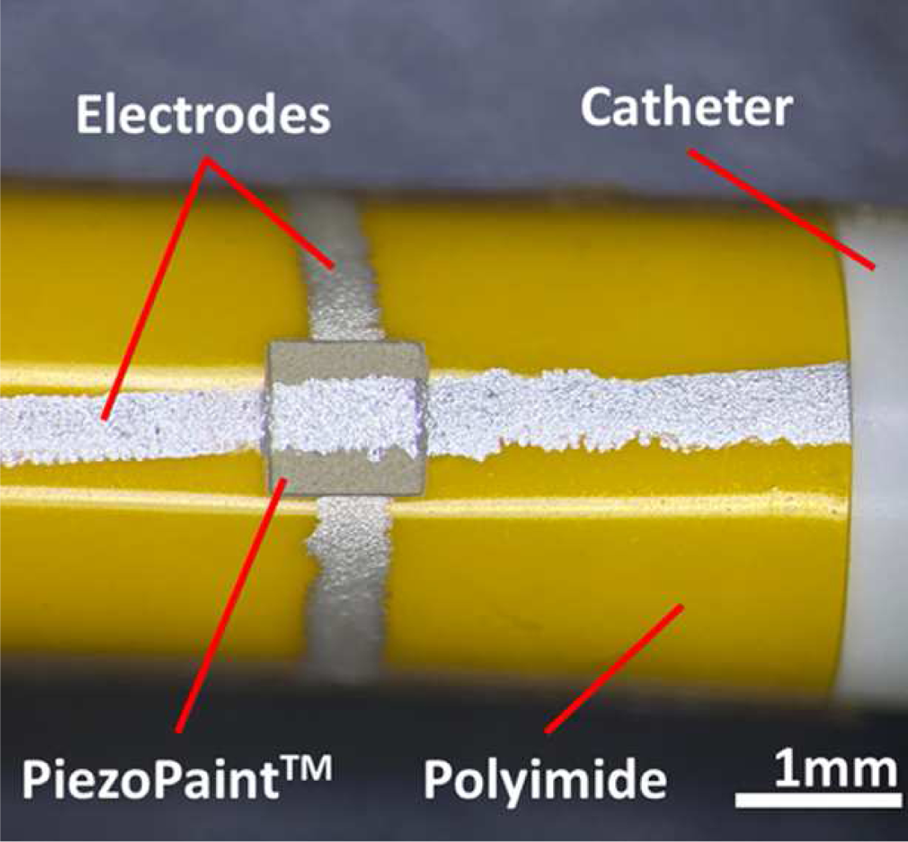
Micrograph of the piezo film transducer on polyimide substrate wrapped around a 9F catheter tube.
Size of the previously presented AO device may be reduced by replacing the bulk piezoelectric crystal with a conformal composite piezoelectric film, simultaneously increasing the acoustic coupling between the transducer and optical fiber. A silver ink electrode is screen-printed onto the fiber cladding in the FBG region and cured. Conformal films were achieved by dip-coating a thinned, low viscosity form of the precursor composite paste on the optical fiber. The composite paste is thinned to a liquid consistency using a solvent thinner (DuPont Micromax™ 8210), and dip-coated onto the fiber. The coated fiber is suspended 1 mm above a 130°C hot plate and allowed to cure for 15 minutes. A top electrode is again screen-printed onto the film and cured to finalize the transducer, shown in Fig. 5(a). The bottom electrode is revealed by mechanically removing the composite film from the fiber’s distal end, and electrical connections are made to both the top and bottom electrodes. A Cross sectional scanning electron microscope (SEM) image, depicted in Fig. 5(b), shows a film thickness of 35 μm, yielding a sensor with total diameter under 200 μm. The device is then poled with a conservative 3 kV/mm to ensure no breakdown occurs between electrodes.
Fig. 5.
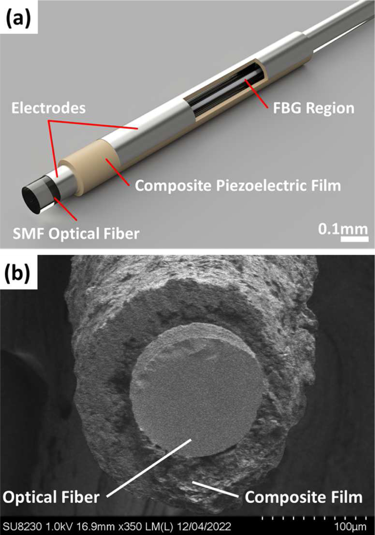
Rendering of the AO sensor with dip-coated 0–3 composite piezoelectric film B) Cross sectional SEM image of the AO sensor.
The conformal transducer’s acoustic response is measured via hydrophone using the setup described previously; A signal generator (Keysight 33600A) is used to apply a 1 Vpp 8ns long pulse to the transducer and the acoustic response is captured 1.5 mm away. The acoustic response in the FBG region is measured optically by probing the FBG with a laser while the transducer is driven by the same 1 Vpp, 8ns pulse. Fast Fourier transform of the modulated optical output is used to determine the acoustic frequency response of the AO sensor.
To demonstrate electric field sensing capability of the sensor with the composite film transducer, electrical connection to the electrodes are removed and the acousto-optic sensor is placed inside a transverse electromagnetic (TEM) cell (TekBox TBTC2, Singapore). The TEM cell generates a uniform electric field between its septum and ground plates, simulating the RF fields present during a MRI scan. Electric field amplitudes ranging between 0–1000 V/m, which are typical values in MRI, are generated by the signal generator connected to the TEM cell through a power amplifier (ENI 5100L, USA). The TEM cell was driven to produce a 500 V/m field at common clinical MRI operating frequencies of 23.6 MHz (0.55T Siemens MAGNETOM Free.Max), 63.8 MHz (1.5T Siemens MAGNETOM Aera), and 123 MHz (3T Siemens MAGNETOM Skyra) to demonstrate the functionality of the conformally coated acousto-optic sensor for different MRI systems.
Similarly, to demonstrate magnetic field sensing capabilities, the transducer electrodes are connected to a 5-turn coil antenna wrapped around a 1.6mm diameter tube. (Fig. 6), and the sensor is placed inside an 18 turn, 25mm diameter solenoid coil. The coil simulates a homogeneous magnetic field when connected to the signal generator through the power amplifier. The magnetic field was measured inside the solenoid coil using a magnetic field probe (100B EMC Probe, Beehive Electronics, CA, USA) at the same common MRI operating frequencies. The magnetic field was calculated to be 26mT at 23.6 MHz, 760mT at 63.86 MHz, and 1.56T at 123 MHz. Under these conditions, magnetic field sensing utilizing the acousto-optic sensor is demonstrated.
Fig. 6.

Schematic of a) Electric Field and b) Magnetic Field Experimental Setups.
III. Results
A. Film Characterization
For comparable film thicknesses, surface roughness of screen-printed films is larger than that of stencil printed films due to the screen’s mesh. Fig. 7 illustrates surface profilometry measurements of a 53 μm thick screen printed and 51 μm thick stencil printed composite film. The effects of the screen are directly visible where the peaks and valleys form uniform rows across the film. The average roughness over a 1mm2 area for the screen-printed film is 4.2 μm, compared to 1.8 μm for the stencil-printed film. The lowest valleys in the stencil printed film reach 10 μm below the mean thickness, while this value is below 5 μm for stencil-printed films and occur less frequently. In thinner stencil-printed films, these valleys prevent consistent poling at high amplitude electric fields. The thinner points of the piezoelectric layer are exposed to electric fields exceeding the breakdown threshold of the film, causing a short circuit and damaging the film. Stencil printed films do not exhibit the extreme periodic valleys and hills produced by the screen mesh, reducing surface roughness and allowing consistent transducer fabrication. Moreover, film thickness was more precisely controlled when stencil-printing versus screen printing. Measured d33 piezoelectric coefficients for the composite films are between 35–43 pC/N. While this represents a slight departure from the manufacturer specified 45 pC/N, the measured piezoelectric coefficient still offers an increase in performance versus a traditional polymer thick film such as PVDF. Moreover, the higher relative permittivity compared to polymer piezoelectric films is beneficial in minimizing parasitic effects in transducers. Tighter control over processing parameters such as poling conditions may help reduce the difference between the stated and measured values.
Fig. 7.
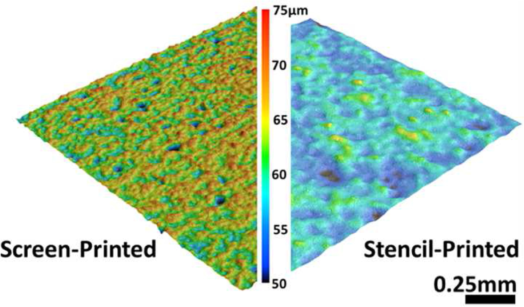
Film topology produced using optical white-light profilometry.
Acoustic actuation response of a 50 μm thick transducer is measured as described in the previous section. The temporal data captured by a hydrophone is used to plot the frequency response of the transducer, shown in Fig. 8. Here, resonance with a center frequency of 10 MHz is observed, with acoustic activity reaching 20 MHz. The effect of the thick glass substrate is clearly visible as resonant ringing across the acoustic spectrum. An envelope was generated in MATLAB® using a built-in peak envelope function – returning the local maxima separated by at least 20 data points – to better visualize the transducers acoustic response. The enveloped response suggests the composite transducer has a broadband acoustic response, with 50% 3dB fractional bandwidth.
Fig. 8.
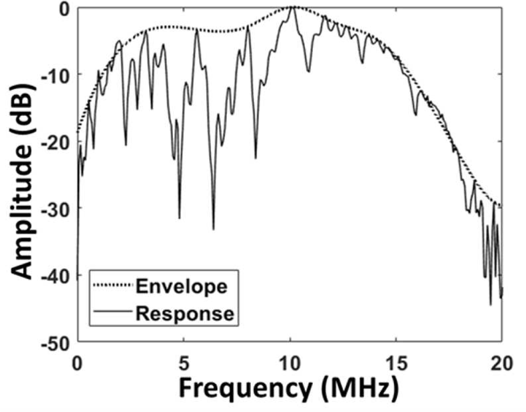
Actuation frequency response of a composite transducer as measured by a hydrophone.
B. Flexible Transducer on Polyimide
Fig. 3 shows the hydrophone measurement setup for a composite transducer on polyimide, results of which are shown in Fig. 9. The planar transducer exhibits a similar response to that of the transducer on glass, with minimal substrate ringing due to lossy polyimide film substrate. A broadband center frequency around 10 MHz is again noted, with 60% 3dB fractional bandwidth.
Fig. 9.
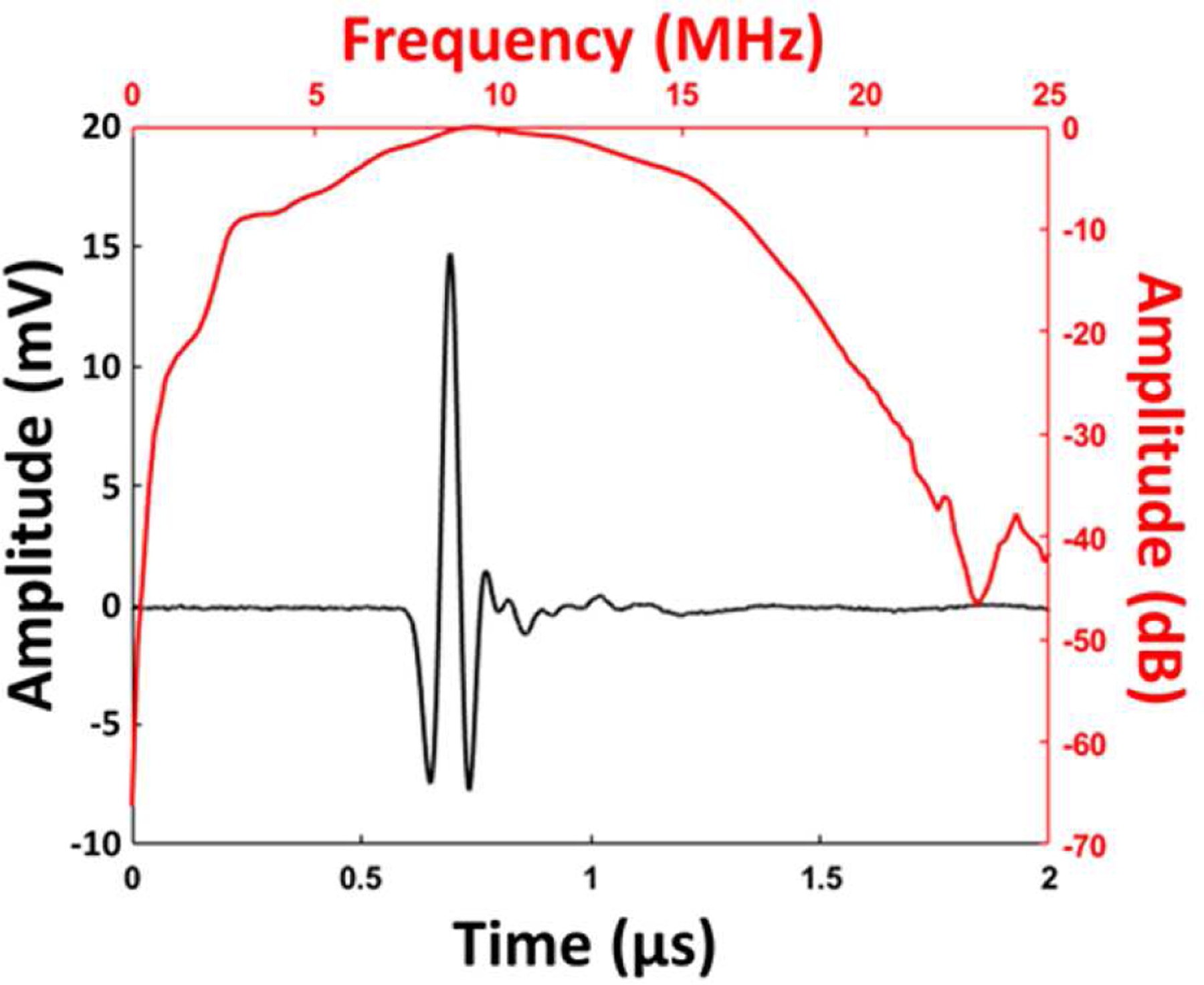
Transmit response of a 50μm thick transducer on planar polyimide film substrate.
A second transducer fabricated on polyimide was wrapped around a catheter, and the output waveform was measured by a hydrophone (Fig. 10(a)). Center frequency of the catheter-polyimide-backed transducer is shown to be 8 MHz, with broadband response. Differences in film thicknesses between transducers is due to the manual stencil printing process, resulting in small variation in center frequency and bandwidth between devices. However, the physical integrity and broadband response - fractional bandwidth is shown to be nearly 100% for the wrapped transducer - of the composite transducer are not negatively effected by bending the film. Output pressure at 8 MHz is 1.5 kPa/V, as measured by the hydrophone. Pulse-echo experiments demonstrate the composite film’s ability to sense an acoustic reflection, pictured in Fig. 10(b) – demonstrating the material’s ability to perform as both an actuator and a sensor. Micromachined substrates and electrodes may allow thinner transducers to be fabricated and minimize losses due to non-uniform and thick electrode layers, leading to better performance in both acoustic actuation and sensing with flexible devices.
Fig. 10.
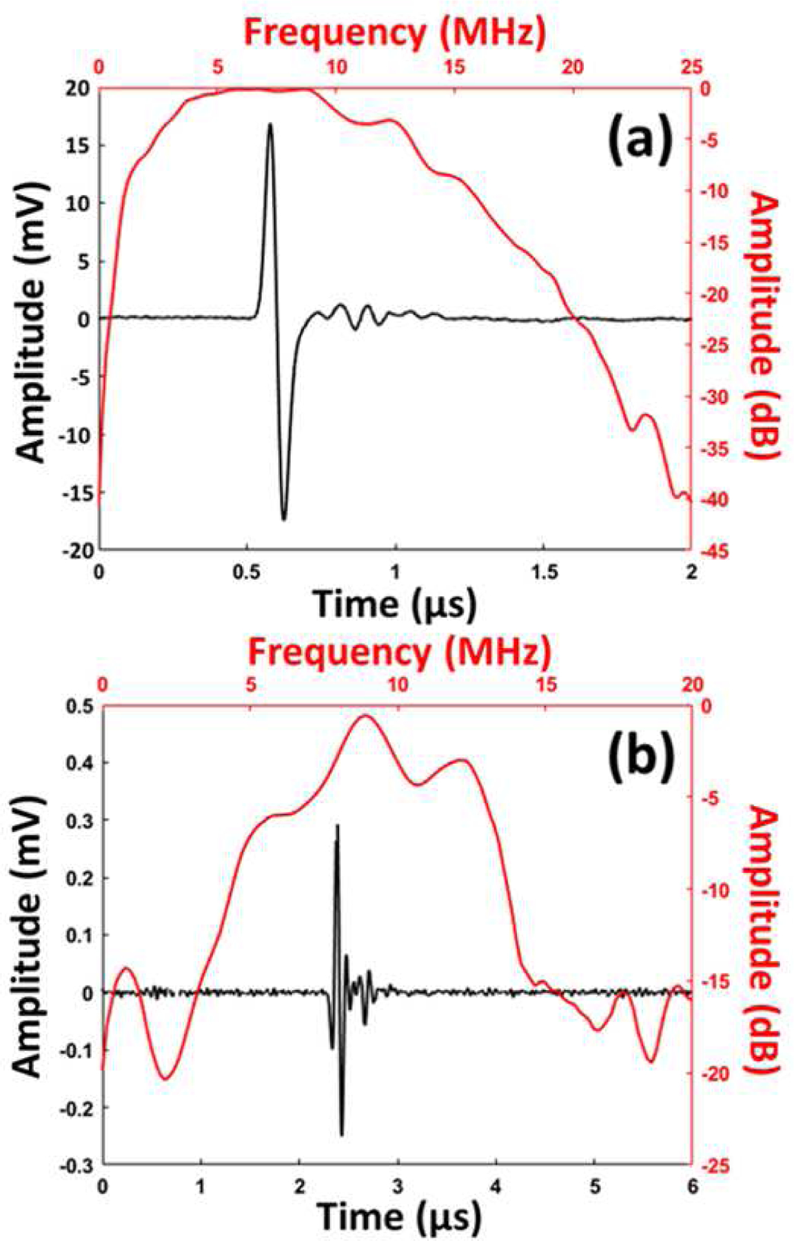
a) Wrapped transducer on catheter temporal frequency response. b) Echo measurement from steel reflector.
C. Acousto-Optic Sensor
The potential for dramatically reducing the size of the AO sensor by incorporating a 0–3 composite film is shown in Fig. 11(a), where the previous acousto-optic sensor with bulk LiNbO3 is placed next to the thick film-based sensor. The acoustic response inside the fiber (obtained through an FFT as previously described) exhibits broadband resonance from 10–40 MHz, with additional resonant activity continuing beyond 100 MHz. The radially poled conformal film and cylindrical fiber cause the complex acoustic resonances in the fiber core; focused acoustic waves generate lower frequency thickness mode resonances as well as higher frequency breathing mode resonances due to the breathing modes in the glass fiber [29].
Fig. 11.
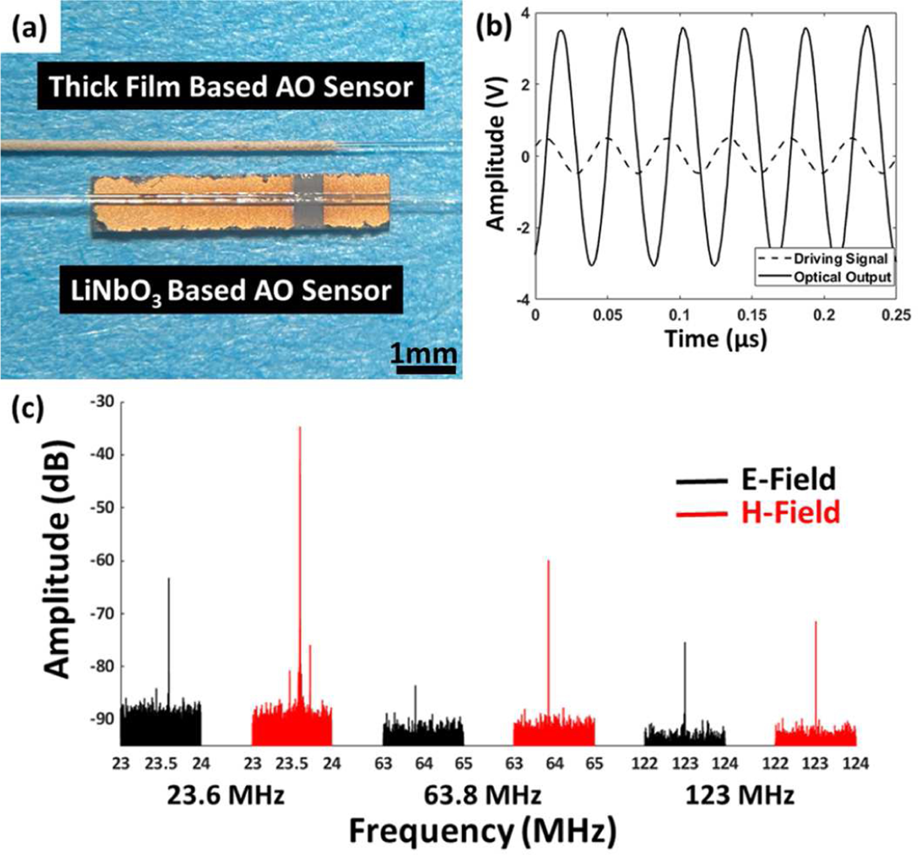
a) Miniaturization of the AO sensor using conformal composite thick film versus bulk crystal. b) AO sensor optical output due to a 23.6 MHz driving signal. c) AO sensor response to electric and magnetic fields at commonly utilized MRI frequencies.
AO sensor response to a 1Vpp 23.6 MHz input into the conformal transducer is shown in Fig. 11(b), where the modulated optical output nearly saturates the photodetector input, demonstrating strong acoustic coupling between the composite film and the fiber core. Leveraging the complex high frequency response of the sensor, we are able detect RF fields inside the TEM cell and solenoid coil across a wide range of frequencies. Fig. 11(c) illustrates the frequency response at each of the three measured frequencies – 23.6 MHz, 64 MHz, and 123 MHz – for both electric field and magnetic field measurements. Strong response at 23.6 MHz is expected, as this is near the main resonance frequency in the fiber core. The sensor was also able to detect electromagnetic fields at the higher operating frequencies of 63.86 MHz and 123 MHz with lower SNR compared to 23.6 MHz.
IV. Discussion
The results presented above indicate a significant potential for several high frequency ultrasound applications as well as to areas of improvement.
High piezoelectric coefficient materials such as PZT that have been used in previous acousto-optic modulators demand high-temperature processing, which damage the gratings in the optical fiber Bragg grating sensor and cause the glass core and cladding to become brittle and susceptible to breakage. Utilizing low-temperature 0–3 composite high-frequency films allows deposition on fibers without degradation, while offering an increase in piezoelectric coefficients when compared to previously demonstrated piezopolymer coatings. [29][30]. In addition, the performance of low temperature 0–3 connected composite piezoelectrics can be further optimized to achieve d33 coefficients in excess of 80 pC/N [31]–[33]. Although for the presented high frequency applications thickness mode actuation seems more relevant other modes – such as transverse mode d31 operation may have applications in future sensors and actuators.
In terms of processing the films for transducer applications, a challenge is achieving good film uniformity in the composite coatings. As shown by the cross section in Figure 5(b), current dip-coated films exhibit non-uniform film thickness and irregular surface roughness. Further process development may yield better uniformity throughout these composite films. Better understanding of the sensor’s acoustic properties considering the overall structure of the sensor, including the optical fiber for example, is vital for the fabrication of well-tuned acoustooptic devices. Future modeling is necessary to understand the effect of different transducer geometries on the acousto-optic sensor’s resonance frequencies – as well as the strain modes inside the fiber at these resonances, as the strain should be greatest in the core of the fiber for the highest SNR. Once these effects are well modeled and understood, acousto-optic devices can be better tuned to fit individual use cases such as the unique operating frequencies for different MRI scanners.
In terms of ultrasound imaging systems, the films produced in this study have center frequencies in the 5–10 MHz range making them readily suitable for intracardiac echocardiography (ICE) applications [34]. There is a potential for low cost and complexity by fabricating the entire device on a flexible substrate which can be simply wrapped on catheter or guidewire to realize circularly arrayed transducers. Screen-printed electrodes were utilized to simplify the fabrication process, but micromachined electrodes utilizing thin metal or metal composite films [14] can produce finer features, be more resilient under bending stresses, and generate less film roughness, allowing thinner films and finer feature-size devices. A limiting factor here is the ceramic inclusion particle size. For the PiezoPaint™ material used, average particles size is on the order of 1 μm, and should be 1/10th of the overall film thickness. This applies a lower bound on film thickness of 10μm. In the case that thinner films are desired, a 0–3 Potassium Sodium Niobate (KNN) inclusion phase, having sub-micron particle sizes, may be used. By increasing the operation frequency with thinner, higher coupling coefficient films, intravascular ultrasound (IVUS) applications may be targeted. These imaging type applications require complex integrated electronics to minimize parasitics and electrical interconnects while improving the SNR. Integrated system-on-chip type electronics recently developed for micromachined ultrasonic transducers can be utilized for this purpose [35]–[37].
V. Conclusion
In this work, we describe processes for low temperature fabrication of high frequency 0–3 composite piezoelectric films utilizing composite material PiezoPaint™ and explore its potential for several applications. Ultrasonic transducer-based devices were fabricated on temperature sensitive substrates via conventional screen-printing, stencil-printing, and dip-coating processes to demonstrate the advantages of low temperature, flexible piezoelectric films. A flexible composite film deposited on flexible polyimide was able to maintain performance and structural integrity when wrapped around a catheter structure and produce a pulse echo response with frequency response up to 20 MHz, while the transducer on fiber demonstrated RF field sensing in the 20–130 MHz range with reduced package size compared to previous sensors. Further modelling and processing advances may help produce more accurately tuned devices, offering higher operating frequencies and better performance.
Acknowledgment
Research reported in this publication was supported by National Institute of Biomedical Imaging and Bioengineering of the National Institutes of Health (R01EB029331). The content is solely the responsibility of the authors and does not necessarily represent the official views of the National Institutes of Health.
This work was supported by the National Institutes of Health under Grant R01EB029331. (Corresponding author: F. Levent Degertekin.)
References
- [1].Peng C, Wu H, Kim S, Dai X, and Jiang X, “Recent advances in transducers for intravascular ultrasound (Ivus) imaging,” Sensors, vol. 21, no. 10. MDPI AG, May 02, 2021. doi: 10.3390/s21103540. [DOI] [PMC free article] [PubMed] [Google Scholar]
- [2].Adams DC, Wang Y, Hariri LP, and Suter MJ, “Advances in endoscopic optical coherence tomography catheter designs,” IEEE Journal of Selected Topics in Quantum Electronics, vol. 22, no. 3, pp. 210–221, May 2016, doi: 10.1109/JSTQE.2015.2510295. [DOI] [Google Scholar]
- [3].Yaras YS et al. , “Acousto-Optic Catheter Tracking Sensor for Interventional MRI Procedures,” IEEE Trans Biomed Eng, vol. 66, no. 4, pp. 1148–1154, Apr. 2019, doi: 10.1109/TBME.2018.2868830. [DOI] [PMC free article] [PubMed] [Google Scholar]
- [4].Bradley LW, Yaras YS, and Degertekin FL, “Acousto-Optic Electric Field Sensor Based on Thick-Film Piezoelectric Transducer Coated Fiber Bragg Grating,” in 27th International Conference on Optical Fiber Sensors, 2022, p. F1.2. doi: 10.1364/OFS.2022.F1.2. [DOI]
- [5].Barrow DA, Lisboˆa O, Jen CK, and Sayer M, “In-line phase modulators using coaxial thick lead zirconate titanate coated optical fibers,” J Appl Phys, vol. 79, no. 6, pp. 3323–3329, 1996, doi: 10.1063/1.362661. [DOI] [Google Scholar]
- [6].Godil AA, Patterson DB, Heffner BL, Kino GS, and Khuri-Yakub BT, “All-Fiber Acoustooptic Phase Modulators Using Zinc Oxide Films on Glass Fiber,” Journal of Lightwave Technology, vol. 6, no. 10, pp. 1586–1590, 1988, doi: 10.1109/50.7919. [DOI] [Google Scholar]
- [7].Heffner BL, Risk WP, Khuri-Yakub BT, and Kino GS, “Deposition of Piezoelectric Films on Single-Mode Fibers and Applications to Fiber Modulators,” 1986 IEEE International Ultrasonics Symposium (IUS), pp. 709–713, 1986.
- [8].Jiang Z, Dickinson RJ, Hall TL, and Choi JJ, “A PZT – PVDF Stacked Transducer for Short-Pulse Ultrasound Therapy and Monitoring,” IEEE Trans. Ultrason., Ferroelectr., and Freq. Control, vol. 68, no. 6, pp. 2164–2171, 2021. [DOI] [PubMed] [Google Scholar]
- [9].Fang C, Hu H, and Zou J, “A Focused Optically Transparent PVDF Transducer for Photoacoustic Microscopy,” IEEE Sens J, vol. 20, no. 5, pp. 2313–2319, 2020, doi: 10.1109/JSEN.2019.2952971. [DOI] [Google Scholar]
- [10].Imai M, Satoh S, Sakaguchi T, Motoi K, and Odajima A, “100 MHz-Bandwidth Response of a Fiber Phase Modulator With Thin Piezoelectric Jacket,” IEEE Photonics Technology Letters, vol. 6, no. 8, pp. 956–959, 1994, doi: 10.1109/68.313063. [DOI] [Google Scholar]
- [11].Ramadan KS, Sameoto D, and Evoy S, “A review of piezoelectric polymers as functional materials for electromechanical transducers,” Smart Mater Struct, vol. 23, no. 3, 2014, doi: 10.1088/0964-1726/23/3/033001. [DOI] [Google Scholar]
- [12].Zhu BP, Wu DW, Zhang Y, Ou-Yang J, Chen S, and Yang XF, “Sol-gel derived PMN-PT thick films for high frequency ultrasound linear array applications,” Ceram Int, vol. 39, no. 8, pp. 8709–8714, 2013, doi: 10.1016/j.ceramint.2013.04.054. [DOI] [Google Scholar]
- [13].Eltouby P, Shyha I, Li C, and Khaliq J, “Factors affecting the piezoelectric performance of ceramic-polymer composites: A comprehensive review,” Ceramics International, vol. 47, no. 13. Elsevier Ltd, pp. 17813–17825, Jul. 01, 2021. doi: 10.1016/j.ceramint.2021.03.126. [DOI] [Google Scholar]
- [14].Kim T, Cui Z, Chang W-Y, Kim H, Zhu Y and Jiang X, “Flexible 1–3 Composite Ultrasound Transducers With Silver-Nanowire-Based Stretchable Electrodes,” IEEE Trans. on Industrial Electronics, vol. 67, no. 8, pp. 6955–6962, Aug. 2020, doi: 10.1109/TIE.2019.2937063. [DOI] [Google Scholar]
- [15].Li Y et al. , “PMN-PT/Epoxy 1–3 composite based ultrasonic transducer for dual-modality photoacoustic and ultrasound endoscopy,” Photoacoustics, vol. 15, p. 100138, 2019, doi: 10.1016/j.pacs.2019.100138. [DOI] [PMC free article] [PubMed] [Google Scholar]
- [16].Elkjaer K, Astafiev K, Ringgaard E, and Zawada T, “Integrated sensor arrays based on PiezoPaintTM for SHM applications,” PHM 2013 - Proceedings of the Annual Conference of the Prognostics and Health Management Society, 2013, pp. 372–380, 2013.
- [17].CTS Ferroperm Piezoceramics, “Very Hard PZT: Type Pz24,” datasheet, CTS Ferroperm: Kvistgard, Denmark, https://www.ferropermpiezoceramics.com/material/traditional-hard-pzt-for-transmitter-applications (accessed October 25th, 2022).
- [18].Shung KK, Cannata JM, and Zhou QF, “Piezoelectric materials for high frequency medical imaging applications: A review,” J Electroceram, vol. 19, no. 1, pp. 139–145, 2007, doi: 10.1007/s10832-007-9044-3. [DOI] [Google Scholar]
- [19].Sappati KK and Bhadra S, “Piezoelectric polymer and paper substrates: A review,” Sensors (Switzerland), vol. 18, no. 11, 2018, doi: 10.3390/s18113605. [DOI] [PMC free article] [PubMed] [Google Scholar]
- [20].Foster FS, Harasiewicz KA, and Sherar MD, “A history of medical biological imaging with polyvinylidene fluoride (PVDF) transducers,” IEEE Trans Ultrason Ferroelectr Freq Control, vol. 47, no. 6, pp. 1363–1371, 2000, doi: 10.1109/58.883525. [DOI] [PubMed] [Google Scholar]
- [21].You A, Be MAY, and In I, “Polarization of thick polyvinylidene fluoride / trifluoroethylene copolymer films,” J Appl Phys, vol. 3982, no. June 1998, 2020. [Google Scholar]
- [22].Hooker W, “Properties Ceramics of PZT-Based Piezoelectric Ceramics Between −150°C and 250°C,” September, 1998, https://ntrs.nasa.gov/citations/19980236888 (accessed October 25th, 2022.
- [23].Warner AW, Onoe M, and Coquin GA, “Determination of Elastic and Piezoelectric Constants for Crystals in Class (3m),” J Acoust Soc Am, vol. 42, no. 6, pp. 1223–1231, 1967, doi: 10.1121/1.1910709. [DOI] [Google Scholar]
- [24].Boston Piezo Optics Inc., “Lithium Niobate,” Boston Piezo Optics Inc: Bellingham, MA, USA, https://www.bostonpiezooptics.com/lithiumniobate (accessed November 16th, 2022). [Google Scholar]
- [25].CTS Ferroperm Piezoceramics, “PiezoPaint: A Flexible Piezoelectric material for soft substrates,” datasheet, CTS Ferroperm: Kvistgard, Denmark, https://www.ferropermpiezoceramics.com/product/piezopaint(accessed October 25th, 2022).
- [26].Pedersen T, Zawada T, Hansen K, Lou-Moeller R, and Thomsen E, “Fabrication of high-frequency pMUT arrays on silicon substrates,” IEEE Trans Ultrason Ferroelectr Freq Control, vol. 57, no. 6, pp. 1470–1477, 2010, doi: 10.1109/TUFFC.2010.1566. [DOI] [PubMed] [Google Scholar]
- [27].Jung G et al. , “Single-Chip Reduced-Wire CMUT-on-CMOS System for Intracardiac Echocardiography,” International Ultrasonics Symposium, 2018.
- [28].Yaras YS, “Acousto-Optic Sensing for Safe MRI Procedures,” Ph.D Dissertation, School of Electrical and Computer Engineering, Georgia Institute of Technology, Atlanta, GA, USA, 2022. [Google Scholar]
- [29].Ku CC, DePaula RP, Jarzynski J, and Bucaro JA, “High Frequency Response of a Single Mode Fiber Optical Phase Modulator High Frequency Response of a Single Mode Fiber Optical Phase Modulator Utilizing a Piezoelectric Plastic Jacket,” Fiber Optic and Laser Sensors I, vol. 0412, no. September 1983, pp. 178–185, 1983, doi: 10.1117/12.935814. [DOI] [Google Scholar]
- [30].Jarzynski J, “Frequency response of a single-mode optical fiber phase modulator utilizing a piezoelectric plastic jacket,” J Appl Phys, vol. 55, no. 9, pp. 3243–3250, 1984, doi: 10.1063/1.333382. [DOI] [Google Scholar]
- [31].Poon YM, Ho CH, Wong YW, and Shin FG, “Theoretical predictions on the effective piezoelectric coefficients of 0–3 PZT/Polymer composites,” J Mater Sci, vol. 42, no. 15, pp. 6011–6017, 2007, doi: 10.1007/s10853-006-0984-9. [DOI] [Google Scholar]
- [32].Tiwari V and Srivastava G, “Structural, dielectric and piezoelectric properties of 0–3 PZT/PVDF composites,” Ceram Int, vol. 41, no. 6, pp. 8008–8013, Jul. 2015, doi: 10.1016/j.ceramint.2015.02.148. [DOI] [Google Scholar]
- [33].Bowen CR and Topolov VY, “Piezoelectric sensitivity of PbTiO3-based ceramic/polymer composites with 0–3 and 3–3 connectivity,” Acta Mater, vol. 51, no. 17, pp. 4965–4976, 2003, doi: 10.1016/S1359-6454(03)00283-0. [DOI] [Google Scholar]
- [34].Han Z et al. , “Phased-Array Transducer for Intracardiac Echocardiography Based on 1–3 Piezocomposite,” Front Mater, vol. 8, no. April, pp. 1–12, 2021, doi: 10.3389/fmats.2021.663926. [DOI] [Google Scholar]
- [35].Jung G et al. , “A Reduced-Wire ICE Catheter ASIC with Tx Beamforming and Rx Time-Division Multiplexing,” IEEE Trans Biomed Circuits Syst, vol. 12, no. 6, pp. 1246–1255, 2018, doi: 10.1109/TB-CAS.2018.2881909. [DOI] [PMC free article] [PubMed] [Google Scholar]
- [36].Lim J, Tekes C, Arkan EF, Rezvanitabar A, Degertekin FL, and Ghovanloo M, “Highly Integrated Guidewire Ultrasound Imaging System-on-a-Chip,” IEEE J Solid-State Circuits, vol. 55, no. 5, pp. 1310–1323, 2020, doi: 10.1109/JSSC.2020.2967551. [DOI] [PMC free article] [PubMed] [Google Scholar]
- [37].Rezvanitabar A et al. , “Integrated Hybrid Sub-Aperture Beamforming and Time-Division Multiplexing for Massive Readout in Ultrasound Imaging,” IEEE Trans Biomed Circuits Syst, vol. 16, no. 5, pp. 972–980, 2022, doi: 10.1109/TBCAS.2022.3205024. [DOI] [PMC free article] [PubMed] [Google Scholar]


