

ABSTRACT
Improving the damage tolerance and reliability of ceramic artificial bone materials, such as sintered bodies of hydroxyapatite (HAp), that remain in vivo for long periods of time is of utmost importance. However, the intrinsic brittleness and low damage tolerance of ceramics make this challenging. This paper reports the synthesis of highly damage tolerant calcium phosphate-based materials with a bioinspired design for novel artificial bones. The heat treatment of isophthalate ion-containing octacalcium phosphate compacts in a nitrogen atmosphere at 1000°C for 24 h produced an HAp/β-tricalcium phosphate/pyrolytic carbon composite with a brick-and-mortar structure (similar to that of the nacreous layer). This composite exhibited excellent damage tolerance, with no brittle fracture upon nailing, likely attributable to the specific mechanical properties derived from its unique microstructure. Its maximum bending stress, maximum bending strain, Young’s modulus, and Vickers hardness were 11.7 MPa, 2.8 × 10‒2, 5.3 GPa, and 11.7 kgf/mm2, respectively. The material exhibited a lower Young’s modulus and higher fracture strain than that of HAp-sintered bodies and sintered-body samples prepared from pure octacalcium phosphate compacts. Additionally, the apatite-forming ability of the obtained material was confirmed in vitro, using a simulated body fluid. The proposed bioinspired material design could enable the fabrication of highly damage tolerant artificial bones that remain in vivo for long durations of time.
KEYWORDS: Octacalcium phosphate, hydroxyapatite, β-tricalcium phosphate, damage tolerance, bioinspired material design, nacreous layer
GRAPHICAL ABSTRACT

IMPACT STATEMENT
Synthesis of hydroxyapatite/β-tricalcium phosphate/pyrolytic carbon composites with excellent damage tolerance as promising new artificial-bone materials.
1. Introduction
Improving the damage-tolerance properties and reliability of ceramic structural materials is of significant importance [1,2]. Therefore, several studies have attempted to improve the properties of such materials [3–7], including ceramic biomaterials [8,9], which can be regarded as structural materials. In the early stages of artificial bone development, glass (with a specific composition that bonds directly to bone) was used as artificial bone [10]. Subsequently, glass-ceramic materials (which bond with bones) were proposed to overcome the low strength and toughness of glass [11]. Glass-ceramics containing mica were developed to improve brittleness and enable the formation of machinable artificial bones [12]. The history of artificial-bone development is similar to that of ceramic structural materials, with the additional consideration of biocompatibility. Research on glass-based artificial bones is ongoing, with particular emphasis on inducing biological properties through trace elements leached from such materials [13–15]. Calcium phosphate-based materials are the main artificial-bone materials used in clinical applications [16–19]. Notably, damage tolerance is an important property of calcium phosphate-based artificial bones, such as sintered bodies of hydroxyapatite (HAp, Ca10(PO4)6(OH)2), that remain in vivo for long durations of time.
Nacre, a biomineral composed of aragonite (a polytype of calcium carbonate) and small amounts of a biopolymer, exhibits a brick-and-mortar microstructure that enables strengthening and toughening [20–22]. Nacreous layer-inspired biomimetic materials exhibit damage-tolerant properties [23–27]. Therefore, adapting this biomimetic-material design to calcium phosphate-based materials is expected to yield artificial bones with excellent damage tolerance. In practice, however, it is difficult to develop materials with high damage tolerance (based on toughening mechanisms of the nacreous layer) using only calcium phosphate components.
Plate-like calcium phosphate crystals are required to construct the nacreous brick-and-mortar structure. Carboxylate-ion-incorporated octacalcium phosphate (OCP; Ca8(HPO4)2(PO4)4‧5 H2O), composed of apatitic and hydrated layers, is a promising starting material for this structure [28–30]. The hydrogen phosphate (HPO42−) ions in the hydrated layer of this structure can be substituted by various types of carboxylate ions (mostly dicarboxylate ions) to form inorganic – organic nanohybrids [31–36]. The general chemical formula of carboxylate ion-incorporated OCP is Ca8(HPO4)2-z(DCI)z(PO4)4‧mH2O (DCI: dicarboxylate ions, 0 ≤ Z ≤ 1); its suitability as a starting material for the nacreous brick-and-mortar structure can be attributed to three major factors. First, it exhibits a plate-like shape [37–39]. Second, the Ca/P molar ratio of this material is approximately 1.6 (for Z = 1), and it forms hydroxyapatite upon heat treatment (specifically, by thermal decomposition). Third, the incorporated carboxylate ions are expected to be ejected from the crystals to form a pyrolytic carbon layer, which acts as mortar (in the nacreous layer) upon heat treatment in an inert atmosphere.
Various types of aliphatic and aromatic carboxylate ions can be incorporated into OCP [40–44]. When carboxylic acids are incorporated into OCP, its hydrogen phosphate ions are replaced by carboxylate ions. As mentioned in the preceding paragraph, there is an upper limit to the amount of carboxylic acid that can be incorporated into OCP (maximum Z value = 1). Note that the amount mentioned is in moles (not weight). Considering the nacreous-layer mortar to be formed by the carboxylate ions incorporated into OCP, molecules with a high carbon content should be favourable for mortar formation. Moreover, the phase purity and reproducibility of the synthesis of carboxylate ion-incorporated OCP must be sufficiently high. Suberic acid (HOOC(CH2)6COOH) and isophthalic acid (HOOC(C6H4)COOH) meet the aforementioned criteria. Because the samples used in this study were prepared via sintering in an inert atmosphere, it was hypothesised that stronger carbon – carbon bonds in the carboxylic acid would suppress their decomposition and subsequent evaporation on exposure to a high-temperature heat treatment, thereby increasing the amount of carbon in the final product. Therefore, isophthalic acid was selected for experimentation.
This paper reports the fabrication of isophthalate ion-incorporated OCP and sintered bodies using the OCP and an investigation of their microstructures and mechanical properties. Additionally, the apatite-forming ability of the prepared material is investigated to estimate its bone-bonding properties. The sintered bodies exhibited a specific structure similar to that of the nacreous layer and excellent damage tolerance. In vitro experiments using a type of simulated body fluid suggested that they have in vivo bone-bonding properties.
2. Experimental section
2.1. Sample preparation
2.1.1. Synthesis of powder samples
To synthesise Pure-OCP (i.e. OCP that does not contain dicarboxylate ions), 6.0 mmol of phosphoric acid (H3PO4, 85% solution, Wako Pure Chemical Industries Ltd. Osaka, Japan) and 8.0 mmol of calcium carbonate (calcite, CaCO3, Nacalai Tesque Inc. Kyoto, Japan) were added to 100 mL of ultrapure water and stirred at 60°C for 3 h at 500 rpm using a magnetic stirrer. Subsequently, the pH of the slurry was adjusted to 5.0 with hydrochloric acid (HCl, 1 mol/L solution, Wako Pure Chemical Industries Ltd.) and stirred for 30 min. Finally, the powder in the slurry was collected by suction filtration using filter paper, rinsed with ultrapure water and ethanol, and dried at 40°C for at least 12 h.
To synthesise isophthalate ion-incorporated OCP (Iso-OCP), 25 mmol of isophthalic acid (HOO(C6H4)COOH, Tokyo Chemical Industry Co. Ltd. Tokyo, Japan) was dissolved in 100 mL of ultrapure water, and the pH of the solution was adjusted to 5.5 with ammonia water (NH3, 28% solution, Wako Pure Chemical Industries Ltd.), followed by the addition of 5.0 mmol of phosphoric acid and 8.0 mmol of calcium carbonate. After stirring at 60°C for 3 h at 500 rpm, the pH of the slurry was reduced to 5.0 with hydrochloric acid. The slurry was stirred for an additional 30 min. Finally, the powder in the slurry was collected by suction filtration, rinsed, and dried at 40°C for at least 12 h.
2.1.2. Preparation of sintered-body samples
Compact samples (compacts) were prepared by uniaxial pressing of Pure-OCP, Iso-OCP, and commercially available hydroxyapatite (HAP-100, Taihei Chemical Industrial Co. Ltd. Osaka, Japan) powders at 100 MPa. The HAP-100 was kindly provided by Taihei Chemical Co., Ltd. The compacts were heat treated in a nitrogen atmosphere (flow rate: 15 mL/min) using a tube electric furnace (TMF-300N, AZ ONE Corp. Osaka, Japan) at a heating rate of 5°C/min. After heat treatment at a specific temperature and for a fixed time, the samples were cooled to room temperature via furnace cooling.
2.2. Characterisation
2.2.1. Morphology, crystalline phase, density, composition, and chemical structure
Scanning electron microscopy (SEM, VE-8800, Keyence Corp., Osaka, Japan, or JSM-7900F, JEOL Ltd. Tokyo, Japan) was used to investigate the sample morphology. The sample composition was evaluated using energy-dispersive X-ray spectroscopy (EDS); the EDS instrument was attached to a JSM-7900F instrument.
An X-ray diffractometer (XRD, MiniFlex600, Rigaku Corp. Ltd. Tokyo, Japan) with Cu-Kα radiation as the X-ray source was used to characterise the crystalline phase. XRD patterns were recorded at a scanning speed of 2 °/min with a sampling angle of 0.02 °/min.
The true density of representative powder samples was measured using a helium pycnometer (AccPyc 1330, Shimadzu Corp. Ltd. Kyoto, Japan) and the bulk density of representative sintered-body samples was measured by dividing the sample volume by sample weight. In addition, the porosity of representative sintered-body samples was calculated using their true and bulk density values. The Ca/P molar ratio of a representative sample was determined using the inductively coupled plasma atomic emission spectroscopy (ICP-AES; ICPS-7000 ver. 2, Shimadzu Corp. Ltd.) after dissolving the sample in diluted nitric acid. Carbon, hydrogen, and nitrogen (CHN) analysis (LECO CHN628, LECO Japan Corp. Tokyo, Japan) was used to evaluate the carbon content of a representative sample, whereas the chemical structure of carbon was investigated by Raman spectroscopy (inVia Raman Spectrometer, Renishaw Plc., Wotton-under-Edge, UK) with a 785 nm laser.
2.2.2. Evaluation of thermal decomposition behaviour
Pure- and Iso-OCP powders (250 mg each) were placed in an alumina boat and heat treated at various temperatures (250–1100°C) under a nitrogen atmosphere (flow rate: 15 mL/min) in a tube electric furnace. A heating rate of 5°C/min was used, with a holding time of 1 h at various temperatures. Subsequently, the samples were cooled to room temperature via furnace cooling.
2.2.3. Evaluation of mechanical properties
The Vickers hardness values of the sintered-body samples were measured using a micro-Vickers hardness tester (HMV-G20; Shimadzu Corp. Ltd.). A square pyramid diamond indenter (with facing angle a of 136°) was pushed into the sample surface with test force F, and the surface area of the indentation mark, S, was calculated. The average diagonal length, d, was used to calculate S (Equation (1)). The Vickers hardness (HV), calculated using Equation (2), was evaluated at 10 points and averaged:
| (1) |
| (2) |
The maximum bending stress and strain of the sintered-body samples were evaluated from stress – strain curves constructed using three-point bending test data recorded by an INSTRON5585 instrument (Instron, MA, U.S.A.). Specimens with dimensions of 15 mm × 4 mm × 1.2 mm were used. The distance between the fulcrum points during the bending test was 10 mm. Stress, , and strain, ε, were calculated from the load – displacement curves using Equations (3) and (4), and the maximum bending stress and strain were obtained from fracture point data. Young’s modulus was calculated by linearly approximating the range of the stress – strain curves with favourable linearity. The maximum bending stress, bending strain, and Young’s modulus values of five samples were measured, and the average values were calculated.
| (3) |
| (4) |
where the moment is represented by M (= PL/4), cross-sectional modulus is represented by Z ( = 2I/h), and second moment of area is represented by I (= bh3/12). Additionally, P indicates the bending load; L indicates the distance between fulcrums; and the test piece width, thickness, and bending displacement are represented by b, h, and w, respectively.
The damage-tolerance properties of sintered-body samples (approximate sample size: 20 mm diameter and 2 mm thickness) were qualitatively evaluated by driving a nail (1.25 mm in diameter) into the sintered bodies, according to a previous study [45]. In this test, a ‘passed’ case indicates the penetration of a nail into the sintered body with no brittle fracture, whereas a ‘failed’ case indicates breakage of the sintered body into several pieces.
2.2.4. Evaluation of apatite-forming ability using simulated body fluid
To estimate the bone-bonding properties of the sample, the apatite-forming ability of samples was evaluated in vitro using a simulated body fluid (SBF). To prepare the SBF, 700 mL of ultrapure water was poured into a glass beaker (1 L) and stirred with a magnetic stirrer, followed by the sequential addition of the reagents (Nos. 1–9) listed in Table 1. Each reagent was completely dissolved before the next reagent was added. The solution was maintained at 36.5°C, and its pH was adjusted to 7.4 by adding an appropriate amount of hydrochloric acid (1.0 mol/L). Subsequently, the solution was transferred to a volumetric flask, and ultrapure water was added to adjust the total volume of the solution to 1 L. The reagents listed in Table 1 were purchased from Nacalai Tesque, Inc. A polystyrene container was filled with 30 cm3 of SBF, and the prepared sintered-body samples (approximate sample size: 10 mm diameter and 1.5 mm thickness) were soaked in this solution at 36.5°C for 1, 3, and 7 d. The soaked samples were washed with ultrapure water, dried at room temperature, and analysed using SEM and EDS.
Table 1.
Reagents used to prepare 1 L of SBF.
| Order | Reagent | Amount |
|---|---|---|
| 1 | NaCl | 8.035 g |
| 2 | NaHCO3 | 0.355 g |
| 3 | KCl | 0.225 g |
| 4 | K2HPO4·3H2O | 0.231 g |
| 5 | MgCl2·6H2O | 0.311 g |
| 6 | 1.0 mol/L HCl | 39 cm3 |
| 7 | CaCl2 | 0.292 g |
| 8 | Na2SO4 | 0.072 g |
| 9 | (CH2OH)3CNH2 | 6.118 g |
3. Results and discussion
3.1. Thermal decomposition behaviour of pure-OCP and Iso-OCP powders
3.1.1. Crystalline phases
The XRD patterns of the as-prepared sample powders (Pure- and Iso-OCP) and the samples after heat treatment at temperatures ranging from 250 to 1100°C are shown in Figure 1(a,b). Figure 1(a) indicates the formation of Pure-OCP without any impurity phase. The characteristic sharp 100 reflection peak derived from OCP was detected at 4.7° in the XRD pattern of the as-prepared Pure-OCP, which decomposed on heat treatment, with a change in its crystalline phases. The reflection peaks derived from OCP were detected in samples heat treated up to 400°C. The reflection peaks derived from HAp were detected in samples heat treated at 250, 300, 400, and 600°C. The reflection peaks derived from β-tricalcium phosphate (TCP, Ca3(PO4)2) were detected in samples heat treated at above 900°C. Moreover, reflection peaks derived from β-calcium pyrophosphate (CPP, Ca2(P2O7)) were detected in the XRD patterns of the samples heat treated at 900 and 1000°C. As shown in Figure 1(b), a sharp 100 reflection peak was detected at approximately 3.8° in the XRD pattern of Iso-OCP. The 100 reflection peak appeared at a lower position in the XRD pattern of Iso-OCP than that of Pure-OCP, indicating an increase in the (100) interplanar spacing on incorporating isophthalate ions between the OCP layers. The Ca/P molar ratio evaluated using ICP-AES of Iso-OCP was 1.58, which was higher than that of plain OCP (Ca/P molar ratio = 1.33). This compositional analysis result also indicates the incorporation of isophthalate ions by the substitution of HPO42−. The characteristic 100 reflection peak of OCP was detected in Iso-OCP samples heated up to 700°C. Moreover, reflection peaks derived from HAp and β-TCP were observed in the XRD patterns of Iso-OCP samples heat treated at above 700 and 900°C, respectively. HAp and β-TCP are reasonable decomposition products of Iso-OCP, because the Ca/P ratio of Iso-OCP was 1.58, and the Ca/P molar ratios of HAp and β-TCP were 1.67 and 1.50, respectively.
Figure 1.

XRD patterns of (a) Pure-OCP and (b) Iso-OCP, before and after heat treatment under nitrogen atmosphere.
Notably, in the XRD patterns of both Pure-OCP and Iso-OCP, the characteristic 100 reflection peak shifted to a higher angle when the temperature of heat treatment increased owing to a reduction in the (100) interplanar spacing because of a loss of crystalline water. The 100 reflection peak of the OCP phase was observed in the XRD patterns of Pure-OCP samples heated up to 400°C and Iso-OCP samples heated up to 700°C. This result indicates that the thermal stability of the layered structure of Iso-OCP is higher than that of Pure-OCP. Moreover, the decomposition behaviour of Iso-OCP is similar to that of succinate ion-incorporated OCP [46] (a representative carboxylate ion-incorporated OCP). However, the thermal stability of the layered structure of Iso-OCP is higher than that of succinate ion-incorporated OCP; the two remain stable on heat treatment up to 700 and 600°C [46], respectively.
3.1.2. Appearances
Figure 2 depicts the appearances of Pure- and Iso-OCP powders before and after the heat treatment. Both samples were white before the heat treatment. The colour of the Pure-OCP powder did not change after heat treatment up to 1100°C in a nitrogen atmosphere (Figure 2(a)). In contrast, the colour of the Iso-OCP powder changed from white to brown and black on heat treatment at 600°C and above 700°C, respectively, under the nitrogen atmosphere (Figure 2(b)). This colour change could be attributed to the thermal decomposition of isophthalic acid in Iso-OCP to form char. Notably, the nitrogen atmosphere of the pyrolysis experiment prevented the burning of the isophthalic acid component of Iso-OCP.
Figure 2.
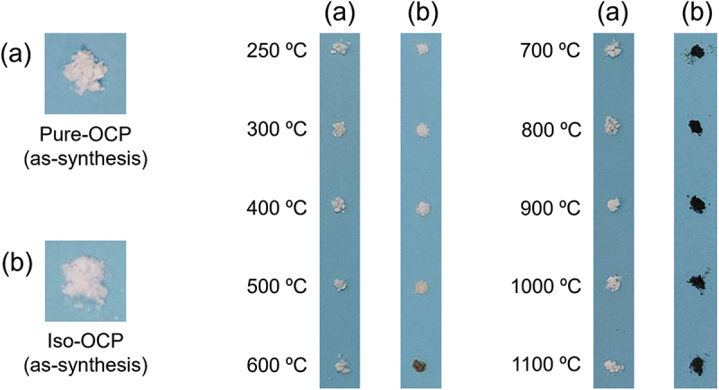
Images of (a) Pure-OCP and (b) Iso-OCP before and after heat treatment under nitrogen atmosphere.
3.2. Characterisation of sintered-body samples prepared by heat treatment of Iso-OCP compacts
3.2.1. Vickers hardness and nailing test
Table 2 lists the Vickers hardness values and results of the nailing tests of the sintered bodies prepared by the heat treatment of Iso-OCP compacts under various conditions. At the heat treatment temperature at 900°C, the Vickers hardness increased from approximately 5 to approximately 9 kgf/mm2 up to a heat treatment holding time of 24 h and remained almost constant thereafter. At the heat treatment temperature at 1000°C, samples with a heat-treatment holding time of 24 h exhibited a large Vickers hardness (11.7 kgf/mm2), whereas the other samples exhibited Vickers hardness values of approximately 8–9 kgf/mm2. For samples heat treated at 1100°C, the Vickers hardness remained almost constant up to 12 h; this value increased from approximately 10 to approximately 12 kgf/mm2 when the heat-treatment holding time was increased. Figure 3 depicts the images of representative samples that passed and failed the nailing test. As summarised in Table 2, sintered-body samples heat treated for 24 h at temperatures of 900–1100°C passed the nailing test, as well as with samples prepared by heat treatment at 900°C for 1 h.
Table 2.
Summary of the Vickers hardness and nailing test results of sintered-body samples prepared from Iso-OCP compacts based on various heat-treatment temperatures and holding times.
| Holding time (h) | Heat treatment temperature (℃) |
|||
|---|---|---|---|---|
| 900 | 1000 | 1100 | ||
| 1 | Vickers hardness (kgf/mm2) |
4.7 | 9.2 | 9.6 |
| Nailing test | Pass | Fail | Fail | |
| 12 | Vickers hardness (kgf/mm2) |
5.3 | 8.3 | 9.4 |
| Nailing test | Fail | Fail | Fail | |
| 24 | Vickers hardness (kgf/mm2) |
9.3 | 11.7 | 11.7 |
| Nailing test | Pass | Pass | Pass | |
| 48 | Vickers hardness (kgf/mm2) |
8.4 | 9.4 | 12.3 |
| Nailing test | Fail | Fail | Fail | |
The Vickers hardness values are averaged over five samples.
Figure 3.

Images of sintered-body samples prepared from Iso-OCP compacts after the nailing test. (a) success case (heat treatment condition: 1000°C, 24 h) and (b) failure case (heat treatment condition: 1000°C, 48 h).
The data in Table 2 indicate that no clear correlation exists between the Vickers hardness values and nailing test results. The sample with the lowest Vickers hardness passed the nailing test (900°C, 1 h), whereas the sample with the highest Vickers hardness failed the nailing test (1100°C, 48 h). To elucidate this phenomenon, relationships between the progress of sample sintering, diffusion of carbon components and formation of mortar layers in samples, and evaporation (loss) of char (pyrolysis products of isophthalic acid) must be investigated in detail. Because these are key factors in the design of damage-tolerant materials, their in-depth analyses are necessary.
Because the objective of this study was to develop artificial bones with improved damage tolerance, a heat-treatment holding time of 24 h was selected for further experimentation, as summarised in Table 2. Typically, materials with a high Vickers hardness value exhibit high strength. This mandates a heat-treatment temperature of 1000 or 1100°C. However, the carbon content of the samples might decrease when the heat-treatment temperature is increased. Hence, a heat-treatment condition of 1000°C for 24 h was finally selected and used for further experimentation.
3.2.2. Carbon content and chemical structures of samples
As depicted in Figure 3(a), sintered-body samples prepared from Iso-OCP compacts (heat treatment condition: 1000°C for 24 h) were black owing to char formation due to the pyrolysis of isophthalic acid. The carbon content of these samples was 2.2 mass% based on the CHN analysis. The Raman spectra of isophthalic acid and sintered samples are depicted in Figure 4. The Raman peaks derived from isophthalic acid are sharp (Figure 4(a)); their detailed vibration modes have been reported in a previous study [47]. Characteristic strong peaks were detected at 761 and 1002 cm−1, which could be attributed to the carboxy groups and aromatic rings in the sample, respectively. These strong and sharp peaks were not observed in the Raman spectrum of the sintered-body sample prepared from Iso-OCP compacts, which exhibited only two peaks derived from the char (Figure 4(b)). The first peak at approximately 1300 cm−1 was derived from the sp3 bond, whereas the second Raman peak at approximately 1590 cm−1 was derived from the sp2 bond. These Raman peaks are representative of pyrolytic carbon [48,49]. Thus, the isophthalate ions incorporated into OCP were decomposed by the heat treatment (at 1000°C for 24 h under nitrogen atmosphere) into pyrolytic carbon.
Figure 4.

Raman spectra of (a) isophthalic acid and (b) sintered-body sample prepared from Iso-OCP compacts (heat treatment condition: 1000°C, 24 h).
3.3. Comparison of properties of sintered-body samples
3.3.1. Crystalline phases
The XRD patterns of the HAp-sintered body and sintered-body samples prepared from Pure- and Iso-OCP compacts are depicted in Figure 5. The crystalline phase of the HAp-sintered body was confirmed to be single-phase HAp, whereas the crystalline phases of the sintered-body samples prepared from Pure-OCP compacts were β-TCP and β-CPP and those of the sintered-body samples prepared from Iso-OCP compacts were HAp and β-TCP. The crystalline phases of the sintered-body samples prepared from Pure- and Iso-OCP compacts were the same as those of the heat-treated Pure- and Iso-OCP powder samples (Figure 1). Moreover, the sintered-body samples prepared from Iso-OCP compacts contained pyrolytic carbon (Figure 4), confirming them to be HAp/β-TCP/pyrolytic carbon composites.
Figure 5.

XRD patterns of (a) HAp-sintered body; sintered-body samples prepared from (b) Pure-OCP and (c) Iso-OCP compacts. All samples were heat treated at 1000°C for 24 h.
3.3.2. Microstructure
The cross-sectional images of the HAp-sintered body and sintered-body samples prepared from Pure- and Iso-OCP compacts are depicted in Figure 6. Small particles (100–200 nm in diameter) were observed in the HAp-sintered body (Figure 6(a)); these particles were not significantly sintered. Numerous pores (approximately 1 μm in size) and agglomerates of particles (several micrometres in size) (Figure 6(b)) existed in the sintered-body samples prepared from Pure-OCP compacts. Interestingly, a specific cross-sectional structure (a brick-and-mortar-type structure), with plate-shaped particles oriented and stacked in the horizontal direction (perpendicular to the pressing direction), was observed for the sintered-body samples prepared from Iso-OCP compacts (Figure 6(c)). A cross-sectional SEM image of the nacreous layer of the abalone is depicted in Figure 6(d); the specific structure of the sintered-body sample prepared from Iso-OCP compact was similar to that of the nacreous layer. Notably, sintering did not appear to progress significantly in the sintered-body sample prepared from Iso-OCP compacts, as indicated by gaps between the plate-shaped particles (observed in the high-magnification SEM image; Figure 6(c)). The mortar part of the brick-and-mortar-type structure was expected to be formed by carbon components ejected from the brick part (which were originally Iso-OCP crystals); however, this could not be confirmed by SEM. To confirm this phenomenon, it is essential to observe the grain boundary area under high magnification using a transmission electron microscope.
Figure 6.

Cross-sectional SEM images of (a) HAp-sintered body; sintered-body samples prepared from (b) Pure-OCP and (c) Iso-OCP compacts; and (d) nacreous layer of natural abalone. Samples (a), (b), and (c) were heat treated at 1000°C for 24 h.
Because pores were observed in the sintered-body samples (as shown in Figure 6), the porosity of the samples was measured. The true densities of heat-treated HAp, Pure-OCP, and Iso-OCP powders in nitrogen atmosphere at 1000°C for 24 h evaluated using a helium pycnometer were 3.19, 3.12, and 3.08 g/cm3, respectively. The bulk densities of the sintered-body samples prepared from HAp, Pure-OCP, and Iso-OCP compacts were 2.02, 1.64, and 1.40 g/cm3, respectively. Hence, the porosities of the sintered-body samples prepared from HAp, Pure-OCP, and Iso-OCP compacts were 48, 47, and 55%, respectively. Therefore, the porosities of these three samples can be considered to be of the same level.
3.3.3. Mechanical properties
The representative stress – strain curves obtained from the three-point bending test of the HAp-sintered body and sintered-body samples prepared from Pure- and Iso-OCP compacts are depicted in Figure 7. Comparing with these three samples, the sintered-body samples prepared from Iso-OCP compacts exhibited the lowest bending strength, highest bending strain, and lowest Young’s modulus.
Figure 7.

Representative stress – strain curves of (a) HAp-sintered body; sintered-body samples prepared from (b) Pure-OCP and (c) Iso-OCP compacts. All samples were heat treated at 1000°C for 24 h.
Table 3 lists a comparison of the maximum bending stress, maximum bending strain, Young’s modulus, and Vickers hardness values of the HAp-sintered body and sintered-body samples prepared from Pure- and Iso-OCP compacts with those of the cortical bone [50,51]. The maximum bending stresses of the HAp-sintered body and sintered-body samples prepared from Pure- and Iso-OCP compacts were 39.1, 18.6, and 11.7 MPa, respectively. Their respective maximum bending strains were 2.2 × 10‒2, 2.3 × 10‒2, and 2.8 × 10‒2; Young’s moduli were 26.0, 12.0, and 5.3 GPa; and Vickers hardness values were 126.6, 28.4, and 11.7 kgf/mm2. The flexural strength of the obtained samples was lower than that of the cortical bone. Young’s modulus of the obtained samples was close to that of the cortical bone. The Vickers hardness of the HAp-sintered body was higher than that of the cortical bone, whereas the Vickers hardness of sintered-body samples prepared from Pure- and Iso-OCP compacts was almost the same as that of the cortical bone.
Table 3.
Comparison of maximum bending stress, maximum bending strain, Young’s modulus, and Vickers hardness values of sintered-body samples prepared from Iso-OCP, Pure-OCP, and HAp compacts with those of cortical bone. All the sintered-body samples were heat treated at 1000°C for 24 h.
| Properties of sintered-body sample | Starting material used for sintered-body sample |
Cortical bone | ||
|---|---|---|---|---|
| Iso-OCP | Pure-OCP | HAp | ||
| Maximum bending stress (MPa) | 11.7 | 18.6 | 39.1 | 166 [50] |
| Maximum bending strain (×10−2) | 2.8 | 2.3 | 2.2 | No data |
| Young’s modulus (GPa) | 5.3 | 12.0 | 26.0 | 10.8 [50] |
| Vickers hardness (kgf/mm2) | 11.7 | 28.4 | 126.6 | 34.1 [51] |
The maximum bending stress, maximum bending strain, Young’s modulus, and Vickers hardness values are averaged over five samples.
The porosity of the sintered body sample prepared from Iso-OCP was slightly higher than that of the HAp sintered body and the sintered body sample prepared from Pure-OCP. However, the porosity of these samples can be considered to be of almost the same level. Hence, although the bending strength, Young’s modulus, and Vickers hardness values of samples decreased in the following order: HAp-sintered body > sintered-body samples prepared from Pure-OCP compacts > sintered-body samples prepared from Iso-OCP compacts, explaining the cause of this mechanical-property change in terms of only the porosity. Material factors other than porosity, such as microstructure, are likely dominate these mechanical properties.
The appearances of the HAp-sintered body and sintered-body samples prepared from Pure- and Iso-OCP compacts after the nailing test are depicted in Figure 8. After the nailing test, the first two types of samples exhibited brittle fractures, whereas the nail-penetrated sintered-body samples prepared from Iso-OCP compacts did not show any fracture. Therefore, among the three types of samples tested, sintered-body samples prepared from Iso-OCP compacts exhibited the highest damage tolerance.
Figure 8.

Post-nailing-test images: (a) HAp-sintered body; sintered-body samples prepared from (b) Pure-OCP and (c) Iso-OCP compacts. All samples were heat treated at 1000°C for 24 h.
As for the relationship between sample porosity and damage tolerance, a previous study reported that alumina bulk materials with a high porosity (79.5%) do not break during the nailing test [45]. However, the porosity of the sintered-body samples prepared from Iso-OCP compacts was significantly lower (55%). Although the sintered-body samples prepared from Iso-OCP compacts with a porosity of 55% did not exhibit brittle fracture during the nailing test, the HAp sintered body with a porosity of 48% and the sintered-body samples prepared from Pure-OCP compacts with a porosity of 47% exhibited brittle fracture. The porosity of these three samples can be regarded as almost same level. Therefore, porosity is an important factor that affects the damage-tolerance property of a material. However, in this study, mechanical properties and microstructures of materials, rather than their porosity, dominated their damage-tolerance properties.
The mechanical-property characterisation results indicated that materials with a high maximum strain and low Young’s modulus exhibited a high damage tolerance, whereas those with high strength and hardness exhibited a low damage tolerance. Therefore, to design less-fragile materials, the fundamental guideline of material design is to increase material strength, resulting in high hardness and density; however, this strategy is not always appropriate for brittle materials. Materials with high damage tolerance must be designed to deform easily and tolerate large deformations. The high damage tolerance of the HAp/β-TCP/pyrolytic carbon composite obtained in this study could be attributed to its low Young’s modulus and high fracture strain owing to its moderate porosity and soft mortar part (which is likely pyrolytic carbon) of its brick-and-mortar structure. The development of materials inspired by the nacreous layer has been described in the introduction section. Damage-tolerant calcium phosphate-based materials exhibit high potential as biomaterials, especially artificial bones. The development of such bioinspired-design materials represents an important achievement in the field of ceramic biomaterials.
3.3.4. Apatite-forming abilities
Figure 9(a–c) depict the SEM images of sintered-body samples prepared from Iso-OCP compacts before and after soaking them in SBF. Before soaking in SBF, the sample exhibited a rough surface (Figure 9(a)); after soaking in SBF for 1 d, the surface of the sample was fully covered by many petal-like precipitates, several micrometres in size (Figure 9(b)). The surface morphology of the sample changed completely after soaking in SBF for 3 d (Figure 9(c)). The morphology of the precipitate formed (Figure 9(c)) is similar to that of the bone-like apatite layer formed on samples soaked in SBF [52–54]. Therefore, the layer formed on soaking the sintered-body samples prepared from Iso-OCP compacts in SBF likely comprises bone-like apatite.
Figure 9.

SEM images of sintered-body samples prepared from Iso-OCP compact: (a) before soaking in SBF, (b) after soaking in SBF for 1 d, and (c) after soaking in SBF for 3 d. (d) cross-section of the sample soaked in SBF for 3 d. (e) and (f) show EDS spectra of spots (1) and (2) shown in SEM image (d), respectively. The sample was heat treated at 1000°C for 24 h.
Figure 9(d) depicts a cross-sectional SEM image of a sintered-body sample prepared from Iso-OCP compacts after soaking it in SBF for 3 d. Figure 9(e,f) depict the EDS spectra of the precipitate layer (spot (1) in Figure 9(d)) and the sintered-body sample (spot (2) in Figure 9(d)). The cross-sectional image indicates a dense precipitate layer with a thickness of 3 μm and Ca/P molar ratio of 1.67 (calculated from the EDS spectrum depicted in Figure 9(e)). The sintered-body samples prepared from Iso-OCP compacts exhibited a porous structure before soaking them in SBF (Figure 6(c)). The porous structure was maintained after soaking in SBF for 3 d. The Ca/P molar ratio of the sintered-body part was 1.40, as indicated by the EDS spectrum (Figure 9(f)). Spots (1) and (2) show different Ca/P molar ratios, indicating the absence of a dense layer on the sintered-body sample before soaking in SBF; therefore, this layer is formed during the soaking process. The Ca/P ratio of spot (1) is similar to that of apatite (which exhibits a stoichiometric Ca/P molar ratio of 1.67), indicating that the dense layer likely consists of apatite. The aforementioned morphological and compositional analyses suggest that the sintered-body samples prepared from Iso-OCP compacts exhibit apatite-forming ability and could enable direct bone bonding in vivo.
4. Conclusions
This paper described the fabrication of calcium phosphate-based materials for artificial bones based on a bioinspired material design. Furthermore, it presented analyses of their crystalline phases, microstructures, compositions, mechanical properties, and apatite-forming abilities. Calcium phosphate-based materials were prepared by heat treating Iso-OCP compacts under a nitrogen atmosphere. Isophthalate ions incorporated into OCP decomposed at 600°C, whereas Iso-OCP decomposed to HAp and β-TCP at higher temperatures with sintering. Sintered-body samples prepared from Iso-OCP compacts (1000°C, 24 h) were HAp/β-TCP/pyrolytic carbon composites with a brick-and-mortar-type structure, similar to the nacreous layer. The maximum bending stress, maximum bending strain, Young’s modulus, and Vickers hardness values of this material were 11.7 MPa, 2.8 × 10‒2, 5.3 GPa, and 11.7 kgf/mm2, respectively. The proposed material exhibited excellent damage tolerance, sufficient to pass the nailing test, possibly because of its low Young’s modulus and high fracture strain (because of its unique microstructure). Additionally, the apatite-forming ability of the material was confirmed by in vitro testing in SBF. In summary, this study proposed a bioinspired material design for the fabrication of artificial bones with high damage tolerance for their prolonged in vivo deployment.
Acknowledgments
The authors thank Ms. Yuriko Sakamaki at the Research Core Center of TMDU for help with SEM observations.
Funding Statement
This work was partially supported by JSPS KAKENHI [Grant Nos 22H03948, 22H04500, and 22K19911] and the Institute of Biomaterials and Bioengineering, Tokyo Medical and Dental University [Project ‘Design & Engineering by Joint Inverse Innovation for Materials Architecture’] of the Ministry of Education, Culture, Sports, Science, and Technology (MEXT), Japan. This work was also supported by the Research Program for the CORE lab of the Dynamic Alliance for Open Innovation Bridging Human, Environment, and Materials, under the ‘Network Joint Research Center for Materials and Devices’.
Disclosure statement
No potential conflict of interest was reported by the author(s).
References
- [1].Demetriou MD, Launey ME, Garrett G, et al. A damage-tolerant glass. Nat Mater. 2011;10(2):123–14. doi: 10.1038/nmat2930 [DOI] [PubMed] [Google Scholar]
- [2].Ritchie RO. The conflicts between strength and toughness. Nat Mater. 2011;10(11):817–822. doi: 10.1038/nmat3115 [DOI] [PubMed] [Google Scholar]
- [3].Schlacher J, Chlup Z, Hofer AK, et al. High-temperature fracture behaviour of layered alumina ceramics with textured microstructure. J Eur Ceram Soc. 2023;43(7):2917–2927. doi: 10.1016/j.jeurceramsoc.2022.11.046 [DOI] [Google Scholar]
- [4].Schlacher J, Jabr A, Hofer AK, et al. Contact damage tolerance of alumina-based layered ceramics with tailored microstructures. J Am Ceram Soc. 2022;105(6):4387–4399. doi: 10.1111/jace.18389 [DOI] [PMC free article] [PubMed] [Google Scholar]
- [5].Wang Y, Liu Q, Zhang B, et al. High damage-tolerance bio-inspired B4C/2024Al composites with adjustable mechanical performance by tuning ceramic thickness. Mater Sci Eng A. 2021;819:141469. doi: 10.1016/j.msea.2021.141469 [DOI] [Google Scholar]
- [6].Zhao G, Chen J, Li Y, et al. YB2C2: a machinable layered ternary ceramic with excellent damage tolerance. Scr Mater. 2016;124:86–89. doi: 10.1016/j.scriptamat.2016.06.041 [DOI] [Google Scholar]
- [7].Wang X, Xiang H, Sun X, et al. Mechanical properties and damage tolerance of bulk Yb3Al5O12 ceramic. J Mater Sci Technol. 2015;31(4):369–374. doi: 10.1016/j.jmst.2015.01.002 [DOI] [Google Scholar]
- [8].Coldea A, Swain MV, Thiel N.. Hertzian contact response and damage tolerance of dental ceramics. J Mech Behav Biomed Mater. 2014;34:124–133. doi: 10.1016/j.jmbbm.2014.02.002 [DOI] [PubMed] [Google Scholar]
- [9].Zhang Y, Pajares A, Lawn BR. Fatigue and damage tolerance of Y-TZP ceramics in layered biomechanical systems. J Biomed Mater Res, Part B. 2004;71B(1):166–171. doi: 10.1002/jbm.b.30083 [DOI] [PubMed] [Google Scholar]
- [10].Hench LL. Bioceramics: from concept to clinic. J Am Ceram Soc. 1991;74(7):1487–1510. doi: 10.1111/j.1151-2916.1991.tb07132.x [DOI] [Google Scholar]
- [11].Kokubo T. Bioactive glass ceramics: properties and applications. Biomaterials. 1991;12(2):155–163. doi: 10.1016/0142-9612(91)90194-F [DOI] [PubMed] [Google Scholar]
- [12].Holand W, Gotz W, Carl G, et al. Microstructure of mica glass-ceramics and interface reactions between mica glass-ceramics and bone. Cells Mat. 1992;2(2):105–112. [Google Scholar]
- [13].Lee S, Shiraki S, Nagata F, et al. Structure and dissolution behavior of boron-containing calcium phosphate invert glasses. J Non-Cryst Solids. 2022;590:121690. doi: 10.1016/j.jnoncrysol.2022.121690 [DOI] [Google Scholar]
- [14].Obata A, Lee S, Kasuga T. Bioactive glass materials for tissue regeneration. J Ceram Soc Jpn. 2022;130(8):595–604. doi: 10.2109/jcersj2.22054 [DOI] [Google Scholar]
- [15].Lee S, Nagata F, Kato K, et al. Structures and dissolution behaviors of quaternary CaO-SrO-P2O5-TiO2 glasses. Materials. 2021;14(7):1736. doi: 10.3390/ma14071736 [DOI] [PMC free article] [PubMed] [Google Scholar]
- [16].Izzetti R, Gennai S, Nisi M, et al. Clinical applications of nano-hydroxyapatite in dentistry. Appl Sci. 2022;12(21):10762. doi: 10.3390/app122110762 [DOI] [Google Scholar]
- [17].Funayama T, Noguchi H, Kumagai H, et al. Unidirectional porous beta-tricalcium phosphate and hydroxyapatite artificial bone: a review of experimental evaluations and clinical applications. J Artif Organs. 2021;24(2):103–110. doi: 10.1007/s10047-021-01270-8 [DOI] [PMC free article] [PubMed] [Google Scholar]
- [18].Miura K, Sumita Y, Kajii F, et al. First clinical application of octacalcium phosphate collagen composite on bone regeneration in maxillary sinus floor augmentation: a prospective, single-arm, open-label clinical trial. J Biomed Mater Res Part B. 2020;108(1):243–252. doi: 10.1002/jbm.b.34384 [DOI] [PubMed] [Google Scholar]
- [19].Kawai T, Echigo S, Matsui K, et al. First clinical application of octacalcium phosphate collagen composite in human bone defect. Tissue Eng Part A. 2014;20(7–8):1336–1341. doi: 10.1089/ten.tea.2013.0508 [DOI] [PMC free article] [PubMed] [Google Scholar]
- [20].Ghazlan A, Ngo T, Tan P, et al. Inspiration from nature’s body armours - a review of biological and bioinspired composites. Compos Part B. 2021;205:108513. doi: 10.1016/j.compositesb.2020.108513 [DOI] [Google Scholar]
- [21].Amorim L, Santos A, Nunes JP, et al. Bioinspired approaches for toughening of fibre reinforced polymer composites. Mater Des. 2021;199:109336. doi: 10.1016/j.matdes.2020.109336 [DOI] [Google Scholar]
- [22].Wang Y, Naleway SE, Wang B. Biological and bioinspired materials: structure leading to functional and mechanical performance. Bioact Mater. 2020;5(4):745–757. doi: 10.1016/j.bioactmat.2020.06.003 [DOI] [PMC free article] [PubMed] [Google Scholar]
- [23].Wang Y, Liu Q, Zhang B, et al. Bioinspired nacre-like 2024Al/B4C composites with high damage tolerance. Ceram Int. 2022;48(18):26326–26334. doi: 10.1016/j.ceramint.2022.05.316 [DOI] [Google Scholar]
- [24].Wan H, Leung N, Jargalsaikhan U, et al. Fabrication and characterisation of alumina/aluminium composite materials with a nacre-like micro-layered architecture. Mater Des. 2022;223:111190. doi: 10.1016/j.matdes.2022.111190 [DOI] [Google Scholar]
- [25].Li YL, Guo RF, Hu ZJ, et al. Construction of nacre-mimetic composites with a “brick-and-mortar” architecture based on structural defects in ice-templating. Mater Des. 2021;204:109668. doi: 10.1016/j.matdes.2021.109668 [DOI] [Google Scholar]
- [26].Wilkerson RP, Gludovatz B, Ell J, et al. High-temperature damage-tolerance of coextruded, bioinspired (“nacre-like”), alumina/nickel compliant-phase ceramics. Scr Mater. 2019;158:110–115. doi: 10.1016/j.scriptamat.2018.08.046 [DOI] [Google Scholar]
- [27].Wat A, Lee JI, Ryu CW, et al. Bioinspired nacre-like alumina with a bulk-metallic glass-forming alloy as a compliant phase. Nat Commun. 2019;10(1):961. doi: 10.1038/s41467-019-08753-6 [DOI] [PMC free article] [PubMed] [Google Scholar]
- [28].Mathew M, Brown WE, Schroeder LW, et al. Crystal structure of octacalcium bis (hydrogenphosphate) tetrakis (phosphate) pentahydrate, Ca8(HPO4)2(PO4)4·5H2O. J Crystallogr Spectrosc Res. 1988;18(3):235–250. doi: 10.1007/BF01194315 [DOI] [Google Scholar]
- [29].Brown WE, Smith JP, Lehr JR, et al. Octacalcium phosphate and hydroxyapatite: crystallographic and chemical relations between octacalcium phosphate and hydroxyapatite. Nature. 1962;196(4859):1050–1055. doi: 10.1038/1961050a0 [DOI] [Google Scholar]
- [30].Brown WE, Lehr JR, Smith JP, et al. Crystallography of octacalcium phosphate. J Am Chem Soc. 1957;79(19):5318–5319. doi: 10.1021/ja01576a068 [DOI] [Google Scholar]
- [31].Yokoi T, Shimabukuro M, Kawashita M. Octacalcium phosphate with incorporated carboxylate ions: a review. Sci Technol Adv Mater. 2022;23(1):434–445. doi: 10.1080/14686996.2022.2094728 [DOI] [PMC free article] [PubMed] [Google Scholar]
- [32].Mathew M, Brown W. A structural model for octacalcium phosphate-succinate double salt. Bull Chem Soc Jpn. 1987;60(3):1141–1143. doi: 10.1246/bcsj.60.1141 [DOI] [Google Scholar]
- [33].Monma H, Goto M. Thermal alteration of succinate-complexed octacalcium phosphate. J Mater Sci Lett. 1985;4(2):147–150. doi: 10.1007/BF00728061 [DOI] [Google Scholar]
- [34].Monma H, Goto M. Complexes of apatitic layered compound Ca8(HPO4)2(PO4)4·5H2O with dicarboxylates. J Inclusion Phenom. 1984;2(1):127–134. doi: 10.1007/BF00663248 [DOI] [Google Scholar]
- [35].Monma H. The incorporation of dicarboxylates into octacalcium bis(hydrogenphosphate) tetrakis(phosphate) pentahydrate. Bull Chem Soc Jpn. 1984;57(2):599–600. doi: 10.1246/bcsj.57.599 [DOI] [Google Scholar]
- [36].Monma H, Goto M. Succinate-complexed octacalcium phosphate. Bull Chem Soc Jpn. 1983;56(12):3843–3844. doi: 10.1246/bcsj.56.3843 [DOI] [Google Scholar]
- [37].Yokoi T, Watanabe M, Goto T, et al. Synthesis of octacalcium phosphate containing glutarate ions with a high incorporation fraction. Materials. 2023;16(1):64. doi: 10.3390/ma16010064 [DOI] [PMC free article] [PubMed] [Google Scholar]
- [38].Yokoi T, Goto T, Kato T, et al. Hydroxyapatite formation from octacalcium phosphate and its related compounds: a discussion of the transformation mechanism. Bull Chem Soc Jpn. 2020;93(5):701–707. doi: 10.1246/bcsj.20200031 [DOI] [Google Scholar]
- [39].Yokoi T, Goto T, Kitaoka S. Formation of hydroxyapatite crystals from octacalcium phosphate with incorporated succinate ion under hydrothermal conditions. Chem Lett. 2019;48(8):855–858. doi: 10.1246/cl.190258 [DOI] [Google Scholar]
- [40].Yokoi T, Goto T, Sekino T, et al. Fluorescent properties of octacalcium phosphate with incorporated isophthalate ions. J Ceram Soc Jpn. 2022;130(5):337–340. doi: 10.2109/jcersj2.21173 [DOI] [Google Scholar]
- [41].Yokoi T, Goto T, Hara M, et al. Incorporation of tetracarboxylate ions into octacalcium phosphate for the development of next-generation biofriendly materials. Comm Chem. 2021;4(1):4. doi: 10.1038/s42004-020-00443-5 [DOI] [PMC free article] [PubMed] [Google Scholar]
- [42].Yamada I, Tagaya M. Immobilization of 2,2′-bipyridine-5,5′-dicarboxylic acid in layered octacalcium phosphate. Colloid Interface Sci Commun. 2019;30:100182. doi: 10.1016/j.colcom.2019.100182 [DOI] [Google Scholar]
- [43].Kamitakahara M, Okano H, Tanihara M, et al. Synthesis of octacalcium phosphate intercalated with dicarboxylate ions from calcium carbonate and phosphoric acid. J Ceram Soc Jpn. 2008;116(1351):481–485. doi: 10.2109/jcersj2.116.481 [DOI] [Google Scholar]
- [44].Nakahira A, Aoki S, Sakamoto K, et al. Synthesis and evaluation of various layered octacalcium phosphates by wet-chemical processing. J Mater Sci Mater Med. 2001;12(9):793–800. doi: 10.1023/A:1017968818168 [DOI] [PubMed] [Google Scholar]
- [45].Tallon C, Chuanuwatanakul C, Dunstan DE, et al. Mechanical strength and damage tolerance of highly porous alumina ceramics produced from sintered particle stabilized foams. Ceram Int. 2016;42(7):8478–8487. doi: 10.1016/j.ceramint.2016.02.069 [DOI] [Google Scholar]
- [46].Monma H. Thermal properties of layer-structured calcium phosphate intercalated with succinate and methylsuccinate ions. Gypsum Lime. 1990;1990(229):396–401. [Google Scholar]
- [47].Bardak F, Karaca C, Bilgili S, et al. Conformational, electronic, and spectroscopic characterization of isophthalic acid (monomer and dimer structures) experimentally and by DFT. Spectroc Acta Part A. 2016;165:33–46. doi: 10.1016/j.saa.2016.03.050 [DOI] [PubMed] [Google Scholar]
- [48].McEvoy N, Peltekis N, Kumar S, et al. Synthesis and analysis of thin conducting pyrolytic carbon films. Carbon. 2012;50(3):1216–1226. doi: 10.1016/j.carbon.2011.10.036 [DOI] [Google Scholar]
- [49].Jie C, Xiang X, Peng X. The effect of carbon nanotube growing on carbon fibers on the microstructure of the pyrolytic carbon and the thermal conductivity of carbon/carbon composites. Mater Chem Phys. 2009;116(1):57–61. doi: 10.1016/j.matchemphys.2009.02.044 [DOI] [Google Scholar]
- [50].Yin B, Guo J, Wang J, et al. Bone material properties of human phalanges using Vickers indentation. Orthop Surg. 2019;11(3):487–492. doi: 10.1111/os.12455 [DOI] [PMC free article] [PubMed] [Google Scholar]
- [51].Nyman JS, Roy A, Shen XM, et al. The influence of water removal on the strength and toughness of cortical bone. J Biomech. 2006;39(5):931–938. doi: 10.1016/j.jbiomech.2005.01.012 [DOI] [PMC free article] [PubMed] [Google Scholar]
- [52].Ohtsuki C, Kamitakahara M, Miyazaki T. Coating bone-like apatite onto organic substrates using solutions mimicking body fluid. J Tissue Eng Regen Med. 2007;1(1):33–38. doi: 10.1002/term.3 [DOI] [PubMed] [Google Scholar]
- [53].Miyazaki T, Kim HM, Kokubo T, et al. Mechanism of bonelike apatite formation on bioactive tantalum metal in a simulated body fluid. Biomaterials. 2002;23(3):827–832. doi: 10.1016/S0142-9612(01)00188-0 [DOI] [PubMed] [Google Scholar]
- [54].Li P, Ohtsuki C, Kokubo T, et al. Process of formation of bone-like apatite layer on silica-gel. J Mater Sci Mater Med. 1993;4(2):127–131. doi: 10.1007/BF00120381 [DOI] [Google Scholar]