Abstract
Objectives
To clarify the effect of attachment types on bodily movement of the maxillary canine in aligner orthodontics.
Materials and Methods
Using an aligner, the canine was moved bodily by 0.1 mm distally as a target position. Orthodontic tooth movement was simulated using the finite element method (FEM). The alveolar socket was displaced in the same manner as the initial movement caused by elastic deformation of the periodontal ligament. First, the initial movement was calculated, and then the alveolar socket was displaced in the same direction and with the same magnitude as the initial movement. These calculations were repeated to move the teeth after placement of the aligner. The teeth and the alveolar bone were assumed to be rigid bodies. A FEM model of the aligner was made based on the crown surfaces. The thickness of the aligner was 0.45 mm, and its Young’s modulus was 2 GPa. Three types of attachments—semicircular couple, vertical rectangular, and horizontal rectangular—were placed on the canine crown.
Results
Regardless of the type of attachment, upon placement of the aligner on the dentition the crown of the canine moved to the target position, while the apex hardly moved. That is, the canine tipped and rotated. After repeating the calculation, the canine became upright and moved bodily regardless of the attachment type. In the aligner without an attachment, the canine did not become upright.
Conclusions
There was almost no difference among attachment types in terms of achieving bodily movement of the canine.
Keywords: Orthodontics, Aligner, Attachment, Bodily movement, Finite element method
INTRODUCTION
Transparent aligner treatment has esthetic advantages over conventional wire-bracket treatment. Various types of tooth movement may be achieved by the aligner. Kravitz et al.1,2 evaluated the accuracy of tooth movement in labial expansion, lingual constriction, intrusion, extrusion, mesiodistal tip, labiolingual tip, and rotation of the anterior teeth and reported a mean accuracy of 41%, where the accuracy was the ratio of the achieved to predicted tooth movement; the accuracy is 100% when the tooth moves completely to the predicted position. Krieger et al.3 reported that tooth corrections in the vertical plane were difficult to realize, but anterior crowding was successfully corrected. In a recent clinical study by Simon et al.,4 the accuracies for bodily movements such as incisor torque, premolar derotation, and molar distalization were measured as 42%, 40%, and 87%, respectively. They concluded that bodily tooth movements could be accomplished using aligners.4
Attachments have been used to create an appropriate force system for the desired movement using aligners. Depending on the movement types, various attachments have been devised.5 However, the effects of each attachment have not been fully clarified from the mechanical point of view.
Previously, many finite element method (FEM) studies6–14 were carried out to examine the effects of attachments. Most only evaluated initial movement at the placement of an aligner on the dentition. In addition, there were few studies6,12 in which long-term orthodontic tooth movements were simulated.
In a previous FEM study12 in which long-term movements were simulated in the closing of a diastema, the movement pattern of the central incisor varied as the teeth moved. That is, the central incisor tipped in the initial movement but could move bodily after a long time. To evaluate the effect of attachments, long-term orthodontic tooth movement should be simulated.
In a previous study,12 it was found that the central incisor could move bodily with the semicircular couple attachment. However, the study did not clarify whether other attachments have the same effect as the semicircular couple attachment. In the present study, using the same FEM as in the previous article12 the aim was to investigate how the types of attachment affected bodily tooth movement.
MATERIALS AND METHODS
Simulation of Orthodontic Tooth Movement
Applying a force on a tooth causes it to move through an elastic deformation of the periodontal ligament (PDL), which is called the “initial tooth movement.” When maintaining the force, resorption and apposition of the alveolar bone occur at the compression and retraction area in the PDL. As a result of bone remodeling, the alveolar socket is displaced, through which action the tooth moves, and this is orthodontic tooth movement. By using the FEM, displacement of the alveolar socket was simulated. It was assumed that the alveolar socket would move in the same direction as the initial tooth movement.12,15,16
Figure 1 shows the calculation procedure for simulating orthodontic tooth movement12,15 which consisted of three steps. First, an aligner was placed on the dentition. Second, the initial movements of the teeth were calculated. Third, the alveolar sockets were moved in the same direction and with the same magnitude as those in the initial movements. Repeating the second and third steps, the teeth moved with their alveolar sockets. Forces acting on the dentition were updated as the teeth moved. The number of repeating calculations, N, was a parameter representing an elapsed time, but the N could not be converted to real time.
Figure 1.
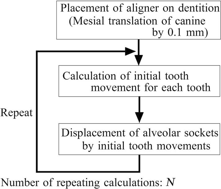
Repeating calculation for simulating orthodontic tooth movement.
Finite Element Model
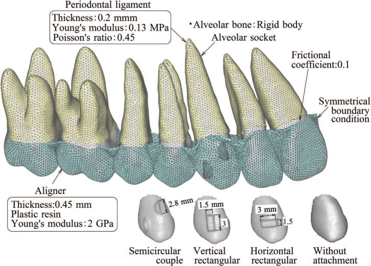
Figure 2 shows the FEM model in which an aligner was placed on the maxillary dentition having the target tooth positions. The FEM software ANSYS19.1 (ANSYS Inc, Canonsburg, Pa) was used. Assuming bilateral symmetry, only the right side was modeled, and the symmetric boundary condition was applied to the midsection of the aligner. In the calculation of the initial movement, because the elastic deformations of the alveolar bone and teeth were negligible compared to that of the PDL, the alveolar bone and teeth were assumed to be rigid bodies.12,16 In the simulation of orthodontic movement (Figure 1), the alveolar socket was moved by displacing the nodes on the outer surface of the PDL; therefore, the alveolar bone was no longer needed for the simulation and was excluded from the FEM model.
Figure 2.
Finite element model.
Three-dimensional models of the teeth were constructed based on a dental study model (i21D-400C, Nissin Dental Products Inc, Kyoto, Japan). The surface of each tooth was divided into three-dimensional thin shell elements, and their nodes were constrained to make the tooth rigid. The PDL having 0.2-mm thickness was made by extruding the root elements. The PDL was assumed to be a linear elastic material, the Young’s modulus and Poisson’s ratio of which were 0.13 MPa and 0.45, respectively.15 These elastic moduli were determined so that the in vivo initial movement of the upper first premolar could be reproduced by the FEM.15 The total number of elements and nodes of all teeth were 34,624 and 67,210, respectively.
A FEM model of the aligner was made manually by merging the adjacent regions of the crown surfaces using a polygon editor (Metasequoia 4, Tetraface Inc, Tokyo, Japan).12 Three attachments of different types5—semicircular couple, vertical rectangular, and horizontal rectangular—were placed on the canine, as shown in Figure 2. This aligner model was fitted perfectly to the crown surfaces of the target dentition. The thickness of the aligner was 0.45 mm, and its Young’s modulus was 2 GPa, which was evaluated by the bending test of an aligner material. The aligner was divided into three-dimensional shell elements, which were used for analyzing thin to moderately thick shell structures. The number of elements and nodes of the aligner were 16,417 and 79,406, respectively. The frictional coefficient between the aligner and crowns was 0.1.
The simulated case was one in which the canine was translated distally 0.1 mm by the aligner. To activate the aligner, the alveolar socket of the canine was translated mesially 0.1 mm. This process was equivalent to placing the aligner on the dentition with the mesially translated canine.
RESULTS
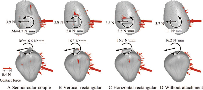
Figure 3 shows contact forces acting on the canine crown at the placement (activation) of the aligner. Distal force and moment acting on the canine at the bracket position were calculated by integrating the nodal forces on the alveolar socket. In all cases, the aligners were in contact with the mesial sides of the crowns. In the aligners with attachment, contact forces acted on the attachment also. Amounts of the distal force and the clockwise moments M2 were almost the same in all cases. The counterclockwise moment M1, which tended to prevent distal tipping of the canine, was larger in the aligner with attachment than in the one without attachment. The M1 was the largest for the semicircle attachment.
Figure 3.
Contact force acting on crown at placement (activation) of aligner. (A) Semicircular couple; (B) vertical rectangular; (C) horizontal rectangular; and (D) without attachment.
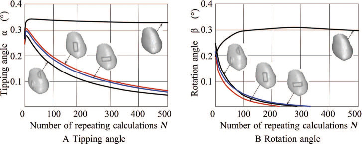
Figure 4 shows changes in the tipping and rotation angles of the canine with the number of repeating calculations, N. In all cases, at the placement of the aligner (N = 0), the crown of the canine moved almost to the target position, but its apex hardly moved. At that time, the canine tipped and rotated and did not move bodily.
Figure 4.
Changes in tipping and rotational angles with repeating calculations. (A) Tipping angle and (B) rotation angle.
When repeating the calculations, in the aligner without attachment the tipping and rotation angles did not decrease: that is, the canine still tipped and rotated. But in the aligners with attachment, the tipping and rotation angles decreased and approached 0 with an increase in N.
When repeating the calculations, the teeth moved little by little, and the initial deformation of the aligner gradually disappeared. The force acting on the teeth decreased, and the teeth hardly moved at N = 500. At that point, the effect of each attachment on the bodily movement of the canine was clarified; therefore, the repeating calculations were stopped. The point of N = 500 was regarded as a sufficiently long time after wearing the aligners in clinical settings.
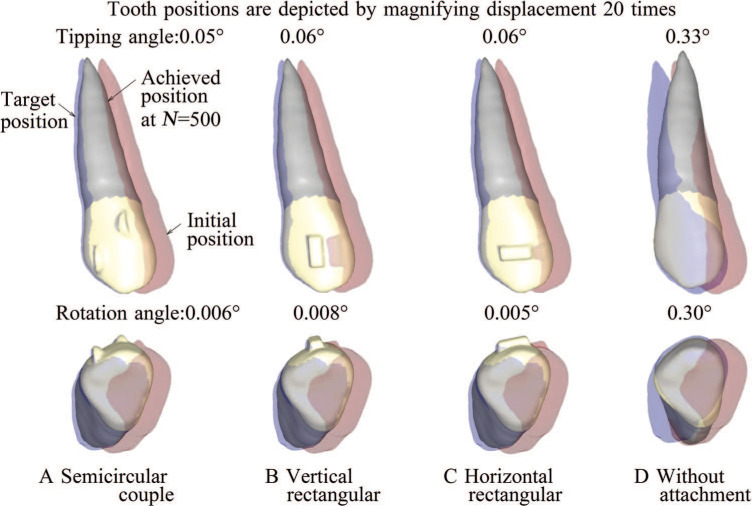
Figure 5 shows the movement patterns of the canine when repeating the calculation 500 times (N = 500). To make the movement pattern easier to understand, the movements of the canine were magnified 20 times. The teeth depicted in red and blue reflect the initial and the target positions, respectively. In the aligners with attachments, the canines moved bodily almost to the target positions. In the aligner without attachment, the crown of the canine moved to the target position, but the apex hardly moved.
Figure 5.
Movement pattern of canine when repeating calculation 500 times (N = 500). (A) Semicircular couple; (B) vertical rectangular; (C) horizontal rectangular; and (D) without attachment.
DISCUSSION
Movement Mechanics in Aligner Orthodontics
At the placement (activation) of the aligner, the canine tipped and rotated because of the elastic deformation of the aligner. At that time, the elastic energy was stored in the aligner, and elastic forces acted on the canine (Figure 3). After that, in the aligner with attachment, the forces were well transmitted to the crown; therefore, the canine became upright (Figure 4). It led to the bodily movement of the canine (Figure 5). The aligner worked in the same way as a retraction spring in conventional wire-bracket orthodontics.15
In aligner orthodontics, the elastic forces exerted in the aligner were transmitted to the crowns through the contact surfaces. Then, the attachment was effective in gripping the crown and increasing the moment, tending to upright the canine (Figure 3). On the other hand, in the aligner without attachment, the aligner slipped on the crown, and therefore the canine did not become upright. In previous FEM simulations,12 the same effectiveness of the attachments has been demonstrated in the central incisor.
In clinical settings, many aligners are placed sequentially, and the teeth are moved little by little. In the present study, the aligners with attachment were able to move the canine bodily by 0.1 mm. Therefore, if this movement is repeated using many aligners, it can be expected that the canine will move bodily over a long distance.
Effect of Attachment Type
Regardless of the attachment type, the tipping and rotation angles decreased toward 0 (Figure 4), and the canines moved bodily at N = 500 (Figure 5). In Figure 4, although the tipping and rotation angles were smallest for the semicircular couple and the vertical rectangular attachments, the differences in the effects of the three attachments were very slight and of little clinical significance. Therefore, it was concluded that the attachment types were less effective for the bodily movement of the canine. These were new findings in the present article. Either of the rectangular attachments was superior for achieving bodily movement, regardless of whether that movement was in the distal or mesial direction. There are a few reasons why the semicircular couple attachment should be selected.
Features of FEM Simulation
It is well known that orthodontic tooth movement is caused by remodeling of the alveolar bone induced by a mechanical stimulus to the PDL. However, its mechanism has not been clarified. At present, it is difficult to simulate tooth movement based on a biological bone remodeling law.
On the other hand, from a macroscopic or a phenomenological point of view, when comparing the before and after movement of the tooth, it can be understood that orthodontic tooth movement is caused by displacement of the alveolar socket; the movement pattern in orthodontic tooth movement is similar to that in the initial movement. In both movements, the tooth tips when a force is applied to the crown, and the tooth moves bodily when an appropriate moment is applied in addition to the force. An in vivo experiment17 also showed that the initial displacement was a predictor for forecasting long-term movement. Based on these insights into orthodontic movement, the present simulation method was developed by Kojima and Fukui15 and Kim et al.16 in which the tooth or the alveolar socket was displaced in the same direction as the initial movement. This method enabled simulation of long-term orthodontic movement without using the bone remodeling law.
The response to the force of one tooth is similar between the orthodontic and initial movements. However, in clinical treatments in which many teeth are constrained by wire or an aligner, the forces change with tooth movement. In the present method, the forces acting on the teeth were updated at repeating calculations,15,16 which enabled simulation of long-term tooth movements in clinical settings. In the present study, the canine first tipped and then became upright. As a result, we clarified that an attachment was necessary for bodily movement. Such changes in movement patterns were observed in wire-bracket orthodontics.15,16,18,19
With the present method, in which the alveolar socket was displaced,12,16 the tooth could be moved with the same magnitude as the initial movement. In an alternative method in which the tooth was directly moved, it should be moved only 1/1000th of the initial movement,15 which significantly increased the computational time.
Although the actual PDL has nonlinear elastic properties, it was assumed to be a linear elastic material. This simplification reduced the computational time for calculating the initial movement but had little effect on tooth movement patterns.15
Limits of FEM Simulation
In the simulation, the tooth was moved by the repeating calculation. On the other hand, in clinical settings, the tooth moves with the lapse of time. Therefore, the number of iterations was regarded to constitute the wear time of the aligner. However, because the time required for initial movement has not yet been determined, the number of iterations could not be converted into actual time. As a result, the treatment duration was unpredictable. This was the limitation of the present phenomenological simulation method.
The present FEM model of the aligner was fitted perfectly to the crown surfaces. However, in clinical settings, undesirable imperfections occur in the manufacture of the aligner.20 For example, small errors may occur while taking the dental impression, making the target dental model, and/or forming the aligner. Such imperfections of the aligner were neglected in the present study, which was a limitation of the present study. Because forces created in the aligner were transmitted by contact with the crown, imperfections of the aligner may compromise a close fit and reduce the efficacy of tooth movement. In a future study, the effect of imperfections in the aligner should be investigated.
CONCLUSIONS
The canine was moved bodily by the aligner with attachment but tipped and rotated by the aligner without attachment.
There was almost no difference among attachment types in terms of achieving bodily movement of the canine.
ACKNOWLEDGMENT
The authors thank Dr Yukio Kojima for his valuable advice and support in the finite element simulation.
REFERENCES
- 1. Kravitz ND, Kusnoto B, BeGole E, Obrez A, Agran B. How well does Invisalign work? A prospective clinical study evaluating the efficacy of tooth movement with Invisalign. Am J Orthod Dentofacial Orthop. 2009;135:27–35. doi: 10.1016/j.ajodo.2007.05.018. [DOI] [PubMed] [Google Scholar]
- 2. Kravitz ND, Kusnoto B, Agran B, Viana G. Influence of attachments and interproximal reduction on the accuracy of canine rotation with Invisalign A prospective clinical study. Angle Orthod. 2008;78:682–687. doi: 10.2319/0003-3219(2008)078[0682:IOAAIR]2.0.CO;2. [DOI] [PubMed] [Google Scholar]
- 3. Krieger E, Seiferth J, Marinello I, et al. Invisalign treatments in the anterior tooth region: were the predicted tooth movements achieved? J Orofac Orthoped. 2012;73:365–376. doi: 10.1007/s00056-012-0097-9. [DOI] [PubMed] [Google Scholar]
- 4. Simon M, Keilig L, Schwarze J, Jung BA, Bourauel C. Treatment outcome and efficacy of an aligner technique—regarding incisor torque, premolar derotation and molar distalization. BMC Oral Health. 2014;14:68–74. doi: 10.1186/1472-6831-14-68. [DOI] [PMC free article] [PubMed] [Google Scholar]
- 5. Chang MJ, Chen CH, Chang CY, Lin JSY, Chang CH, Roberts WE. Introduction to Invisalign® smart technology: attachments design, and recall-checks. J Digital Orhod. 2019;54:80–95. [Google Scholar]
- 6. Cai Y, Yang X, He B, Yao J. Finite element method analysis of the periodontal ligament in mandibular canine movement with transparent tooth correction treatment. BMC Oral Health. 2015;15:106. doi: 10.1186/s12903-015-0091-x. [DOI] [PMC free article] [PubMed] [Google Scholar]
- 7. Gomez JP, Pena FM, Martinez V, Giraldo DC, Cardona CI. Initial force systems during bodily tooth movement with plastic aligners and composite attachments: a three-dimensional finite element analysis. Angle Orthod. 2015;85:454–460. doi: 10.2319/050714-330.1. [DOI] [PMC free article] [PubMed] [Google Scholar]
- 8. Garino F, Castroflorio T, Daher S, Rossini G, Cugliari G, Deregibus A. Effectiveness of composite attachments in controlling upper-molar movement with aligner. J Clin Orthod. 2016;50:341–347. [PubMed] [Google Scholar]
- 9. Comba S, Parrini G, Rossini T, Castroflorio A, Deregibus A. Three-dimensional finite element analysis of upper-canine distalization with clear aligners, composite attachments, and Class II elastics. J Clin Orthod. 2017;51:24–28. [PubMed] [Google Scholar]
- 10. Goto M, Yanagisawa W, Kimura H, Inou N, Maki K. A method for evaluation of the effect of attachments in aligner-type orthodontic appliance: three-dimensional finite element analysis. Orthod Waves. 2017;76:207–214. [Google Scholar]
- 11. Gomez JP, Marcelo F, Valencia E, Eduardo C. Effect of composite attachment on initial force system generated during canine rotation with plastic aligners: a three-dimensional finite elements analysis. J Aligner Orthod. 2018;2:31–36. [Google Scholar]
- 12. Yokoi Y, Arai A, Kawamura J, Uozumi T, Usui Y, Okafuji N. Effects of attachment of plastic aligner in closing of diastema of maxillary dentition by finite element method J Healthcare Eng 2019. article 1075096. Available at: 10.1155/2019/1075097. [DOI] [PMC free article] [PubMed] [Google Scholar]
- 13. Saviguano R, Valentino R, Razionale AV, Michelotti A, Barone S. Biomechanical effect of different auxiliary-aligner designs for the extraction of an upper central incisor: a finite element analysis J Healthcare Eng 2019. article 9687127. Available at: 10.1155/2019/9687127. [DOI] [PMC free article] [PubMed] [Google Scholar]
- 14. Cortona A, Rossini G, Parrini S, Deregibus A, Castroflorio T. Clear aligner orthodontic therapy of rotated mandibular round-shaped teeth: a finite element study. Angle Orthod. 2019;90:247–254. doi: 10.2319/020719-86.1. [DOI] [PMC free article] [PubMed] [Google Scholar]
- 15. Kojima Y, Fukui H. Numerical simulation of canine retraction with T-loop spring based on the updated moment-to-force ratio. Eur J Orthod. 2012;34:10–18. doi: 10.1093/ejo/cjq164. [DOI] [PubMed] [Google Scholar]
- 16. Kim MJ, Park JH, Kojima Y, Tai K, Chae JM. A finite element simulation of the optimal bending angles in a running loop for mesial translation of a mandibular molar using indirect skeletal anchorage. Orthod Craniofac Res. 2018;21:63–70. doi: 10.1111/ocr.12216. [DOI] [PubMed] [Google Scholar]
- 17. Soenen PL, Dermaut LR, Verbeeck MH. Initial tooth displacement in vivo as a predictor of long-term displacement. Eur J Orthod. 1999;21:405–411. doi: 10.1093/ejo/21.4.405. [DOI] [PubMed] [Google Scholar]
- 18. Kojima Y, Fukui H. Numerical simulations of en-masse space closure with sliding mechanics. Am J Orthod Dentofacial Orthop. 2010;138:702.e1–702.e6. doi: 10.1016/j.ajodo.2010.06.015. [DOI] [PubMed] [Google Scholar]
- 19. Kojima Y, Fukui H. A finite element simulation of initial movement, orthodontic movement, and the center of resistance of the maxillary teeth connected with an archwire. Eur J Orthod. 2014;36:255–261. doi: 10.1093/ejo/cjr123. [DOI] [PubMed] [Google Scholar]
- 20. Koenig N, Choi JY, McCray JY, Hayes A, Schneider P, Kim KB. Comparison of dimensional accuracy between direct-printed and thermoformed aligners. Korean J Orthod. 2022;52:249–257. doi: 10.4041/kjod21.269. [DOI] [PMC free article] [PubMed] [Google Scholar]


