Abstract
Optical beam steering has broad applications in lidar, optical communications, optical interconnects, and spatially resolved optical sensors. For high-speed applications, phased-array-based beam-steering methods are favored over mechanical methods, as they are unconstrained by inertia and can inherently operate at a higher speed. However, phased-array systems exhibit a tradeoff between angular range and beam divergence, making it difficult to achieve both a large steering angle and a narrow beam divergence. Here, we present a beam-steering method based on wavefront shaping through a disorder-engineered metasurface that circumvents this range-resolution tradeoff. We experimentally demonstrate that, through this technique, one can continuously steer an optical beam within a range of 160° (80° from normal incidence) with an angular resolution of about 0.01° at the cost of beam throughput.
Optical beam steering has applications in lidar, optical communications, and optical interconnects [1-3]. Broadly speaking, beam steering is performed either mechanically or via a phased array. Mechanical solutions, such as decentered lenses [4], Risley prisms [5], and galvanometer-scanning mirrors [6], use reflective or deflective optics and moving optical elements to steer the light. Phased-array-based solutions typically involve the use of coherent light sources and phase modulators [7-11]. By modulating the phase of each element in the array, the emitted coherent light can be made to constructively interfere in the far field at a specified angle, thereby generating a beam in the desired direction.
The performance of beam-steering systems can be characterized by the steering angular range (θ), angular resolution (), number of resolvable beam directions (), beam throughput, and speed. For all of these benchmarks except speed, mechanical systems are on par or outperform phased arrays [12]. This is especially true for the maximum number of resolvable beam directions. The best reported number of resolvable beam directions (1D) for a mechanical method can reach to ~2.5 × 10⁵ [12], while the best reported number for a phased-array method is 500 [11]—a difference of 3 orders of magnitude. On the other hand, phased arrays hold the advantage in speed over mechanical methods. Specifically, inertia limits the steering speed of mechanical solutions—a problem that phased-array methods do not have to contend with. As such, applications that require high-speed beam steering almost invariably use phased arrays.
Since phased arrays significantly underperform in the number of resolvable beam directions, improvements to phased arrays that can improve on this count are very important and relevant for practical applications.
In most phased arrays, the number of resolvable beam directions, , is fundamentally tied to the number of controllable elements in the array, . This relationship can be easily understood as follows: the steering range , and the angular resolution , where is the size of each element of the array, and is the total array size. Here, is defined as the full width at half-maximum (FWHM) of the steered beam. Thus, . Put in another way, this implies a tradeoff between the steering range and angular resolution that can be improved only by increasing the number of control elements.
Existing on-chip phased-array methods can provide only tens to thousands of independent degrees of control [7-11] and thus have a limited number of resolvable steering directions. To our knowledge, the state-of-the-art phased array described in Ref. [11] has the highest reported number of resolvable steering directions (about 500 in 1D).
In this Letter, we report a new phased-array implementation method that circumvents this restriction to provide a large increase in the number of resolvable steering directions without requiring a large scale-up in the number of controllable elements. In our scheme, we trade off the beam throughput (fraction of output energy in the desired direction) to accomplish this. In certain applications such as non-energy critical optical interconnects and communications, this tradeoff is acceptable, as our method can still provide an excellent signal-to-background ratio in the beam direction.
Our phased-array method relies on a disorder-engineered metasurface as its key optical component. This metasurface is a random phase mask that consists of a 2D array of subwavelength-sized scatterers ( square nanoposts with a height of 630 nm) on a fused silica substrate arranged in a square lattice with a pitch size of 350 nm, similar to the metasurface used in our previous work [13]. The metasurface has high transmission (>95%), and each nanopost confers a phase shift to the light that passes through it. The phase delay of the transmitted light is controlled by tuning the width of each nanopost, which varies from 60 nm to 275 nm. This range of width covers a relative phase delay of 0 to . The random phase pattern on the metasurface is designed to scatter light isotropically within a range of 0 to at the design wavelength (532 nm). In other words, the pre-designed disorder-engineered metasurface is a phase mask with a known random phase pattern that can convert low-spatial-frequency wave vectors into high-spatial-frequency wave vectors in a predetermined manner. When combined with a spatial light modulator (SLM), the system can output light over a much larger range of angles than what is possible with a SLM alone.
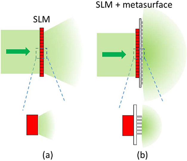
Figure 1 compares the working principles of a single SLM beam-steering system and a metasurface-coupled SLM beam-steering system. A simple SLM beam-steering system uses a SLM to directly perform beam steering [14]. However, as SLM pixels tend to be large in comparison to optical wavelength, the achievable steering angle tends to be small [see Fig. 1(a)]. The disorder-engineered metasurface is capable of scattering light uniformly within a range of −90° to 90° [Fig. 1(b)] due to the subwavelength size and random distribution of the nanoposts. By displaying the correct phase map on the SLM, constructive interference occurs, and light intensity is enhanced at the specified angle.
Fig. 1.
Comparison of steering range of a single SLM structure and a metasurface-coupled SLM structure. (a) Without the metasurface, the SLM can provide only a small diffraction envelope that is determined by pixel size, and thus can steer light only within a limited angular range. (b) With the metasurface-coupled SLM structure, since each scatterer is subwavelength, the steereable range can span from −90° to 90°.
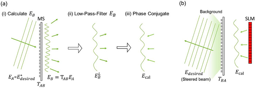
The required phase pattern to actuate beam steering in the desired direction can be calculated by using the principles of optical phase conjugation (OPC) [15], as shown in Fig. 2. In OPC, the input–output response of a scattering system can be characterized by a transmission matrix (from plane to ), with . The random scattering nature implies that the elements of follow an identical independent complex Gaussian distribution [16]. Due to optical reciprocity, (where (·)′ is the transpose operator). To realize a desired optical field [Fig. 2(b)], which corresponds to a beam steered at a specified angle, the optical field solution on the SLM, , is calculated by ((·)* is the conjugation operator), which first calculates the scattering speckle field of the beam from the desired direction [Fig. 2(a) (i)] and then phase conjugates it [Fig. 2(a) (iii)]. The output field is then (since is a complex Gaussian random matrix, [17]). In our case, is a diagonal matrix, with each element corresponding to the phase delay of each nanopost. To match the pixel size of the SLM, is low-pass filtered prior to being displayed on the SLM [Fig. 2(a) (ii)].
Fig. 2.
Process required to steer the beam is to (a) calculate the required phase pattern on the SLM and (b) display the phase pattern on the SLM and reflecting light off the SLM. Steps to calculate the phase pattern are as follows. (i) Assume there is an incident field with the desired steering angle incident on the metasurface (MS). Calculate the transmitted scattered field . (ii) In order to match the SLM pixel size to the scattered field speckle size, is low-pass filtered to be . (iii) is phase conjugated to get the phase pattern required on the SLM, . (b) The beam can then be steered by displaying the phase of on the SLM and reflecting light off the SLM and into the metasurface. SLM, spatial light modulator.
As a side note, we would like to point out that this procedure is related to our earlier work on using a disorder-engineered metasurface to render a record number of addressable diffraction-limited spots [13]. In fact, it is possible to use the same pair of SLM and disorder-engineered metasurface to perform both focused-spot rendering and beam steering. This flexibility is a key advantage of metasurface-coupled SLM wavefront shaping.
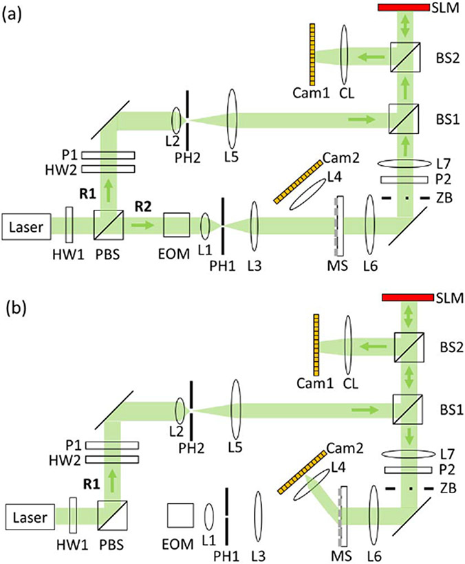
The optical setup for the disorder-engineered metasurface-coupled phased-array system for beam steering is shown in Fig. 3. We first accurately map the SLM onto the metasurface [Fig. 3(a)] and then use the aligned system to perform beam steering [Fig. 3(b)]. The laser beam (532 nm, 150 mW, CrystaLaser Inc. USA) is first split into two arms by a polarizing beam splitter (PBS). Light on arm R2 is scattered by the metasurface and interferes with light from arm R1 at BS1. The interference pattern is incident on the SLM (PLUTO, HOLOEYE) and camera (GX1920, Allied Vision), which are at conjugate planes with the metasurface. The SLM is demagnified 5× to match it to the size of the metasurface. An electro-optic modulator (EOM) adds a phase shift to the light on arm R2 in order to extract the phase of the light scattered by the metasurface, which is done using phase-shifting holography.
Fig. 3.
Schematic of the optical system, showing light path to (a) align the metasurface and (b) realize beam steering. BS, beam splitter; Cam, camera; CL, camera lens; EOM, electro-optic modulator; HW, halfwave plate; L, lens; M, mirror; MS, metasurface; P, polarizer; PH, pinhole; PBS, polarizing beam splitter; ZB, zeroth-order block.
Once the metasurface is aligned, the phase pattern required to steer the beam to a specific angle is determined and displayed on the SLM. Light from arm R2 is blocked, and light from arm R1 is modulated by the SLM in order to realize beam steering. [Fig. 3(b)]. The zeroth-order block removes the component of light from the SLM that remains unmodulated. L4 and camera 2 are moved to image the steered beam. The procedure to digitally align the metasurface to the rest of the system is as follows. First, the phase of the light scattered from the metasurface is calculated. This measured phase map is compared to the designed phase map using cross-correlation to determine the lateral position of the metasurface. Next, the axial position of the metasurface is determined by digitally propagating the measured field and comparing it to the designed phase map. Once the position of the metasurface is precisely determined, the optical aberrations of the system are characterized by segmenting the designed map and the measured field into a 2D array of 27 × 48 and taking their difference. Finally, using the parameters determined in digital alignment, the calculated pattern is displayed on the SLM to steer light.
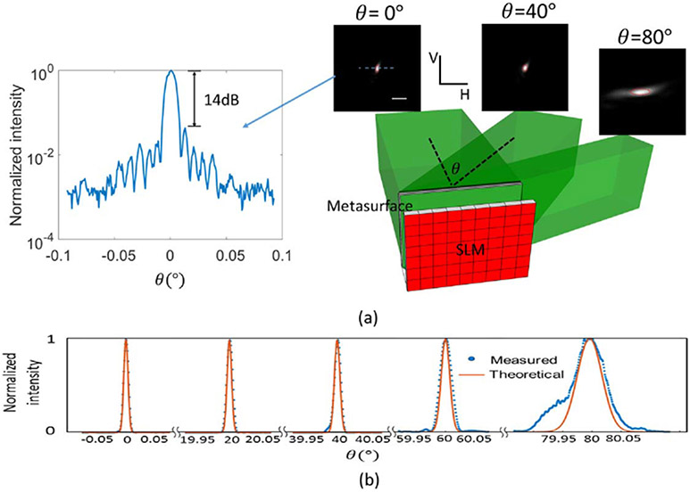
Figure 4(a) shows the steering system scheme and the far-field beam shapes at the steering angles of 0°, 40°, and 80°, acquired by moving the imaging system (L4 and Camera 2). The elliptical shape of the beam is due to the rectangular aperture shape on the metasurface. The 1D line profile at 0° is also plotted, showing a high signal-to-background ratio (14 dB). In Fig. 4(b), we show 1D shapes of the far-field beams at other steering angles ranging from 0° to 80°. From the figure, we can see that our measured angular resolution matches the theoretical calculation very well. As the steering angle increases, the beam divergence is enlarged due to the projection effect of the emitting aperture. That is, when viewing at an angle, the system aperture size is scaled by a cosine factor. Experimentally, the steerable range was 160° (from normal incidence to 80°, due to measurement limit), and the angular resolution for steering angles near 0° was 0.01° and 0.018° in two axes, respectively. The illumination area on the metasurface is 3.1 mm × 1.7 mm, which has the theoretical angular resolution on both axes the same as experimental results. The average beam divergence within the steering range was 0.017° and 0.03° in two axes. From the results above, the system should be able to steer the beam to 5 × 10⁷ resolvable directions in 2D (about 104 in 1D), which is 3 orders of magnitudes greater than previously reported phased-array performance [11]. In comparison, the SLM has 1080 × 1920 pixels, yielding 2 × 10⁶ nominal degrees of control and possible resolvable steering direction.
Fig. 4.
(a) Illustration of the steering scheme ( imaging system for imaging the SLM to the metasurface is not shown here). The far-field beam shapes at the steering angles of 0°, 40°, and 80° are shown. The red circles enclose the theoretical FWHM of the beams. The intensity line profile at normal direction is shown. (b) 1D far-field beam shapes at other steering angles. Red lines denote the theoretical shapes of the beams. Blue dots denote the measured data. Scale bar: 0.05° V, vertical axis; H, horizontal axis.
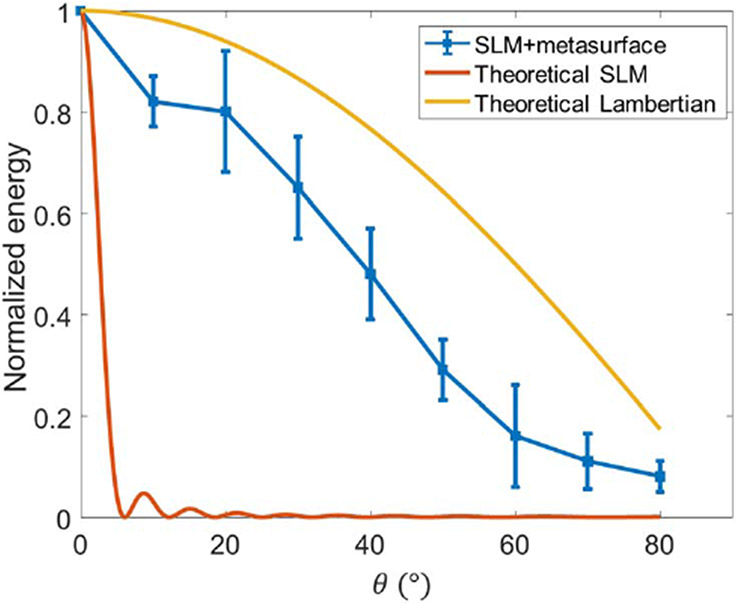
Figure 5 shows the beam energy as a function of steering angle. The drop off in energy at larger angles is expected due to the cosine dependency of the visible system aperture when viewed at an angle. We can see that the performance of the metasurface-coupled system (in blue) is significantly better than the SLM only system (red). In fact, the metasurface-coupled system is capable of steering beams substantially beyond the 5° range limitation of the SLM (red). For comparison, we have also plotted the profile associated with a Lambertian source (yellow), which represents the theoretical upper bound.
Fig. 5.
Normalized beam energy versus steering angle for our metasurface-coupled SLM system (blue) in comparison to an SLM-only beam-steering system (red). The performance of a Lambertian source (yellow) is included to show the theoretical upper bound. All of the curves are normalized based on the energy at .
Table 1 compares the best steering performance achieved by a selection of phased-array methods reported in the literature. To our knowledge, our method provides the best reported performance in terms of steering range and number of resolvable directions among phased arrays. This is consistent with our expectation that the metasurface is capable of spreading light over a large angular range while still “preserving” the original aperture size of the SLM to provide sharp angular resolution. However, the throughput of our system, defined as the ratio of the power in the directed beam direction versus the total output power, is very low.
Table 1.
Comparison of Steering Performance of Different Phased-Array Methods
| Range | Resolution | (1D) | Throughput | |
|---|---|---|---|---|
| Hutchison [11] | 80° | 0.14° | 500 | Not mentioned |
| Haellstig [14] | 4° | <0.005° | 800a | 68% |
| Metasurface-coupled phased array | 160° | 0.017° | 9.4 × 10³ | 1.0 × 10⁻⁶ |
Calculated from range and resolution.
The throughput is expressed as , where is the degrees of control on the SLM, is the number of optical modes in the system aperture, is due to the phase-only modulation of the SLM [18], and is an empirical factor that accounts for experimental imperfections. For an ideal system, should equal 1. Here, the optical mode set is defined as the set of basis vectors that are needed to characterize the output electric field. is calculated as , where is the aperture area, and is the wavelength of light [19]. In our experiment, is ~3.8 × 10⁻³ due to the metasurface fabrication imperfection and residual optical system misalignment.
This tradeoff of throughput for increased number of resolvable directions is a direct consequence of the fact that we have used the metasurface to access a much larger beam-steering range without increasing the number of SLM control elements. For applications where power inefficiency is not an issue, our method is an effective solution to substantially increase the number of resolvable steering-beam directions. We would like to draw attention to the fact that the peak-to-background contrast of the steered beam can be substantial even though the throughput is low; the measured contrast ratio was 23 (14 dB) in the experiment described by Fig. 4(a).
In effect, the conventional SLM phased array and our metasurface-coupled phased array differ in performance emphasis. To see this, consider a given system aperture size A and number of control elements . For a conventional SLM phased array, as increases, the throughput of the SLM remains fixed, but the number of resolvable steering directions increases. The situation is reversed for the metasurface-coupled phased array. As increases, the number of resolvable steering directions stays fixed while the throughput increases. In the limiting case where , both types of phased arrays are expected to have the same theoretical throughput and number of steering directions.
We believe that the concept of equipping an active phased array with a passive disorder-engineered metasurface can be employed by current chip-based phased array methods that suffer from the tradeoff between steerable range and angular resolution. The cost of a passive metasurface with subwavelength scatterers and a large aperture is much lower than that of a highly integrated chip. Moreover, since the transmission property of the metasurface is known, instead of optical phase conjugation, other algorithms, such as transmission matrix inversion [17], can be used for customized applications. For instance, the algorithm in Ref. [17] allows the beam-steering system to provide lower background intensity within a given steering range than the phase conjugation algorithm. Currently, the metasurface is designed at 532 nm, and we can expect the system performance to deteriorate if the operating wavelength is changed. One potential strategy is to design the metasurface so that the nanoposts confer a broader range of phase delays from 0 to where is a large integer. This way, a wavelength shift will have a smaller impact on the overall phase delay distribution profile. This is an area that deserves further study and optimization.
In summary, we have demonstrated a disorder-engineered metasurface-coupled phased-array-based beam-steering system with a large steering range and narrow beam divergence, which provides us with more resolvable directions at the cost of throughput. The enhancement of steering range is attributable to the subwavelength scatterers, and the high angular resolution is attributable to the large aperture of the metasurface. Since the phase map of the metasurface is known a priori, the phase solution on the SLM for any specified steering angle within the steering range can be found computationally after alignment. This idea of a disorder-engineered metasurface-coupled phased-array method offers an effective solution to the range-resolution tradeoff in traditional phased-array methods, and can potentially be applied in lidar, free-space optical communications, and optical interconnects.
Acknowledgment
We thank Dr. Atsushi Shibukawa, Dr. Haowen Ruan, and Dr. Yan Liu for helpful discussions.
Funding
National Institutes of Health (NIH) (NIH-R21EY026228A); Natural Sciences and Engineering Research Council of Canada (NSERC) (NSERC PGSD3).
REFERENCES
- 1.Schwarz B, Nat. Photonics 4, 429 (2010). [Google Scholar]
- 2.Feng F, White IH, and Wilkinson TD, J. Lightwave Technol 31, 2001 (2013). [Google Scholar]
- 3.Henderson CJ, Leyva DG, and Wilkinson TD, J. Lightwave Technol 24, 1989 (2006). [Google Scholar]
- 4.Duncan BD, Opt. Eng 43, 2312 (2004). [Google Scholar]
- 5.Bos PJ, Opt. Eng 42, 1038 (2003). [Google Scholar]
- 6.Jofre M, Anzolin G, Steinlechner F, Oliverio N, Torres JP, Pruneri V, and Mitchell MW, Opt. Express 20, 12247 (2012). [DOI] [PubMed] [Google Scholar]
- 7.Yaacobi A, Sun J, Moresco M, Leake G, Coolbaugh D, and Watts MR, Opt. Lett 39, 4575 (2014). [DOI] [PubMed] [Google Scholar]
- 8.Sun J, Hosseini ES, Yaacobi A, Cole DB, Leake G, Coolbaugh D, and Watts MR, Opt. Lett 39, 367 (2014). [DOI] [PubMed] [Google Scholar]
- 9.Aflatouni F, Abiri B, Rekhi A, and Hajimiri A, Opt. Express 23, 21012 (2015). [DOI] [PubMed] [Google Scholar]
- 10.Abediasl H and Hashemi H, Opt. Express 23, 6509 (2015). [DOI] [PubMed] [Google Scholar]
- 11.Hutchison DN, Sun J, Doylend JK, Kumar R, Heck J, Kim W, Phare CT, Feshali A, and Rong H, Optica 3, 887 (2016). [Google Scholar]
- 12.Tholl HD, Proc. SPIE 6397, 639708 (2006). [Google Scholar]
- 13.Jang M, Horie Y, Shibukawa A, Brake J, Liu Y, Kamali SM, Arbabi A, Ruan H, Faraon A, and Yang C, Nat. Photonics 12, 84 (2018). [DOI] [PMC free article] [PubMed] [Google Scholar]
- 14.Haellstig E, Stigwall J, Lindgren M, and Sjoqvist L, Proc. SPIE 5087, 13 (2003). [Google Scholar]
- 15.Yaqoob Z, Psaltis D, Feld MS, and Yang C, Nat. Photonics 2, 110 (2008). [DOI] [PMC free article] [PubMed] [Google Scholar]
- 16.Freund I, J. Stat. Phys 130, 413 (2007). [Google Scholar]
- 17.Xu J, Ruan H, Liu Y, Zhou H, and Yang C, Opt. Express 25, 27234 (2017). [DOI] [PMC free article] [PubMed] [Google Scholar]
- 18.Vellekoop IM and Mosk AP, Opt. Lett 32, 2309 (2007). [DOI] [PubMed] [Google Scholar]
- 19.Mosk AP, Lagendijk A, Lerosey G, and Fink M, Nat. Photonics 6, 283 (2012). [Google Scholar]


