

Abstract
On-body antennas for use in microwave imaging (MI) systems can direct energy around the body instead of through the body, thus degrading the overall signal-to-noise ratio (SNR) of the system. This work introduces and quantifies the usage of modern metal-backed RF absorbing foam in conjunction with on-body antennas to dampen energy flowing around the body, using both simulations and experiments. A head imaging system is demonstrated herein but the principle can be applied to any part of the body including the torso or extremities. A computational model was simulated numerically using Ansys HFSS. A physical prototype in the form of a helmet with embedded antennas was built to compare simulations with measured data. Simulations and measurements demonstrate that usage of such metal-backed RF-absorbing foams can significantly reduce around-body coupling from Transmit (Tx) and Receive (Rx) antennas by approximately 10dB. Thus, the overall SNR of the MI system can be substantially improved using this low-cost and affordable method.
Keywords: Antennas and propagation, Biomedical imaging, Electromagnetic propagation in absorbing media, Microwave imaging, Microwave measurements, Numerical simulation, Surface waves
Graphical Abstract

Poynting vector magnitude distribution on the surface of the body when excited with a microwave imaging system; traditional (left) vs. proposed design (right).
I. Introduction
MICROWAVE imaging (MI) is a powerful medical diagnostic tool that leverages the changes in internal tissues’ dielectric properties due to trauma or illness, to locate and identify the tissue of interest [1]. Its fundamental principle is electromagnetic scattering. A single antenna assembly excites signals toward the tissue’s location of interest. If pathology (e.g., a hemorrhage or tumor) is present, the signals can be modulated by the targeted tissue relative to other adjacent normal and healthy tissues. Subsequently the scattered signals are then received by other antenna assemblies at different locations. Through similar RADAR target imaging algorithms, the position of the targeted tissue may be constructed in a 3D map [2],[3]. In recent years, there have been ongoing developments and innovations in this space to further enhance the accuracy of image captures [4]–[6].
One significant issue of concern with MI systems is that the on-body antennas intended to transmit RF energy through the body also inherently transmit energy that flows around the outer surface of the body [7]–[9]. This known phenomenon is regularly exploited by designers of on-body RF communication systems [10]–[17]. The energy traveling through air and around the surface of the body is considered parasitic in the case of MI systems since it is not modulated by the tissue intended for imaging. Furthermore, the energy which travels outside the body is larger in magnitude and arrives earlier than the energy which travels through the lossy high dielectric human body. Therefore, suppressing transmission of energy that does not flow through the tissue under test is critical to improve the signal-to-noise ratio (SNR) of the detected image in MI systems.
Previous efforts to reduce these so called ‘surface waves’ have been implemented by special design of the antenna itself, utilizing distributed structures within the substrate [18]–[20], electromagnetic band gap (EBG) structures [21]–[23], frequency selective surfaces (FSS) [24]–[26], and metamaterials [27],[28]. While each of these methods have been shown to reduce surface wave transmission, they are typically limited to a narrow frequency band of operation, require additional care in the design of the antenna, and result in a design with either an increase in physical size, design complexity, and/or cost to manufacture. Another method is use of a liquid-filled bolus between the antenna and body [29]–[31]. In this case, there is no air-to-tissue interface for the surface wave to propagate. While this technique offers the additional advantage of wideband antenna impedance matching, it requires the tissue under test to either be fully submersed in a liquid, or a sealed housing to contain the liquid must be factored into the antenna design, again increasing the size, complexity, and cost of the MI system.
This work is the first to propose the novel use of commercially available RF absorbing foams [33],[33] to attenuate energy traveling outside and around the tissue under test in MI systems. The proposed method can be implemented with any MI system utilizing on-body antennas by simply surrounding the tissue volume under test with a layer of RF absorbing foam (with foam removed around the antenna), followed by a layer of metal foil which acts as both a shield to limit radiation out into space as well as a reflector to redirect unabsorbed RF energy back into foam for further absorption.
The main advantage of the proposed method is its effectiveness relative to its simplicity, low cost, and ease of implementation. RF absorbing foam and metal foil are relatively inexpensive and flexible materials and can be cut and formed to the required dimensions without any specialized tools. Additionally, while a head imaging system is demonstrated in this work, this method can be generally applied to any MI system utilizing on-body antennas for imaging any part of the body.
To demonstrate the proposed method, a prototype MI system was designed, constructed, and tested. Simulations were computed and measurements were performed for two cases – the MI system with and without the proposed prototype helmet. Results show that the proposed system was able to significantly reduce energy propagation outside the body without any significant impact to the performance of the Tx/Rx antennas, thus improving the overall SNR of the MI system.
II. Materials and methods
A. Numerical Simulation Setup
Numerical simulations were performed using the commercial finite element method (FEM) solver Ansys Electronics Desktop HFSS 2021 R2 (Ansys, Inc. Canonsburg, PA, USA) to evaluate the proposed method. Figs. 1 and 2 show the two models were created, one without and one with the proposed prototype helmet respectively. Each model is comprised of a single Tx antenna and single Rx antenna positioned on the left and right temples respectively of the Ansys Visual Human Project (VHP) human body model [34][34]. The antennas utilized in the model are custom made 2.45GHz dual antiphase patch antennas which include the full design of the resonator geometry, integrated balun, and impedance-matching circuitry [35]. The human body model is limited to the reactive near-field region of the head, neck, and shoulder structures for efficient usage of computational resources. The only difference between the two simulated models is the presence of the proposed helmet containing the metal-backed RF absorbing foam. Material properties for the human body model were taken from Italian National Research Council database [36]. Material properties for the RF absorbing foam were provided directly by the manufacturer. Convergence of the simulation was accounted for by evaluating the maximum change in the magnitude of any component of the solved S-Parameter matrix of the two-port system between two subsequent solved passes with increasing tetrahedral mesh density, the so-called ‘max mag delta S’ parameter within HFSS. The target max mag delta S was set to 0.00001 to ensure accuracy of the simulation S21 values down to −100dB. The final solved mesh for the model without the helmet utilized 5.4 million tetrahedron, consumed 0.96 TB RAM, and converged with max mag delta S = 0.000007. The final solved mesh for the model with the helmet utilized 9.46 million tetrahedron, consumed 1.35 TB RAM, and converged with max mag delta S = 0.000005.
Fig. 1.

HFSS model of a generic microwave imaging system of the head with one Tx antenna and one Rx antenna.
Fig. 2.

HFSS model of a generic microwave imaging system of the head augmented with proposed prototype helmet.
B. RF Absorbing Foam Selection & Prototype Design
The RF absorbing foam selected for this study was Laird Eccosorb LS-30, which provides the highest magnitude of RF attenuation compared to other commercially available RF absorbing foams at the system’s frequency of operation [37]. At 2.45 GHz, the foam has a relative dielectric constant of approximately 20 and dielectric loss tangent of approximately 5. A generic off-the-shelf plastic safety helmet was augmented using the proposed method by first adding a 1mm thick layer of adhesive-backed copper foil to the inner surface of the helmet. Next, a 10mm thick layer of LS-30 foam (which includes a layer of adhesive on one side) was cut and fit into the inner surface of the helmet. Lastly, cutouts in the foam were made at the antenna placement locations and cutouts in the metal layer were made to allow connection to the antenna MMCX connectors. Fig. 3 shows a detailed view of the design as modeled in Ansys HFSS.
Fig. 3.

(A) Antenna placement on head, (B) foam layer added, (C) metal layer added, (D) complete design (cross-section view)
C. Measurement Setup
Fig. 4 shows photos of the physically realized system. S-Parameter measurements were collected using an HP8722ET vector network analyzer (VNA) with intermediate frequency resolution bandwidth (IFRBW) setting of 30 Hz, and output power of −5 dBm. S-Parameter magnitude and phase data were collected at 2.45GHz for each of two subjects. All subjects were approved via IRB. Given the low power level, multiple measurements were taken and averaged to reduce noise in the measurement. Note that the plastic helmet was not included in any of the simulations, as the electric field magnitude outside the helmet was found to be significantly attenuated so as not to interact with the system.
Fig. 4.

Measurement setup: assembled metal-backed foam helmet, (A) front view on subject, (B) top-down view
III. Results & Discussion
A. Near Field Simulation – Poynting Vector
Near fields were computed for each model. In order to compensate for the difference in matching between the two cases, the incident power of the case with helmet was scaled so as to match the resultant accepted power of the case without the helmet (i.e. both cases compared in this section have the same accepted power into the system). To evaluate the flow of electromagnetic power spatially distributed throughout the model, the magnitude of the Poynting vector was computed both through and around the head. Fig. 5 shows the Poynting vector magnitude plot through the coronal plane, centered about the antenna apertures, for each case. Fig. 6 shows the Poynting vector magnitude plot through the transverse plane, centered about the antenna apertures, for each case.
Fig. 5.

Poynting vector magnitude |S| plot through the coronal plane, centered at the antenna apertures, (top) no helmet, (bottom) with helmet
Fig. 6.

Poynting vector magnitude |S| plot through the transverse plane, centered at the antenna apertures, (top) no helmet, (bottom) with helmet
In both figures, it is observed that the Poynting vector magnitude outside the head near the Rx antenna has been reduced by approximately two orders of magnitude, while the magnitude inside the head has only been reduced by approximately one order of magnitude.
Fig. 7 shows the Poynting vector magnitude on the surface of the skin. In this figure, it is observed that the power density on the surface of the head has been significantly reduced in the case with the proposed helmet as expected.
Fig. 7.

Poynting vector magnitude |S| plot on the surface of the skin. (top) no helmet, (bottom) with helmet
In order to better evaluate the distribution of power flow in and around the head, two paths between the antenna apertures (as defined in Fig. 8) were chosen to be plot separately as line plots. Note in Fig. 9 that the x-axis is the normalized distance from the Tx aperture to the Rx aperture as these paths are of two different physical lengths, i.e. the line plot for the longer path around the head was compressed to fit within the same x-axis bounds.
Fig. 8.

Two sampled paths, one through and one around the head, were used to evaluate the magnitude of the Poynting vector vs. distance in Fig 9.
Fig. 9.

Magnitude of the Poynting vector plot vs. normalized distance between Tx aperture and Rx aperture for each path with and without the helmet
Here it is observed that the Poynting vector magnitude along the path through the head is similar but with a constant offset when comparing the cases with and without the helmet. Conversely it is observed that for the path around the head, the Poynting vector magnitude for the case with the helmet has a more negative slope, indicating the power traveling around the head as it approaches the Rx antenna has again been reduced by an order of magnitude more than the reduction through the head, the same as observed in Figs. 5 and 6.
B. Far Field Simulation – Antenna Gain
Fig. 10 shows a comparison of the simulated far-field radiation patterns taken at two cut-planes (phi = 0° & phi = 90°) for the models with and without the foam/metal helmet. As in the previous section, the incident power of the case with helmet was scaled so as to match the accepted power of the case without the helmet. Here it is observed that the addition of the foam/metal helmet reduces the antenna system’s far-field gain by more than 20dB in every direction. This result shows that use of the helmet significantly reduces the radiated power from the Tx antenna that could potentially couple to the Rx antenna outside the body.
Fig. 10.
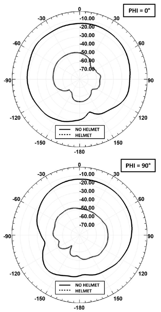
Far-Field gain pattern [dB], with vs. without helmet
C. Power Budget Comparison
Power budget tables were computed for each simulation model to evaluate the amount of power lost in various components of the system. Table 1 presents a power budget analysis for the case with the antennas mounted directly on the head without the helmet. Table 2 presents a power budget analysis for the model with the helmet. Comparing the two cases, it is observed that total power dissipated in the tissue in the case without the helmet is equal to the power dissipated in the tissue and foam. The simulations account for any mismatch losses of the antenna which is demonstrated by the different levels of accepted power into the system between the two cases. It is also observed that the radiated power has been significantly attenuated, as in agreement with the previous section.
Table 1.
Power Budget – No Helmet
| Quantity | [W] | Accepted Power [%] |
|---|---|---|
| Accepted Power | 5.39E-03 | 100.0 |
| Power at Rx | 9.60E-11 | 0.00000178 |
| Radiated Power | 7.10E-05 | 1.32 |
| Loss in Tissue | 3.84E-03 | 71.8 |
| Loss in Antenna | 2.19E-04 | 4.07 |
| Loss in Foam | - | - |
| Loss in Balun | 1.17E-03 | 21.7 |
| Unaccounted | 1.1 |
Table 2.
Power Budget – With Helmet
| Quantity | [W] | Accepted Power [%] |
|---|---|---|
| Accepted Power | 4.53E-03 | 100.0 |
| Power at Rx | 6.23E-12 | 0.00000014 |
| Radiated Power | 1.09E-07 | 0.002 |
| Loss in Tissue | 2.73E-03 | 60.3 |
| Loss in Antenna | 2.39E-04 | 5.28 |
| Loss in Foam | 5.48E-04 | 12.09 |
| Loss in Balun | 9.73E-04 | 21.5 |
| Unaccounted | 0.9 |
D. S-Parameters
S-Parameters were simulated and measured at 2.45GHz. Table 3 lists a summary of S21 for cases with and without the helmet for simulation and measurements from two subjects. It is observed here that simulations and measurements show good agreement with an average of approximately −10dB difference in the received signal strength comparing the cases with and without the helmet. These results are again in agreement with all previously reported results.
Table 3.
Antenna-to-Antenna Coupling (S21) at 2.45GHz
| Case | S21 [dB] No Helmet | S21 [dB] With Helmet | Difference [dB] |
|---|---|---|---|
| Simulation | −80 | −92 | −12 |
| Measured: Subject 1 | −74 | −85 | −11 |
| Measured: Subject 2 | −77 | −86 | −9 |
IV. Conclusion
A novel method for reducing non-through body energy transfer in MI systems has been presented. System performance was analyzed using numerical simulations, a physical prototype was built, and measurements on human subjects were all found to be in good agreement and demonstrate the effectiveness of the proposed method. It is of note that the antennas used in this study were not initially designed for use with the proposed foam and metal helmet, yielding a 26% loss in accepted power into the transmitter. Redesigning the antennas for better matching in the presence of the adjacent foam could further increase the SNR of the MI system. In conclusion, this work demonstrates that the usage of modern RF absorbing foams in this proposed manner can increase the SNR of an MI system by a factor equivalent to the relative contribution of non-through body coupling.
Take-Home Messages.
This manuscript presents a novel approach to reduce non-through body energy propagation in microwave imaging systems using modern RF absorbing foam materials.
Use of RF absorbing foams can increase the SNR of a microwave imaging system by a factor relative to the contribution of non-through body energy propagation.
The targeted application is microwave imaging.
This is the first use of RF absorbing foam materials implemented in a microwave imaging system.
This technique can be applied to microwave imaging of any biological tissue.
Acknowledgment
The authors would like to acknowledge Nick Fleming, Michelle Heitzman, and Paul Dixon of Laird for their discussion on RF absorbing foam selection and W. L. Appleyard of WPI for his assistance in the design and construction of the prototype helmet.
This work was supported in whole by the authors.
Contributor Information
Peter Serano, Worcester Polytechnic Institute, Worcester, MA USA 01609.
Johnathan W. Adams, Worcester Polytechnic Institute, Worcester, MA USA 01609.
Louis Chen, Worcester Polytechnic Institute, Worcester, MA USA 01609.
Ara Nazarian, Beth Israel Deaconess Medical Center, Harvard Medical School, Boston, MA 02215.
Reinhold Ludwig, Worcester Polytechnic Institute, Worcester, MA USA 01609.
Sergey Makaroff, Worcester Polytechnic Institute, Worcester, MA USA 01609.
References
- [1].Fhager A, Candefjord S, Elam M, Persson M, “Microwave Diagnostics Ahead”, IEEE Microwave Magazine, April 2018 [Google Scholar]
- [2].Grzegorczyk TM, Meaney PM, Kaufman PA, di Florio-Alexander RM and Paulsen KD, “Fast 3-d tomographic microwave imaging for breast cancer detection”, Medical Imaging IEEE Transactions on, vol. 31, no. 8, pp. 1584–1592, Aug 2012. [DOI] [PMC free article] [PubMed] [Google Scholar]
- [3].Fear EC, Bourqui J, Curtis C, Mew D, Docktor B and Romano C, “Microwave breast imaging with a monostatic radar-based system: A study of application to patients”, Microwave Theory and Techniques, vol. 61, no. 5, pp. 2119–2128, May 2013. [Google Scholar]
- [4].Chandra R, Zhou H, Balasingham I, Narayanan R, “On the Opportunities and Challenges in Microwave Medical Sensing and Imaging”, IEEE Trans. on Biomedical Engineering, Vol. 62, No. 7, July 2015 [DOI] [PubMed] [Google Scholar]
- [5].Rodriguez-Duarte D, Tobon Vasquez J, Scapaticci R, Crocco L, Vipiana F, “Assessing a Microwave Imaging System for Brain Stroke Monitoring via High Fidelity Numerical Modeling”, IEEE Journal of Electromagnetics, RF, and Microwave in Medicine and Biology, Vol. 5, No. 3, September 2021 [Google Scholar]
- [6].Fedeli A, Estatico C, Pastorino M, Randazzo A, “Microwave Detection of Brain Injuries by Means of a Hybrid Imaging Method”, IEEE Open Journal of Antennas and Propagation, Sept 2020 [Google Scholar]
- [7].Petrovic N, Otterskog M and Risman PO, “Antenna applicator design for microwave imaging of the interior of human breasts”, Journal of Physics D: Applied Physics, vol. 47, no. 38, June 2014. [Google Scholar]
- [8].Bae J, Cho H, Song K, Lee H and Yoo H-J, “The Signal Transmission Mechanism on the Surface of Human Body for Body Channel Communication,” in IEEE Transactions on Microwave Theory and Techniques, vol. 60, no. 3, pp. 582–593, March 2012, doi: 10.1109/TMTT.2011.2178857. [DOI] [Google Scholar]
- [9].Grimm M and Manteuffel D, “Norton Surface Waves in the Scope of Body Area Networks,” in IEEE Transactions on Antennas and Propagation, vol. 62, no. 5, pp. 2616–2623, May 2014, doi: 10.1109/TAP.2014.2307347. [DOI] [Google Scholar]
- [10].Conway GA and Scanlon WG, “Antennas for Over-Body-Surface Communication at 2.45 GHz,” in IEEE Transactions on Antennas and Propagation, vol. 57, no. 4, pp. 844–855, April 2009, doi: 10.1109/TAP.2009.2014525. [DOI] [Google Scholar]
- [11].Khouri R, Ratajczak P, Brachat P and Staraj R, “A thin surface-wave antenna using a via-less EBG structure for 2.45 GHz ON-Body communication systems,” Proceedings of the Fourth European Conference on Antennas and Propagation, Barcelona, Spain, 2010, pp. 1–4. [Google Scholar]
- [12].Akhoondzadeh-Asl L, Nechayev Y and Hall PS, “Surface and creeping waves excitation by body-worn antennas,” 2010 Loughborough Antennas & Propagation Conference, Loughborough, UK, 2010, pp. 48–51, doi: 10.1109/LAPC.2010.5666805. [DOI] [Google Scholar]
- [13].Akhoondzadeh-Asl L, Hall PS and Nechayev Y, “Novel conformal surface wave Yagi antenna for on-body communication channel,” 2010 IEEE Antennas and Propagation Society International Symposium, Toronto, ON, Canada, 2010, pp. 1–4, doi: 10.1109/APS.2010.5561915. [DOI] [Google Scholar]
- [14].Akhoondzadeh-Asl L, Nechayev Y, Hall PS and Constantinou CC, “Parasitic Array Antenna With Enhanced Surface Wave Launching for On-Body Communications,” in IEEE Transactions on Antennas and Propagation, vol. 61, no. 4, pp. 1976–1985, April 2013, doi: 10.1109/TAP.2012.2231918. [DOI] [Google Scholar]
- [15].Choi J, Tak J and Kwon K, “Low-profile antennas for on-body surface communications,” 2014 International Workshop on Antenna Technology: Small Antennas, Novel EM Structures and Materials, and Applications (iWAT), Sydney, NSW, Australia, 2014, pp. 288–291, doi: 10.1109/IWAT.2014.6958666. [DOI] [Google Scholar]
- [16].Pleskachev V, Vendik I, Vendik O, Kirillov V, Turalchuk P and Odit M, “On-body surface electromagnetic wave propagation: Modeling and measurements,” 2016 10th European Conference on Antennas and Propagation (EuCAP), Davos, Switzerland, 2016, pp. 1–5, doi: 10.1109/EuCAP.2016.7481853. [DOI] [Google Scholar]
- [17].Berkelmann L and Manteuffel D, “Implantable Antenna Design for Surface-Wave Based In-Body to On-Body Communications,” 2021 IEEE International Symposium on Antennas and Propagation and USNC-URSI Radio Science Meeting (APS/URSI), Singapore, Singapore, 2021, pp 809–810, doi: 10.1109/APS/URSI47566.2021.9704714. [DOI] [Google Scholar]
- [18].Jackson DR, Williams JT, Bhattacharyya AK, Smith RL, Buchheit SJ and Long SA, “Microstrip patch designs that do not excite surface waves,” in IEEE Transactions on Antennas and Propagation, vol. 41, no. 8, pp. 1026–1037, Aug. 1993, doi: 10.1109/8.244643. [DOI] [Google Scholar]
- [19].Papapolymerou I, Drayton RF and Katehi LPB, “Surface wave mode reduction for rectangular microstrip antennas,” IEEE Antennas and Propagation Society International Symposium. 1995 Digest, Newport Beach, CA, USA, 1995, pp. 1494–1497 vol.3, doi: 10.1109/APS.1995.530859. [DOI] [Google Scholar]
- [20].Yook Jong-Gwan and Katehi LPB, “Micromachined microstrip patch antenna with controlled mutual coupling and surface waves,” in IEEE Transactions on Antennas and Propagation, vol. 49, no. 9, pp. 1282–1289, Sept. 2001, doi: 10.1109/8.947019. [DOI] [Google Scholar]
- [21].Gonzalo R, De Maagt P and Sorolla M, “Enhanced patch-antenna performance by suppressing surface waves using photonic-bandgap substrates,” in IEEE Transactions on Microwave Theory and Techniques, vol. 47, no. 11, pp. 2131–2138, Nov. 1999, doi: 10.1109/22.798009. [DOI] [Google Scholar]
- [22].Rajo-Iglesias E, Quevedo-Teruel O and Inclan-Sanchez L, “Mutual coupling reduction in patch antenna arrays by using a planar EBG structure and a multilayer dielectric substrate,” in IEEE Transactions on Antennas and Propagation, vol 56, no. 6, pp. 1648–1655, Jun 2008. [Google Scholar]
- [23].Bertuch T et al. , “Experimental investigation of EBG surface performance for suppression of undesired waves on phased array antennas,” 2013 International Conference on Electromagnetics in Advanced Applications (ICEAA), Turin, Italy, 2013, pp. 988–991, doi: 10.1109/ICEAA.2013.6632388. [DOI] [Google Scholar]
- [24].Colburn JS and Rahmat-Samii Y, “External substrate perforation applied to patch antennas for mitigating surface wave effects,” IEEE Antennas and Propagation Society International Symposium. 1999 Digest. Held in conjunction with: USNC/URSI National Radio Science Meeting (Cat. No.99CH37010), Orlando, FL, USA, 1999, pp. 1928–1931 vol.3, doi: 10.1109/APS.1999.788335 [DOI] [Google Scholar]
- [25].Manga AA, Gillard R, Loison R, Le Roy-Naneix I and Renard C, “Implementation of a correcting coupling mechanism to mitigate surface wave in phased arrays,” 12th European Conference on Antennas and Propagation (EuCAP 2018), London, UK, 2018, pp. 1–4, doi: 10.1049/cp.2018.0520. [DOI] [Google Scholar]
- [26].Askarian A, Yao J, Lu Z and Wu K, “Surface-Wave Control Technique for Mutual Coupling Mitigation in Array Antenna,” in IEEE Microwave and Wireless Components Letters, vol. 32, no. 6, pp. 623–626, June 2022, doi: 10.1109/LMWC.2021.3139196. [DOI] [Google Scholar]
- [27].Burkholder RJ, “FEKO™ Analysis of Surface Treatments for Mitigating the EM Coupling Between Conformal Antennas,” 2019 International Applied Computational Electromagnetics Society Symposium (ACES), Miami, FL, USA, 2019, pp. 1–2. [Google Scholar]
- [28].Liu F, Guo J, Zhao L, Huang G-L, Li Y and Yin Y, “Dual-Band Metasurface-Based Decoupling Method for Two Closely Packed Dual-Band Antennas,” in IEEE Transactions on Antennas and Propagation, vol. 68, no. 1, pp. 552–557, Jan. 2020, doi: 10.1109/TAP.2019.2940316. [DOI] [Google Scholar]
- [29].Choi Woo Cheol, Kim Ki Joon and Yoon Young Joong, “Design of FSS unit-cell integrated in water bolus for microwave biomedical application,” 2014 IEEE International Workshop on Electromagnetics (iWEM), Sapporo, 2014, pp. 265–266, doi: 10.1109/iWEM.2014.6963738. [DOI] [Google Scholar]
- [30].Meaney PM, Fox CJ, Geimer SD, and Paulsen KD. Electrical characterization of glycerin: Water mixtures: Implications for use as a coupling medium in microwave tomography. IEEE Transactions on Microwave Theory and Techniques, 65(5):1471–1478, May 2017. [DOI] [PMC free article] [PubMed] [Google Scholar]
- [31].Petrović N, Pichot C and Risman PO, “Further Developments of Applicator Concepts for Detection of Body Part Inhomogeneities,” 2019 IEEE Conference on Antenna Measurements & Applications (CAMA), Kuta, Bali, Indonesia, 2019, pp. 218–221, doi: 10.1109/CAMA47423.2019.8959590. [DOI] [Google Scholar]
- [32].Kuzhir PP et al. , “Highly porous conducting carbon foams for electromagnetic applications,” International Symposium on Electromagnetic Compatibility - EMC EUROPE, Rome, Italy, 2012, pp. 1–4, doi: 10.1109/EMCEurope.2012.6396811. [DOI] [Google Scholar]
- [33].Chenu S, Coupez J-P, Karpus F and Toublanc B, “Development of new technologies using foam materials for RF device integration,” 2013 European Microwave Conference, Nuremberg, Germany, 2013, pp. 326–329, doi: 10.23919/EuMC.2013.6686657. [DOI] [Google Scholar]
- [34].Noetscher G, Serano P, Wartman W, Fujimoto K, and Makarov S. “Visible Human Project® female surface based computational phantom (Nelly) for radio-frequency safety evaluation in MRI coils.” PLoS One, vol 16, no. 12, Dec. 2021, doi: 10.1371/journal.pone.0260922. [DOI] [PMC free article] [PubMed] [Google Scholar]
- [35].Adams J, et al. “Miniaturized Dual Antiphase Patch Antenna Radiating into the Human Body at 2.4 GHz”, Under Review at IEEE Transactions on Antennas and Wireless Propagation [DOI] [PMC free article] [PubMed] [Google Scholar]
- [36].Andreuccetti D, Fossi R and Petrucci C: An Internet resource for the calculation of the dielectric properties of body tissues in the frequency range 10 Hz - 100 GHz. IFAC-CNR, Florence (Italy), 1997. Based on data published by C.Gabriel et al. in 1996. [Online]. Available: http://niremf.ifac.cnr.it/tissprop/
- [37].Laird, “Eccosorb LS”, RFP-DS-LS 070116,2015, Available Online: https://www.laird.com/sites/default/files/2021-01/RFP-DS-LS%2018062020.pdf