Abstract
As the expansion of Cone Beam CT (CBCT) to new interventional procedures continues, the burdensome challenge of metal artifacts remains. Photon starvation and beam hardening from metallic implants and surgical tools in the field of view can result in the anatomy of interest being partially or fully obscured by imaging artifacts. Leveraging the flexibility of modern robotic CBCT imaging systems, implementing non-circular orbits designed for reducing metal artifacts by ensuring data-completeness during acquisition has become a reality. Here, we investigate using non-circular orbits to reduce metal artifacts arising from metallic hip prostheses when imaging pelvic anatomy. As a first proof-of-concept, we implement a sinusoidal and a double-circle-arc orbit on a CBCT test bench, imaging a physical pelvis phantom, with two metal hip prostheses, housing a 3D-printed iodine-filled radial line-pair target. A standard circular orbit implemented with the CBCT test bench acted as comparator. Imaging data collection and processing, geometric calibration and image reconstruction was completed using in-house developed software programs. Imaging with the standard circular orbit, image artifacts were observed in the pelvic bones and only 33 out of the possible 45 line-pairs of the radial line-pair target were partially resolvable in the reconstructed images. Comparatively, imaging with both the sinusoid and double-circle-arc orbits reduced artifacts in the surrounding anatomy and enabled all 45 line-pairs to be visibly resolved in the reconstructed images. These results indicate the potential of non-circular orbits to assist in revealing previously obstructed structures in the pelvic region in the presence of metal hip prosthesis.
Keywords: CBCT, non-circular orbits, metal artifacts, 3D-printing
1. INTRODUCTION
Cone Beam CT (CBCT) imaging has become an integral component of the clinical workflow for numerous interventional radiology procedures1. For example, during prostatic artery embolization used to treat prevalent symptoms of benign prostatic hypertrophy and hyperplasia, intraprocedural CBCT imaging assists radiologists to visualize and identify the complex prostatic arterial structures2. This has led to non-target embolization being minimized and enabled post-procedural verification to occur within the operating room. However, in patients that have undergone single or double hip arthroplasty, the intraprocedural CBCT image quality can be noticeably reduced. This is due to x-ray attenuation from the metallic hip prosthesis creating severe photon starvation and beam hardening, leading to reconstruction artifacts that can limit the clinical utility of the scans. A common method for reducing the impact of metal artifacts during CBCT imaging is to employ novel correction algorithms that attempt to interpolate between the incomplete acquisition data3. Despite the success of such interpolation algorithms, their ability to recapture fine structure located in close proximity to metal hardware remains a limiting factor. An alternative and complimentary method is to take advantage of the flexibility of modern robotic CBCT imaging systems and implement non-circular orbits that are designed to traverse in and out of the rotation plane, directly avoiding imaging through metal implants and surgical tools in the field of view4–7. For example, the ability of non-circular orbits to significantly reduce metal artifacts when imaging pedicle screws placed in the spine has been previously demonstrated on clinical imaging hardware7,8. Here, we look to investigate the performance of two non-circular orbits to reveal structures within the pelvis in the presence of metal hip prosthesis. As a first proof-of-concept, we look to image a physical pelvis phantom with two metal prostheses, housing a 3D-printed iodine-filled radial line-pair target situated in the axial plane of the prostheses and compare the results with standard circular acquisitions on a CBCT test bench.
2. METHODS
2.1. Test Bench Implementation
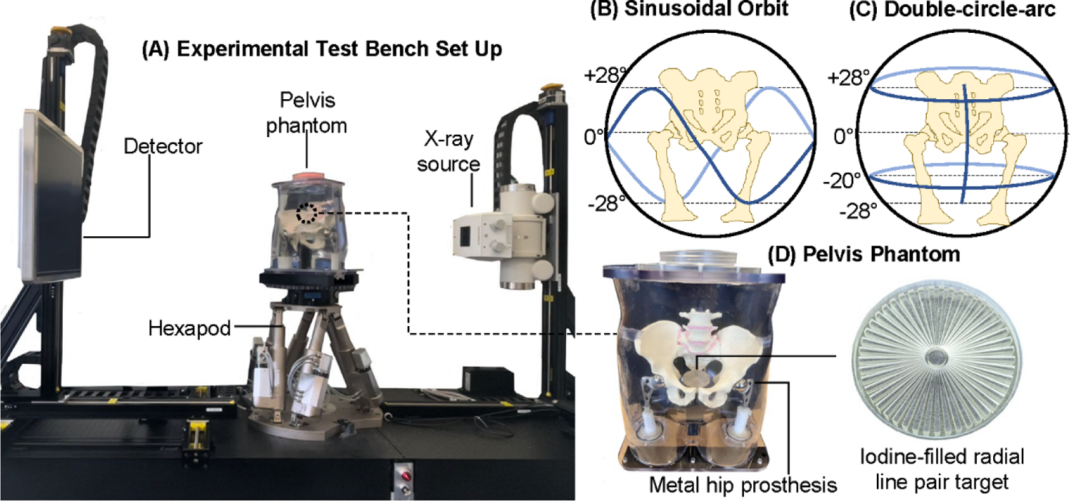
As a first proof-of-concept, orbits were implemented on a CBCT test bench with a fixed x-ray source (Varex Rad-94) and a flat panel detector (Varex PaxScan 4342CB). Gantry motion was simulated with a 6 degree-of-freedom motorized stage (PI H-900K Series) and a rotation stage (PI PRS-200), as shown in Figure 1 (A). All of the orbits were acquired in an automated “step-and-shoot” method through programming the movements of the motorized stage. The test bench scans were performed at 80 kV and 1.0 mAs per projection, with a source-to-detector distance of 1290 mm and a source-to-axis distance of 874 mm.
Figure 1.

(A) Experimental test bench set up, depictions of the (B) sinusoidal and (C) double-arc-circle orbits implemented on the test bench, and pelvis phantom with metal hip prostheses containing a radial line pair target.
2.2. Orbit Design
Two non-circular orbits were implemented. The sinusoidal orbit had a frequency f = 2, completing a 360° rotation around the phantom in the LAO/RAO direction while reaching a maximum tilt of ± 28° in the CRAN/CAUD direction, imaging every 1° of LAO/RAO rotation for a total of 360 projections [Figure 1 (B)]. The double-circle-arc orbit consisted of 2 × 360° circles at +28° and −20° CRAN/CAUD tilts, imaging every 2° for 180 projections per circle, and an arc from −28° to +28° in the CRAN/CAUD direction, imaging every 0.5° for 113 projections, resulting in a total of 473 projections [Figure 1 (C)]. A standard 360° circular orbit implemented with the test bench acted as comparator, imaging every 1° for a total of 360 projections.
2.3. Test Phantom
The imaging target was a physical pelvis phantom with two metal hip prostheses (Zimmer Biomet, Zimaloy – cobalt-chromium-molybdenum alloy), housing an iodine-filled radial line pair target (45 line-pairs, 60 mm diameter) situated in the axial plane of the prostheses [Figure 1 (D)].
2.4. Geometric Calibration
To achieve high-accuracy geometric calibration, we performed 3D-2D registration on the non-circular scans to reduce any geometric errors that might exist from the commanded robot positions9. First, the circular scan was reconstructed using an already calibrated geometry, and the volume was used as the registration target. Then, for each projection in the non-circular scans, the projection matrix that best matched the projected the registration target with the measured projection was iteratively found using the CMA-ES algorithm. The similarity metric was the gradient correlation.
2.5. Image Reconstruction
To best visualize the whole field-of-view and the high-resolution line-pair target while avoiding truncation artifacts and higher-than-necessary computation cost, we utilized a multiresolution model-based iterative reconstruction algorithm with a Penalized Weighted Least Squares (PWLS) objective and quadratic penalty10. For all experiments, 400 iterations of a separable paraboloidal surrogates (SPS) algorithm with 10 ordered subsets11 were applied. The sub-region surrounding the line-pair target was reconstructed with 0.25 mm3 isotropic voxels, while the remaining field-of-view was reconstructed with 0.75 mm3 isotropic voxels. To best showcase the effect of non-circular orbits, no additional metal artifact correction algorithms were applied.
3. RESULTS
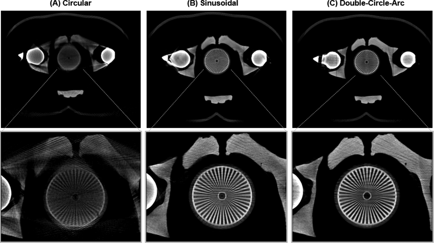
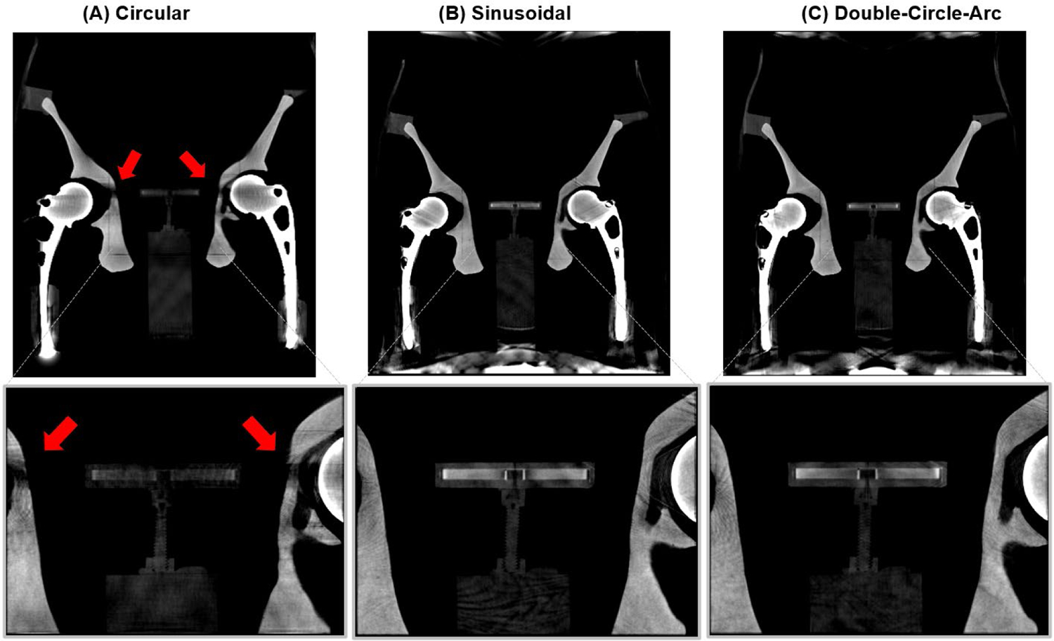
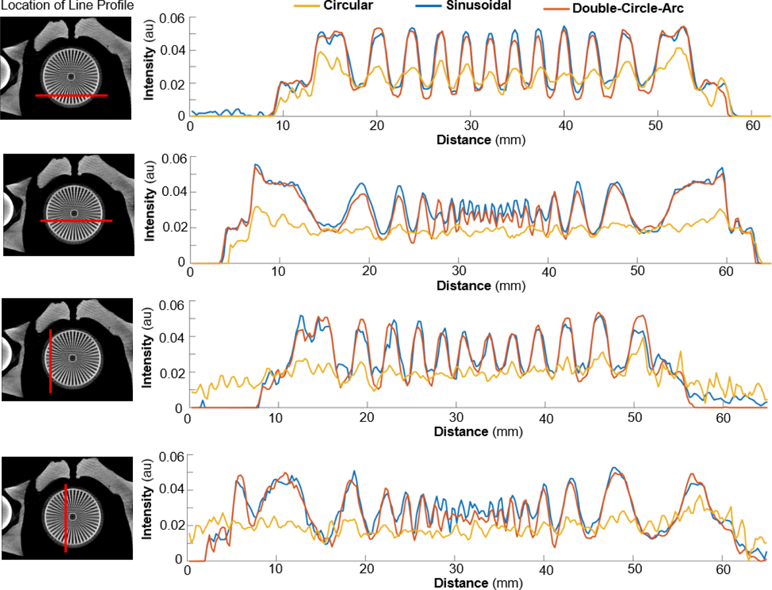
The multiresolution reconstructed 3D images (axial and coronal views) from the three orbits considered are provided in Figure 2 and 3 respectively. Examples of the linear-profiles across various regions of the line-pair targe from the three orbits considered are provided in Figure 4.
Figure 2.

Reconstructed images (axial view) of the pelvis phantom with two metal hip prosthesis housing the radial line-pair target acquired from (A) standard circular, (B) sinusoidal and (C) double-circle-arc orbits on a CBCT test bench. Intensity window display [0.048, 0.035] mm−1, 0.75 mm3 isotropic voxels. Insert shows close-up of high-resolution region reconstructed with 0.25 mm2 isotropic voxels.
Figure 3.

Reconstructed images (coronal view) of the pelvis phantom with two metal hip prosthesis housing the radial line-pair target acquired from (A) standard circular, (B) sinusoidal and (C) double-circle-arc orbits on a CBCT test bench. Intensity window display [0.048, 0.035] mm−1, 0.75 mm3 isotropic voxels. Insert shows close-up of high-resolution region reconstructed with 0.25 mm2 isotropic voxels.
Figure 4.

Linear profiles from 4 regions from standard circle (yellow), sinusoidal (blue) and double-circle-arc (red) orbits.
Imaging with the standard circular orbit, image artifacts can be observed in the pelvic bones (predominately in the axial and coronal views) and around and within the line-pair target (all views). Considering only the axial view, the 12 line-pairs residing in the central region in line with the hip prostheses are completely unresolvable. The remaining 33 line-pairs can be partially resolved, a minimum line-pair spacing resolution of 2.25 mm. Comparatively, imaging with both the sinusoidal and double-circle-arc orbits, the image artifacts near the pelvic bones have been significantly reduced, revealing the outline and structure of the bones in both the axial and coronal views. In all views, the artifacts around the line-pair target are also significantly reduced, with the thread on the screw securing the line-pair target to the pelvis phantom now visible. Considering the line-pair target in the axial view, both the sinusoidal and double-circle-arc orbits enable all 45 line-pairs to be visibly resolved, revealing the previously obscured structures. The sinusoidal orbit and double-circle-arc both had a minimum line-pair spacing resolution of 1.00 mm.
4. DISCUSSION AND CONCLUSION
This work presents the first investigation into applying non-circular orbits for imaging pelvic structures in the presence of metal hip prostheses. The CBCT test bench results demonstrate the ability of non-circular orbits to resolve small scale structures and eliminate image artefacts in surrounding anatomy arising from the metal hip prosthesis during standard circular orbits. The sinusoid and double-circle-arc orbits implemented in this study were selected based on their previously demonstrated performance, significantly reducing metal artifacts when imaging the spine in the presence of metal pedicle screws. Looking towards clinical translation of non-circular image acquisition, orbits such as the double-circle-arc are leading the way as they can be implemented on clinical C-arm systems without the need for additional control hardware or programming system positions. Future work includes increasing the anatomical complexity of the imaging target, implementing the orbit on clinical imaging hardware, as well as optimizing the orbit design specifically for avoiding the metal hip prostheses.
ACKNOWLEDGEMENTS
This research was supported, in part, by NIH Grant R01EB027127 and the Cancer Institute NSW Fellowship 2021/ECF1293. This work has not been submitted for publication or presentation elsewhere.
REFERENCES
- [1].Orth RC, Wallace MJ, and Kuo MD, “C-arm cone-beam CT: general principles and technical considerations for use in interventional radiology”, J. Vasc. Interv. Radiol, 19 (6), 2008. [DOI] [PubMed] [Google Scholar]
- [2].Bagla S, Rholl KS, Sterling KM, Breda A, Papadouris D, Cooper JM, and van Breda A, “Utility of cone-beam CT imaging in prostatic artery embolization” J. Vasc. Interv. Radiol, 24 (11), 2013. [DOI] [PubMed] [Google Scholar]
- [3].Myer E, Raupach R, Lell M, Schmidt B, and Kachelrieβ M, “Normalized metal artifact reduction (NMAR) in computed tomography” Med. Phys, 37 (10), 2010. [DOI] [PubMed] [Google Scholar]
- [4].Gang GJ, Russ T, Ma Y, Toennes C, Siewerdsen JH, Schad LR, and Stayman JW, “Metal-tolerant noncircular orbit design and implementation on robotic C-arm systems”, Conf. Proc. Int. Conf. Image Form. Xray. Comput. Tomogr 2020. [PMC free article] [PubMed] [Google Scholar]
- [5].Gang GJ and Stayman JW, “Universal orbit design for metal artifact elimination”, Phys Med Biol., 67(11), 2022. [DOI] [PMC free article] [PubMed] [Google Scholar]
- [6].Hatamikia S, Biguri A, Herl G, Kronkeif G, Reynolds T, Kettenbach J, Russ T, Tersol A, Maier A, Figl ML, Siewerdsen JH, and Stayman JW, “Source-detector trajectory optimization in cone-beam computed tomography: a comprehensive review on today’s state-of-the-art”, Phys. Med. Biol, 67 (16), 2022. [DOI] [PubMed] [Google Scholar]
- [7].Ma Y, Reynolds T, Gang GJ, Dillon O, Russ T, Wang W, Ehtiati T, Weiss C, Theodore N, Siewerdsen J, O’Brien R and Stayman JW, “Non-circular orbits on a clinical robotic c-arm for reducing metal artifacts in orthopedic interventions”, Med. Phys 48 (6) 2021 [Google Scholar]
- [8].Ma Y, Gang GJ, Ehtiati T, Reynolds T, Russ T, Wang W, Weiss C, Theodore N, Hong K, Siewerdsen JH, and Stayman JW, in Medical Imaging 2022: Image-guided procedures, robotic interventions, and modelling, San Diego, United States: 2022. [Google Scholar]
- [9].Ouadah S, Stayman JW, Gang G, Ehtiati T, and Siewerdsen JH, “Self-calibration of cone-beam CT geometry using 3D-2D image registration,” Phys. Med. Biol 61 2016. [DOI] [PMC free article] [PubMed] [Google Scholar]
- [10].Cao Q, Zbijewski W, Sisniega A, Yorkston J, Siewerdsen JH, and Stayman JW, “Multiresolution iterative reconstruction in high-resolution extremity cone-beam CT”, Phys. Med Biol 61 2016. [DOI] [PMC free article] [PubMed] [Google Scholar]
- [11].Erdogan H and Fessler JA, “Ordered subsets algorithms for transmission tomography” Phys. Med. Biol 44 1999 [DOI] [PubMed] [Google Scholar]


