

Summary
We report a simple droplet fluidic point-of-care test (POCT) that uses gravity to manipulate the sequence, timing, and motion of droplets on a surface. To fabricate this POCT, we first developed a surface coating toolbox of nine different coatings with three levels of wettability and three levels of slipperiness that can be independently tailored. We then fabricated a device that has interconnected fluidic elements—pumps, flow resistors and flow guides—on a highly slippery solid surface to precisely control the timing and sequence of motion of multiple droplets and their interactions on the surface. We then used this device to carry out a multi-step enzymatic assay of a clinically relevant analyte—lactate dehydrogenase (LDH)—to demonstrate the application of this technology for point-of-care diagnosis.
Graphical Abstract

INTRODUCTION
Point-of-care tests (POCTs) have democratized healthcare world-wide by enabling the rapid and accurate measurement of disease biomarkers by patients and care givers outside of a hospital setting. They are especially useful in resource-limited settings, where access to clinical laboratories is severely limited or non-existent1. Many POCTs require liquid to be moved across an interface. For example, the lateral flow assay (LFA)—the most widely used POCT—uses capillary flow to move reagents and analytes across a surface to carry out the assay. There are other, more complex diagnostic devices that use active microfluidics, which we define as the use of electrical power to actuate pumps, valves, and other microfluidic elements to carry out the assay2–5. In a different approach, the application of discrete voltages across spatially patterned microelectrodes is used to move droplets across adjacent spots by electrowetting6. While these technologies are powerful, they are also technologically complex, with attributes that run counter to the spirit of POCTs, which must be cheap, easy to fabricate, and must operate in diverse and operationally difficult environments without the need for electrical power. There is hence, in our view, a significant gap in the available technology to move droplets across a surface in a programmable way with a reproducibility that can match the performance of more sophisticated technologies.
We report herein a solution to this knowledge gap by demonstrating a rational surface engineering approach to manipulate the sequence, timing, and motion of droplets on a surface. This modular droplet fluidics platform controls the movement and interactions of discrete droplets across a surface solely by gravity and without the need for electrical power. Our development of the gravity driven droplet fluidics toolbox was motivated by the recognition that the emergence of surfaces with a wide range of hydrophobicity and slipperiness now provides an enormous opportunity to modulate the behavior of the liquid-solid interface7–11. This work was also inspired by the seminal work of Whitesides and coworkers on the uphill movement of liquid droplets on surfaces12, the work by Ismaigilov and coworkers on slip chips13–15, and by Prakash and coworkers on the passive manipulation of liquid droplets on surfaces16.
Our droplet fluidics platform is designed by encoding fluidic elements—liquid control functions—on to a highly slippery solid surface (i.e., a surface that displays high liquid mobility without the need for fluid-film lubrication) to enable precise control of the timing and sequence of the motion of multiple droplets and their interactions. The first step to fabricate the droplet fluidic elements was to develop a surface coating toolbox that enables local control of the slipperiness and wettability of solid slippery surfaces. The toolbox consists of nine different coatings with three levels of wettability and three levels of slipperiness that can be tailored independently. We then fabricated fluidic elements with different functions by microcontact printing appropriate coatings from the toolbox on to slippery solid surfaces. Finally, we combined several fluidic elements to create a POCT that carries out a multi-step enzymatic assay of a clinically relevant analyte—lactate dehydrogenase (LDH).
RESULTS AND DISCUSSION
Rational Design of the Fluidic Platform for Precise Control of Droplet Dynamics
Our approach to design a droplet fluidic platform to control and manipulate the movement of discrete droplets on a surface is based on exploiting water surface wettability and slipperiness in conjunction with gravity. This approach does not need any active elements, such as pumps or actuators and requires minimal auxiliary equipment—the only equipment we need is a mechanically operated holder to translate and rotate the device.
To control the movement of droplets, we first fabricated smooth slippery surfaces by activating the substrate—a glass slide—using an oxygen plasma, followed by covalently grafting short chain PEG at a high density on the surface to create a polymer brush (Figure 1a, Experimental Procedures and Supporting Text Section S1)7,11,17. These surfaces are highly slippery and thus display minimal adhesion to contacting aqueous liquid droplets. The negligible solid-liquid adhesion of this surface is characterized by a very low sliding angle —defined as the minimum tilt angle of a surface for a droplet to slide on it—and results in the nearly free sliding motion of aqueous droplets on the surface18,19. These surfaces can be categorized as hydrophilic (WL, contact angle 30° < θ < 60°), moderately hydrophobic (WM, 60° < θ < 90°), or hydrophobic (WB, 90° < θ < 130°).
Figure 1. Fabrication and characterization of droplet fluidic platform.

a) Fabrication steps of droplet fluidic devices: i) Activating a surface using oxygen plasma, ii) grafting PEG oligomers to the surface, iii) creating droplet pathways using a non-sticky acrylic layer, iv) enclosing the droplet pathway using a non-sticky lid. b) Snapshots of a device showing downward motion of droplets under gravity upon rotating the device around the horizontal axis. Background is shown in white, and blue represents non-sticky walls. No lid is attached for better visibility. Droplet volume is 30 μl. Also see Movie S1. c) Variation of sliding velocity of droplets by slipperiness on surfaces with different wettability, indicating the ability of patches to control the timing of motion of droplets. SH: highly slippery, SM: moderately slippery, SP: poorly slippery. d) Minimum required tilt angle for a droplet to overcome the capillary resistance at the surface (shown in white)-patch (shown in yellow) interface and slide down the surface. Three surface to patch combinations were tested. WH: hydrophilic, WM: moderately hydrophobic, WB: hydrophobic.
The coating of the substrate should be selected to ensure that its properties match the requirement of the liquids that will be in contact with the surface. For example, the slipperiness of the WL, WM, and WB surfaces are limited to liquids with a surface tension greater than 40 mN/m, 32 mN/m, and 17 mN/m, respectively (Supporting Text Section S2). Water has a surface tension of 72 mN/m, and aqueous buffers have a surface tension of ~69 mM/m, so that water and aqueous buffers should freely slide on these surfaces. Furthermore, the highly slippery hydrophilic surface could enable devices that incorporate this surface to operate in complex biological fluids such as serum, plasma, or blood20 due to its exceptional resistance to fouling, as seen by the lack of protein adsorption for four weeks (Supporting Text Section S2)7 11.
We controlled the path of droplets by attaching an acrylic sheet to the slippery surface with pathways that were laser-cut into the acrylic sheet, and glued a lid— a thin acrylic sheet—on top of the laser-cut acrylic sheet using double sided sticky tape to enclose the pathways (Figure 1a). The droplet pathway is designed to be wider than the droplet width , where is the minimum volume of a droplet that can slide on a surface and can be estimated using the Bond number criteria 21 where and are the density and the surface tension of the liquid, respectively and is the gravitational acceleration (see Supporting Text, Section S3 for details). We functionalized the walls and lids of the channels using fluorinated silica particles to render them superomniphobic—non-sticky to all liquids22,23—to ensure that all liquids can slide within the pathways without adhering to the solid surfaces24–26 (see Experimental Procedures and Supporting Text, Section S1 for details).
We designed the droplet fluidic platform such that that upon rotating it around the horizontal axis, droplets slide down the surface due to gravity, which provides the driving force for the droplets to move, where is the density of the liquid, is the volume of the droplet, and is the tilt angle of the solid surface27. The geometry of the pathway offers the first level of control of droplet motion as seen by the design of the geometric features embedded in the figure DUKE in Figure 1b (and Movie S1): shows the precise control of the path of droplets in their downward motion (i.e., they do not cross the borders demarcated by the letter D ); shows the ability to precisely control the droplet velocity—the velocity is higher in the narrower channel); shows the ability to program the timing of the interactions of droplets, as shown by the fusion of the droplets when they reach the junction; shows the ability to program the sequence of motion and interactions of two droplets, as seen by the stationary droplet on the horizontal path that waits for the droplet sliding down the vertical path and then merges with it when contacted by the sliding droplet.
The second level of precise spatiotemporal control of the sliding of droplets is achieved by embedding distinct chemical features in the fluidic pathways. To do so, we developed a “Coating Toolbox” (Table 1, see Experimental Procedures and Supporting Text Section S1) that consists of nine functionally distinct coatings. Surfaces that are already activated using oxygen plasma are chemically modified (in 0.5 to 3 hours) to tune their wettability and slipperiness. All chemicals (e.g., silanes and solvents) that are required to modify the surfaces are commercially available (Experimental Procedures and Supporting Text Section S1). We categorized the coatings at three levels of wettability (i.e., WL: hydrophilic 30° < θ < 60°, WM: moderately hydrophobic 60° < θ < 90°, and WB: hydrophobic 90° < θ < 130°) and three levels of slipperiness (i.e., SH: highly slippery ω < 20°, SM: moderately slippery 20° < ω < 40°, and SP: poorly slippery 40° < ω < 60°, Supporting Text Section S2). To the best of our knowledge, this is the first report of the systematic—and independent—tuning of the wettability and slipperiness of solid surfaces.
Table 1.
Coatings Toolbox, See Supporting Text Section S2 for more details.
| Wettability | Slipperiness | ||
|---|---|---|---|
| Highly Slippery | Moderately Slippery | Poorly Slippery | |
| Hydrophilic 30° < θ < 60° | WL-SH | WL-SM | WL-SP |
| Moderately HB 60° < θ < 90° | WM-SH | WM-SM | WM-SP |
| Hydrophobic 90° < θ < 130° | WB-SH | WB-SM | WB-SP |
To control the movement of droplets in the fluidic pathway, we fabricated a patch in the droplet path (shown in yellow in Figure 1d inset, Supporting Text Section S3) with coatings of different wettability and/or slipperiness from the Toolbox using a masked microcontact printing technique10. This patch is designed to function in various ways. First, the patch can apply a frictional force to a sliding droplet that can decelerate its motion. The reduction in the sliding velocity of the droplet enables control of the timing of the motion of droplets on the surface.
Second, applying a capillary force to the droplet due to the wettability contrast at the surface-patch interface can stop a droplet. In one embodiment of this concept, a hydrophilic highly slippery (i.e., WL-SH) surface is coated with a more hydrophobic highly slippery (i.e., WM-SH or WB-SH) patch (Figure 1d inset). If a droplet slides on the hydrophilic surface, at the interface of the hydrophilic surface and the more hydrophobic patch, a capillary force is applied to the droplet that can obstruct its motion (if ), until an increase in the droplet driving force (by increasing the tilt angle of the surface ) enables the droplet to resume its motion.
Temporal obstruction of droplets using patches with different hydrophobicity enables control of the sequence of the motion of droplets. In the simplest embodiment of this concept, a Y-shaped WL surface has a WM patch in one arm and a WB patch in the other arm, and two droplets are sliding down each arm of the WL surface and reach the WM and WB patches and stop (see Supporting Text, Section S3–2 for details). Upon tilting the surface, at a critical angle, the droplet trapped at the WM patch crosses the WM patch while the other droplet is still obstructed by the WB patch because of its greater hydrophobicity. If we continue increasing the tilt angle, at a larger critical angle, the second droplet will cross the WB patch and will chase the first droplet down the stem of the Y-shaped path.
Conversely, if the droplet is introduced on a hydrophobic patch and slides down, at the interface of the hydrophobic patch and the hydrophilic surface, the capillary force suctions the droplet toward the hydrophilic zone, thereby increases its kinetic energy and accelerates the droplet. Such local increase in the sliding velocity of a droplet that is induced due to the wettability contrast between the patch and the surface enables control of the timing of the motion of droplets on the surface. This is because modulating the wettability contrast between the patch and surface modulates the capillary force applied to the droplet, which then controls the acceleration of the droplet and thereby controls the time when the droplet reaches a specified spot in the path.
We next characterized the variation in the velocity of droplets sliding past patches with different wettability and slipperiness (Figure 1c, Supporting Text, Section S2). Our results show a significant reduction in the sliding velocity of droplets by reducing the slipperiness of surfaces. This reduced velocity results in a significantly longer sliding time, which can be exploited to control the timing of the motion of droplets on a surface. We also characterized the capillary force applied to droplets at the patch-surface interface for the following combinations: i) hydrophilic surface to hydrophobic patch (WL to WB), ii) hydrophilic surface to moderately hydrophobic patch (WL to WM), and iii) moderately hydrophobic surface to hydrophobic patch (WM to WB). To do so, we placed a 30 μL droplet of deionized (DI) water on a horizontally mounted surface and gradually rotated the surface. The droplet started to slide at its minimum tilt angle (sliding angle is specified in Table S1) and reached the surface-patch interface where its motion was obstructed due to the capillary resistance caused by wettability contrast. Then we increased the tilt angle until the droplet resumed its sliding motion down the patch (i.e., critical tilt angle ). At the critical tilt angle , the capillary force (which is against the droplet motion here), is balanced by the gravitational force (i.e., ).
Figure 1d shows the variation of by increasing the droplet volume at different surface-patch interface combinations. Our results show that increasing the wettability contrast results in an increase in the minimum droplet volume () required to overcome the capillary force. According to Furmidge’s equation27 the adhesion force applied to a droplet when it slides on a solid surface is proportional to the surface tension and width of the droplet as well as the difference between the advancing and receding contact angles of the droplet on the surface. When a droplet crosses a surface-patch interface, it adopts the advancing contact angle at the edge close to the patch and the receding contact angle at the edge away from the patch. Hence, we postulate that the capillary force () at the surface-patch interface can be stated as:
| (1) |
where is the surface tension of the liquid, is the diameter of the droplet’s footprint on the surface and and are the receding and advancing contact angles of the droplet on the surface and patch, respectively.
Our results indicate that the estimated is reasonably matched to the gravitational force at the onset of passing the surface-patch interface (Figure S1). If a droplet slides on the surface in the reverse direction (i.e., slides on the patch and approaches the patch-surface interface), the magnitude of the capillary force can be estimated using equation 1, though this causes local acceleration of the droplet rather than obstruction, Increasing the wettability contrast between the surface and the patch increases the capillary force at the surface-patch interface (Figure S1) that can be used to modulate droplet motion.
Passive Fluidic Elements Implemented by Surface Design
The coatings in the Toolbox enable us to locally alter the droplet sliding velocity by applying a frictional force when the droplet passes the patch or to temporarily obstruct or accelerate the droplet motion by applying a capillary force at the surface-patch interface. Combining these effects, we hypothesized that we could precisely control the sequence and timing of the motion of droplets and their interactions. To do so, we utilized the coatings of our Toolbox to generate a set of passive “fluidic elements” such as a flow resistor, reservoir, stop valve, trigger valve, flow guide and flow pump that are functionally analogous to the “active” components in conventional microfluidic systems that consume power to actuate these components (Figure 2 and Movie S2).
Figure 2. Snapshots of droplets sliding over fluidic elements.

a) Flow resistor to locally decelerate a droplet and increase its sliding time. b) Reservoir to collect droplets. c) Stop valve to obstruct droplets sliding. d) Trigger valve to control the timing, release, and mixing of droplets. e) Flow guide to control the direction of droplets at surface-patch junctions. f) Flow pump to accelerate a droplet and reduce its sliding time or to remove stagnant droplets (green droplet). All droplets were dyed with different colored food dyes for easy visualization. The surface and patches are shown in white and yellow (or orange due to lighting effect), respectively and blue represents non-sticky walls of paths. Colors are introduced using colored tapes that were attached to the back of the glass slides. Droplet volume is 30 μl (Also see Movie S2).
The fluidic elements are fabricated as described in the text that accompanies Figure 1a. Briefly, we: (1) fabricate a highly slippery surface as described in the Experimental Procedures and Supporting Text Section S1, (2) draw the shape of the path and location of the patch at the back side of the slide, (3) apply the hydrophobic patch (except hydrophilic patch in Figure 2b) to the slippery surface, (4) coat the surrounding of the path (blue regions) with a super-omniphobic coating, (5) erase the marked shape of the path on back side of the slide, (6) and attach colored tapes (blue, white and yellow) to enable easy visualization of the different fluidic elements. These fluidic elements in Figure 2 did not have an acrylic lid to enclose the fluid path.
After fabrication of each fluidic element, experiments to demonstrate their function were carried out as follows: the slide was placed on an inclined surface at a fixed angle of 45° (Figure 2a–e) or 15° (Figure 2f). Next, droplets were added to the surface and allowed to slide down due to gravity. To visualize the fluid path and fluidic elements, we attached colored tapes (blue, white, and yellow) on the back side of the slide. Note that yellow regions look orange in some cases due to lighting effects. All experiments corresponding to Figures 2a–f are combined in a single movie (Movie S2) in the Supplementary information to enable visualization of the function of each fluidic element.
The Flow Resistor locally decelerates a droplet when it is sliding over the patch and thus increases its sliding time (Figure 2a). The flow resistor consists of a hydrophilic highly slippery (WL-SH) surface overlaid with a hydrophilic moderately slippery (WL-SM) patch. The lower slipperiness of the patch results in a higher frictional force (see Figure 1c) that lowers the sliding velocity, leading to a longer sliding time over the patch. The similar wettability of the surface and the patch ensures negligible capillary force (resistance) at the surface-patch interface (Figure 1d), so that droplets are smoothly transferred from the surface to the patch. Any combination of coatings in Table 1 with similar wettability and different slipperiness (i.e., less slippery patch) can be used to make a flow resistor and will yield different levels of deceleration depending on the combination of wettability and slipperiness that is chosen.
The Reservoir collects droplets over the patch (Figure 2b). It consists of a hydrophilic highly slippery (WL-SH) surface with a hydrophilic poorly slippery (WL-SP) patch. The poor slipperiness of the patch results in significantly higher frictional force (see Figure 1c) that ends up in a nearly zero sliding velocity over the patch. A rapid change in the sliding velocity of a droplet transferring from the surface to the patch also facilitates mixing of droplets (Figure S2). The similar wettability of the surface and the patch ensures smooth transfer of droplets from the surface to the patch. Different combination of coatings in Table 1 with similar wettability and different slipperiness can be used to make a reservoir.
The Stop Valve obstructs a droplet when it approaches the surface-patch interface (Figure 2c). It consists of a hydrophilic highly slippery (WL-SH) surface with a hydrophobic (WB) patch. The wettability contrast between the surface (here WL) and the patch (here WB) results in a capillary force (see equation 1, Figure S1) that obstructs the droplet at the surface-patch interface. Increasing the volume of the first droplet — a second droplet flow down and fuses with the first stationary droplet — cannot overcome the capillary resistance force at the surface-patch interface until (Figure 1d).
The Trigger Valve obstructs a droplet at a surface-patch interface and controls its release time and mixing with other droplets (Figure 2d). It consists of a hydrophilic highly slippery (WL-SH) surface overlaid with a hydrophobic highly slippery (WB-SH) patch. The wettability contrast between the surface (here WL) and the patch (here WB) results in a capillary resistant force (see equation 1, and Figure S1) that temporarily obstructs the droplet (shown in green) at the surface-patch interface. Upon contacting the second droplet sliding down the patch (shown in red) with the stagnant droplet, the stagnant droplet is suctioned into the patch and mixes with the second droplet along its path.
The Flow Guide controls the direction of motion of a droplet at a surface-patch interface (Figure 2e). It consists of a hydrophilic highly slippery (WL-SH) surface overlaid with a hydrophobic (WB-SH) patch. The wettability contrast between the surface (here WL) and the patch (here WB) results in a capillary resistant force (see equation 1, Figure S1) that can be exploited to control the direction of droplets sliding toward the surface-patch interface. Other geometry-based flow guides that controls the direction of motion of a droplet can also be designed (see Movie S2).
The Flow Pump accelerates a droplet and thereby reduces its sliding time when the droplet approaches the interface (Figure 2f). It consists of a hydrophilic highly slippery (WL-SH) surface overlaid with a hydrophobic highly slippery (WB-SH) patch. The wettability contrast between the highly slippery and hydrophilic WL surface and the highly slippery hydrophobic WB patch results in a capillary force (see equation 1) that provides rapid suction of the droplet from the patch toward the surface at the surface-patch interface. As a droplet is suctioned from the hydrophobic patch to the hydrophilic surface, it expands (see Supporting Text, Section S2–5 for details) which requires a wider pathway to minimize contact between the droplet and the wall. The local increase in the kinetic energy of a droplet can be exploited to remove—sweep away—stagnant droplets from the flow path (green droplet in Figure 2f) or to improve mixing with other droplets along its path.
Other combination of the coatings in Table 1 with different wettability can be used to make these fluidic elements such as stop valves, trigger valves, flow guides, or flow pumps, and the choice of the precise surfaces chosen from each category will define their performance metrics. We also combined multiple fluidic elements on more complicated channels with several pathways to fabricate multiplexed fluidic controls, such as a release delayer (to keep a droplet in place and release it with a delay), a mixer, and a reactor (Supporting Text Section S3).
Design of a Droplet Fluidic POCT
With these passive droplet fluidic elements in hand, we next sought to rationally combine several elements to demonstrate proof-of-principle of the utility of this technology. We developed an enzymatic POCT that requires sequential reactions, because multi-step reactions are not easy to implement in a POCT, especially without the use of active elements. We chose the measurement of lactate dehydrogenase (LDH) in human serum, given its clinical utility as a biomarker for thrombosis in patients receiving implants28. LDH can be measured enzymatically by monitoring the conversion of nitroblue tetrazolium (NBT) to formazan, a reaction that is coupled to the LDH concentration by a chain reaction that depends on the oxidation of methylphenazinium methyl sulfate (mPMS)29 (Figure 3a and Movie S3). An increase in the LDH concentration results in an increase in the rate of NADH formation, which results in a color change. To accurately measure LDH concentration, the mixing of reagents in solution plays a key role, which was a critical consideration in our design of the droplet fluidic POCT.
Figure 3. Droplet fluidic POCT to measure LDH concentration.
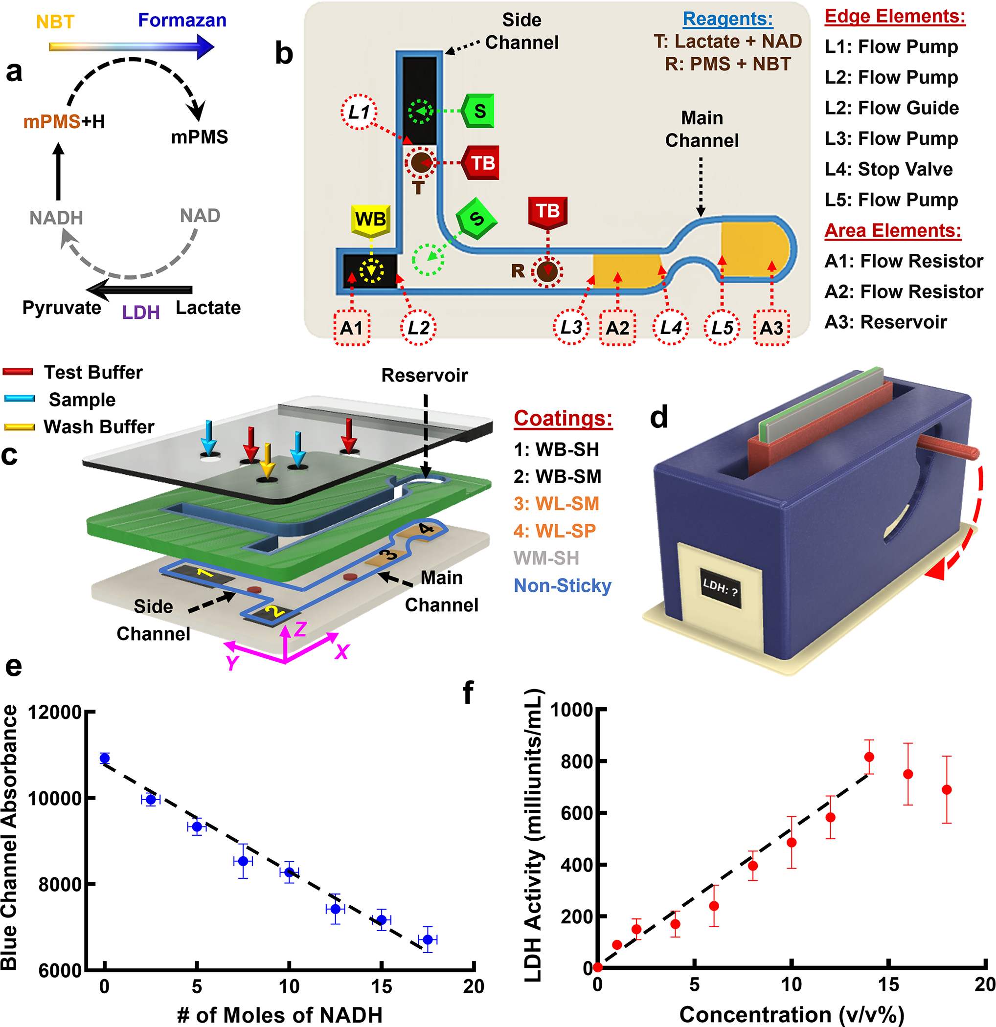
a) Schematic showing the basis of the enzymatic reaction used in the POCT. The presence of LDH increases the rate of the enzymatic reaction which results in a rapid color change to dark blue. b) Layout of the droplet fluidic elements in the POCT. Hydrophobic and hydrophilic patches are shown in black and orange, respectively. Reagent T (Lactate + NAD) and R (PMS + NBT) are dried on the surface (shown in brown) and are dissolved upon exposure to test buffer droplets. Position of sample droplet (S), test buffer droplet (TB) and wash buffer droplet (WB) are shown as circles with dashed lines. c) Exploded view of the POCT components that show the glass slide, an acrylic layer with laser-cut pathways and an acrylic lid with holes to introduce S, TB, and WB droplets. The glass slide is modified with a WM-SH coating (shown in gray) and the intermediate acrylic layer and acrylic lid are modified to be super-omniphobic. The WB-SH patch (#1) and WB-SM patch (#2) are shown in black, and the WL-SM patch (#3) and WB-SP patch (#4) are shown in orange. Positions of holes in the lid to introduce test buffer droplets (shown in red), sample droplets (shown in blue) and wash buffer droplets (shown in yellow) are illustrated. d) The POCT is inserted into a portable colorimetric detector with a rotating slot to carry out the assay for LDH measurement. Upon inserting the POCT in the rotating slot of the detector and upon rotating the handle all the way down, the detector measures the intensity of the blue color in the test solution as a function of time to estimate the LDH concentration of the solution. e) Change in the Blue Channel Absorbance at ~465 nm as a function of the # of moles of NADH f) Dose-response curve for LDH in LDH Positive Control Standard solution from Sigma diluted into buffer (see Supporting Text Section S4).
We designed and fabricated a two-channel droplet fluidic device for the quantification of LDH concentration in serum (Figure 3b and 3c). The design of the cassette to carry out the POC assay has reagents that are printed as discrete spots on the bottom surface of the cassette—the glass slide—and several fluidic elements printed onto this surface that mix the sample with dissolved reagents, time the movement of the liquid in the cassette to provide the necessary incubation time, and then carry the product to the reservoir, where the blue product generated by the reaction is detected by a colorimetric detector that we custom-built for this purpose.
The fabrication of the device involves the following steps. We first modified the surface of a glass slide with a WM-SH coating to be moderately hydrophobic and highly slippery (shown in grey in Figure 3b). Next, the following fluidic elements were incorporated in the channels by masked microcontact printing using the coatings listed in Figure 3c.
Element L1 is a flow pump in the side channel fabricated by microcontact printing a WB-SH coating on glass slide that is already modified to be with WM-SH. The L1 pump is formed at the boundary of the WB-SH coating and the underlying WM-SH coating. The flow pump mixes the droplet of the sample (S) in the vertical side channel with the T droplet (a dissolvable droplet of lactate + NAD) and ensures dissolution and transfer of the T droplet down the vertical flow path.
Element A1 is a flow resistor in the main channel fabricated as a patch of a WB-SM coating whose function is to decelerate the wash buffer droplet (shown by the yellow dashed circle on element A1 in Figure 3b and by the yellow arrow in Figure 3c), and thereby provide a time lag in releasing the wash buffer to the main channel (see Delayed Release, Supporting Text Section S4), compared to the other solution droplet sliding down the main channel.
Element L2 is a flow pump in the main channel fabricated at the interface of a WB-SM patch and the slippery glass slide whose function is to add kinetic energy to the wash buffer droplet at the onset of its release to the main channel. Element L2 facilitates the transfer of liquid from left to right—the more hydrophobic to less hydrophobic zone (Figure 3b), while preventing liquid transfer in the reverse direction. The combination of the flow resistor (Element A1) and the flow pump (Element L2) provides a complete—albeit delayed—transfer of the wash buffer to the main channel with no residue left behind.
Element L2 also functions as a flow guide at the junction of the side and main channels that guides the solution sliding down the side channel to the right leg of the main channel.
Element L3 is a flow pump in the main channel fabricated at the interface of the slippery glass slide and a patch of a WL-SM coating that accelerates liquid (i.e., the mixture of sample and test buffer, or the wash buffer) and thereby provides suction to move solution to the right.
Element A2 is a flow resistor in the main channel fabricated from a WL-SM coating that decelerates the liquid (i.e., the mixture of sample and test buffer, or the wash buffer) close to the solid-liquid interface. The sample droplet and test buffer droplet sliding down the side channel are mixed with the sample + test buffer in the main channel and reach the L3 and then A2 elements. With a delay, the wash buffer droplet sliding down the main channel reaches the E3 and A2 elements.
Element L4 is a stop valve in the main channel fabricated at the interface of the WL-SM patch and the slippery glass slide that facilitates mixing by temporarily obstructing the motion of the liquid. The formation of a large droplet is necessary to overcome the capillary resistance and to enable crossing the valve. A velocity increase due to the flow pump (Element L3) followed by rapid velocity reduction over the flow resistor (Element A2) and then due to the stop valve (Element L4) pushes the liquid out from the slippery glass slide and drives strong circulation of liquid in the x-z plane (Figure S5) that significantly improves mixing of the liquids (see Mixer in Supporting Text Section S4 for additional details).
Element L5 is a flow pump in the main channel fabricated at the interface of the slippery glass slide and the WL-SP coating that increases the velocity of liquid entering the reservoir.
Element A3 is a reservoir fabricated from a WL-SP coating that reduces the velocity of liquid near the surface and thereby improves solution mixing within the reservoir before detection (see Mixer in Supporting Text Section S4 for additional details).
Following printing of all the fluidic elements, two 4 μL droplets of “Lactate + NAD” and “PMS + NBT” were placed and dried on trehalose excipient pads on spots T and R (shown as brown circles in Figures 3b and 3c) in the side and main channels, respectively (Supporting Text Section S4). The trehalose pad enables dissolution of the reagents upon exposure to buffer. An intermediate non-sticky acrylic layer is then bonded to the bottom surface that creates the channel for movement of liquid and a non-sticky top lid is then bonded to this intermediate layer that has ports where sample, dissolution buffer and wash buffer can be added (see Supporting Text Section S4 for additional details).
To carry out the assay, the colorimetric detector (Figure 3d) is turned on to allow it to stabilize. Then, two 30 μL droplets of the test buffer (TB) are pipetted on spots R and T, two 60 μL droplets of sample (S, human serum) are pipetted on spots S, and a 60 μL droplet of wash buffer (WB) is pipetted on the spot WB of the device (Figure 3c and Figure S5). After incubation for 15 min, which dissolves the dried reagents on the R and T spots, the cassette is inserted into the detector (Figure 3d), making sure the reservoir is facing down.
Inserting the cassette in the vertical slot of the detector entails rotating the device 90° about the x axis and mounting it in the XZ plane (see Figure 3c) so that the side channel of the device will be mounted vertically downward. This enables the S and TB droplets in the side-channel to slide down the surface, while the acceleration induced in the S droplet due to the L1 flow pump combined with the higher gravitational force (due to the larger volume of S droplet) ensures mixing of the S and TB droplets. The solution composed of S+TB droplets slide down the side-channel and mix with the second S droplet at the junction of side and main channels, while the L2 flow guide prevents them from contacting the WB droplet. Upon rotating the handle of the detector all the way down (see Figure 3d), the cassette will be rotated 90° about the Y axis (i.e., the A1 flow resistor will be on top and A3 reservoir will be at the bottom, see Figure 3c). This enables the S+TB+S solution to slide down the main channel and mix with the second TB droplet, while the WB droplet is released with a time lag due to the A1 flow resistor (delayed release, see Supporting Text Section S3–2). Once the WB droplet is released to the WM-SH path, the L2 flow pump increases the kinetic energy of the droplet to sweep away residue from the S+TB+S+TB solution. The presence of a mixer (L3+A2+L4, see Supporting Text Section S3–2) and the geometrical curvature of the non-sticky walls after the mixer improves the mixing of the S+TB+S+TB solution before entering the reservoir. Increased acceleration due to the L5 flow pump followed by the poor slipperiness of the A3 patch results in further mixing of the solution in the reservoir.
The enzymatic reaction (Figure 3a) results in a blue solution in the reservoir and the rate of change of the color intensity with time is a function of the rate of the reaction, which is a function of the LDH concentration in the sample. Upon addition of the WB to the reservoir, the detector records the rate of color change in the solution for ~15 min and estimates the LDH concentration. Details of the design and fabrication of the colorimetric detector and associated software are in Supporting Text Section S4.
We developed the POC device for direct analysis of LDH in complex biological samples (here human serum). Similar to the conventional method of colorimetric measurement of LDH concentration, we added different concentrations of NADH (i.e., number of moles of NADH) to the buffer and measured the blue channel absorbance (Figure 3e, Supporting Text Section S4). This enables us to correlate the NADH concentration with the intensity of the blue color, and thereby calculate the LDH level in any test sample) by the formula 30. Here is the number of moles of NADH produced in the test sample within a time frame (Figure 3e), is the total volume of the test solution collected in the reservoir and is a correction factor that is calculated by comparison of the linear regime of the dynamic range of LDH measurement using the droplet fluidic POCT and a standard commercial LDH measurement kit30. We estimated the dynamic range of a standard commercial LDH measurement kit30 using Sigma LDH Positive Control Standard of different dilutions (Figure S9–b, see Supporting Text Section S4 for more details). Similarly, we measured the LDH level of similarly diluted Sigma LDH Positive Control Standard using the droplet fluidic POCT and calculated the correction factor “K” by calculating the ratio of the slopes in the linear region of the dynamic range of the dose-response curve and the results in Figure S9–b assuming a y-intercept of 0 for both. Figure 3f Dose-response curve for Sigma LDH Positive Control Standard diluted in Tris buffer.
Our results show that when the concentration of the positive control in test solution is >15%, the homogeneity of the solutions in the reservoirs were significantly altered which resulted in inaccurate LDH level estimation. However, this does not limit the utility of our device, as the normal LDH level in human is less than 450 Units/L, which corresponds to a concentration of ~8.5% [29]. After determining the value of the correction factor K of 1.0961, we measured the LDH level in human serum (89±6) which shows good agreement with the value measured by a commercial LDH measurement kit (96±2).
CONCLUSION
We have described herein a rational surface engineering strategy to encode diverse droplet manipulation functions onto a solid surface. We did so by creating a comprehensive set of polymer surface coatings with a range of water slipperiness and wettability and used these coatings to spatially pattern a surface with specific combinations of these coatings to fabricate different fluidic control elements on a surface to control the motion of aqueous droplets solely by gravity. These droplet fluidic control elements include a flow resistor, reservoir, stop valve, trigger valve, flow guide and flow pump. We combined some of these fluidic elements on a slippery surface to demonstrate the precise gravity-driven manipulation of droplets that allows droplets to be stopped, sped up, slowed down, fused, and their direction of motion manipulated at will.
The stability of polymer surfaces in different environmental and experimental conditions11 makes them appropriate for a wide range of applications. To demonstrate proof-of-principle of the utility of this technology, we combined several fluidic elements in the flow path of a cassette with dissolvable reagents in the cassette and ports for the addition of the sample and buffers to fabricate a POCT for the detection of LDH. Operation of the assay only requires addition of droplets of the sample and two aqueous buffers at specific ports, insertion of the cassette into the detector, and translation of the cassette in the XZ plane by rotation of a lever that is built into the housing of the detector. The detector monitors the rate of change in the intensity of the blue color of the solution to estimate the LDH concentration in the solution.
The coatings toolbox and the modular droplet fluidic elements reported here provide a new capability to manipulate discrete droplets on solid surfaces without the need for mechanical components, pumps, or a power supply. We believe that the passive droplet fluidics technology demonstrated herein has significant utility for the design of POCTs, such as serology-based assays using other detection methods (e.g., fluorescence or electrochemistry-based assays). More broadly, it may prove useful for the development of diverse bioanalytical systems and across many areas of chemistry and materials science that can benefit by control of the movement and interactions of discrete microliter volume droplets on a solid surface.
Experimental Procedures
• Resource availability
Lead contact: chilkoti@duke.edu
Inquiries regarding the data and resources associated with this paper be directed to Prof. Ashutosh Chilkoti (Chilkoti@duke.edu).
• Materials availability
Requests of materials can be directed to Prof. Ashutosh Chilkoti (Chilkoti@duke.edu).
• Data and code availability
Inquiries regarding the data and resources associated with this paper be directed to Prof. Ashutosh Chilkoti (Chilkoti@duke.edu).
Fabrication of All-Solid Smooth Slippery Surfaces
Microscope glass slides (Nexterion) were cleaned by sonication in acetone and ethanol, rinsed with DI water, and dried with nitrogen. Cleaned glass slides were exposed to oxygen plasma (Electro-Technic Products, BD-20) for > 2 min to be ready for the final surface modification as:
Hydrophilic, highly slippery (WL-SH): A glass slide is immersed in a solution consisting of 2-[(acetoxy(polyethyleneoxy)propyl]triethoxysilane, 95% (SIA0078.0, Gelest Inc) and concentrated hydrochloric acid (36%) in anhydrous toluene ratio of 1:1:1000 by volume (e.g., 40 μL silane, 40 μL acid, 40 mL toluene) for 30 min ~ 5 h at room temperature. Finally, the modified surfaces were rinsed thoroughly with toluene and DI water, dried with pressurized nitrogen, and stored in a desiccator for future use.
Moderately hydrophobic, highly slippery (WM-SH): A glass slide was submerged in a solution consisting of 3-cyanopropyldimethylchlorosilane (SIC2452, Gelest Inc) and concentrated hydrochloric acid (36%) in anhydrous hexane 95% ratio of 1000:1:1000 by volume for 1 min and withdrawn gradually. The substrate was allowed to dry for 2 h at room temperature. Finally, the modified surfaces were rinsed thoroughly with DI water, dried with pressurized nitrogen, and stored in a desiccator for future use.
Hydrophobic, highly slippery (WB-SH): A glass slide was submerged in a solution consisting of dimethyldimethoxysilane 99% (SID4123.1, Gelest Inc) and sulfuric acid in isopropanol ratio 10:1:100 by volume (mixed for 15 min to be ready) and withdrawn gradually. Excess solution was drained by brief contact with filter paper. The substrate was allowed to dry for 30 min at room temperature. Finally, the modified surfaces were rinsed thoroughly with Isopropanol and then DI water, dried with pressurized nitrogen, and stored in a desiccator for future use17.
Fabrication of Super-omniphobic (Non-Sticky) Surfaces
As described in detail elsewhere22,23, fumed silica particles (400 mg of 7 nm, Sigma-Aldrich) were dispersed in a solution consisting of heptadecafluoro-1,1,2,2-tetrahydrodecyl trichlorosilane (0.6 mL, Gelest) and hexane (10 mL) ratio 6:100 by volume. The sealed glass vial was placed on a shaker at room temperature for three days to obtain a suspension of fluorinated fumed silica particles. A polyurethane-based adhesive (Gorilla Glue, Inc.), diluted with acetone, was spin-coated on a cleaned glass slide (using a Paasche air brush) followed by spin coating the suspension of fluorinated fumed silica particles. Finally, the modified surface was stored at room temperature for 2 h to ensure the complete curing of the adhesive layer.
Developing the Coating Toolbox
Fabrication processes of the coatings listed in our Coating Toolbox (Table 1) are provided in Table S1, (Supporting Text, Section S1). In all cases, pre-activation of surfaces using Oxygen plasma (> 2 min) is required. Volume ratio of the silanes and solvents is 1:1, unless otherwise noted. Coatings are implemented through micro-contact printing9 technique using a lint-free tissue (with excess solution).
Supplementary Material
Movie S1. Unique Features of the Fluidic Device.
Movie S3. LDH Measurement System.
Movie S2. Fluidic Elements.
Inclusion and Diversity
We support inclusive, diverse and equitable conduct of research.
Footnotes
Declaration of Interests
The authors declare no conflict of interests.
References
- 1.Kelley SO, Mirkin CA, Walt DR, Ismagilov RF, Toner M, and Sargent EH (2014). Advancing the speed, sensitivity and accuracy of biomolecular detection using multi-length-scale engineering. Nature Nanotechnology 9, 969–980. 10.1038/nnano.2014.261. [DOI] [PMC free article] [PubMed] [Google Scholar]
- 2.Li Z, Bai Y, You M, Hu J, Yao C, Cao L, and Xu F (2021). Fully integrated microfluidic devices for qualitative, quantitative and digital nucleic acids testing at point of care. Biosensors and Bioelectronics 177, 112952. 10.1016/j.bios.2020.112952. [DOI] [PMC free article] [PubMed] [Google Scholar]
- 3.Chin CD, Linder V, and Sia SK (2012). Commercialization of microfluidic point-of-care diagnostic devices. Lab on a Chip 12, 2118–2134. 10.1039/C2LC21204H. [DOI] [PubMed] [Google Scholar]
- 4.Dai Y, and Liu CC (2019). Recent Advances on Electrochemical Biosensing Strategies toward Universal Point-of-Care Systems. Angewandte Chemie International Edition 58, 12355–12368. 10.1002/anie.201901879. [DOI] [PubMed] [Google Scholar]
- 5.Zhang Y, Zhu H, Ying Z, Gao X, Chen W, Zhan Y, Feng L, Liu CC, and Dai Y (2022). Design and Application of Metal Organic Framework ZIF-90-ZnO-MoS2 Nanohybrid for an Integrated Electrochemical Liquid Biopsy. Nano Letters 22, 6833–6840. 10.1021/acs.nanolett.2c01613. [DOI] [PubMed] [Google Scholar]
- 6.Fair RB (2007). Digital microfluidics: is a true lab-on-a-chip possible? Microfluidics and Nanofluidics 3, 245–281. 10.1007/s10404-007-0161-8. [DOI] [Google Scholar]
- 7.Cha H, Vahabi H, Wu A, Chavan S, Kim M-K, Sett S, Bosch SA, Wang W, Kota AK, and Miljkovic N (2020). Dropwise condensation on solid hydrophilic surfaces. Science Advances 6, eaax0746. doi: 10.1126/sciadv.aax0746. [DOI] [PMC free article] [PubMed] [Google Scholar]
- 8.Vahabi H, Wang W, Mabry JM, and Kota AK (2018). Coalescence-induced jumping of droplets on superomniphobic surfaces with macrotexture. Science Advances 4, eaau3488. doi: 10.1126/sciadv.aau3488. [DOI] [PMC free article] [PubMed] [Google Scholar]
- 9.Tadmor R, Janik J, Klein J, and Fetters LJ (2003). Sliding Friction with Polymer Brushes. Physical Review Letters 91, 115503. 10.1103/PhysRevLett.91.115503. [DOI] [PubMed] [Google Scholar]
- 10.Gates BD, Xu Q, Stewart M, Ryan D, Willson CG, and Whitesides GM (2005). New approaches to nanofabrication: molding, printing, and other techniques. Chemical reviews 105, 1171–1196. [DOI] [PubMed] [Google Scholar]
- 11.Vahabi H, Vallabhuneni S, Hedayati M, Wang W, Krapf D, Kipper MJ, Miljkovic N, and Kota AK (2022). Designing non-textured, all-solid, slippery hydrophilic surfaces. Matter. 10.1016/j.matt.2022.09.024. [DOI] [PMC free article] [PubMed] [Google Scholar]
- 12.Chaudhury MK, and Whitesides GM (1992). How to make water run uphill. Science 256, 1539–1541. [DOI] [PubMed] [Google Scholar]
- 13.Du W, Li L, Nichols KP, and Ismagilov RF (2009). SlipChip. Lab on a Chip 9, 2286–2292. 10.1039/B908978K. [DOI] [PMC free article] [PubMed] [Google Scholar]
- 14.Liu W, Chen D, Du W, Nichols KP, and Ismagilov RF (2010). SlipChip for immunoassays in nanoliter volumes. Analytical chemistry 82, 3276–3282. [DOI] [PMC free article] [PubMed] [Google Scholar]
- 15.Li L, Du W, and Ismagilov R (2010). User-loaded SlipChip for equipment-free multiplexed nanoliter-scale experiments. Journal of the American Chemical Society 132, 106–111. [DOI] [PMC free article] [PubMed] [Google Scholar]
- 16.Couet J, Samuel JJS, Kopyshev A, Santer S, and Biesalski M (2005). Peptide–polymer hybrid nanotubes. Angewandte Chemie International Edition 44, 3297–3301. [DOI] [PubMed] [Google Scholar]
- 17.Wang L, and McCarthy TJ (2016). Covalently Attached Liquids: Instant Omniphobic Surfaces with Unprecedented Repellency. Angewandte Chemie International Edition 55, 244–248. 10.1002/anie.201509385. [DOI] [PubMed] [Google Scholar]
- 18.Gao N, Geyer F, Pilat DW, Wooh S, Vollmer D, Butt H-J, and Berger R (2018). How drops start sliding over solid surfaces. Nature Physics 14, 191–196. 10.1038/nphys4305. [DOI] [Google Scholar]
- 19.Daniel D, Timonen JVI, Li R, Velling SJ, Kreder MJ, Tetreault A, and Aizenberg J (2018). Origins of Extreme Liquid Repellency on Structured, Flat, and Lubricated Hydrophobic Surfaces. Physical Review Letters 120, 244503. 10.1103/PhysRevLett.120.244503. [DOI] [PubMed] [Google Scholar]
- 20.Jiang S, and Cao Z (2010). Ultralow-fouling, functionalizable, and hydrolyzable zwitterionic materials and their derivatives for biological applications. Advanced materials 22, 920–932. [DOI] [PubMed] [Google Scholar]
- 21.De Gennes P-G, Brochard-Wyart F, and Quéré D Capillarity and wetting phenomena: drops, bubbles, pearls, waves (Springer; ). [Google Scholar]
- 22.Vahabi H, Wang W, Movafaghi S, and Kota AK (2016). Free-Standing, Flexible, Superomniphobic Films. ACS Applied Materials & Interfaces 8, 21962–21967. 10.1021/acsami.6b06333. [DOI] [PubMed] [Google Scholar]
- 23.Wang W, Vahabi H, Movafaghi S, and Kota AK (2019). Superomniphobic surfaces with improved mechanical durability: Synergy of hierarchical texture and mechanical interlocking. Advanced materials interfaces 6, 1900538. [DOI] [PMC free article] [PubMed] [Google Scholar]
- 24.Fan L, Yan Q, Qian Q, Zhang S, Wu L, Peng Y, Jiang S, Guo L, Yao J, and Wu H (2022). Laser-Induced Fast Assembly of Wettability-Finely-Tunable Superhydrophobic Surfaces for Lossless Droplet Transfer. ACS Applied Materials & Interfaces 14, 36246–36257. 10.1021/acsami.2c09410. [DOI] [PubMed] [Google Scholar]
- 25.Lin W-H, Chen C-W, Wang S-H, and Li B-R (2021). Rapid construct superhydrophobic microcracks on the open-surface platform for droplet manipulations. Scientific Reports 11, 14915. 10.1038/s41598-021-94484-y. [DOI] [PMC free article] [PubMed] [Google Scholar]
- 26.Zhu S, Liu Y, Gu Z, and Zhao Y (2021). A Bibliometric Analysis of Advanced Healthcare Materials: Research Trends of Biomaterials in Healthcare Application. Advanced Healthcare Materials 10, 2002222. 10.1002/adhm.202002222. [DOI] [PubMed] [Google Scholar]
- 27.Furmidge C (1962). Studies at phase interfaces. I. The sliding of liquid drops on solid surfaces and a theory for spray retention. Journal of colloid science 17, 309–324. [Google Scholar]
- 28.Tchantchaleishvili V, Sagebin F, Ross RE, Hallinan W, Schwarz KQ, and Massey HT (2014). Evaluation and treatment of pump thrombosis and hemolysis. Annals of cardiothoracic surgery 3, 490. [DOI] [PMC free article] [PubMed] [Google Scholar]
- 29.Setsuko N, Kuniaki A, Kazuo O, and Tatsuhiko Y (1980). Use of 1-methoxy-5-methylphenazinium methyl sulfate (1-methoxyPMS) in the assay of some enzymes of diagnostic importance. Clinica Chimica Acta 101, 321–326. [DOI] [PubMed] [Google Scholar]
- 30.Rayamajhi M, Zhang Y, and Miao EA (2013). Detection of pyroptosis by measuring released lactate dehydrogenase activity. In The Inflammasome, (Springer; ), pp. 85–90. [DOI] [PMC free article] [PubMed] [Google Scholar]
Associated Data
This section collects any data citations, data availability statements, or supplementary materials included in this article.
Supplementary Materials
Movie S1. Unique Features of the Fluidic Device.
Movie S3. LDH Measurement System.
Movie S2. Fluidic Elements.
Data Availability Statement
Inquiries regarding the data and resources associated with this paper be directed to Prof. Ashutosh Chilkoti (Chilkoti@duke.edu).
Fabrication of All-Solid Smooth Slippery Surfaces
Microscope glass slides (Nexterion) were cleaned by sonication in acetone and ethanol, rinsed with DI water, and dried with nitrogen. Cleaned glass slides were exposed to oxygen plasma (Electro-Technic Products, BD-20) for > 2 min to be ready for the final surface modification as:
Hydrophilic, highly slippery (WL-SH): A glass slide is immersed in a solution consisting of 2-[(acetoxy(polyethyleneoxy)propyl]triethoxysilane, 95% (SIA0078.0, Gelest Inc) and concentrated hydrochloric acid (36%) in anhydrous toluene ratio of 1:1:1000 by volume (e.g., 40 μL silane, 40 μL acid, 40 mL toluene) for 30 min ~ 5 h at room temperature. Finally, the modified surfaces were rinsed thoroughly with toluene and DI water, dried with pressurized nitrogen, and stored in a desiccator for future use.
Moderately hydrophobic, highly slippery (WM-SH): A glass slide was submerged in a solution consisting of 3-cyanopropyldimethylchlorosilane (SIC2452, Gelest Inc) and concentrated hydrochloric acid (36%) in anhydrous hexane 95% ratio of 1000:1:1000 by volume for 1 min and withdrawn gradually. The substrate was allowed to dry for 2 h at room temperature. Finally, the modified surfaces were rinsed thoroughly with DI water, dried with pressurized nitrogen, and stored in a desiccator for future use.
Hydrophobic, highly slippery (WB-SH): A glass slide was submerged in a solution consisting of dimethyldimethoxysilane 99% (SID4123.1, Gelest Inc) and sulfuric acid in isopropanol ratio 10:1:100 by volume (mixed for 15 min to be ready) and withdrawn gradually. Excess solution was drained by brief contact with filter paper. The substrate was allowed to dry for 30 min at room temperature. Finally, the modified surfaces were rinsed thoroughly with Isopropanol and then DI water, dried with pressurized nitrogen, and stored in a desiccator for future use17.
Fabrication of Super-omniphobic (Non-Sticky) Surfaces
As described in detail elsewhere22,23, fumed silica particles (400 mg of 7 nm, Sigma-Aldrich) were dispersed in a solution consisting of heptadecafluoro-1,1,2,2-tetrahydrodecyl trichlorosilane (0.6 mL, Gelest) and hexane (10 mL) ratio 6:100 by volume. The sealed glass vial was placed on a shaker at room temperature for three days to obtain a suspension of fluorinated fumed silica particles. A polyurethane-based adhesive (Gorilla Glue, Inc.), diluted with acetone, was spin-coated on a cleaned glass slide (using a Paasche air brush) followed by spin coating the suspension of fluorinated fumed silica particles. Finally, the modified surface was stored at room temperature for 2 h to ensure the complete curing of the adhesive layer.
Developing the Coating Toolbox
Fabrication processes of the coatings listed in our Coating Toolbox (Table 1) are provided in Table S1, (Supporting Text, Section S1). In all cases, pre-activation of surfaces using Oxygen plasma (> 2 min) is required. Volume ratio of the silanes and solvents is 1:1, unless otherwise noted. Coatings are implemented through micro-contact printing9 technique using a lint-free tissue (with excess solution).