Abstract
Vascular graft failure has persisted as a major clinical problem. Mechanical, structural, and transport properties of vascular grafts are critical factors that substantially affect their function and thus the outcome of implantation. The manufacturing method, post-processing technique, and material of choice have a significant impact on these properties. The goal of this work is to use thermal treatment to modulate the transport properties of PCL-based vascular engineered constructs. To this end, we electrospun PCL tubular constructs and thermally bonded the electrospun fibers in a convective oven at various temperatures (54, 57, and 60°C) and durations of treatment (15, 30, and 45 s). The effects of fiber thermal bonding (thermobonding) on the transport, mechanical, and structural properties of PCL tubular constructs were characterized. Increasing the temperature and treatment duration enhanced the degree of thermobonding by removing the interconnected void and fusing the fibers. Thermobonding at 57°C and 60°C for longer than 30 s increased the median tangential modulus (E = 126.1 MPa, [IQR = 20.7]), mean suture retention (F = 193.8 g, [SD = 18.5]), and degradation rate while it decreased the median permeability (kA = 0 m/s), and median thickness (t = 60 μm, [IQR = 2.5]). In particular, the thermobonding at 57°C allowed a finer modulation of permeability via treatment duration. We believe that the thermobonding method can be utilized to modulate the properties of vascular engineered constructs which can be useful in designing functional vascular grafts.
Keywords: convective thermobonding, electrospinning, hydraulic permeability, mechanical testing, poly (ϵ-caprolactone)
1 ∣. INTRODUCTION
Vascular grafts have been extensively explored as a potential replacement for diseased or damaged vascular tissue. A vascular graft should primarily act as a conduit to provide mechanical support for blood flow1 and must be able to comply with the physiologic motion of the native vessel. In particular, compliance mismatch between the native tissue and synthetic graft can result in non-homeostatic mechanical strain on the vascular wall and turbulent blood flow in anastomotic sites, ultimately causing intimal hyperplasia and thrombosis.1-3 The introduction of synthetic surfaces that adsorb native proteins can also trigger platelet deposition and result in graft thrombosis.4,5
A variety of fabrication methods have been exploited to modulate the porosity of vascular grafts. For instance, researchers have developed a bilayered vascular graft with an inner sponge-like layer using thermally-induced phase separation (TIPS) method and an outer layer made of electrospun PCL of varying pore sizes (4, 7, 10, and 15 μm).6 These grafts were implanted into sheep carotid arteries to determine the pore size that favors cellular infiltration while maintaining a stable structure. After 8 weeks all grafts remained patent, however, those with pore sizes greater than 4 μm began dilating at 4 weeks.6 They also reported severe blood leakage in grafts with pore diameters larger than 4 μm during and immediately after implantation. The larger pore diameters resulted in a tissue structure that was not mechanically robust enough to resist dilation. In another study, two types of bilayered electrospun PCL vascular grafts were evaluated for blood leakage.7 The first type had a low-porosity outer layer and high-porosity inner layer while the other graft type was constructed in an opposite manner. The porosity of these graft types was modulated by tuning the electrospinning conditions and both were implanted into the abdominal aorta of a rat. The vascular grafts with a low-porosity outer layer were more successful in preventing blood leakage, as compared to the other graft type.7 This result signifies another advantage of a low-permeability outer layer for its potential contribution to reducing blood leakage.
To improve the mechanical robustness of vascular graft, post-processing techniques such as thermal treatment have also been employed. This technique consists of applying heat to electrospun fibers to induce thermal bonding of fibers and has proven successful in improving the mechanical strength of electrospun poly(lactic)acid (PLA), polycaprolactone (PCL) and polyurethane (PU) vascular grafts.8-10 In particular, PCL has been broadly studied as a fundamental polymer in the construction of vascular grafts both on its own and in conjunction with other materials due to its natural advantages and the design requirement of a vascular graft. PCL is a synthetic polymer that is made from ring-opening polymerization of ϵ-caprolactone.11 This polymer possesses good mechanical properties and its presence in a scaffold structure can boost mechanical strength.12-14 The relatively low melting point of PCL makes it suitable for thermal treatment. A significant increase in the mechanical strength of electrospun PCL has been shown as a result of heating the scaffolds in a vacuum oven at 60°C for 15 min.15 When compared to unheated electrospun PCL, heat-treated PCL showed a considerably greater Young's modulus and ultimate tensile strength with lower plasticity properties, as breaking occurred at a much smaller deformation.15 In a similar study, the heat treatment of electrospun PCL scaffolds in a vacuum oven at 80°C for 15 min resulted in significant increases in the modulus of elasticity and tensile strength.16 Researchers have also conducted thermal treatment of electrospun PCL vascular grafts using a warm water bath at 54, 54.5, and 55°C and have shown significant improvement in the tensile and suture retention strength of treated grafts as compared to untreated grafts.9
In all of the aforementioned studies, mechanical strength has been the center of the characterization efforts following heat treatment of these polymeric scaffolds. To the best of the authors' knowledge, there has not been any study measuring the hydraulic permeability of thermally-treated electrospun vascular grafts. The purpose of this work is to utilize convective thermal treatment to modulate the fluid transport properties of PCL tubular scaffolds. The electrospinning method is used to fabricate PCL constructs and a convective heat transfer method, noted here as “thermobonding,” is used to thermally bond the electrospun fibers. The effects of convective thermal treatment on the transport, mechanical, and structural properties of PCL tubular constructs are subsequently characterized.
2 ∣. MATERIALS AND METHODS
Poly(ϵ-caprolactone) (PCL) with a molecular weight of Mn = 80,000 was purchased from Sigma Aldrich (St. Louis, MO, USA) and 1,1,1,3,3,3-Hexafluoro-2-propanol (HFP) was supplied by Oakwood Chemicals (Estill, South Carolina, USA). Lipase from Pseudomonas cepacia was obtained from Fisher Scientific (Waltham, Massachusetts, USA).
2.1 ∣. Electrospinning
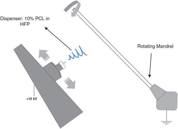
PCL was dissolved in HFP to create homogeneous 10% (w/v) solutions. All constructs were fabricated using an IME electrospinning machine (IME Technologies, Netherlands). The PCL solution was loaded into a 5 ml syringe that was connected to a 23-gauge dispenser needle via PTFE tubing. A high voltage of 15 kV was induced between the dispenser tip and a Teflon-coated stainless steel mandrel (ID = 1.1 mm). The solution was pushed through the dispenser tip and the resulting fibers were collected on the target. The solution flow rate was maintained at 0.05 ml/min using a syringe pump. The dispenser moved laterally at 300 mm/s and was positioned 12 cm away from the mandrel that was rotating at a speed of 300 rpm. Electrospinning was conducted inside a chamber with a climate control system to maintain a temperature of 25°C and humidity of 30%. The total dispensed volume of PCL solution was 0.4 ml for each graft.
A visual description of the electrospinning setup is provided in Figure 1.
FIGURE 1.
Electrospinning setup. A high voltage of 15 kV was applied to dispense a 10% PCL solution in HFP and generate a stream of PCL fibers that landed on a mandrel. The dispenser was laterally moving at a speed of 300 mm/s and the mandrel was rotating at 300 rpm
2.1.1 ∣. Thermobonding
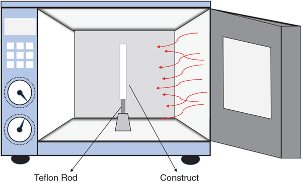
The electrospun constructs (N = 50) were separated into 10 groups including electrospun PCL (no thermobonding) as the control and 9 thermobonded groups as shown in Table 1. Each experimental group (n = 5) is defined by a specific thermal treatment condition, i.e., temperature and duration of treatment. Higher temperature and longer treatment duration are associated with a higher degree of thermobonding. To prevent collapse or shrinkage of the tubular constructs during thermobonding and also maintain a consistent inner diameter across all groups, each electrospun construct was mounted on a Teflon-coated stainless steel rod (OD = 1.1 mm) prior to thermal treatment. Thermobonding was conducted by placing the electrospun constructs in the center of a forced convection oven. Figure 2 illustrates the convective heat flux around the tubular constructs. After applying thermal treatment, the grafts were left untouched for 60 s at room temperature to ensure an adequate cool down and solidification of the structure before they were removed from the rod.
TABLE 1.
Experimental groups (each n = 5) at varying temperatures and treatment duration
| Time | |||
|---|---|---|---|
| Temperature | 54°C-15 s | 54°C-30s | 54°C-45 s |
| 57°C-15 s | 57°C-30s | 57°C-45 s | |
| 60°C-15 s | 60°C-30s | 60°C-45 s |
Note: Electrospun PCL constructs with no thermobonding was used as the control group.
FIGURE 2.
Thermal treatment: convective heat flux was applied to the constructs in order to thermally bond the electrospun fibers
2.2 ∣. Permeability testing and thickness Measurement
Electrospun PCL constructs are porous, allowing fluid to penetrate through their structure in response to intraluminal pressure. Darcy law governs the motion of slow-moving fluids in a porous medium.17
| (1) |
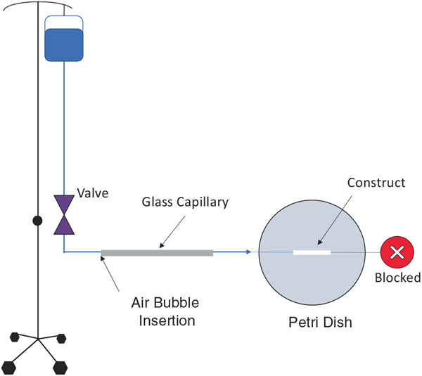
, is volumetric flow rate per unit area, is the apparent permeability and is the specific weight of the fluid. To measure the permeability, constructs were cut into 2-cm segments and cannulated between glass capillaries using sutures and cyanoacrylate glue. The sutures were wrapped at each end of the constructs several times to ensure no leakage through the ends upon exposure to pressure. The construct outlet was connected to a female cap by capillary glass and tubing to block fluid flow. The inlet was connected to a store of deionized water via a capillary glass (ID = 1.12mm) and tubing to apply hydrostatic pressure. The capillary glass was briefly disconnected from the tubing to insert an air bubble into the system. This bubble was exposed to a pressure of 100mmHg using a two-way stopcock. Pressure moved the bubble through the capillary glass as water exited the porous structure of the mounted PCL construct. The velocity of the air bubble was calculated using the measured displacement and time. Figure 3 illustrates the experimental setup used for permeability testing. The permeability was calculated using the following equation, which is derived from Equation (1).
| (2) |
where is the velocity of the air bubble, is the luminal area of the 1.12 mm-diameter glass capillary, is the construct thickness, is the pressure, is the inner diameter of the porous construct, and is the permeable length of the graft (between the sutures). The thickness of thermobonded constructs were measured using a caliper.
FIGURE 3.
Experimental setup for permeability testing. A hydrostatic pressure of 100 mmHg was applied to an air bubble and the velocity of the bubble was used to calculate the permeability
2.3 ∣. Uniaxial tensile testing
Following thermal treatment, constructs were cut into 1-cm segments for mechanical testing. These segments were then sliced longitudinally to yield rectangular strips with aspect ratios between 1:3 and 1:5. All dimensions of the strip were measured prior to testing. Each strip was manually positioned between the grips of a custom-made uniaxial tensile testing device.
The strips were stretched to 6% of their initial lengths (stretch ratio = 1.06) as larger stretch ratios caused plastic deformations. The samples underwent 15 load-unload cycles and the final cycle was used to generate Cauchy stress-stretch ratio curves. Cauchy stress was calculated using force measurements, initial cross-sectional area, and specimen stretch ratios. Tangential modulus values were calculated at the maximum stretch ratio (1.06).
2.4 ∣. Structural characterization
Construct morphology was assessed using scanning electron microscopy (SEM). 1-cm representative segments were cut from a random construct from each group and used for imaging and analysis. Segments were sputter coated (PdAu) to prepare for SEM imaging using an FEI Apreo microscope. A previously developed MATLAB-based image processing code was utilized to calculate the fiber diameter distribution.18,19
2.5 ∣. Suture retention strength and burst pressure testing
We used our uniaxial testing setup to determine the suture retention strength of the control constructs and those subjected to the highest degree of thermobonding (60°C-45 s). This test was conducted in accordance with ANSI/AAMI/ISO 7198 (cardiovascular implants: tubular vascular prostheses). The constructs (each n = 5) were cut into 1.5-cm segments and proximally clamped into the top grip of the uniaxial testing device. They were then sutured approximately 2 mm away from their distal ends using a single 6–0 monofilament prolene suture. The free ends of the suture were secured inside the bottom grip. Samples were then pulled at a rate of 2 mm/s until mechanical failure.20 The maximum force achieved prior to sample failure was used as the outcome for suture retention force. The burst pressures of thermobonded (60°C-45 s) and control PCL constructs were determined by increasing the intraluminal pressure until rupture occurred. To this end, the constructs were cannulated, sutured, and glued on both sides. One end of the construct was attached to an inflation device (Namic fluid management) and the other end was blocked off. Deionized water was infused and burst pressure was defined as the maximum pressure reached before rupture.
2.6 ∣. Degradation analysis
Electrospun PCL (control) and thermobonded constructs at 60°C-45 s were sliced into 1-cm segments for degradation testing. Phosphate buffer solutions of 0, 0.4, and 0.8 mg/ml lipase from Pseudomonas cepacia were prepared and shaken via vortex to ensure homogeneity. Each construct segment was weighed and then submerged in 1 ml of lipase solution inside a 15 ml conical tube. The submerged constructs were then placed onto a shaker plate inside an incubator at 37°C for 24 h. Immediately following incubation, the constructs were washed with deionized water and set inside separate petri dishes. The petri dishes were placed inside a convection oven to dry at 42°C for 24 h.21 The dried constructs were then weighed and returned to the incubator in conical tubes with refreshed lipase solution. The degradation was observed over the course of 4 days (excluding drying time) and percent remaining weight was calculated using the following formula:
| (3) |
Since crystallinity is one of the factors that can impact degradation rate, we performed XRD analysis on the thermobonded PCL constructs at 60°C-45 s and control electrospun constructs to evaluate any change in crystallinity in response to thermal treatment.
2.6.1 ∣. Statistical analyses
The normality of all data sets were assessed using the Kolmogorov–Smirnov test. We used one-way ANOVA and Kruskal–Wallis tests to infer statistical differences in permeability, tangential modulus, and thickness data sets depending on the normality status. We used unpaired t-tests to analyze suture retention strength and crystallinity data.
3 ∣. RESULTS
3.1 ∣. Permeability
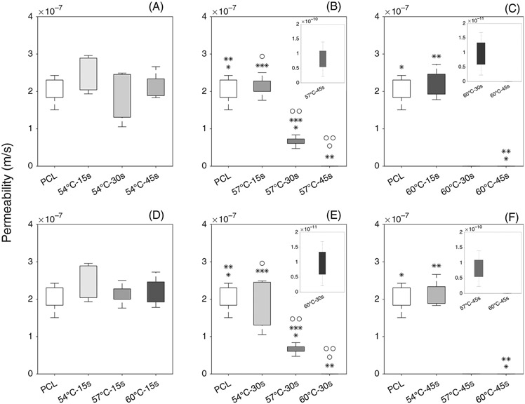
Figure 4 demonstrates the statistical differences between groups at different temperatures and treatment durations. Very low permeability values in the range of le−10 m/s to le−12 m/s were shown in a magnified plot to demonstrate the variability.
FIGURE 4.
Permeability of electrospun control PCL and thermobonded PCL constructs: (A–C) Effect of time is shown at 54°C (A), 57°C (B), and 60°C (C); (D–F) Effect of temperature is shown at 15 s (D), 30s (E), and 45 s (F)
3.1.1 ∣. Effect of time
Constructs treated at 54°C for different durations were not statistically different from the control group or each other. Thermal treatment for 57°C-15 s did not significantly affect the permeability as compared to the control group. Both 57°C-30s and 57°C-45 s groups had significantly lower permeabilities than the 57°C-15 s and control group. When thermobonding duration was increased from 30 to 45 s, we also observed a statistically significant reduction in permeability values. At 60°C, thermobonding occurred at a much higher rate and resulted in a (non-significant) reduction in permeability after only 30 s of treatment. Exposure of these constructs to 60°C for 45 s entirely fused the fibers, removed the interconnected pores, and reduced the permeability to zero. The permeability of 60°C-45 s constructs were significantly lower than the control group as well as the 60°C-15 s group.
3.1.2 ∣. Effect of temperature
Upon 15 s of exposure to convective heat, permeability values were not significantly altered in the temperature range of 54–60°C. The permeability of electrospun PCL controls were not statistically different from the grafts that underwent thermobonding at 54°C for 30 s. Also, among constructs that were treated for 30 s, we found statistical differences between both control and 54°C group and those thermobonded at 57°C and 60°C. Under this treatment time, increasing the temperature from 57 to 60°C significantly reduced the permeability values. Lastly, 60°C-45 s constructs were significantly less permeable than the control and 54°C-45 s group.
3.1.3 ∣. Permeability at 57°C
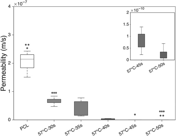
The pace of thermobonding at 57°C allowed a finer control and modulation of permeability. Therefore, multiple additional time points ranging from 30 to 50 s with 5 s intervals were considered for further permeability testing. Figure 5 represents the permeability values of constructs under 57°C at multiple time points. A decreasing trend in permeability values was observed as we increased the duration of treatment. Statistical differences were found between the control and both the 57°C-45 s and 57°C-50s groups. Also, the 57°C-30s group demonstrated a significantly higher permeability than 57°C-50s group.
FIGURE 5.
Permeability of electrospun thermobonded PCL constructs at 57°C and various time points (n = 5 each)
3.2 ∣. Thickness
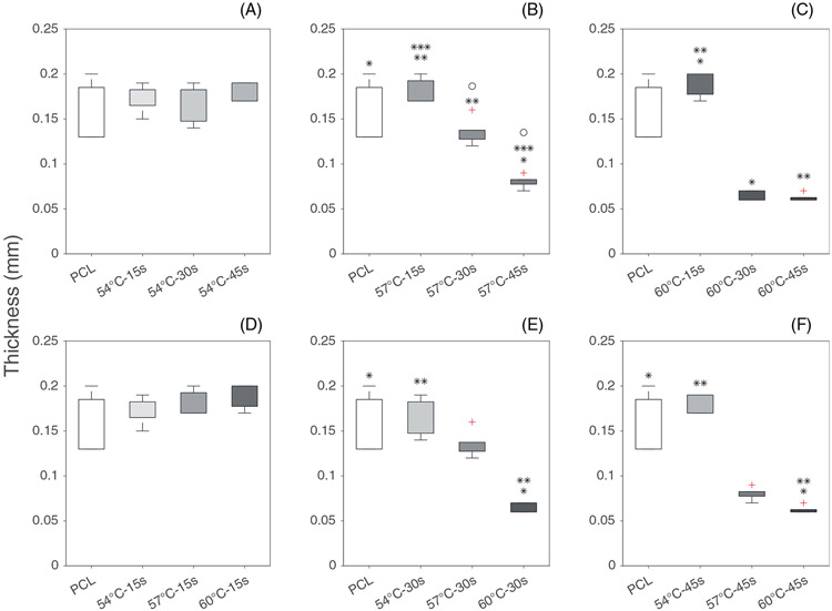
The effect of thermobonding on the thickness of the constructs is demonstrated in Figure 6. Reduction in constructs' thickness due to thermobonding followed similar trends observed in permeability data. The higher degrees of thermobonding (higher temperature and longer exposure time) diminished the thickness of the electrospun constructs as the fibers fused into each other and reduced the voids. The median thickness of electrospun control PCL and 60°C-45 constructs were 150 μm (IQR = 55 μm) and 60 μm (IQR = 2.5 μm), respectively. The thickness values of constructs following thermobonding did not fall below 60 μm at any combination of temperature and thermal treatment duration.
FIGURE 6.
Thickness of electrospun control PCL and thermobonded PCL constructs: (A–C) Effect of time is shown at 54°C (A), 57°C (B), and 60°C (C); (D–F) Effect of temperature is shown in 15 s (D), 30s (E), and 45 s (F)
3.3 ∣. Uniaxial tensile testing
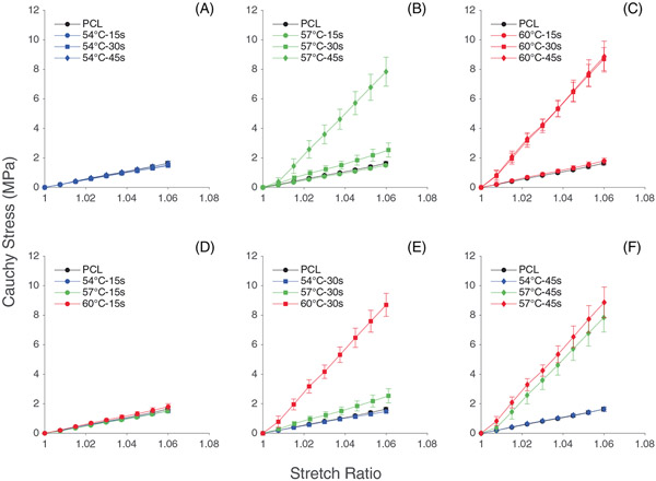
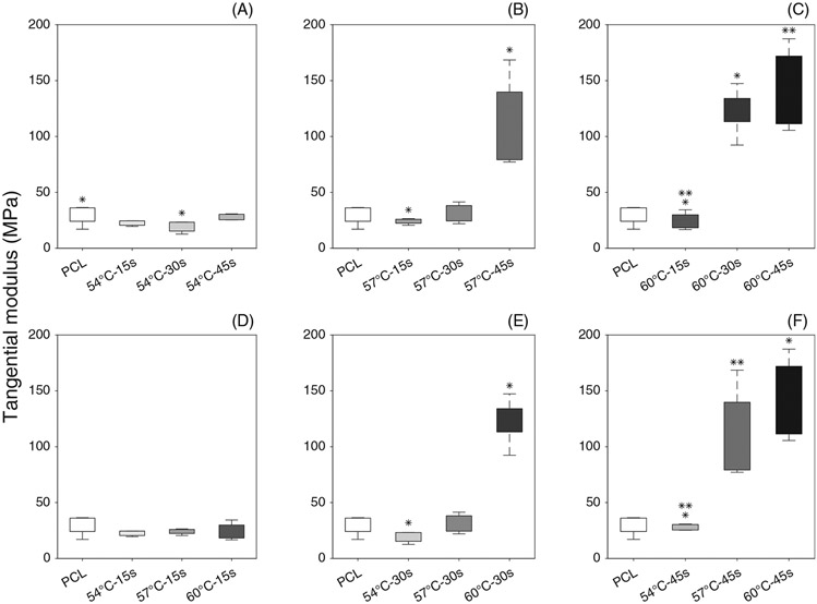
Figure 7 shows the Cauchy stress-stretch plots of thermobonded PCL constructs under uniaxial tension. The mechanical responses of all samples that underwent treatment at 54°C and all samples exposed to heat for 15 s were similar to that of the control group. Increasing thermobonding duration to 30 and 45 s at 57°C and 60°C stiffened the PCL strips. Accordingly, tangential modulus values of these constructs were calculated at the maximum stretch ratio (1.06). Figure 8 shows the statistical differences between groups for tangential modulus.
FIGURE 7.
Cauchy stress vs. stretch of electrospun (control) and thermobonded PCL constructs: (A–C) Effect of time is shown at 54°C (A), 57°C (B), and 60°C (C); (D–F) Effect of temperature is shown at 15 s (D), 30s (E), and 45 s (F)
FIGURE 8.
Tangential modulus of electrospun (control) and thermobonded PCL constructs: (A–C) Effect of time is shown at A (54°C), B (57°C), and C (60°C); (D–F) Effect of temperature is shown at D(15 s), E(30s) and F(45 s)
3.3.1 ∣. Effect of time
We found a statistical difference in tangential modulus values between the control and 54°C-30s groups. At both 57°C and 60°C, the 15 s groups had significantly lower tangential modulus values as compared to 45 s groups. Also, the constructs that were thermally treated at 60°C for 30s had significantly higher tangential modulus than those treated at the same temperature but only for 15 s.
3.3.2 ∣. Effect of temperature
The tangential modulus values of thermobonded constructs under 54°C-30s condition were significantly lower than that of the 60°C-30s group. The constructs treated at 60°C or 57°C for 45 s were significantly stiffer than those in the 54°C-30s group.
3.4 ∣. Suture retention strength and burst pressure
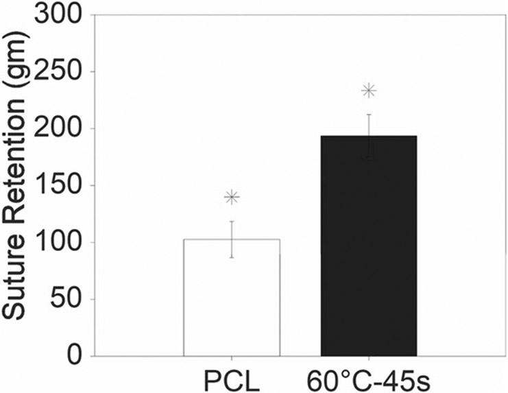
Figure 9 demonstrates the suture retention strength of electrospun control PCL and thermobonded PCL constructs under 60°C-45 s condition. Our data revealed significantly higher suture retention values for 60°C-45 s constructs as compared to the control. In the 60°C-45 s thermobonded constructs, we observed circumferential tearing in addition to the axial tearing during the test whereas the PCL control constructs were solely torn in the axial direction. The mean burst pressure of the thermobonded constructs (60°C-45 s) was 1.42 ± 0.16 MPa (10,650 ± 1200 mmHg). PCL control constructs did not rupture due to high permeability and loss of pressure.
FIGURE 9.
Suture retention of electrospun control PCL and thermobonded PCL constructs at 60°C-45 s
3.5 ∣. Structural characterization
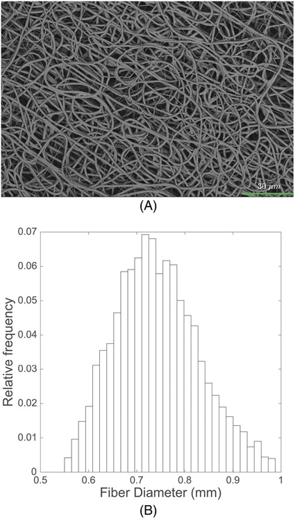
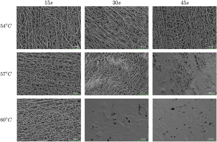
Figure 10 represents the SEM images of the electrospun control PCL construct and the corresponding fiber diameter distribution, which shows a median fiber diameter of approximately 0.74 μm (IQR = 0.12). Figure 11 shows SEM images of the thermobonded PCL constructs at each combination of temperature and treatment duration. The fibers of the constructs treated at 54°C and those treated for 15 s were unaffected. A higher degree of thermobonding and fiber fusion was observed at higher temperatures and treatment durations. Constructs exposed to 57°C for 45 s and 60°C for 30 and 45 s contained very few well-defined fibers.
FIGURE 10.
Electrospun PCL control group: (A) SEM image of electrospun PCL fibers and (B) Fiber diameter distribution
FIGURE 11.
SEM images from the luminal surfaces of thermobonded PCL constructs at different temperatures and thermal treatment duration
3.6 ∣. Degradation Analysis
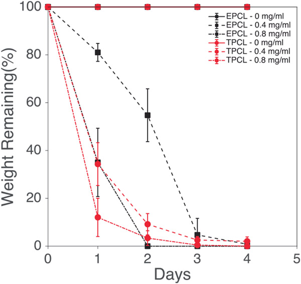
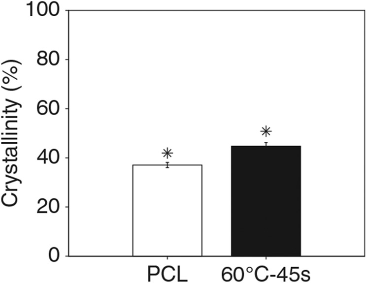
Figure 12 shows the degradation of electrospun and thermobonded PCL constructs treated at 60°C-45 s for various concentrations of lipase. Neither the electrospun PCL (control) nor the 60°C-45 s constructs were degraded after 4 days of exposure to PBS. Increasing lipase concentration to 0.4 mg/ml significantly reduced the remaining weight of both constructs, but electrospun PCL degraded slower than 60°C-45 s constructs for the first 3 days. On day 4, approximately 1% and 3% of the initial weights were remaining in the electrospun and thermobonded PCL constructs, respectively, indicating the faster degradation of electrospun PCL. Further increasing the lipase concentration to 0.8 mg/ml accelerated the degradation process for both groups. At this concentration, the thermobonded PCL degradation rate was still faster than control constructs on the first day; however, the degradation rate of electrospun PCL surpassed the 60°C-45 s constructs after day 1. All the constructs exposed to 0.8 mg/ml lipase were fully degraded after 4 days. Figure 13 demonstrates the degree of crystallinity in the 60°C-45 s group as compared to electrospun control PCL. The mean degree of crystallinity of electrospun control PCL was 37.06% whereas thermobonded PCL under 60°C-45 s condition had a significantly higher mean crystallinity of 44.76%.
FIGURE 12.
Degradation of electrospun and thermobonded PCL constructs in different lipase concentrations
FIGURE 13.
Crystallinity of electrospun and thermobonded PCL constructs at 60°C-45 s
4 ∣. DISCUSSION
In this study, we investigated the effects of convective thermal treatment on the transport properties, mechanical response, and structure of electrospun PCL constructs. Increasing the temperature and exposure time promoted the effects of thermal treatment. Thermobonding was ineffective at 54°C regardless of the duration of treatment as the properties and structure were not altered from their original state. As we increased the temperature and time of treatment, we observed orders of magnitude reduction in permeability which trended toward zero (60°C-45 s), indicative of total fiber fusion. Thermobonding at 57°C allowed the greatest tunability of hydraulic permeability via treatment duration. The thicknesses of thermobonded constructs were significantly reduced at higher temperatures and longer treatment durations. Mechanical testing of thermally-treated PCL constructs showed substantial enhancement in mechanical strength, increasing both tangential modulus and suture retention values. Our findings also indicated a higher degradation rate of thermobonded constructs (60°C-45 s) as compared to electrospun control PCL.
The permeability of native vascular tissue is much lower than electrospun grafts. This lower permeability is caused by an endothelial monolayer that dynamically controls permeability for the passage of nutrients, oxygen, and other essential molecules.22,23 In this work the permeability of thermobonded constructs was reduced from an order of le−7 m/s (electrospun PCL) to le−11 m/s (57°C-45 s) and 1e−12 m/s (60°C-30s). These permeability values are close to the permeability of rat aortic tissue (in the order of 1e−12 m/s).24
Other studies have confirmed the mechanical strengthening effects of heat treatment on polymers, including PCL, which is consistent with our findings.7,9,15,16,25 Although thermobonded constructs under 60°C-30s, 60°C-45 s, and 57°C-45 s conditions demonstrated a tangential modulus close to saphenous vein elastic modulus (~130 MPa) in the axial direction.26 Many other studies have found morphological changes and fiber fusion due to the thermal treatment which are consistent with our findings.7,9,15,16,25
The most important factors that can affect the degradation rate of scaffolds are surface area, crystallinity as well as the removal of acidic breakdown products. Our XRD data provide evidence that thermal treatment of PCL constructs has altered the crystalline structure of the polymer. Greater crystallinity of polymers is typically associated with slower degradation27,28 which did not occur in our experiments. Thermobonded PCL constructs have less exposed surface area for degradation which is expected to slow down the degradation process. Despite higher crystallinity and less surface area, we observed a faster degradation in the thermobonded PCL constructs (60°C-45 s). We speculate that the increased porosity of control electrospun constructs allowed for easier removal of degradation acidic byproducts while the lower porosity of thermobonded constructs may have limited the removal of these breakdown products, thus leading to an increased degradation rate of the polymer. Consistently, a lower degradation of PLGA high-porosity scaffolds compared to 0% porosity scaffolds has been demonstrated in another study.29 This result has been attributed to the contribution of the greater surface area of high porosity scaffolds to easier removal of acidic breakdown products which can diminish the chance of autocatalysis. In a PCL degradation study, researchers have also shown that solvent cast films of PCL degraded completely in 4 days under enzymatic degradation in a PS lipase concentration of 0.50 mg/ml30 which corroborates our results for total degradation of constructs after 4 days using a lipase concentration of 0.40 mg/ml.
While we successfully fabricated and characterized thermobonded PCL constructs, this work had several limitations. First, the SEM images of thermobonded constructs showed a non-uniform structural change in response to heat. This non-uniform changes and data variation partly stem from the temperature non-uniformity (±1°C) inside the oven which is dependent on the design of the oven's chamber and airflow. Our oven's convective air flows from a limited number of holes that are located on specific spots on one side of the oven's interior wall. Therefore, the exact location of the samples in 3D space, including distance from the convection wall and location with respect to the convection holes, can substantially impact the exposure of the samples to convective heat flow. We believe that a customized oven with a more controlled and optimized thermal transport would result in less variation. Secondly, environmental conditions such as room temperature and air intake of the oven could potentially have a major impact on the thermal bonding process given the short and rapid nature of convective heat treatment. Lastly, due to the nonideal electrospinning conditions, there were variations in the thickness of the constructs which could affect the heat transport in the thermobonding process. Further investigation is required to confirm the effect of thickness on heat transport through and between the electrospun fibers.
5 ∣. CONCLUSION
Thermobonding of electrospun PCL fibers can be utilized to modulate the transport properties of vascular engineered constructs. Moreover, it improves the mechanical strength and suture retention strength of the scaffolds. Future in-vivo studies are required to reveal the effect of thermobonding on graft dilation and blood leakage prevention.
ACKNOWLEDGMENTS
This research was funded by the American Heart Association award 20PRE35211036 to AB and NIH award R01HL157017 to JPVG and WRW.
Footnotes
CONFLICT OF INTEREST
The authors declare no conflict of interest.
DATA AVAILABILITY STATEMENT
The data that support the findings of this study are available from the corresponding author upon reasonable request.
REFERENCES
- 1.Yalcin Enis I, Gok Sadikoglu T. Design parameters for electrospun biodegradable vascular grafts. J Ind Text. 2018;47:2205–2227. [Google Scholar]
- 2.Haruguchi H, Teraoka S. Intimal hyperplasia and hemodynamic factors in arterial bypass and arteriovenous grafts: a review. J Artif Organs. 2003;6:227–235. [DOI] [PubMed] [Google Scholar]
- 3.Ballyk P, Walsh C, Butany J, Ojha M. Compliance mismatch may promote graft—artery intimal hyperplasia by altering suture-line stresses. J Biomech. 1998;31:9. [DOI] [PubMed] [Google Scholar]
- 4.Weber M, Steinle H, Golombek S, et al. Blood-contacting biomaterials: In vitro evaluation of the hemocompatibility. Front Bioeng Biotechnol. 2018;6:99. [DOI] [PMC free article] [PubMed] [Google Scholar]
- 5.Ruggeri ZM. Platelet adhesion under flow. Microcirculation. 2009;16:58–83. [DOI] [PMC free article] [PubMed] [Google Scholar]
- 6.Matsuzaki Y, Iwaki R, Reinhardt JW, et al. The effect of pore diameter on neo-tissue formation in electrospun biodegradable tissue-engineered arterial grafts in a large animal model. Acta Biomater. 2020;115:176–184. [DOI] [PubMed] [Google Scholar]
- 7.de Valence S, Tille JC, Giliberto JP, et al. Advantages of bilayered vascular grafts for surgical applicability and tissue regeneration. Acta Biomater. 2012;8:3914–3920. [DOI] [PubMed] [Google Scholar]
- 8.You Y, Won Lee S, Jin Lee S, Park WH. Thermal interfiber bonding of electrospun poly(l-lactic acid) nanofibers. Mater Lett. 2006;60:1331–1333. [Google Scholar]
- 9.Lee SJ, Oh SH, Liu J, Soker S, Atala A, Yoo JJ. The use of thermal treatments to enhance the mechanical properties of electrospun poly (ϵ-caprolactone) scaffolds. Biomaterials. 2008;29:1422–1430. [DOI] [PubMed] [Google Scholar]
- 10.Nezarati RM, Eifert MB, Dempsey DK, Cosgriff-Hernandez E. Electrospun vascular grafts with improved compliance matching to native vessels. J Biomed Mater Res Part B, Appl Biomater. 2015;103:313–323. [DOI] [PMC free article] [PubMed] [Google Scholar]
- 11.Ramanujam R, Sundaram B, Janarthanan G, Devendran E, Venkadasalam M, Milton MJ. Biodegradable polycaprolactone nano-particles based drug delivery systems: a short review. Biosci Biotechnol Res Asia. 2018;15:679–685. [Google Scholar]
- 12.Miller K, Hsu J, Soslowsky L. 6.618 - materials in tendon and ligament repair. In: Ducheyne P, ed. Comprehensive Biomaterials. Elsevier; 2011:257–279. [Google Scholar]
- 13.Manoukian OS, Sardashti N, Stedman T, et al. Biomaterials for tissue engineering and regenerative medicine. In: Narayan R, ed. Encyclopedia of Biomedical Engineering. Elsevier; 2019:462–482. [Google Scholar]
- 14.Endres H-J, Siebert-Raths A 10.19—Performance profile of biopolymers compared to conventional plastics. In: Matyjaszewski K, Möller M, eds. Polymer Science: A Comprehensive Reference. Elsevier; 2012:317–353. [Google Scholar]
- 15.Kancheva M, Toncheva A, Manolova N, Rashkov I. Enhancing the mechanical properties of electrospun polyester mats by heat treatment, express. Polym Lett. 2015;9:49–65. [Google Scholar]
- 16.Borisova I, Stoilova O, Manolova N, Rashkov I. Modulating the mechanical properties of electrospun phb/pcl materials by using different types of collectors and heat sealing. Polymers. 2020;12:693. [DOI] [PMC free article] [PubMed] [Google Scholar]
- 17.Keyes JT, Lockwood DR, Simon BR, Vande Geest JP. Deformationally dependent fluid transport properties of porcine coronary arteries based on location in the coronary vasculature. J Mech Behav Biomed Mater. 2013;17:296–306. [DOI] [PMC free article] [PubMed] [Google Scholar]
- 18.Ezeakacha CP, Rabbani A, Salehi S, Ghalambor A. Integrated image processing and computational techniques to characterize formation damage. SPE International Conference and Exhibition on Formation Damage Control (D012S007R004); 2018. [Google Scholar]
- 19.Rabbani A, Salehi S. Dynamic modeling of the formation damage and mud cake deposition using filtration theories coupled with sem image processing. J Nat Gas Sci Eng. 2017;42:157–168. [Google Scholar]
- 20.L'Heureux N, Dusserre N, Konig G, et al. Human tissue-engineered blood vessels for adult arterial revascularization. Nat Med. 2006;12: 361–365. [DOI] [PMC free article] [PubMed] [Google Scholar]
- 21.Ardila DC, Liou JJ, Maestas D, et al. Surface modification of electrospun scaffolds for endothelialization of tissue-engineered vascular grafts using human cord blood-derived endothelial cells. J Clin Med. 2019;8: 1–21. [DOI] [PMC free article] [PubMed] [Google Scholar]
- 22.Claesson-Welsh L, Dejana E, McDonald DM. Permeability of the endothelial barrier: identifying and reconciling controversies. Trends Mol Med. 2021;27:314–331. [DOI] [PMC free article] [PubMed] [Google Scholar]
- 23.Gavard J. Endothelial permeability and ve-cadherin. Cell Adh Migr. 2014;8:158–164. [DOI] [PMC free article] [PubMed] [Google Scholar]
- 24.Chooi KY, Comerford A, Sherwin SJ, Weinberg PD. Intimal and medial contributions to the hydraulic resistance of the arterial wall at different pressures: a combined computational and experimental study. J Royal Soc Interface. 2016;13:20160234. [DOI] [PMC free article] [PubMed] [Google Scholar]
- 25.Abdal-Hay A, Bartnikowski M, Hamlet S, Ivanovski S. Electrospun biphasic tubular scaffold with enhanced mechanical properties for vascular tissue engineering. Mater Sci Eng C. 2018;82:10–18. [DOI] [PubMed] [Google Scholar]
- 26.Hasan A, Memic A, Annabi N, et al. Electrospun scaffolds for tissue engineering of vascular grafts. Acta Biomater. 2014;10:11–25. [DOI] [PMC free article] [PubMed] [Google Scholar]
- 27.Pantani R, Sorrentino A. Influence of crystallinity on the biodegradation rate of injection-moulded poly(lactic acid) samples in controlled composting conditions. Polym Degrad Stab. 2013;98:1089–1096. [Google Scholar]
- 28.Jenkins MJ, Harrison KL. The effect of crystalline morphology on the degradation of polycaprolactone in a solution of phosphate buffer and lipase. Polym Adv Technol. 2008;19:1901–1906. [Google Scholar]
- 29.Athanasiou K, Schmitz J, Agrawal C. The effects of porosity on in vitro degradation of polylactic acid-polyglycolic acid implants used in repair of articular cartilage. Tissue Eng. 1998;4:53–63. [Google Scholar]
- 30.Gan Z, Yu D, Zhong Z, Liang Q, Jing X. Enzymatic degradation of poly (ϵ-caprolactone)/poly(dl-lactide) blends in phosphate buffer solution. Polymer. 1999;40:2859–2862. [Google Scholar]
Associated Data
This section collects any data citations, data availability statements, or supplementary materials included in this article.
Data Availability Statement
The data that support the findings of this study are available from the corresponding author upon reasonable request.


