Abstract
Magnetic resonance imaging (MRI) is one of the most prevailing technologies to enable noninvasive and radiation-free soft tissue imaging. Operating a robotic device under MRI guidance is an active research area that has the potential to provide efficient and precise surgical therapies. MR-conditional actuators that can safely drive these robotic devices without causing safety hazards or adversely affecting the image quality are crucial for the development of MR-guided robotic devices. This paper aims to summarize recent advances in actuation methods for MR-guided robots and each MR-conditional actuator was reviewed based on its working principles, construction materials, the noteworthy features, and corresponding robotic application systems, if any. Primary characteristics, such as torque, force, accuracy, and signal-to-noise ratio (SNR) variation due to the variance of the actuator, are also covered. This paper concludes with a perspective on the current development and future of MR-conditional actuators.
Keywords: Magnetic resonance imaging (MRI), MR-conditional, Motor, Actuation, Pneumatic, Piezoelectric, Hydraulic
INTRODUCTION
Performing surgical procedures with a robotic system could potentially benefit both patients and surgeons.65,79,80 In the field of robot-assisted interventions, magnetic resonance imaging is one of the technologies that provides radiation-free scans for acquiring high-resolution images of the internal organs and bones. Unlike X-ray imaging and computed tomography (CT), MRI does not expose patients or operators to ionizing radiation, which is particularly important for those who are physically weak. Instead, MRI scanners image the water molecules in the body with a strong magnetic field. MRI is also superior to other imaging modalities when imaging soft tissues because of its imaging principles. These advantages have allowed MRI to become widely accepted in the clinical environment for diagnosis, and also for surgical guidance since it can be used to assist positional alignment of surgical instruments within the region of interest.9 It was reported in a clinical review for 200 patients that MRI provided valuable and high-quality information for intraoperative surgical strategy.59
Because of the strong magnetic field generated in the scanner bore, using of ferromagnetic materials is strongly prohibited inside the MRI room within the 5 gauss line due to safety issues and strong pull force exerted to the part except for situation in which the ferromagnetic material is used as a component of a MR-powered motor described in section “MR-Powered Motor”. In addition to ferromagnetic material, some non-ferromagnetic materials also produce interference and artifacts during the imaging process and thus are not allowed to be used in the MRI environment or their use should be limited. Robots intended for use in MR environments must meet the criteria to be rated either “MR conditional” or “MR safe,” as defined by the American Society for Testing and Materials (ASTM) and recognized by the FDA.87 MR conditional rating requires that items have been demonstrated to be safe in a specified MRI environment under defined conditions. MR safe rating requires that items pose no known hazard in any MRI environment.3 Given the safety and image quality requirements, novel, MR-conditional actuation methods must be considered for medical robots as an alternative to traditional electric motors.12,13
A very first MRI-conditional robotics application, a needle insertion manipulator, was designed and reported by Masamune in 1995, showing great potential for accurate controls and teleoperations in MRI-guided interventions.54 In recent years, huge progress has been made on building a MR-conditional, accurate and reliable surgical robots with a variety of actuation methods. MR-conditional actuation technologies include hydraulic or pneumatic principles, shape memory alloys, contractile polymers, piezoelectric actuation, and Bowden cables.45,86,99 Numerous prototypes of MR-conditional robots have been built, and documentation has been published regarding their configurations, validations and limitations. This paper reviews working principles, structure descriptions, actuation methods, and various experimental performance of these various prototypes. Although the characteristics of MR-conditional actuations have been briefly summarized in recent research and review papers,9 a comprehensive review focusing on the actuation methods for applications in MR environments is still lacking. The most recent comprehensive MR-conditional actuation review paper was published in 2006.31 In this paper, we aim to bridge the gap and provide an updated review of MR-conditional actuation, especially for those developed after 2006. This rest of this paper is arranged as follows: the searching engines and review methods are presented in “Methods of Review” section. “Review of MR-Conditional Actuations” describes the MR-conditional actuator working principle and the key features, and those motors are divided into four main categories, namely pneumatic, piezoelectric, hydraulic, and others. The summary and future challenges are covered in “Discussion and Future Work” section.
METHODS OF REVIEW
This research was conducted through the leading scientific research search engines and technical journals, including Google Scholar, IEEE Xplore, ASME, the Annals of Biomedical Engineering, the proceedings of the Hamlyn Symposium on Medical Robotics, the International Conference on Medical Image Computing and Computer-Assisted Intervention, and others. Initially, a general search by title was conducted in these online databases using keywords “all in title: MR conditional actuation OR MR compatible actuation OR MR safe actuation OR motor OR robot” to find relevant publications. The definition of MR conditional and MR safe can be found in the ASTM F2503–13 standards. The initial process yielded 86 publications from year 2006 to year 2019. A manual scan of each publication distilled that number to 34. From there, references cited in each of the 34 publications were studied, and relevant articles were added to expand the final list beyond the initial title search constraints. In addition, several actuation methods which have not been tested in MRI scanner but have the potential to be MR-conditional are also reviewed in this paper.
The review of the actuation methods is classified based on the working principles as presented in Fig. 1. Four main categories were selected: pneumatic motors, piezoelectric motors, hydraulic motors, and others, followed by several subclasses. From the author’s perspective, although pneumatic motors are various and diverse in their designs, they can be categorized into three types based on the principle of their actuator mechanisms: gear-based, deformation-based, and turbine-based. Piezoelectric motors, however, differ from pneumatic motors in that they are mostly commercially available. Therefore, the piezoelectric actuators are categorized based on commercial brands. These include the USR series (Shinsei Corporation, Tokyo, Japan), HR series (Nanomotion Ltd., Yokneam, Israel), PiezoMotor (PiezoMotor Uppsala AB, Uppsala, Sweden), and Inchworm (EXFO Electro-Optical Engineering Inc., Quebec City, Canada). Hydraulic actuations are not categorized because of the limited number of relevant publications. Finally, other actuators reviewed include shape-memory actuators (SMA), MR-powered actuators, and elastic actuators.
FIGURE 1.
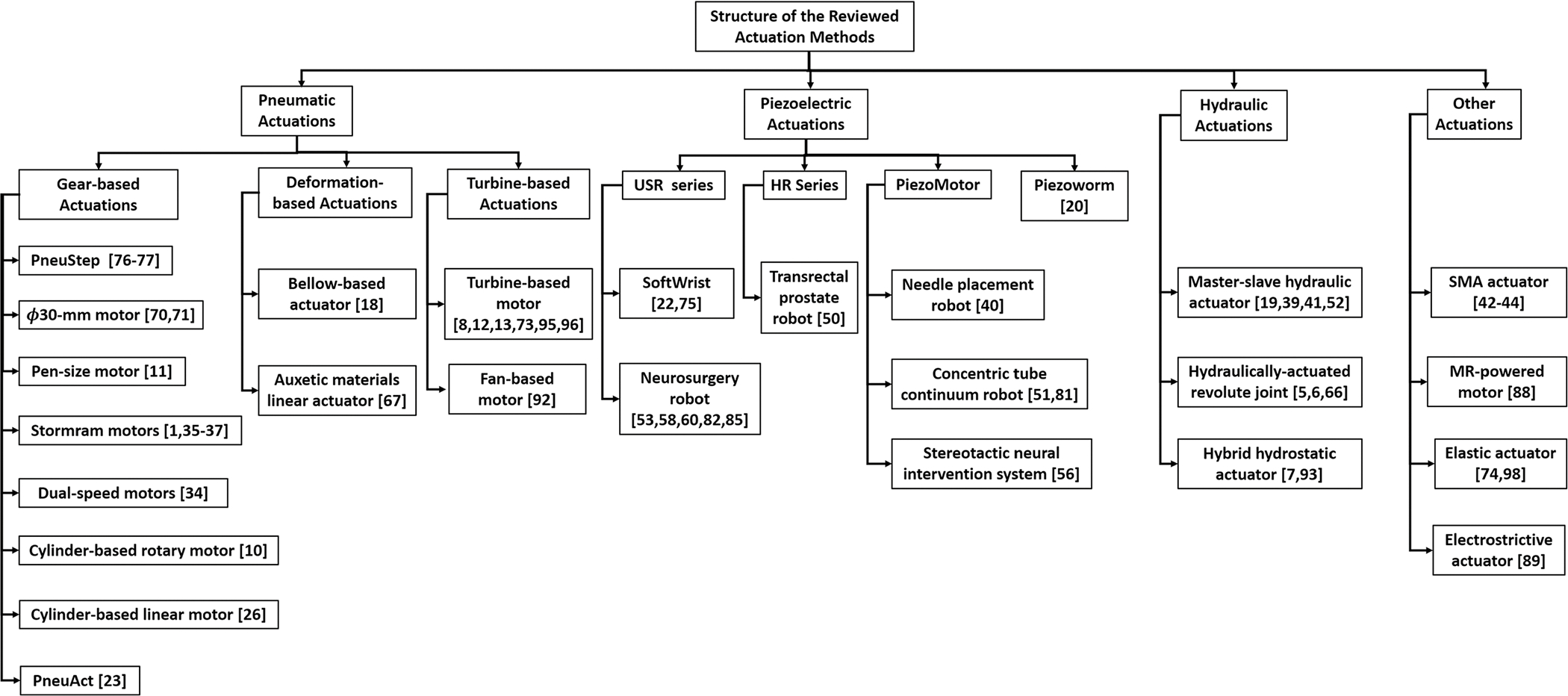
MR-conditional actuation methods.
REVIEW OF MR-CONDITIONAL ACTUATIONS
The actuation methods presented are classified into four types based on the working principle: pneumatic, piezoelectric, hydraulic, and other. The characteristics of each actuation method are summarized in Table 1 and explored in further detail. Note that the information in the Features column was faithfully extracted from the corresponding reference papers.
TABLE 1.
Comparative study of the MR conditional actuation method.
| Actuation Type | Projects | Features | References | |
|---|---|---|---|---|
|
| ||||
| Pneumatic | PneuStep | (a) Torque: 600 N mm at low speed, 150 N mm at
high speed (b) Not backdrivable (c) Accuracy of 0.5 mm (d) No SNR reduction in 7T environment |
76–78 | |
| Sajima motor | (a) Torque: 140 N mm at low speed, 5 N mm at
high speed (b) Not backdrivable (c) Accuracy of 0.43 ± 0.15 mm (d) No SNR reduction observed (e) Simple structures |
70,71 | ||
| Pen-size motor | (a) Torque: 2.5 N mm at lo w speed, 1.25 N mm
at high speed (b) Not backdrivable (c) Accuracy not mentioned (d) SNR reduction of 2.49% (e) Compact design (10 mm) |
11 | ||
| Stormram motors | (a) Force: maximum 63 N for latest
version (b) Not backdrivable (c) Accuracy of 0.7 mm for latest version (d) No SNR reduction observed |
1,35–37 | ||
| Dual-speed motors | (a) Force: maximum 24 N, torque: 74 N
mm (b) Not backdrivable (c) Accuracy of 0.09 mm (d) SNR test not reported (e) Fast targeting (10 times faster than PneuStep, Stormram linear motor) |
34 | ||
| Cylinder-based rotary motor | (a) Torque: maximum 800 N mm at low speed, 500
N mm at high speed (b) Backdrivable (c) Accuracy of 2° (d) SNR reduction of 2.35% |
10 | ||
| Cylinder-based linear motor | (a) Force: maximum 47 N (b) Backdrivable (c) Accuracy of 0.26 mm (d) SNR reduction 4.2% in T2W TSE (e) RAPID response time (4 ms) |
26 | ||
| PneuAct | (a) Torque: 140 N mm at low speed, 10 N mm at
high speed (b) Backdrivable (c) Small stepper resolution (1.5°) () No SNR reduction observed |
23 | ||
| Bellow-based actuator | (a) Force: maximum 33 N (b) Not backdrivable (c) Accuracy of 0.013 mm and 0.018° (d) No SNR reduction observed in 3T scanner |
18 | ||
| Auxetic materials linear actuator | (a) Force: tested on 2 N load (b) Not backdrivability (c) Accuracy not reported (d) No SNR reduction observed in 1.5T scanner |
67 | ||
| Turbine-based motor | (a)Torque: maximum 919 N mm (b) Backdrivable (c) Accuracy of 2.19 mm (d) Max SNR reduction of 5% in 3T scanner |
8,12,13,73,95,96 | ||
| Fan-based motor | (a) Torque: 28 N mm at low pressure, 3 N mm at
high pressure (b) Backdrivable (c) Accuracy not reported (d) SNR test not reported |
92 | ||
| Piezoelectric | USR series | MR-SoftWrist | (a) Force: maximum 8 N, torque: maximum 630 N
mm (b) Not backdrivable (c) Accuracy of 2.25° (d) SNR reduction of 6% in 3T scanner |
22,75 |
| Neurosurgery robot | (a) Force or torque not reported (b) Not backdrivable (c) Accuracy of 1.37 mm (d) 10.3% SNR reduction in T1 scanner |
53,58,60,82,85 | ||
| HR series | Transrectal prostate robot | (a) Force: stall force of 24 N, torque:
maximum 1080 N mm (b) Not backdrivable (c) Average accuracy of 2.4 mm (d) SNR reduction of 5% with novel ceramic motor driver |
50 | |
| PiezoMotor | Needle placement robot | (a) Force not reported (b) Not backdrivable (c) Accuracy not reported (d) No SNR reduction observed in 3T scanner |
40 | |
| Concentric tube robot | (a) Concentric tube manipulation (b) Not backdrivable (c) Maximum error of 2.24 mm (d) SNR reduction of less than 2% |
51,81 | ||
| Stereotactic neural intervention system | (a) FORCE not reported (b) Not backdrivable (c) Accuracy not reported (d) No noticeable artifact in T1 and T2 scanner |
56 | ||
| Piezoworm | Piezoworm | (a) Torque: theoretical 5 N mm (b) Not backdrivable (c) Accuracy not reported (d) SNR reduction not reported |
20 | |
| Hydraulic | Master-slave hydraulic actuator | (a) Torque: 1470 N mm (b) Not backdrivable (c) Accuracy of 4.5 mm (d) SNR loss less than 2% (e) Dynamic lag of 66 ms for 10 m hydraulic transmission |
19,39,41,52 | |
| Hydraulically-actuated joint | (a) Force: 18.4 N (b) Not backdrivable (c) Accuracy not reported (d) SNR reduction not reported |
5,6,66 | ||
| Hybrid hydrostatic actuator | (a) Torque: delivered 2700 N mm (b) Backdrivable, but has passively-safe system (c) Accuracy not reported (d) SNR reduction not reported |
7,93 | ||
| Others | Shape-memory alloy actuator | (a) Force: maximum 1.5 N (b) Not backdrivable (c) Accuracy not reported (d) SNR reduction of 10% |
42–44 | |
| MR-powered motor | (a) Force: maximum 0.76 N (b) Not backdrivable (c) Accuracy not reported (d) No SNR reduction observed (e) Wireless powered |
88 | ||
| Elastic actuator | (a) torque: maximum 2000 N mm (b) Backdrivable (c) Accuracy not reported (d) SNR reduction not reported, but compatible to MRI |
74,98 | ||
| Electrostrictive actuator | (a) Force or torque: not reported (b) Backdrivability not available (c) Accuracy not reported (d) SNR reduction not reported, but imaging shows compatibility to MRI (e) Reconfigurable surface-imaging coil |
89 | ||
Pneumatic Motors
Pneumatic actuators rely on the compressed air supply to create the dynamic torque or speed output. With the advancements of additive manufacturing techniques, pneumatic actuators can be fabricated with MR-safe materials, such as ABS or resin that can be electromagnetically decoupled from the MR scanner.
Pneumatic pistons and motors are the two main types of MR-conditional pneumatic actuation methods.27,76 Pneumatic pistons, fabricated using graphite and glass, can provide linear translational motion but require an additional transmission mechanism to achieve rotational motion and a pneumatic circuit that can generate cyclic and sequential piston motion. Pneumatic actuators can be fabricated with MR-conditional plastic materials (e.g., nylon and polyamide) through additive manufacturing. The first MR-conditional pneumatic actuator was proposed by Dan Stoianovici in 2007 and has been applied in various MR-conditional robotic designs.76,77 Following his pioneering work, several MR conditional actuators have been proposed in the past ten years due to the easy manufacturability.4,10–12,18,26,36,38,70–72 Major limitations of pneumatic actuation include difficulty to control due to nonlinear air compressibility.
Gear-Based Actuation
PneuStep
The PneuStep, invented by Stoianovici et al., comes from the idea that “end-to-end motion of a piston within its cylinder is always exact.”76 As Fig. 2a shows, the PneuStep is driven by three diaphragm cylinders with grounded bases, which are pressurized through their ports. The diaphragm cylinders are attached to the outer gear, which is supported with three connecting rods by equal-crank, parallelogram mechanisms. The cranks are placed around the same central axis and equally spaced between the diaphragm cylinders. The outer gear engages a central spur gear at a constant eccentricity such that the two gears always satisfy the rolling condition. The pneumatic distributor, which control the air supply to cylinders, and optical encoder are precisely designed for control purposes. Note the fiber optical encoder was used to maintain its encoding resolution and the MR-compatibility. Recent applications of the PneuStep motor includes a parallelogram RCM design78 for MRI-guided interventions, and a 3-DOF design of a endorectal prostate biopsy manipulator.
FIGURE 2.
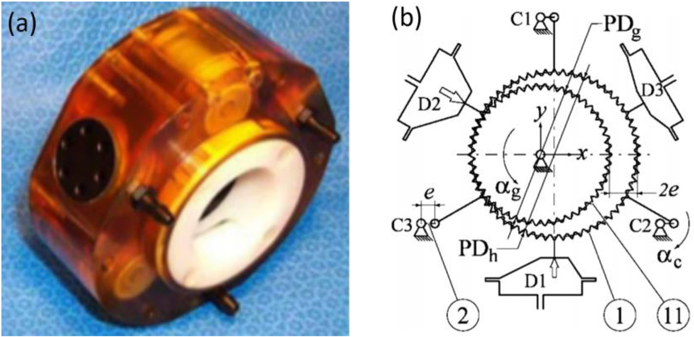
(a) PenuStep motor principle, (b) kinematics diagram of PneuStep motor.76
The advantage of the design is that simplicity of control still results in precise motion. Despite having a complicated production and assembly process, with over 20 parts, 3D printing technology has proven to be an effective approach to simplify the motor’s structure.92 The mechanical performance makes it ideal as an actuation device for an image-guided robot and other applications where low speed and high precision are required. Motor rotation angle is directly related to the number of input pulses received, and rotation speed is related to the frequency of the input pulses. The designed motor also holds its position while underloaded, without the aid of any clutches or brakes. The motor can be controlled from a remotely-located cabinet by using 7-m hoses for air and fiber optics. The hoses are fabricated from non-ferromagnetic, dielectric, and multi-imager MRI conditional materials. The precision test indicated a mean value of positioning repeatability of 0.076 mm and step interval of 5 ± 0.028° with 99% confidence. Phantom tests also showed no obvious interference in a 7-T MRI scanner with the motor powered on. Moreover, performance of the robotic systems77,78 mounted with PneuStep motor were also tested in the MRI scanner. Less than 1% SRN was reported in both applications.
Sajima Motor
A φ30-mm pneumatic stepping actuator70 was created by Sajima et al. in 2010. The stepping motion was achieved by using three direct acting gears (DA gears) and a rotational gear with 28 teeth (R gear), as seen in Fig. 3. As compressed air is applied to the DA gears, the gears rise and propel against the R gear, resulting in rotational motion. The linear motion produced by DA gears rotates the R gear with one by one engagement. When the sequential engagement is reversed, the motor produces the reversed rotation. The sequential control of the three DA gears relies on the MR-unsafe solenoid valves managing the opening and closing of air flows. Therefore, electromagnetic isolation, such as an aluminum case, is required to encapsulate the solenoid valves.
FIGURE 3.
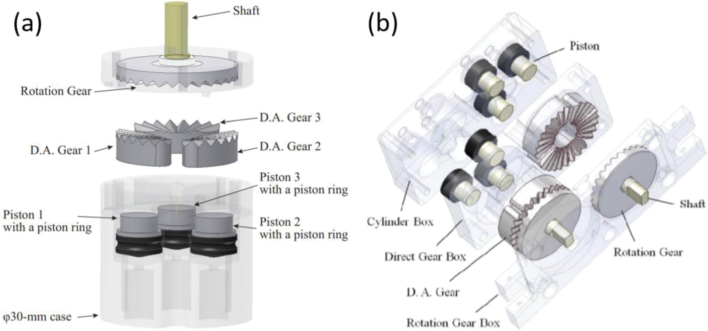
(a) φ30-mm motor parts70 and (b) assembly drawing of the φ30-mm motor.71
One noteworthy feature of this actuation is its simple structures. Compared to Stoianovici et al. design, which contains more than 20 parts, this pneumatic step motor consists of one case, four gears and one shaft. All the components can be fabricated from MR-safe and inexpensive plastics. Another remarkable feature is the high torque value achieved by optimizing the angle of gear teeth to around 40°. The torque remains high (150 mN m) though the motor is at a high rotational speed (40 rpm). The actuator’s rotational accuracy and replicability were measured, which resulted in a maximum angular error of 2.1° with a standard deviation less than the resolution of the optical encoder (0.3°) that was used in the experiment. The maximum torque was also analyzed and was found to be 150 mN m at rotation speeds lower than 40 rpm and air pressure at 0.6 MPa. MR-safety tests resulted in MRI images that were not distorted when the actuator was turned on, and SNR reduction also was not observed.
Pen-Size Motor
A compact (10-mm diameter) MR-conditional, unidirectional stepper motor was presented by Chen et al.11 This motor has the similar design with respect to the motor design by Sajima et al., but simplified the pushing component in the motor. The motor design features seven moving pieces which are pictured and listed in Fig. 4. Nonferromagnetic materials chosen for the stepper motor include an etalon guide pipe, a copper spring, an etalon pin, glass-filled nylon 66 rods and shafts. The rotation of the motor is enabled through sequentially pressurizing and vacuuming the red gear (lower push rod), which then pushes against the blue gear (upper push rod) frequently to keep the rotation. Because of the characteristics of the gears, every sequence of pressurizing and vacuuming will result in a constant 60° rotation.
FIGURE 4.
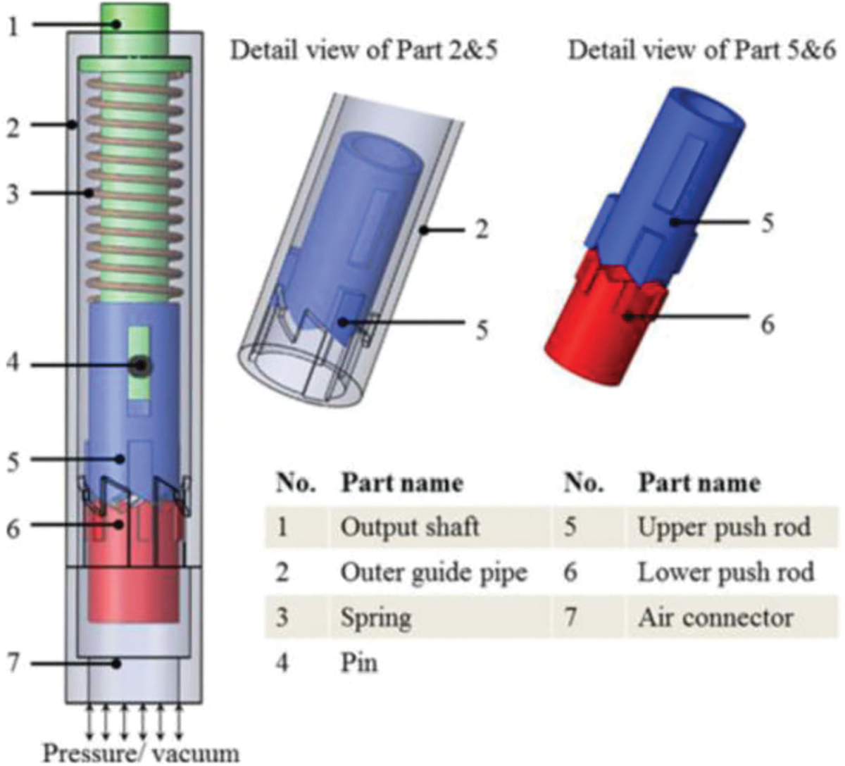
CAD drawing of pen-size stepper motor.11
The noteworthy features of this motor are its compact design (10 mm diameter), and minimal number of moving parts (only 7). The size allows it to be integrated into MR-conditional surgical devices which have strict dimensional requirements. The output torque (maximum 2.4 mN m) is a function of the spring stiffness and motor dimensions since the spring itself creates the restoring force that rotates the upper push rod and creates the torque. This is an advantage to maintaining constant speed and torque regardless of the fluctuations in air pressure. This also allows the output torque to be controlled by selecting and installing different springs. The phantom test was carried out by placing the motor at the isocenter of the MRI scanner to test its MR compatibility at the location of the strongest magnetic field. A maximum artifact width of 3 mm was produced in MR images and an SNR of 2.49% was recorded.
Stormram Motor
A three-phase, pneumatic linear stepper motor was introduced, fabricated and tested and used in Stormam series robotic systems.36 The assembly of this device employs laser-cut parts made of acrylic and acetal, which are strong and smooth for laser cutting. The principle is similar to the one developed by Sajima et al. and Chen et al., as shown in Fig. 5. The T1, T2, and T3 pistons, driven separately by cylinders, are pressed up and released down in sequence, dictating the forward or backward movement of the rack. The cylinder driving the piston requires a trapezoid-shaped seal to avoid leakage and reduce jamming. The seal is laser-cut, which introduces a kerf on the cutting edge. The MR-conditionality could be improved by experimenting with factors that affect the dimension of the kerf, such as material type, thickness, laser type, lens focal distance and focal point, cutting power, speed, frequency, assistant gas, and the local temperature.36 This motor extends its benefits in several robotic applications, including Stormram 1 to 4,1,35–37 which are specially used for breast biopsy needle manipulation.
FIGURE 5.
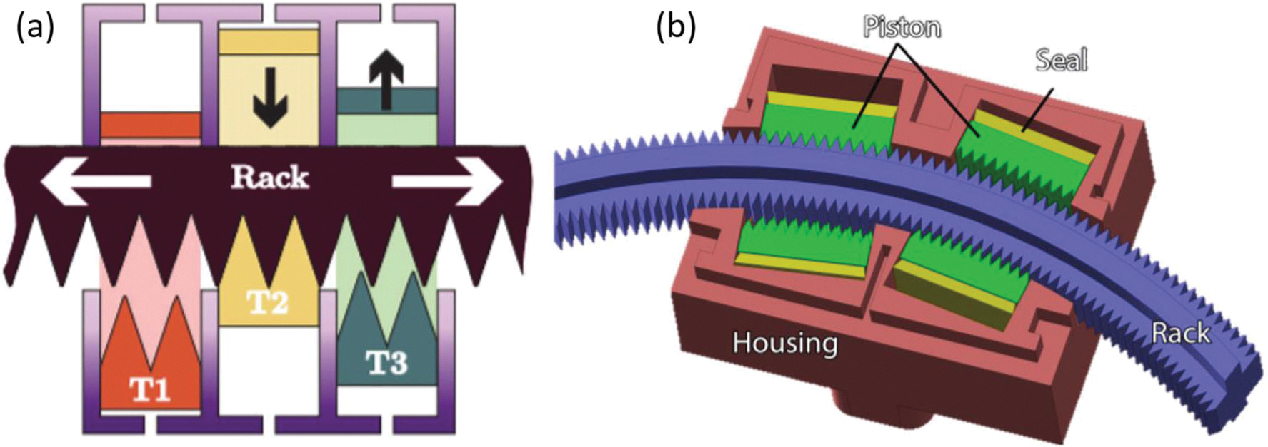
(a) Principle of Stormram linear stepper motor1 and (b) principle of Stormram curved stepper motor.35
Advantages of using this laser-cutting method to fabricate pneumatic devices are the low cost and short fabrication period for instant prototype application. Seals are cut by laser and their dimensions are iteratively adjusted to fit the cylinders. Piston teeth shape are designed to be phased 120° apart and acrylic teeth are glued to the pistons while acetal teeth snap-fit in place. The acrylic stepper motor force test showed that for the motor with 4 mm pitch size, a maximum force 24 N at the pressure of 4.0 bar was achieved. The efficiency of force transfer was 34%. However, the motor with 2 mm pitch size, the force transfer efficiency rose to 66% with maximum force 30 N at a pressure of 4.0 bar. In addition, the performance of the robotic systems1,35–37 mounted with this motor are evaluated by delivered force, operating speed, and targeting accuracy. The latest version Stormram 4 is designed to be a serial kinematic chain using a combination of linear pneumatic motor and a novel curved pneumatic motor. The accuracy of this latest version is improved to an average error of 0.7 mm. Maximum delivering force is 63 N at a pressure 0.65 MPa.
Dual-Speed Motors
The dual-speed pneumatic motors34 are evolved from Stormram linear motor, which is based on pneumatically-actuated pistons to drive a rack. The dual-speed linear design is achieved by two various-step racks aligned with corresponding pistons. Larger step size of a rack will have higher speed if the piston moving frequency is constant. Therefore, actuating the pistons will enable motor to move at the speed proportional to rack size. The working principle can be found in Fig. 6. Rearrange the four various-step racks and pistons lead to a dual-speed rotational motor. The cross configuration will enable a rotational motion when the pistons are actuated in sequence. The motor composes of several 3D-printed rigid parts (Stratasys Connex3 printer) with VeroClear material, laser-cut seals, and vaseline lubricated moving parts, the materials of which are all MR safe.
FIGURE 6.

(a) rotational dual-speed pneumatic motor and (b) the prototype of the linear and rotational dual-speed pneumatic motor.34
One noteworthy of this dual-speed motor is the high operating efficiency. It was reported that for the linear dual-speed motor, the targeting speed is one order of magnitude faster than PneuStep76 and Groenhuis’s previous Stormram linear motor.36 Because the dual-speed design equips with two different-step rack, the force delivered at the same pressure varies with the rack choice (speed). If fabricated properly, larger-step (faster) rack will have a smaller force transmission efficiency (≤ 53 N at a 0.3 MPa), while smaller-step (slower) rack will have a larger force transmission efficiency (≤ 100 N at 0.3 MPa). For rotatory motor, 74 N mm torque can be produced at a pressure of 0.3 MPa, and this can convert to a maximum force of 15 N using a rack-and-pinion, theoretically. The stepper frequency is limited to 10 Hz to avoid significant force loss. Phantom test in MRI scanner for this type of motor has not been performed yet.
Cylinder-Based Rotary Motor
The cylinder-based rotary motor10 simplifies the working principle of the pneumatic stepper motor by using a set of commercially available pistons. This motor is designed to be disposable to ensure sterilization for surgical applications. The system consists of six main components which are pictured and listed in Fig. 7. The components include the planetary gear box, supporting structure, connecting bushes, cylinders, shafts, and cranks. The cylinders, cranks, and support structure make up the crank link mechanism to allow actuation in discrete steps while the planetary gearbox is used to mechanically reduce the speed and increase output torque. The motor operates on the working principle of compressed air creating a pressure difference to provide force in the mechanism. When either cylinder is pumped with air, the resulting pressure difference moves the piston toward the lower pressure gradient, resulting in torque around the rotation center, similar to a two-stroke engine. A typical setup for the system in a clinical environment is shown in Fig. 7. Note that Secoli et al. created a similar design using the piston-based actuation72 at the same time. Due to the page limit requirement, the design will not be covered in detail in this paper.
FIGURE 7.

(a) Component of cylinder-based rotary motor and (b) working procedures of the cylinder-based rotary motor.10
The noteworthy feature of this motor includes alternating the pressurized air, which can drive the motor to rotate each step in 3.6° with the motor coupled to a planetary gearbox. The maximum torque of the motor achieved was 800 N mm. Even with its small size, the motor can generate a large output of torque while maintaining high accuracy, making it ideal for minimally invasive surgery. To test its compliance in an MRI environment, the motor was placed at the isocenter of the scanner where the strongest magnetic field is located, and the SNR and maximum width of image artifacts generated by the motor was measured. The SNR value was found to be an acceptable 2.35%.
Cylinder-Based Linear Motor
The MR-conditional pneumatic cylinders26 have the similar mechanical design and working principle with respect to the conventional cylinder, except that the cylinders are fabricated with MR-conditional materials. Glass and graphite are MR safe materials which are made for the cylinder bore and piston, respectively, although a brass shaft, which was the only metal in the prototype, was adopted. Proportional pressure regulators were placed at the end of the bed to control the air supplies for the pneumatic motor within a proper distance (5 m). The regulators were actuated piezoelectrically near the MRI environment so that safety hazard was not introduced. Pneumatic cylinders have been used for a variety of MR-conditional robot development, such as the prostate biopsy,26 brain ablation,18 liver ablation,28 etc. (Fig. 8).
FIGURE 8.

(a) Cylinder-based linear motor mechanism26 and (b) prototype of the needle placement robot.28
The cylinder-based linear motor features a fast response time (4 ms) via the careful cylinder and piston design, short pneumatic control, and proper air regulation. Forces up to 46.8 N can be applied by the cylinders while it can handle up to 100 psi. Furthermore, the design has the ability to lock the system into place in addition to moving the robot. MR-conditional brakes can be attached to the cylinders and clamped down on the brass rod to prevent further movement. An accuracy assessment of the robotic system revealed localization accuracy better than 0.1 mm and positioning accuracy of 0.26 mm over 120 point-to-point moves. The phantom study applied three standard prostate imaging protocols, which are T2-weighted turbo spin echo (T2W TSE), T1-weighted fast field gradient echo (T1W FFE), and “real time” turbo field gradient echo (TFE, or TGRE). This study validated the low interference on MRI, with SNR 5.5% for T1W FFE, 4.2% for T2W TSE, and 1.1% for TFE (FGRE).
PneuAct
The PneuAct23 proposed by Farimani et al. relies on the scotch yoke mechanism (see Fig. 9c) to convert the piston linear motion to rotational motion. Then rotation motion will transmit through a reduction drive and finally reach the expected output speed and torque. The components of this motor are shown in Fig. 9. The components of the actuator are (1) cylinder head, (2) cylinder, (3) reduction gear-head, (31) pinion gear, (32) worm gear, (4) pistons, (5) crankshaft, (6i) and the inlets.23 Three slotted links individually connect to three cranks with the corresponding piston and the reduction driver composes of a pinion gear and a worm gear. The motor was 3D-printed with ABSplus-P430 to meet the MRI safety requirement.
FIGURE 9.
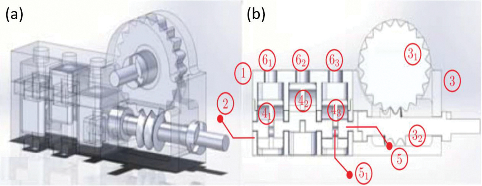
(a) Assembly drawing of the PneuAct and (b) longitudinal cross section drawing of the PneuAct.23
The primary advantage of this design is that the motor has no sealing, bearing or lubrication, which indicate the motor to be a highly affordable and disposable product for clinical use. Moreover, the stepper resolution is 3° in full-pitch drive and 1.5° in half-pitch drive, both of which are smaller than the reported 3.3° in PneuStep motor.76 The back-drivable design also allows the motor to serve in more practical scenarios. The maximum measured torque is 130 N mm at a pressure of 0.4 MPa. In the MR imaging experiments, no SNR reduction was observed in the 0.25 T MRI scanner when the motor was on, which validate the MR-conditional property.
Deformation-Based Actuation
Bellow-Based Actuator
David et al. proposed a set of bellow actuators that could create both linear motion via a toroid-shaped bellow and rotational motion via the helix-shaped bellow.18 The bellow actuation unit was designed to be a 2-DOF needle driver for translating and steering a concentric tube robot.91 The mechanism of bellow-based actuation originated from the idea of flexible fluidic actuators (FFAs) that are MR-safe and powered by working fluids such as water or air.61,63,64,94 When FFAs are pressurized, their inhomogeneity in geometry will cause heterogeneous expansion of the actuator, and thus generate bending, twisting, or rotating motions. The linear and rotary FFAs were investigated in previous works, respectively.29,69 The actuation unit includes the linear and rotary bellow actuations, linear and rotary grippers, and constraint tabs that allow linear and rotary motion simultaneously, which are shown in Fig. 10. Four control valves, two proportional spool valves, and two solenoid switch valves were designed for precise positioning and bidirectional motion. The bellow-based mechanism was fabricated by selective laser sintering (SLS) considering its complexed shapes and airtight requirement.
FIGURE 10.
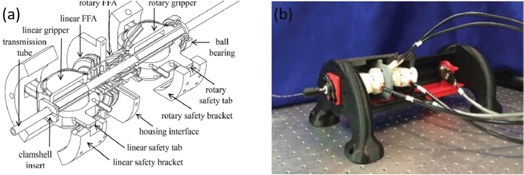
(a) assembly diagram of bellow-based actuation system18 and (b) the prototype of the bellow-based actuation system.18
Highlights of the bellow-based actuations are that it is a compact mechanism, and it demonstrates precise positioning, high insertion force, and no loss in SNR of MRI. The compact and monolithic mechanism was fabricated by cheap SLS printing, which is more economical and reliable than conventional methods.57 The precision of the positioning was achieved through the accurate fabrication techniques and the novel integration of sub- and full-step controls, achieving a steady-state error of 0.013 mm and 0.018°. The peak insertion force was 33 N, and retraction forces of − 26.5 N were tested by a force gauge (Extech 475044). The MR-compatibility test was conducted in a 3-T Philips Achieva scanner and no loss of SNR was observed when the hardware was in full motion.
Auxetic Materials Linear Actuator
A pneumatic linear actuator67 was introduced by Pfeil et al. to drive a needle for MRI-guided biopsy. The driver consists of a mobile grasper (MG), a main chamber (MC) and a fixed grasper (FG) as shown in Fig. 11b. This figure also shows the 6-phase sequence of motion, which are achieved by the elongation effect of the materials when the chamber is pressurized. Auxetic materials, which have negative Poisson ratio, are used to build the MC so that the elongation effect can be maximized. The two graspers compose of a shell made of a elastic material and a inner diaphragm made of rubber-like material, individually. Inverted honeycomb pattern, which can facilitate the elongation effect, is adopted to the outer envelope. The unit pattern and overall view of the outer envelope are illustrate in Figs. 11c and 11d.
FIGURE 11.
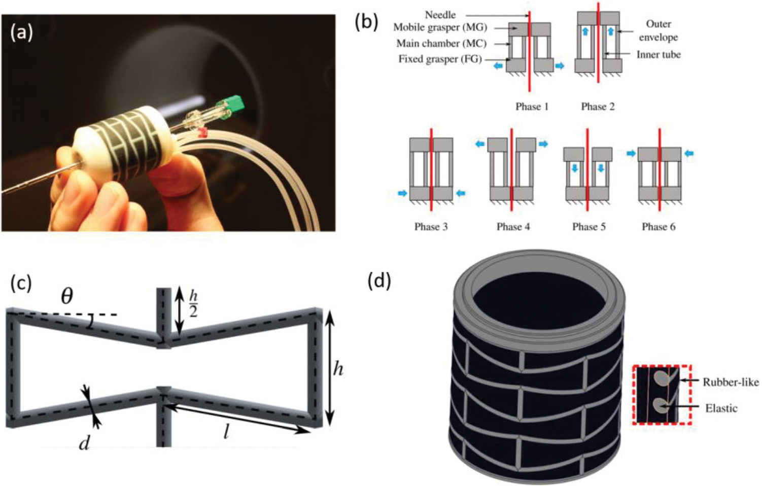
(a) prototype of Auxetic materials needle driver, (b) working phases of needle insertion, (c) envelope structure pattern unit, and (d) view of the outer envelope.67
Highlight feature of this needle driver is the small and compact design. The diameter of the envelope is 27 mm and the height of it is 25 mm. The driver can perform a 1.1 mm of insertion displacement under a 2 N load, which is the approximate resistant force of inserting a needle into human body when conducting biopsy.55 The stiffness of the driver perpendicular to the inserting axis is 16.1 N mm−1, which is 6 times of the needle stiffness to maintain stability and accuracy in the biopsy process. No artifacts or distortions were observed in the MR-conditional test performed in a 1.5 T MRI scanner.
Turbine-Based Actuation
Turbine-Based Motor
This pneumatic powered device features a continuous (non-stepwise) actuation with a custom-designed MR-safe optical encoder.12 Additionally, the motor can be fabricated using additive manufacturing and can be coupled to off-the-shelf gear boxes to meet different application requirements. The motor, pictured in Figs. 12a and 12b, has three main components: the stator, the rotor, and the cap. A planetary gearbox is integrated with the motor to allow for customizable ratios. The gearbox connects to the motor housing using brass threaded rods. The working principle of this motor involves a modified Pelton turbine which allows for bidirectional operation. This turbine-based motor converts compressed air to mechanical work by spinning a turbine with the air flow. The channels route the air flow to push the turbine blades which generates rotary motion. Motion in either direction can occur depending on which inlet the air is supplied to. This motor has been employed in multiple MR-conditional applications: microinjector system with syringe,95 MR-conditional motor with Geneva drive,96 intracerebral hemorrhage (ICH) robotic system,8 and MRI robot for prostate focal laser ablation.12,13,73
FIGURE 12.
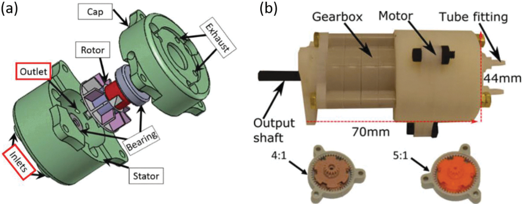
(a) Exploded view of the turbine-based motor and (b) prototype of turbine-based motor.12
Noteworthy features of this motor include a custom-built, fiber-optic encoder, the ability to be additively manufactured, and the high flexibility of gear ratios using off the shelf components. The design features high output power compared to existing designs and incorporates an encoding technique without electrical wiring while still maintaining a minimal SNR reading. Experimental testing of the motor was completed to characterize the torque, speed and power. Using a 100:1 gear ratio at 0.55 MPa, the motor was found to produce 460 N mm stall torque and 370 r/min as a no-load speed. This then corresponded to an output power of 6 W. The motor is classified as MR conditional according to the ASTM F2503 standard since it was validated in a 3 T MRI scanner and presented no hazard in the environment. The SNR evaluation resulted in values less than 5%.
Fan-Based Motor
Wei et al. proposed a fan pneumatic motor92 in the hope to address the assembling complexity of the PneuStep.76 The working principle of this motor is similar to a wind turbine. Four inlets of air are designed to achieve bi-directional rotation. This motor only has three primary parts: a shell with inlet holes, a fan motor, and a geared arm, which is shown in Fig. 13a. A roller and corresponding roller valve that is controlled by air is also designed for mode shifting: natural mode, modulated mode, and stepper mode. As shown in Fig. 13a, the red roller can be controlled by roller valve so that it can gradually “brakes” the fan motor as the roller valve opens. While the motor can be controlled by the roller valve, it will become a stepper motor when the valve opens at its maximum, resulting in the mode shifting. All the parts are 3D printed with the material VeroClear 950.
FIGURE 13.

(a) assembly drawing fan-based motor and (b) the prototype of the fan-based motor.92
One of the distinguish characteristics of this motor is that this motor adopts easy-to-assembly joint that significantly reduces the manufacturing process, and all the parts are carefully designed to accommodate the 3D printing manufacture error without compromising the stability and reliability of the mechanism. Although no MRI phantom test has been performed on this motor, it is promising to be used in MRI-guided surgical device because all the materials are MR-safe. This motor achieves the rotary speed of 36 rad/s and the torque 12 N mm at the pressure of 0.15 MPa.
Piezoelectric Motors
The Piezoelectric motors rely on geometric change of a piezoelectric material to create the motion when supplied with electric field. This actuation method converts electrical energy into mechanical energy at the point of actuation through small cables, and produces high voltages and low currents while operating. Piezoelectric motors have been widely used in MRI-guided robotic systems due to their accuracy, reliability and self-locking capability.2,15,27,50,56,83,84 Since electric motors are not MR-safe, additional RF shielding and driving circuit control may be needed to ensure the actuator is safe for both the patient and operator. Compared to the pneumatic actuator, the primary limitations of piezoelectric motors are high cost and, most importantly, the need to disconnect the power during image acquisition to prevent image distortion due to magnetic fields caused by the electrical conductors.27,49 Recent results show that better imaging quality can be achieved with custom-designed piezo actuator drivers and control methods which are not commercially available yet.25,40 One of the factors that disturbs the MRI signal and causes reduction of SNR is the unexpected waveform generated by standard driving circuitry.17,21,90 Researcher Gregory S. Fischer was successful in diminishing the SNR reduction with his invention of a ceramic motor driver system for the HR series actuators, which achieved an average 5% reduction of SNR under T2 imaging and no more than 10% in the whole test.25
USR Series (Shinsei Corporation, Tokyo, Japan, and Fukoku Co., Ageo-shi, Japan)
USR motors are one of the most welcomed piezoelectric rotary motor series which were reported in multiple applications of MR-conditional robotic systems, such as MR-SoftWrist75 and Neurosurgery Robot.60 Typically, they are utilized in the scenarios where high-speed motion is required. The technical data is summarized in Table 2.
TABLE 2.
USR series motor summary.
| Type | Technical data | |||
|---|---|---|---|---|
|
| ||||
| Speed (rpm) | Torque (N mm) | Holding torque (N mm) | Size (mm) | |
|
| ||||
| USR30-B3/4 | 250 | 50 | 100 | 30 × 40 × 25/44.5 |
| USR30-S3/4 | 250 | 50 | 100 | 36 × 44 × 30/44.5 |
| USR60-S3/4 | 100 | 500 | 1000 | 67 × 77 × 47.5/60 |
| USR30-E3(T) | 250 | 50 | 100 | 36 × 50 × 48 |
| USR60-E3(T) | 100 | 500 | 1000 | 67 × 77 × 66 |
MR-SoftWrist, as illustrated in Fig. 14a, consists of (1) wrist ring, (2) universal joint, (3) link, (4) handle, (5) extension spring, and (6) ultrasonic motor.22 Materials of the MR-SoftWrist include delrin for structures, brass screws, linear series elastic actuations using USM (USR60E3NT, Shinsei), a pulley, and custom brass extension springs. Aluminum foil was wrapped around encoder cables and USMs incorporated with an additional outer Faraday shield to avoid electromagnetic interference.
FIGURE 14.

(a) Configuration of MR-SoftWrist, (b) phantom test in scanner room, and (c) robot end effector DOFs.22
The phantom test is conducted as shown in Fig. 14b, where (7) is the encoder and power lines, (8) is the MR-SoftWrist robot, (9) is the subject, and (10) is the visual display of measured and desired position. Position accuracy testing indicated a root mean square error of 2.25° and maximum error of 3.45°. Force measuring showed that the force can reach 8 N in direction and torques of 460 N mm and 630 N mm in and directions (as described in Fig. 14c), respectively. MR-conditional tests were conducted on a gel phantom in another relevant publication suggesting a 6% reduction of SNR in the worst case of 3 T phantom experiments.24 The USR motor has also been used in 7-DoF neurosurgical robot60 and demonstrated promising results in terms the accuracy and SNR reductions.
HR Series (Nanomotion Ltd., Yokneam, Israel)
HR motors are prevailing piezoelectric linear motor series which were reported in the research. They are typically used as linear motion motors where high speed and moderate force are required. The technical data is summarized in Table 3.
TABLE 3.
HR series motor summary.
| Type | Technical data | |||
|---|---|---|---|---|
|
| ||||
| Speed (mm/s) | Stall force (N) | Holding force (N) | Resolution (nm) | |
|
| ||||
| HR1 | 250 | 3.5 | 3.5 | 100 |
| HR2 | 250 | 7 | 7 | 100 |
| HR4 | 250 | 15 | 14 | 100 |
| HR8 | 250 | 30 | 28 | 100 |
Transrectal prostate robot50 is one of the robotic system employed HR series motors. Several research studies and tests about the HR Series motors have been conducted, especially on the MRI-based needle insertion. Access to prostate tissue under MRI Guidance is one of the applications using piezoelectric motors, and its structure is shown in Fig. 15.
FIGURE 15.
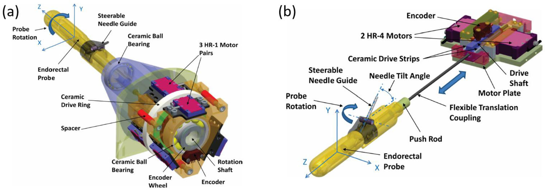
(a) APT-III actuated robot with rotation stage and (b) APT-III actuated robot with translation stage.50
The accuracy of this robot is well noted. With three pairs of HR-1 motors mounted on a rotation stage and two pairs of HR-4 motors on a translation stage, the robot achieved an average error of 2.4 mm and a maximum error of 3.7 mm in the accuracy study during phantom test, which is sufficient for prostate surgeries.50 However, the phantom test also showed that when the motor was on, the SNR would reduce 40%–60% under T2 imaging even if equipped with radio-frequency shielding to shield the standard MR conditional cable between robot and controller.50 Therefore, the MRI scanning process and surgical operation cannot work simultaneously. As a result, intraoperative imaging is carried out while the robot is not operating, which could potentially affect the efficiency of surgical workflow.
PiezoMotor (Uppsala, Sweden)
PeizoMotor provides both linear and rotary piezoelectric motors, several of which were reported in the MR-conditional robotic research, such as the needle placement robot,40 the concentric tube robot,81 and body-mounted robot.56 They are typically used for the scenarios where motors require high force or torque and moderate speed. The technical data is summarized in Table 4.
TABLE 4.
PiezoMotor motor summary.
| Function | Type | Technical data | |||
|---|---|---|---|---|---|
|
| |||||
| Maximum speed | Stall force or torque | Holding force or torque | Step length | ||
|
| |||||
| Linear motion | LL06 | 24 mm/s | 6 N | >6 N | 4.5 μm |
| LT20 | 24 mm/s | 20 N | >20 N | 4.5 μm | |
| LT40 | 12 mm/s | 40 N | > 40 N | 5 μm | |
| LTC40 | 12 mm/s | 40 N | > 40 N | 5 μm | |
| LTC300 | 0.3 mm/s | 30 N | 28 N | 4 μm | |
| LTC450 | 0.2 mm/s | 450 N | > 450 N | 4 μm | |
| LS15 | 12 mm/s | 15 N | >15 N | 4.5 μm | |
| Rotary motion | LR17 | 44 rpm | 30 N mm | > 30 N mm | 1000 μrad |
| LR23–50 | 27 rpm | 50 N mm | > 50 N mm | 550 μrad | |
| LR23–80 | 27 rpm | 80 N mm | > 80 N mm | 400 μrad | |
For the needle placement robot,40 it is comprised of a 3-DOF needle steering module and a 3-DOF Cartesian positioning module as illustrated in Fig. 16a made from acrylonitrile butadiene styrene (ABS) and laser-cut acrylic. A collet mechanism was adapted to fasten and lock the needle on the robot steering module, while a brass spring was designed to preload the needle. Non-harmonic piezoelectric motors were selected as the actuators of this robot and the tracking fiducial frame (Beekley, Bristol, CT) was embedded in the robot system for navigation purposes.
FIGURE 16.
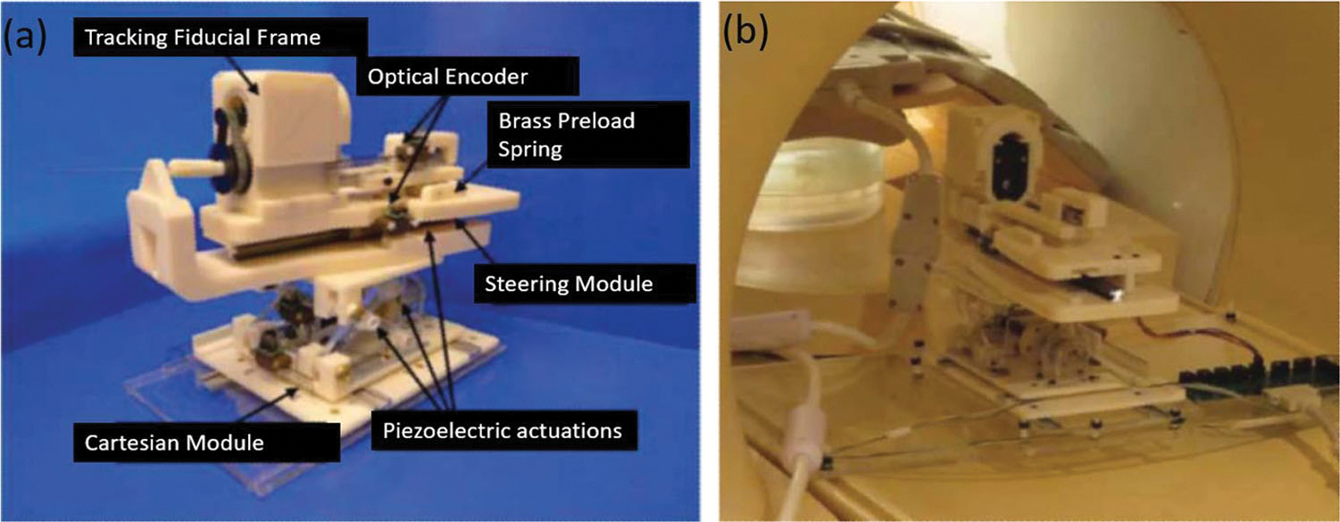
(a) Needle placement robot configuration and (b) phantom test installation.40
The most noteworthy features of this robot are the real-time needle manipulation and low interference with MRI. The end effector (needle) navigation of the robot relies on the fiducial frame, which measures in real-time the transformation of coordinates between patients and the needle.26 Thus, the positional relation between needle and patients will be explicit. A novel, low noise electric board was developed to reduce the interference of MRI. Non-harmonic piezoelectric actuators on this robot also take the advantage of easier electric wave suppression. The 3 T phantom study validated that the SNR reduction was negligible when the motor is powered off during the scanning. Other mechanisms that used this motor include an MR-conditional concentric tube robot for neurosurgical application81 and body-mounted robot for arthrography procedures.56 Due to the SNR reduction that caused by these piezomotors when they are ON, during the MRI scanning the motors should be turned off.
Piezoworm
A compact piezoworm (or inchworm®) actuator was designed for an MRI environment to provide both linear and rotary motion.20 The main design objectives for the actuator were high thrust and torque, long linear travel range, high stiffness, and minimal size. In order to maintain high stiffness and minimize image interference, beryllium copper was used as the material of choice. A piezoworm-type actuator, which combines several piezostacks, is utilized in the design. The actuator is shown in Fig. 17. The configuration of the piezoworm allows two piezostacks to be clamped to the shaft, with a third to provide linear motion and a fourth piezostack to obtain rotary motion. The same set of clamps can be used for each type of motion which helps reduce the overall size of the actuator. One clamp (NU) is used to grip the shaft when the piezostack is energized and the other clamp (NC) grips the shaft when the piezostack is de-energized. Motion can be completed separately or jointly since separate actuators are used for each degree-of-freedom.
FIGURE 17.
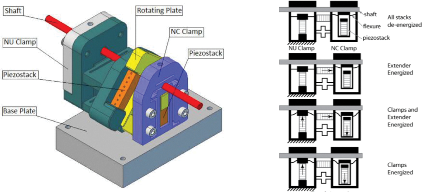
Piezoworm actuation model.20
An advantage of this design is that only four actuation operations are required, compared with a conventional piezoworm which is completed in six successive actuation operations. This economy is because both clamps are supplied by one signal amplifier which allows one clamp to open while the other clamp closes. This clamp design also allows the shaft to be secured in place safely in the event that a sudden power loss occurs. The speed of both linear and rotary motion is controlled by the amplitude and frequency of the voltage waveforms. At the time of writing, a prototype was being developed to perform tests and to test MRI compatibility. The expected maximum speed of the motor is 9 mm/s while using a driving frequency of 800 Hz. Similarly, the expected output torque is expected to be 5 N mm using a driving frequency of 800 Hz.
Hydraulic Motors
The hydraulic motors are typically powered by an electric motor or regulators that pressurizes the working fluid and transfers the dynamic force to the hydraulic motor at distance. The hydraulic tube, the hydraulic motor, and the diaphragm can be produced using non-ferromagnetic materials. Because MR unsafe electric motors and their accessories are placed at a safe distance from the MR scanners (i.e., MR control room), hydraulic actuations can be used for driving MR-conditional robots.30,32,47
Similar to the pneumatic actuators, the MR-compatibility performance of hydraulic actuation purely depends on the materials properties that being used to construct the actuator since its working principle is electro-magnetically decoupled from an MR scanner. There are certain drawbacks to hydraulic actuators. One major limitation is safety concerns around higher pressures and fluid leakage. Introducing an external, high-pressure fluid into a sterile operating environment poses significant risk to the patient. Significant testing must be completed in order to ensure fluid leaks are minimized, and that there are procedures in place to ensure patient safety if a leak did occur during a procedure. Another limitation is managing the friction that occurs at the joints and within the fluid, which could affect the actuator performance and change as components begin to show signs of wear. Finally, current use of hydraulic operations in hospitals is minimal when compared to compressed air. This results in a larger cost when equipping and preparing operating rooms to use the robot. More maintenance is required in order to keep a hydraulic system continuously running, and periodic fluid changes result in operating damages.
Master–Slave Hydraulic Actuator
The hydraulic actuation developed by Lee et al. consists of a slave unit, a hydraulic tube, a master unit and an actuation motor outside of the MRI room.52 The proposed hydraulic motor utilizes a master–slave hydraulic transmission mechanism to ensure MR compatibility of the robot actuation. As illustrated in Fig. 18, the master units, located outside of the MRI room, control the hydraulics with electric stepper motors and pistons and serve as the source of hydraulics. The slave, located in the MRI room consists of two rack-and-pinion units to transfer motion from linear to rotary. The hydraulic fluid is transmitted to actuators of the slave robot in the MRI room through 10-m-long hydraulic pipelines.
FIGURE 18.

Principle of the master–slave hydraulic actuator.52
One advantage of such design is that this master–slave actuation system has great potential for high-performance (large torque) actuation under MRI without adversely affecting imaging quality (SNR loss < 2%). The hydraulic force transmission efficiency is 70% at the pressure of 0.1 MPa, creating a torque of 1470 N mm and net power of 2.93 W. Minor hysteresis and quick responses were also noteworthy. In the hysteresis test, a sinusoidal trajectory output was tested with a PID controller at the frequency of 0.1 Hz, and a maximum hysteresis error of 0.67 mm was observed. The dynamic responses lag was 66 ms at frequency of 15 Hz. This response lag results from the deformation of both fluid and tube when transferring the force. Robotic systems with this actuation method have been developed for multiple applications: the intracardiac catheterization robot,52 the bilateral stereotactic neurosurgery,39 the three-cylinder actuated catheter manipulator,19 and the needle robot with soft fluid-driven actuator.41
Hydraulically-Actuated Revolute Joint
The idea for hydraulically-actuated revolute joints66 stems from compliant mechanisms that allow robots to be compact and monolithic.5,16,97 A helical shaped compliant (HSC)6 joint is one of the compliant mechanisms which was deployed in the design of the hydraulically-actuated revolute joint. As presented in Fig. 19b, the gear rack inputs force and velocity to the helical shape (volume 1), which is coupled with a similar helical structure (volume 2) with opposite pitch to the first. Between the two helical shapes is a rubber-like material (black block with a size e on the center of Fig. 19a) allowing rotation of volume 1. The gear rack is actuated through hydraulic pressure in a piston-and-cylinder mechanism. Figure 19c clarifies the whole picture of the hydraulically-actuated revolution joint. The materials used for fabricating the joint are rigid polymer (volume 1 & 2) and TangoBlack Plus (a rubber-like material). Multi-material additive manufacturing (MMAM) was used to combine rigid and soft materials with the leeway of shape adjustments.
FIGURE 19.
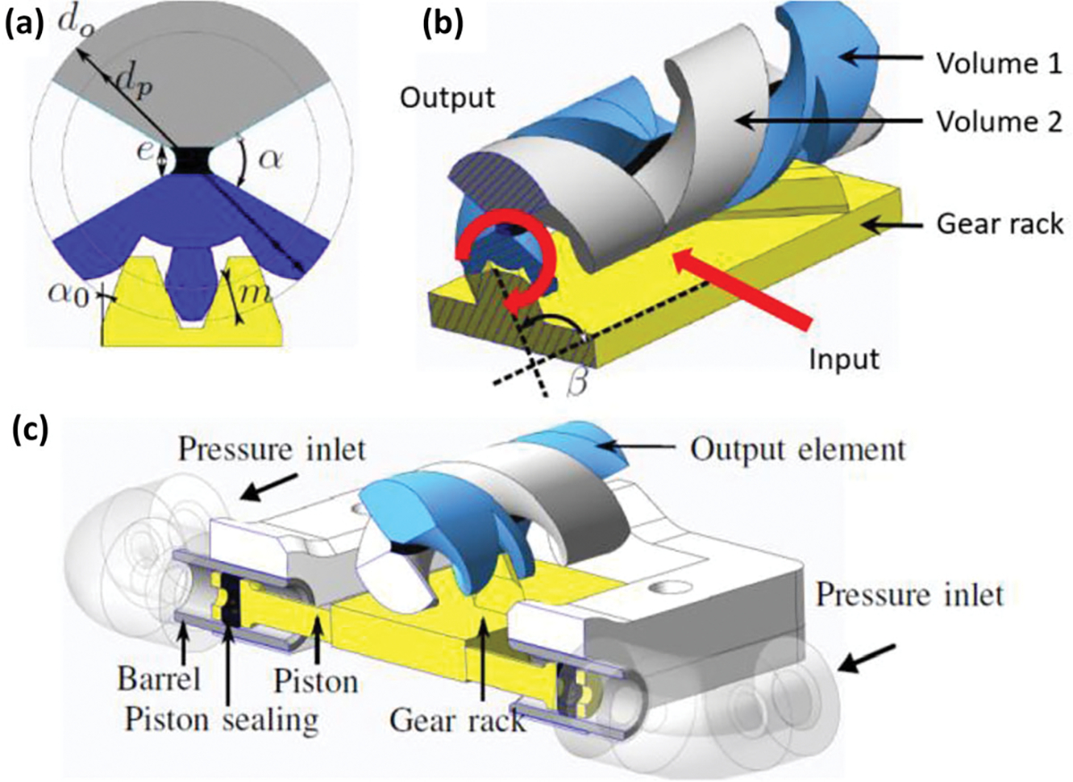
Cross-sectional view (a) and working principle and (b) of the HSC joint with embedded rack-and-pinion system. Assembly of hydraulically-actuated revolute joint (c).66
Benefits of this revolute joint are compactness, mechanical efficiency and transmission accuracy. Integration of a helical shape with a gear rack reduced the complexity of traditional methods to convert cylinder translation into a rotation.39 The MMAM process also provides an opportunity for compact joints to be designed and fabricated.23 Mechanical efficiency is improved by the non-frictional based design. The helical gear and rack design ensure the transmission accuracy. For the hydraulic piston actuation, the piston friction was evaluated using a laser-based sensor (optoNCDT 1420, MicroEpsilon), a linear table (FB075, Nanomotion) and a force sensor (K1107, SCAIME). The results indicated the best actuator force achievable is 87% (2.5 N friction force while induced 18.4 N theoretical force) of the theoretical maximum force.
Hybrid Hydrostatic Actuator
A hybrid air–water based actuation method93 was introduced by Whitney et al. to enhance the working load while reducing transmission impedance. The hybrid actuator7 and transmission system was implemented with N hydraulic lines and 1 pneumatic line for the N degrees of freedom system (similar to N + 1 tendon-driven transmission), with piston-based actuations placed at the end of each line for the power transmission purpose, while rolling diaphragms were adopted to seal the hydraulic cylinder piston with O-ring seals or cup-seals. An IER Fujikura diaphragm (part number DM3–20-20, 24 mm stroke for 20 mm bore cylinder) was assembled in the prototype shown in Fig. 20. Cylinder rods were carried by a pair of belts so that they were able to move exactly tangent to the belt pitch.
FIGURE 20.

(a) Working principle of rolling diaphragm cylinder: A is the principle of the cylinder, B is IER Fujikura DM3–20-20 diaphragm and molded-in O-ring at the base, (b) hydrostatic transmission: one air line (red) and one water line (blue) are connected to the actuators for 1-DOF robot, (c) prototype of the hybrid hydrostatic actuator.93
One distinct advantage of this actuation method is the low impedance, which is achieved with rolling diaphragms assembled on piston O-ring seals that smooth the movement between the cylinder and piston with zero leakage. The low pressure required for the rolling diaphragms is still sufficient for surgical use. Water, which has low viscosity and incompressible characteristics, is more effective than oil in this application, for improving transmission stiffness and fluid damping. This cylinder actuation can deliver a maximum torque of 4500 N mm and 135° range of motion, and only weighs 120 g. Hybrid lines (water lines and air lines) were introduced to preload the hydraulic lines, reducing the number of bulky hydraulic lines. The configurations of hybrid lines are in Fig. 20b. In contrast to traditional mechanical springs being used to preload the lines and bring in additional damping and inertia, compressed air-filled lines work as air springs that are adjustable and store energy efficiently. The ability to instantly change the preload pressures or de-energize the actuation are also desirable for surgical operations.
Others
Shape-Memory Alloy Actuator
Shape-memory alloy (SMA) actuator consists of an alloy that can retain its previous form and return to its pre-deformed shape when heated.43 The actuator was designed to mitigate slow response times, a common issue affecting SMA-driven systems. The SMA spring-actuated robotic system was been developed with active water cooling to enable real-time control of SMA spring actuators. Upon completion of an actuation cycle of the SMA actuator, air is introduced to remove the water from the system prior to the subsequent actuation cycle. This circulation system consists of a water reservoir, air compressor, valves and wye fittings used to alternate the flow during the heating and cooling processes. Three versions of SMA actuation, as shown in Fig. 21, have been designed, fabricated and evaluated: the MINIR,62 the MINIR revised,42–44 and the MINIR-II.14,46
FIGURE 21.
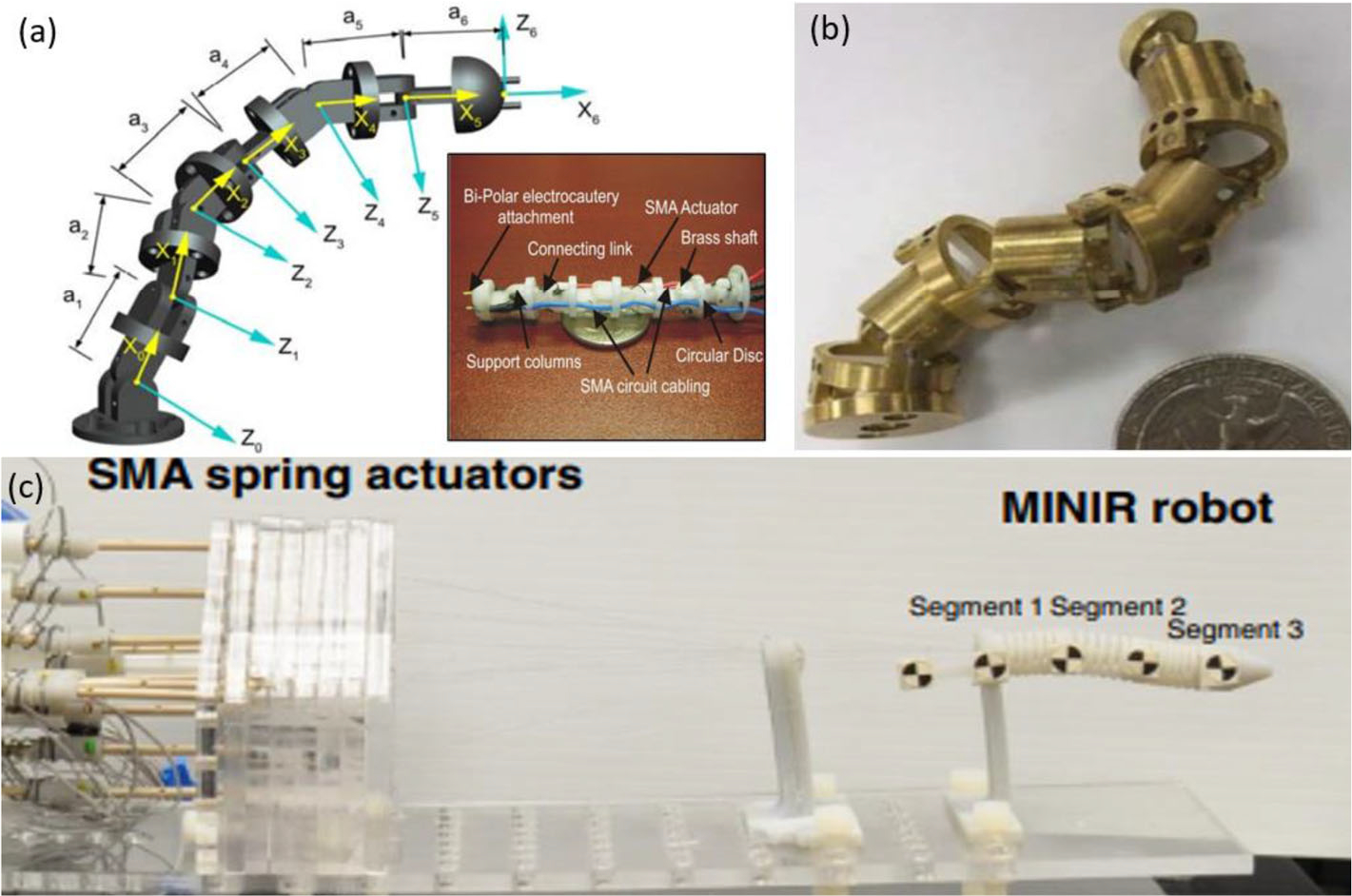
(a) MINIR prototype, (b) MINIR revised prototype and (c) MINIR-II prototype.42–44
SMA has several benefits over other conventional actuators like hydraulic and pneumatic actuators, including high power to weight ratio, compact size and silent operation. An SMA approach no longer requires inspections of parts, potential for fluid leaks, cavitation or delay due to long transmission lines. SMA’s have a low cost and higher actuation force which makes them a competitive actuator device when compared to other methods. Experimental results showed that the SMA mechanism provided a consistent average robot speed greater than 1 mm/s, and that the average speed of the robot improved with larger SMA spring displacement. Both air and water were tested as cooling media for the actuator and it was determined that the robot speed with water was more than double than when air was used. Extensive study of the relationship between the joint-space displacement and temperature was performed, which allows the robot to be control with Pulse Width Modulation (PWM). The maximum accuracy was reported to be 5.5°, resulting in a 0.69 mm error in displacement. Maximum 1.5 N force was measured when one of the SMA wire was actuated. The SNR reduction was evaluated in a 3 T MRI scanner and 10% was observed.
MR-Powered Motor
This motor design features a compact and wireless assembly with actuators that are powered and controlled by the MRI scanner.88 The main principle of operation relies on ferromagnetic bodies that are embedded in the actuator to convert the electromagnetic energy from the MR scanner into useful mechanical energy. The ferromagnetic bodies can be placed outside of the imaging region and be constrained within a small volume such that it does not affect the image quality. The actuators are also wireless which makes the integration of the system simpler. The motor consists of a stator and a rotor. The rotor has a ferromagnetic object enclosed in a cavity inside of a lever arm which rotates a fixed distance about an axis. In order to provide maximum torque, the cavity must be located at the maximum possible moment arm. Additionally, friction between the ferromagnetic body and the walls of the cavity is minimized by optimizing the geometry of the ferromagnetic body, see Fig. 22 for the detailed motor design.
FIGURE 22.
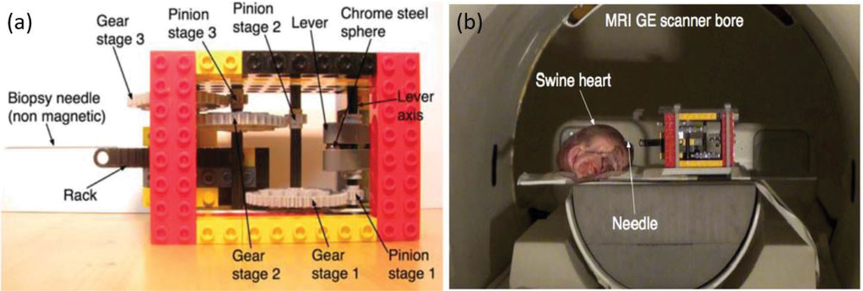
(a) Assembly of MR-powered actuation and (b) phantom test of the robot system.88
The actuator does not affect the image SNR within the imaging region because the ferromagnetic material has a small volume and is located outside interest region. Three experiments were conducted inside a GE 1.5 T MRI scanner to validate the concept and analysis. The first experiment estimated the friction present within the actuator. The second experiment tested if the set up could puncture a swine heart. At 20 mT/m the needle was unable to puncture the heart, but increasing that to 40 mT/m allowed the needle to penetrate to a depth of approximately 15 mm. The last experiment tested the locking mechanism of the motor. A bar that pivots around its center of mass was used as the locking mechanism. Small gradients are then used to rotate the bar between the locked and unlocked position which prevents the actuator lever from rotating. The maximum force was reported to be 0.76 N.
Elastic Actuator
A Bowden cable-actuated, series elastic actuator (SEA) was designed with ideal bidirectional compatibility.74,98 It was targeted to be a low cost, torque controlling, MR-conditional actuation method. The initial design was for use as a single DOF wrist device. The actuator structure consists of three main parts made from plastic materials: support, exterior shell, and output shaft. These parts are illustrated in Fig. 23. The support provides the base on which the rest of the components are assembled. Ropes that run through the plastic case are used to actuate the exterior shell. The output shaft is then connected to the exterior shell through the plastic leaf springs. An encoder incorporated into the design measures angular displacement and velocity of the exterior shell relative to the support, and a second encoder measures the deflection of the output shaft relative to the exterior shell. Both the sensor processing unit and the actuation device are situated outside the MRI room since fiber optics allow data to be transferred long distances and the Bowden tubes allow for power to be transferred from the motors to the MRI device. Decoupling the actuation unit as previously described ensures bidirectional compatibility and also reduces the weight of the device from 15 to 0.3 kg. The prototype was selected to have a 200 W DC motor coupled to a harmonic drive having a gear ratio of 1:50. With the use of a pulley, a 1:223 transmission ratio can be achieved between the external shell and the DC motor.
FIGURE 23.

(a) Exploded view of MR-conditional SEA and (b) the robotic system prototype.74,98
A unique aspect of this design is the Bowden cable-driven series elastic actuation that powers the actuator. The Bowden cables allow for bidirectional MRI compatibility by allowing the controller and actuator to be located outside the MRI room. The high friction in the cables and harmonic drive creates a non-back drivable power system. Series elasticity is introduced between the cable-driven exterior shell and the output link, which ensures better torque control and reduces the output impedance of the system. SEA offers higher compliance of its sensing unit when compared to previously-used conventional torque sensors, which results in higher torque controller gains without affecting the stability limits. Low cost transmission and actuation units can be implemented in the design of SEAs to reach higher torque control since controllers with higher gains are more responsive and robust when it comes to disturbances. Tracking experiments for a sinusoidal reference signal to control the torque was performed and the RMS error of 4% was reported.
Electrostrictive Polymer Actuator (EPAM)
EPAM has distinct shape changes between actuated state and relaxed state, which can be used to reconfigure MRI surface-imaging coil (RMIC) to the desired shape.89 This device is known as “digital mechatronics” because the binary polymer performs similarly to the digital boards. The single EPAM, as shown in Fig. 24a, contains active region, RF signal carrier, and film which are concentric to each other. The actuator will expand the active region to generate shape changes by activating the dielectric film. While single actuator cannot have universal change but only concentric shape change, modulus design is introduced to integrate several independent single EPAM into a multi-actuator modular design as shown in Fig. 24b. Every single EPAM can be activated independently so that the shape of rectangle coil can change accordingly, allowing for control of 24 shapes.
FIGURE 24.
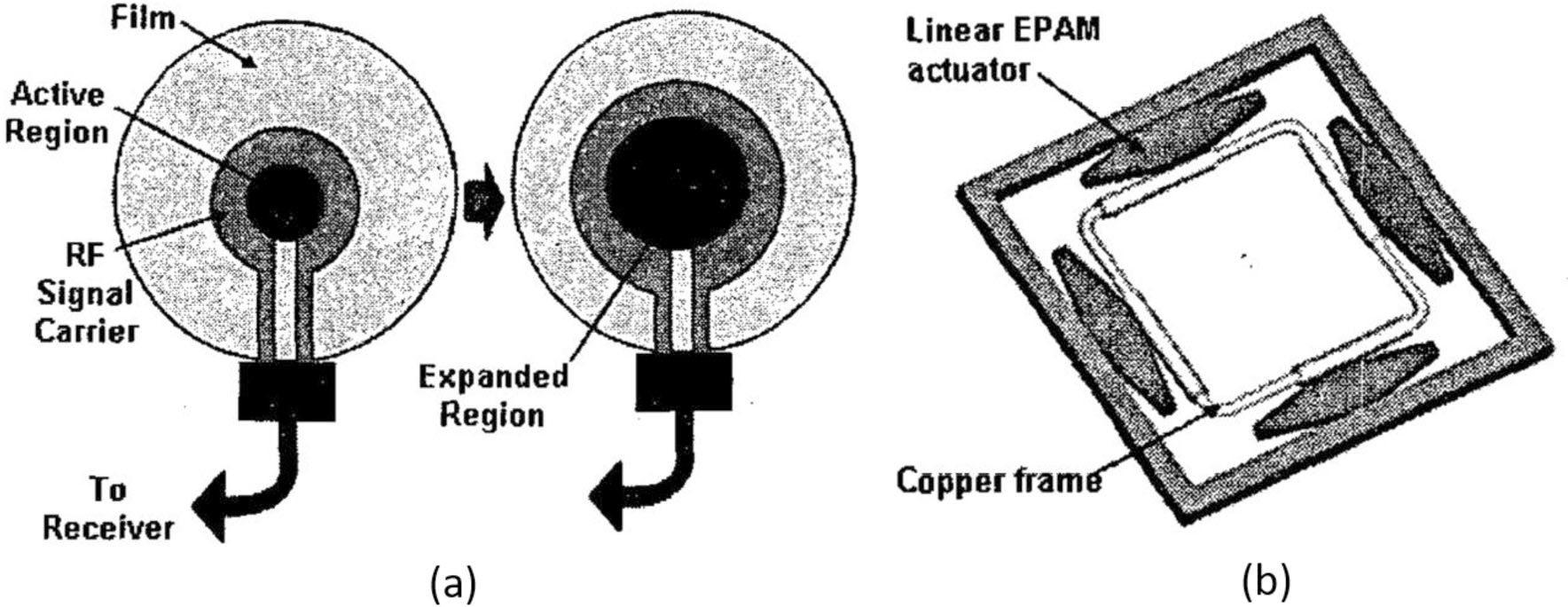
(a) The single actuator integrated cod design and (b) the multi-actuator modular coil design.89
Noted feature of this device is the ability to change shape at 4 directions of the coil, leading to maximum 270 times area expansion. Compared with piezoelectric actuators, the device is simple and inexpensive to build. And the experimental result shows the compatibility of this actuation.
DISCUSSION AND FUTURE WORK
There is significant growth in the field of MR-guided interventions in the past three decades due to the wide availability of interventional MRI (iMRI) scanners, especially in the academic medical centers. The global image-guided therapy market was valued at $3.02 billion in 2017 and is expected to expand at the rate of 6.3% per year.33 MRI-guided therapy systems constitute the second-largest product segment representing a significant market, which includes the MR-guided neurosurgeries, prostate therapies, cardiac ablation therapies, etc. Compared to the conventional robotic therapies guided by CT or Ultrasound, the MR-guided robotic interventions have the capability of leveraging the unique advantages provided by MRI scanner, which includes the high-resolution soft tissue imaging, accurate tissue property characterization, ablation temperature monitoring, no ionizing radiation, and brain activity monitoring via fMRI. One of the primary active research areas in MR-guided robotics is the investigation of the motors that could safely actuate the robot within MRI environment. In addition, the fact that most of the MR-conditional actuation parts are built free of metallic components allows those robotic systems to be conveniently guided by conventional imaging technology (CT or Ultrasound), although a few MR-conditional materials can cause artifacts and distortions in CT imaging as reported in Klinke et al.48 However, for the engineering aspects, the MR-conditional materials which is not compatible to CT are not necessary choices and can be replace by a variety of alternative materials which are compatible to both CT and MRI. For ultrasound guided actuation, the materials of actuator should avoid ultrasound absorbing material such as polystyrene, polyurethane rubber, syntactic foam, etc.68 Those materials are not common on MR-conditional actuation, but hydraulic actuator may be not applicable to use under ultrasound because water is also ultrasound absorbing material. Despite several incompatible materials to CT and Ultrasound, most of the MR-conditional actuations can be versatile and convenient to integrate into other imaging technologies.
From the authors’ perspective, motor reliability, dynamic performance (i.e., torque, power, and speed), and cost are the primary considerations in choosing and developing the MR-conditional actuators. Due to the difficulty of effectively fabricating the piezoelectric actuator in the research labs, the prior researchers typically choose the commercially available piezo actuators to power the MR-guided robotic systems. The piezoelectric actuator demonstrated the best performance in terms the motor reliability and most of the system dynamic indices. However, RF shielding of these motors are needed to ensure the MR-compatibility requirement, which typically has a complicate physical wiring and cumbersome use in the MRI room. Despite the recent advance in the novel piezo motor drivers design,25 the RF shielding is still necessary for both piezoelectric motors and cables. Improper shielding will lead to image quality degradation and SNR reduction, especially when the motor is powered during MRI imaging. In addition, the cost of these high-performance piezo motor is another limitation since each motor and related drivers could easily cost over $1000. Thus, this could potentially limit its wide implementation in the academic communities, especially during the robot prototyping period.
Different from the piezoelectric actuators, the custom-designed pneumatic motors, hydraulic motors, and other MR-conditional actuation methods have certain advantages in terms of the dynamic performance and cost-effectiveness. Pneumatic driven actuator is the predominant research topic in the field of MR-conditional actuators, as evidenced by the number of the related papers published in the past 15 years. With the advancement of additive fabrication technique, the MR-conditional pneumatic actuators can be easily prototyped with a low-cost 3D printer. Depends on the materials to fabricate the motor or the required accessories (i.e., encoder, pneumatic fitting), these 3D-printed MR-conditional pneumatic actuator could also meet the MR-safe requirement. Coupled with different types of reduction mechanisms, the dynamic output of these pneumatic actuators could meet various requirements. In addition, since these motors are typically fabricated with 3D printing or laser cutting technique, researchers can easily tailor its geometric configuration to meet the specific design requirements. For example, an MR-conditional neurosurgical robot that can be operated within the bore pose enormous dimension restrictions compared to the robot that operated outside the MRI bore, such as the prostatebiopsy robot. Another benefit of using pneumatic driven actuator is that compressed air supply is typically available within the standard clinical environment and the exhausted air can be released to the environment without causing any hazards to both patients and surgeons. Hydraulic driven actuators share the similar working principle of the pneumatic driven actuators, but with the incompressible liquid rather than the compressed air supply. Compared with the pneumatic driven actuators, hydraulic actuators have the advantage of better dynamic performance (i.e., torque, power) and higher operational bandwidth. Due to the incompressible characteristic of the fluid, the hydraulic actuator maintains the consistent dynamic behavior even when the fluid hose is considerable long. This can be extremely beneficial to address the MR-compatibility issue by simply placing the MR-unsafe hydraulic pumps in the MRI control room. Both pneumatic and hydraulic driven actuators suffer from the limitations of the system reliability. For example, life cycle of the 3D-printed plastic pneumatic actuators has not been systematically analyzed yet. The hydraulic fluid leaks inside the MRI scanner can lead to sterilization challenges and even damage the MRI scanner. For the other MR-conditional actuators, such as SMA and MR-powered approach, they demonstrated certain advantages over the conventional motors, but also pose significant hazard in terms of the heating and safety, respectively. Bowden cable actuated approach does not pose safety or image quality hazard, but the electric encoding devices are required to measure the joint space input. However, the long transmission easily enables master–slave operation when the actuation source is located in the control room.
Although a variety of the state-of-art MR-conditional actuation methods have achieved the basic requirements such as high actuation accuracy and low SNR reduction, most of them are not ready to be used for in the clinical settings. In addition to meet the basic technical requirements, future MR-conditional actuations should consider how to create the robotic systems that could fit seamlessly into the current surgical workflow in the operating room. From the authors’ perspective, it is a challenging task to reduce the actuator dimension without compensating the robot dynamic performance such as torque, speed, power, controllability. For pneumatic and hydraulic actuators, minimizing its dimension indicates that small hoses are required, which inevitably making the system hard to fabricate and control. Piezoactuators are inherent compact, but the connection cords and the corresponding RF shielding will bring extra challenges to make the complete system compact. Moreover, further research is required for the MR-conditional actuators, especially when translating the MR-conditional robotic prototypes from the research labs to the practical clinical applications. These MR-conditional actuators have demonstrated the feasibility to power the robot within the MRI environment, advancement of this field should also consider the requirement of clinical adaptability instead of pure technical motivations. These clinical adaptability considerations include the surgical workflow, sterilization, user-friendless, and surgeon’s acceptance. Ultimately, novel and effective MR-conditional robots will be developed to improve the patients’ treatment outcome.
ACKNOWLEDGMENTS
This work is funded by Arkansas Biosciences Institute grant and NIH R01EB025179 and R01EB020003 grants. The authors would like to thank Kashu Yamazaki and Brandon Robertson for assistance searching and screening papers for review.
Footnotes
CONFLICT OF INTEREST
None to declare.
FINANCIAL DISCLOSURE
None to declare.
REFERENCES
- 1.Abdelaziz ME, Groenhuis V, Veltman J, Siepel F, and Stramigioli S. Controlling the Stormram 2: an MRI-compatible robotic system for breast biopsy. In 2017 IEEE International Conference on Robotics and Automation (ICRA). IEEE, pp. 1746–1753, 2017. [Google Scholar]
- 2.Alvara AN, Looi T, Saab R, Shorter A, Goldenberg A, and Drake J. Development and validation of MRI compatible pediatric surgical robot with modular tooling for bone biopsy. In 2018 IEEE/RSJ International Conference on Intelligent Robots and Systems (IROS). IEEE, pp. 4935–4941, 2018. [Google Scholar]
- 3.ASTM International. ASTM F2503–13 Standard Practice for Marking Medical Devices and Other Items for Safety in the Magnetic Resonance Environment. West Conshohocken, PA: ASTM, 2013. [Google Scholar]
- 4.Bosboom DGH, Fütterer JJ, and Bosboom J. Bosboom DGH, Fütterer JJ, and Bosboom J, “Motor system, motor, and robot arm device comprising the same. Google Patents, 2016. [Google Scholar]
- 5.Bruyas A, Geiskopf F, Meylheuc L, and Renaud P. Combining multi-material rapid prototyping and pseudorigid body modeling for a new compliant mechanism. In 2014 IEEE International Conference on Robotics and Automation (ICRA). IEEE, pp. 3390–3396, 2014. [Google Scholar]
- 6.Bruyas A, Geiskopf F, and Renaud P. Design and modeling ofa large amplitudecompliant revolute joint:the helical shape compliant joint. J. Mech. Des. 137(8):085003, 2015. [Google Scholar]
- 7.Burkhard N, et al. A rolling-diaphragm hydrostatic transmission for remote MR-guided needle insertion. In 2017 IEEE International Conference on Robotics and Automation (ICRA). IEEE, pp. 1148–1153, 2017. [Google Scholar]
- 8.Chen Y, Godage IS, Sengupta S, Liu CL, Weaver KD, and Barth EJ. MR-conditional steerable needle robot for intracerebral hemorrhage removal. Int. J. Comput. Assist. Radiol. Surg. 14(1):105–115, 2019. [DOI] [PMC free article] [PubMed] [Google Scholar]
- 9.Chen Y, Godage I, Su H, Song A, and Yu H. Stereotactic systems for MRI-guided neurosurgeries: a state-of-the-art review. Ann. Biomed. Eng. 47(2):335–353, 2019. [DOI] [PubMed] [Google Scholar]
- 10.Chen Y, Kwok K-W, and Tse ZTH. An MR-conditional high-torque pneumatic stepper motor for MRI-guided and robot-assisted intervention. Ann. Biomed. Eng. 42:1823–1833, 2014. [DOI] [PMC free article] [PubMed] [Google Scholar]
- 11.Chen Y, Mershon CD, and Tse ZTH. A 10-mm MR-conditional unidirectional pneumatic stepper motor. IEEE/ASME Trans. Mechatron. 20:782–788, 2015. [DOI] [PMC free article] [PubMed] [Google Scholar]
- 12.Chen Y, et al. Robotic system for MRI-guided focal laser ablation in the prostate. IEEE/ASME Trans. Mechatron. 22:107–114, 2017. [DOI] [PMC free article] [PubMed] [Google Scholar]
- 13.Chen Y, et al. MRI-guided robotically assisted focal laser ablation of the prostate using canine cadavers. IEEE Trans. Biomed. Eng. 65(7):1434–1442, 2017. [DOI] [PMC free article] [PubMed] [Google Scholar]
- 14.Cheng SS, Kim Y, and Desai JP. New actuation mechanism for actively cooled SMA springs in a neurosurgical robot. IEEE Trans. Rob. 33(4):986–993, 2017. [DOI] [PMC free article] [PubMed] [Google Scholar]
- 15.Chinzei K, and Miller K. Towards MRI guided surgical manipulator. Med. Sci. Monit. 7:153–163, 2001. [PubMed] [Google Scholar]
- 16.Clark JE, et al. Biomimetic design and fabrication of a hexapedal running robot. In Proceedings 2001 ICRA. IEEE International Conference on Robotics and Automation (Cat. No. 01CH37164), vol. 4. IEEE, pp. 3643–3649, 2001. [Google Scholar]
- 17.Cole G, Harrington HSK, Camilo JPA, and Fischer G. Closedloop actuated surgical system utilizing real-time in-situ mri guidance. In ISER2010, 2010. [Google Scholar]
- 18.Comber DB, Slightam JE, Gervasi VR, Neimat JS, and Barth EJ. Design, additive manufacture, and control of a pneumatic MR-compatible needle driver. IEEE Trans. Rob. 32(1):138–149, 2016. [DOI] [PMC free article] [PubMed] [Google Scholar]
- 19.Dong Z, et al. High-performance continuous hydraulic motor for MR safe robotic teleoperation. IEEE Robot. Autom. Lett. 4(2):1964–1971, 2019. [Google Scholar]
- 20.Elbannan KM, and Salisbury SP. Design of a two degree-of-freedom, MRI-compatible actuator. In 2012 Annual International Conference of the IEEE Engineering in Medicine and Biology Society, San Diego, CA, pp. 940–943, 2012. [DOI] [PubMed] [Google Scholar]
- 21.Elhawary H, et al. A modular approach to mri-compatible robotics. EMBM 8:35–42, 2008. [DOI] [PubMed] [Google Scholar]
- 22.Erwin A, O’Malley MK, Ress D, and Sergi F. Kinesthetic feedback during 2DOF wrist movements via a novel MR-compatible robot. IEEE Trans. Neural Syst. Rehabil. Eng. 25(9):1489–1499, 2016. [DOI] [PubMed] [Google Scholar]
- 23.Farimani FS, and Misra S. Introducing PneuAct: parametrically-designed MRI-compatible pneumatic stepper actuator. In 2018 IEEE International Conference on Robotics and Automation (ICRA). IEEE, pp. 200–205, 2018. [Google Scholar]
- 24.Farrens AJ, et al. Quantitative testing of fMRI-compatibility of an electrically active mechatronic device for robot-assisted sensorimotor protocols. IEEE Trans. Biomed. Eng. 2017. 10.1109/TBME.2017.2741346. [DOI] [PubMed] [Google Scholar]
- 25.Fischer GS, Cole G, and Su H. Approaches to creating and controlling motion in MRI. In Annual International Conference of the IEEE Engineering in Medicine and Biology Society, EMBC. IEEE, pp. 6687–6690, 2011. [DOI] [PubMed] [Google Scholar]
- 26.Fischer GS, Iordachita I, Csoma C, Tokuda J, DiMaio SP, Tempany CM, Hata N, and Fichtinger G. MRI-compatible pneumatic robot for transperineal prostate needle placement. IEEE/ASME Trans. Mechatron. 13(3):295–305, 2008. [DOI] [PMC free article] [PubMed] [Google Scholar]
- 27.Fischer GS, Krieger A, Iordachita I, Csoma C, Whitcomb LL, and Fichtinger G. MRI compatibility of robot actuation techniques—a comparative study. In International Conference on Medical Image Computing and Computer-Assisted Intervention, pp. 509–517, 2018. [DOI] [PMC free article] [PubMed] [Google Scholar]
- 28.Franco E, Brujic D, Rea M, Gedroyc WM, and Ristic M. Needle-guiding robot for laser ablation of liver tumors under MRI guidance. IEEE/ASME Trans. Mechatron. 21(2):931–944, 2015. [Google Scholar]
- 29.Fras J, Noh Y, Wurdemann H, and Althoefer K. Soft fluidic rotary actuator with improved actuation properties. In 2017 IEEE/RSJ International Conference on Intelligent Robots and Systems (IROS). IEEE, pp. 5610–5615, 2017. [Google Scholar]
- 30.Gassert R, Moser R, Burdet E, and Bleuler H. MRI/fMRI-compatible robotic system with force feedback for interaction with human motion. IEEE/ASME Trans. Mechatron. 11:216–224, 2006. [Google Scholar]
- 31.Gassert R, Yamamoto A, Chapuis D, Dovat L, Bleuler H, and Burdet E. Actuation methods for applications in MR environments (in English). Concept Magn. Reson. B 29B(4):191–209, 2006. 10.1002/Cmr.B.20070. [DOI] [Google Scholar]
- 32.Gassert R, et al. A 2-DOF fMRI compatible haptic interface to investigate the neural control of arm movements. In Proceedings 2006 IEEE International Conference on Robotics and Automation, 2006 (ICRA 2006), pp. 3825–3831, 2006. [Google Scholar]
- 33.Grand View Research. Image-guided Therapy Systems Market Size, Share & Trends Analysis Report By End Use (ASCs, Clinics, Hospitals), By Product (MRI, PET), By Application (Neurosurgery, Urology), and Segment Forecasts, 2018–2025 (accessed). [Google Scholar]
- 34.Groenhuis V, Siepel FJ, and Stramigioli S. Dual-speed MR safe pneumatic stepper motors. In Robotics: Science and Systems, 2018. [Google Scholar]
- 35.Groenhuis V, Siepel FJ, Veltman J, and Stramigioli S. Design and characterization of Stormram 4: an MRI-compatible robotic system for breast biopsy. In 2017 IEEE/RSJ International Conference on Intelligent Robots and Systems (IROS). IEEE, pp. 928–933, 2017. [Google Scholar]
- 36.Groenhuis V, and Stramigioli S. Laser-cutting pneumatics. IEEE/ASME Trans. Mechatron. 21:1604–1611, 2016. [Google Scholar]
- 37.Groenhuis V, Veltman J, Siepel FJ, and Stramigioli S. Stormram 3: a magnetic resonance imaging-compatible robotic system for breast biopsy. IEEE Robot. Autom. Mag. 24(2):34–41, 2017. [Google Scholar]
- 38.Guo Z, Lun T, Chen Y, Su H, Chan D, and Kwok K. Novel design of an MR-safe pneumatic stepper motor for MRI-guided robotic interventions. In Proceedings of The Hamlyn Symposium on Medical Robotics, 2016. [Google Scholar]
- 39.Guo Z, et al. Compact design of a hydraulic driving robot for Intraoperative MRI-guided bilateral stereotactic neurosurgery. IEEE Robot. Autom. Lett. 3(3):2515–2522, 2018. [Google Scholar]
- 40.Hao S, Camilo A, Cole GA, Nobuhiko H, Tempany CM, and Fischer GS. High-field MRI-compatible needle placement robot for prostate interventions. Stud. Health Technol. Inf. 163:623, 2011. [PMC free article] [PubMed] [Google Scholar]
- 41.He Z, et al. Design of a percutaneous MRI-guided needle robot with soft fluid-driven actuator. IEEE Robot. Autom. Lett, 2020. 10.1109/LRA.2020.2969929. [DOI] [Google Scholar]
- 42.Ho M, and Desai JP. Characterization of SMA actuator for applications in robotic neurosurgery. In 2009 Annual International Conference of the IEEE Engineering in Medicine and Biology Society. IEEE, pp. 6856–6859, 2009. [DOI] [PubMed] [Google Scholar]
- 43.Ho M, and Desai JP. Towards a MRI-compatible meso-scale SMA-actuated robot using PWM control. In 2010 3rd IEEE RAS & EMBS International Conference on Biomedical Robotics and Biomechatronics. IEEE, pp. 361–366, 2010. [Google Scholar]
- 44.Ho M, McMillan AB, Simard JM, Gullapalli R, and Desai JP. Toward a meso-scale SMA-actuated MRI-compatible neurosurgical robot. IEEE Trans. Rob. 28(1):213–222, 2011. [DOI] [PMC free article] [PubMed] [Google Scholar]
- 45.Hunter IW, Hollerbach JM, and Ballantyne J. A comparative analysis of actuator technologies for robotics. Robot. Rev. 2:299–342, 1991. [Google Scholar]
- 46.Kim Y, and Desai JP. Design and kinematic analysis of a neurosurgical spring-based continuum robot using SMA spring actuators. In 2015 IEEE/RSJ International Conference on Intelligent Robots and Systems (IROS). IEEE, pp. 1428–1433, 2015. [Google Scholar]
- 47.Kim D, Kobayashi E, Dohi T, and Sakuma I. A new, compact MR-compatible surgical manipulator for minimally invasive liver surgery. In International Conference on Medical Image Computing and Computer-Assisted Intervention, pp. 99–106, 2002. [Google Scholar]
- 48.Klinke T, et al. Artifacts in magnetic resonance imaging and computed tomography caused by dental materials. PLoS ONE 7(2):e31766, 2012. [DOI] [PMC free article] [PubMed] [Google Scholar]
- 49.Krieger A, et al. Development and preliminary evaluation of an actuated MRI-compatible robotic device for MRI-guided prostate intervention. In 2010 IEEE International Conference on Robotics and Automation (ICRA), pp. 1066–1073, 2010. [Google Scholar]
- 50.Krieger A, et al. Development and evaluation of an actuated MRI-compatible robotic system for MRI-guided prostate intervention. IEEE/ASME Trans. Mechatron. 18(1):273–284, 2011. [DOI] [PMC free article] [PubMed] [Google Scholar]
- 51.Lathrop RA, Rucker DC, and Webster RJ. Guidance of a steerable cannula robot in soft tissue using preoperative imaging and conoscopic surface contour sensing. In 2010 IEEE International Conference on Robotics and Automation. IEEE, pp. 5601–5606, 2010. [Google Scholar]
- 52.Lee K, et al. MR safe robotic manipulator for MRI-guided intracardiac catheterization. IEEE/ASME Trans. Mechatron. 23(2):586–595, 2018. 10.1109/TMECH.2018.2801787. [DOI] [Google Scholar]
- 53.Li G, et al. Robotic system for MRI-guided stereotactic neurosurgery. IEEE Trans. Biomed. Eng. 62(4):1077–1088, 2014. [DOI] [PMC free article] [PubMed] [Google Scholar]
- 54.Masamune K, et al. Development of an MRI-compatible needle insertion manipulator for stereotactic neurosurgery. J. Image Guided Surg. 1(4):242–248, 1995. [DOI] [PubMed] [Google Scholar]
- 55.Maurin B, et al. In vivo study of forces during needle insertions. In Perspective in Image-Guided Surgery, pp. 415–422, 2004. [Google Scholar]
- 56.Monfaredi R, et al. A prototype body-mounted MRI-compatible robot for needle guidance in shoulder arthrography. In 5th IEEE RAS/EMBS International Conference on Biomedical Robotics and Biomechatronics. IEEE, pp. 40–45, 2014. [DOI] [PMC free article] [PubMed] [Google Scholar]
- 57.Mueller B Additive manufacturing technologies—rapid prototyping to direct digital manufacturing. Assembly Automation 2012. 10.1108/aa.2012.03332baa.010. [DOI] [Google Scholar]
- 58.Muntener M, et al. Transperineal prostate intervention: robot for fully automated MR imaging—system description and proof of principle in a canine model. Radiology 247(2):543–549, 2008. [DOI] [PMC free article] [PubMed] [Google Scholar]
- 59.Nimsky C, Ganslandt O, von Keller B, Romstöck J, and Fahlbusch R. Intraoperative high-field-strength MR imaging: implementation and experience in 200 patients. Radiology 233(1):67–78, 2004. [DOI] [PubMed] [Google Scholar]
- 60.Nycz CJ, et al. Mechanical validation of an MRI compatible stereotactic neurosurgery robot in preparation for pre-clinical trials. In 2017 IEEE/RSJ International Conference on Intelligent Robots and Systems (IROS). IEEE, pp. 1677–1684, 2017, 2019. [DOI] [PMC free article] [PubMed] [Google Scholar]
- 61.Orgill G, and Wilson JF. Finite deformations of nonlinear, orthotropic cylindrical shells. J. Appl. Mech. 53(2):257–265, 1986. [Google Scholar]
- 62.Pappafotis N, Bejgerowski W, Gullapalli R, Simard JM, Gupta SK, and Desai JP. Towards design and fabrication of a miniature MRI-compatible robot for applications in neurosurgery. In ASME 2008 International Design Engineering Technical Conferences and Computers and Information in Engineering Conference. American Society of Mechanical Engineers Digital Collection, pp. 747–754, 2008. [Google Scholar]
- 63.Paynter HM Low-cost pneumatic arthrobots powered by tug-and-twist polymer actuators. Proc. of Japan/USA Symposium on Flexible Automation, vol. 1, pp. 107–110, 1996. [Google Scholar]
- 64.Paynter HM Thermodynamic treatment of tug-&-twist technology: Part 1. Thermodynamic tugger design. In Proc. of Japan/USA Symposium on Flexible Automation, vol. 1, pp. 111–117, 1996. [Google Scholar]
- 65.Peters T, and Cleary K. Image-Guided Interventions: Technology and Applications. New York: Springer, 2008. [DOI] [PubMed] [Google Scholar]
- 66.Pfeil MSA, Geiskopf F, Pusch TP, Barbe L, and Renaud P. Hydraulically-actuated compliant revolute joint for medical robotic systems based on multimaterial additive manufacturing. In 2019 International Conference on Robotics and Automation, Palais des congres de Montreal, Montreal, Canada, 2019. [Google Scholar]
- 67.Pfeil A, et al. A 3D-printed needle driver based on auxetic structure and inchworm kinematics. In ASME 2018 International Design Engineering Technical Conferences and Computers and Information in Engineering Conference. American Society of Mechanical Engineers Digital Collection, 2018. [Google Scholar]
- 68.Preston RC Output Measurements for Medical Ultrasound. Berlin: Springer, 2012. [Google Scholar]
- 69.Pylatiuk C, Kargov A, Gaiser I, Werner T, Schulz S, and Bretthauer G. Design of a flexible fluidic actuation system for a hybrid elbow orthosis. In 2009 IEEE International Conference on Rehabilitation Robotics. IEEE, pp. 167–171, 2009. [Google Scholar]
- 70.Sajima H, Kamiuchi H, Kuwana K, Dohi T, and Masamune K. MR-safe pneumatic rotation stepping actuator. J. Robot. Mechatron. 24:820–827, 2012. [Google Scholar]
- 71.Sajima H, Sato I, Yamashita H, Dohi T, and Masamune K. Two-DoF non-metal manipulator with pneumatic stepping actuators for needle puncturing inside open-type MRI. In 2010 World Automation Congress, Kobe, pp. 1–6, 2012. [Google Scholar]
- 72.Secoli R, Robinson M, Brugnoli M, and Rodriguez y Baena F. A low-cost, high-fieldstrength magnetic resonance imaging–compatible actuator. Proc. Inst. Mech. Eng. Part H J. Eng. Med. 229:215–224, 2015. [DOI] [PubMed] [Google Scholar]
- 73.Seifabadi R, et al. MRI robot for prostate focal laser ablation: an ex vivo study in human prostate. J. Imaging 4(12):140, 2018. [Google Scholar]
- 74.Senturk YM, and Patoglu V. Design and control of an MRI compatible series elastic actuator. In 2016 IEEE International Conference on Robotics and Biomimetics (ROBIO). IEEE, pp. 1473–1479, 2016. [Google Scholar]
- 75.Sergi F, Erwin AC, and O’Malley MK. Interaction control capabilities of an MR-compatible compliant actuator for wrist sensorimotor protocols during fMRI. IEEE/ASME Trans. Mechatron. 20(6):2678–2690, 2015. [Google Scholar]
- 76.Stoianovici D, Patriciu A, Petrisor D, Mazilu D, and Kavoussi L. A new type of motor: pneumatic step motor. IEEE/ASME Trans. Mechatron. 12:98–106, 2007. [DOI] [PMC free article] [PubMed] [Google Scholar]
- 77.Stoianovici D, et al. MRI-safe robot for endorectal prostate biopsy. IEEE/ASME Trans. Mechatron. 19:1289–1299, 2014. [DOI] [PMC free article] [PubMed] [Google Scholar]
- 78.Stoianovici D, et al. Multi-imager compatible, MR safe, remote center of motion needle-guide robot. IEEE Trans. Biomed. Eng. 65(1):165–177, 2017. [DOI] [PMC free article] [PubMed] [Google Scholar]
- 79.Su H, Sandoval J, Makhdoomi M, Ferrigno G, and De Momi E. Safety-enhanced human-robot interaction control of redundant robot for teleoperated minimally invasive surgery. In 2018 IEEE International Conference on Robotics and Automation (ICRA). IEEE, 2018, pp. 6611–6616, 2018. [Google Scholar]
- 80.Su H, Sandoval J, Vieyres P, Poisson G, Ferrigno G, and De Momi E. Safety-enhanced collaborative framework for tele-operated minimally invasive surgery using a 7-DoF torque-controlled robot. Int. J. Control Autom. Syst. 16(6):2915–2923, 2018. [Google Scholar]
- 81.Su H, et al. A MRI-guided concentric tube continuum robot with piezoelectric actuation: a feasibility study. In 2012 IEEE International Conference on Robotics and Automation. IEEE, pp. 1939–1945, 2012. [Google Scholar]
- 82.Su H, et al. Piezoelectrically actuated robotic system for MRI-guided prostate percutaneous therapy. IEEE/ASME Trans. Mechatron. 20(4):1920–1932, 2014. [DOI] [PMC free article] [PubMed] [Google Scholar]
- 83.Sutherland GR, Latour I, Greer AD, Fielding T, Feil G, and Newhook P. An imageguided magnetic resonance-compatible surgical robot. Neurosurgery 62:286–293, 2008. [DOI] [PubMed] [Google Scholar]
- 84.Tang ZJ, Sugano S, and Iwata H. Design of an MRI compatible robot for finger rehabilitation. In 2012 IEEE International Conference on Mechatronics and Automation. IEEE, pp. 611–616, 2012. [Google Scholar]
- 85.Tokuda J, et al. Preclinical evaluation of an MRI-compatible pneumatic robot for angulated needle placement in transperineal prostate interventions. Int. J. Comput. Assist. Radiol. Surg. 7(6):949–957, 2012. [DOI] [PMC free article] [PubMed] [Google Scholar]
- 86.Tsekos NV, Khanicheh A, Christoforou E, and Mavroidis C. Magnetic resonance–compatible robotic and mechatronics systems for image-guided interventions and rehabilitation: a review study. Annu. Rev. Biomed. Eng. 9:351–387, 2007. [DOI] [PubMed] [Google Scholar]
- 87.U.S. Food and Drug Administration. Establishing Safety and Compatibility of Passive Implants in the Magnetic Resonance (MR) Environment. Silver Spring: U.S. Food and Drug Administration, 2014. [Google Scholar]
- 88.Vartholomeos P, Qin L, and Dupont PE . MRI-powered actuators for robotic interventions. In 2011 IEEE/RSJ International Conference on Intelligent Robots and Systems.. IEEE, pp. 4508–4515, 2011. [DOI] [PMC free article] [PubMed] [Google Scholar]
- 89.Vogan J, et al. Manipulation in MRI devices using electrostrictive polymer actuators: With an application to reconfigurable imaging coils. In IEEE International Conference on Robotics and Automation, 2004. Proceedings. ICRA’04. 2004, vol. 3. IEEE, pp. 2498–2504, 2004. [Google Scholar]
- 90.Wang Y, Shazeeb M, Sotak C, and Fischer G. Optimization of piezoelectric motors to enhance mr compatibility for interventional devices. In ISMRM 2009, p. 4437, 2009. [Google Scholar]
- 91.Webster III, R. J., Romano JM, and Cowan NJ. Mechanics of precurved-tube continuum robots. IEEE Trans. Rob. 25(1):67–78, 2008. [Google Scholar]
- 92.Wei Y, Chen Y, Yang Y, and Li Y. Novel design and 3-D printing of nonassembly controllable pneumatic robots. IEEE/ASME Trans. Mechatron. 21(2):649–659, 2015. [Google Scholar]
- 93.Whitney JP, Chen T, Mars J, and Hodgins JK. A hybrid hydrostatic transmission and human-safe haptic telepresence robot. In 2016 IEEE International Conference on Robotics and Automation (ICRA). IEEE, pp. 690–695, 2016. [Google Scholar]
- 94.Wilson J, and Orgill G. Linear analysis of uniformly stressed, orthotropic cylindrical shells. J. Appl. Mech. 53(2):249–256, 1986. [Google Scholar]
- 95.Wineland A, Chen Y, Boland B, Chan K, and Tse Z. Magnetic resonance conditional microinjector. J. Imaging 5(1):4, 2019. [DOI] [PMC free article] [PubMed] [Google Scholar]
- 96.Wineland A, Chen Y, and Tse Z. Magnetic resonance imaging compatible pneumatic stepper motor with geneva drive. J. Med. Devices 10(2):020950, 2016. [Google Scholar]
- 97.Wood RJ The first takeoff of a biologically inspired atscale robotic insect. IEEE Trans. Rob. 24(2):341–347, 2008. [Google Scholar]
- 98.Wu D, et al. Remotely actuated needle driving device for MRI-guided percutaneous interventions. In Annual International Conference of the IEEE Engineering in Medicine and Biology Society, pp. 1–7, 2019. [DOI] [PubMed] [Google Scholar]
- 99.Yu N, and Riener R. Yu N and Riener R, Review on MR-compatible robotic systems. In The First IEEE/RAS-EMBS International Conference on Biomedical Robotics and Biomechatronics, 2006. BioRob 2006.. IEEE, pp. 661–665, 2006. [Google Scholar]


