PLOS ONE logoLink to PLOS ONE
. 2023 Nov 16;18(11):e0288049. doi: 10.1371/journal.pone.0288049

Effect of intramedullary nail stiffness on load-sharing in tibiotalocalcaneal arthrodesis: A patient-specific finite element study

Patrick Terrill 1, Ravi Patel 1, Douglas Pacaccio 2, Kenneth Dupont 3, David Safranski 3, Christopher Yakacki 1, Dana Carpenter 1,*
Editor: Pawel Klosowski4
PMCID: PMC10653524  PMID: 37972050

Abstract

Tibiotalocalcaneal (TTC) arthrodesis is a procedure to treat severe ankle and subtalar arthropathy by providing pain free and stable fusion using IM nails. These nails can be manufactured with multiple materials and some feature the ability to dynamize the arthrodesis construct. However, the impact of IM nail material and nail dynamization on load-sharing and in the setting of bone resorption have not been quantified. This work utilized a patient-specific finite element analysis model of TTC arthrodesis to investigate IM nails with differing material moduli and the impact of nail dynamization on load-sharing and intersegmental compression in the setting of bone resorption. Each nail was virtually inserted into a patient-specific model of a hindfoot, which was segmented into the three bones of the TTC complex and assigned material properties based on the densitometry of the bone. Compression, amount of load-sharing, and stress distributions after simulated bone resorption were quantified and compared between the varying IM nails. Simulations revealed that bone segments were only subjected to 17% and 22% of dynamic gait forces in the titanium and carbon fiber nail constructs, whereas the pseudoelastic NiTi nail constructs allowed for 67% of the same. The titanium and carbon fiber nails lost all initial compression in less than 0.13mm of bone resorption, whereas the NiTi nail maintained compression through all simulated values of bone resorption. These data highlight the poor load-sharing of static nail TTC arthrodesis constructs and the ability of a pseudoelastic IM nail construct to maintain intersegmental compression when challenged with bone resorption.

Introduction

Tibiotalocalcaneal (TTC) arthrodesis is a surgical salvage procedure performed to treat ankle and subtalar pain and trauma related to various pathologies and diseases of the hindfoot and ankle [1, 2]. The purpose of the procedure is to provide a stable, pain-free union of the bones around the ankle and subtalar joints. Reviews of published clinical literature have documented TTC arthrodesis union rates as high as 94.6%; however, the occurrence of non-union can be seen in up to 50% of procedures involving complex cases of ankle disease (e.g., revision surgeries, diabetes, Charcot neuroarthropathy, tobacco usage, bulk bone defect, etc.) [37]. For these challenging cases, newer devices that enable dynamization of the arthrodesis construct (intermittent compressive loading transferred to the bone via elongated screw slots or other sliding mechanisms) may provide for better fusion outcomes.

As described by AO/ASIF principles, an arthrodesis device must provide compression as well as stability to promote successful union. Intersegmental compression helps induce construct stability while promoting union by maximizing bone-to-bone contact across the fusion site. Compression aids in promoting primary bone growth by preventing excessive micro-motion of the joint, which is necessary for proper fusion. Additionally, the device must provide rigidity to the fusion site to prevent excessive bending and torsional motions of the TTC complex [810]. The application of adequate compression and stability must be accomplished while ensuring adequate load-sharing between the arthrodesis device and bone tissues as dictated by Wolff’s Law [11], as excessive strains/micro-motion can result in the formation of fibrous tissue, which prohibits fusion success [12, 13]. Because sustained compression is advantageous for achieving proper fusion, localized bone resorption at the fusion site is of concern. Studies evaluating the clinical performance of pseudoelastic intramedullary (IM) nails have reported average radiographically measured values of resorption-induced shortening ranging from 3.1 mm to 5.6 mm [4, 6, 14, 15]. This degree of shortening would be expected to result in a decrease in compression across the TTC complex; however, the extent of the loss of compression has not been quantified.

In efforts to quantify the impact of arthrodesis devices on TTC construct biomechanics, previous biomechanical studies and development efforts have primarily focused on the stiffness of the TTC-nail construct [2, 1620] or compression generated from the installation of the IM nail [2123]. However, to the best of the authors’ knowledge, no studies have attempted to quantify how IM nails affect load-sharing between the arthrodesis device and native bone across the fusion site. While some reports have claimed IM nails create a load-sharing construct, these same reports have shown broken locking screws, suggesting that load-sharing in the construct is not controlled [24]. Other IM nail designs allow for dynamization and load-sharing via a second surgery to remove a locking screw from the nail, but this adds additional recovery time, cost, patient pain, and inconvenience [25]. Recent studies have reported positive clinical outcomes using newer pseudoelastic nails (e.g., DynaNail, Enovis) which utilize a nickel-titanium (NiTi) compressive rod to apply sustained dynamic compression across the arthrodesis site [5, 14, 15, 26]. However, there still lacks a systematic investigation that quantifies the impact of nail stiffness and dynamization on load-sharing within the TTC arthrodesis complex.

To address this knowledge gap, a patient-specific finite element modeling technique was utilized to investigate the impact of IM nail stiffness and dynamization on TTC complex compression, load-sharing, and structural properties in the as-implanted state and in the setting of bone resorption. We hypothesized that dynamization would allow for 1) improved load-sharing and 2) sustained intersegmental compression in the presence of localized bone resorption at the fusion site.

Materials and methods

Intramedullary nails

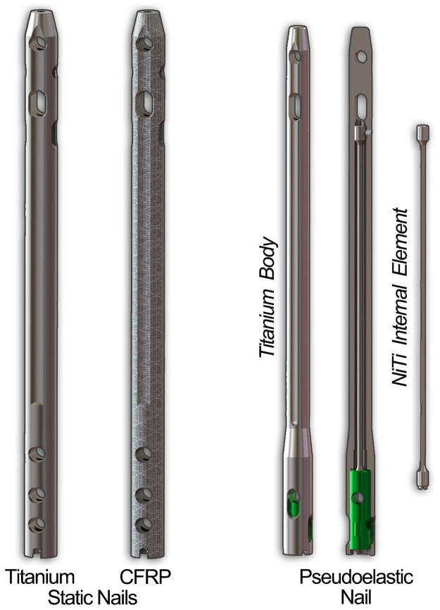
Two different IM nails were modeled for simulation in this study (Fig 1). First, a 10 mm diameter VersaNail® (Zimmer Biomet, Warsaw, IN, USA) was modeled to represent static IM nails made from both titanium and carbon-fiber reinforced polyetheretherketone (CFRP). While VersaNail is not currently manufactured in CFRP, this allowed us to create a direct comparison of the effect of material properties on performance. Next, a 10 mm diameter DynaNail® (MedShape-acquired by DJO Global, Atlanta, GA, USA) was modeled to represent a pseudoelastic NiTi nail. In contrast to IM nails that use external rods or internal screws to generate compression, the pseudoelastic NiTi nail uses an internal NiTi element that is stretched across the joints to be fused and partially released to generate compression [27].

Fig 1. Renderings of the three IM nails used in this study.

Fig 1

The static nails were modeled after a 10 mm VersaNail using both titanium and CFRP material properties, while the DynaNail represented a dynamic nail with an internal NiTi element inside a titanium outer body.

Patient-specific model generation

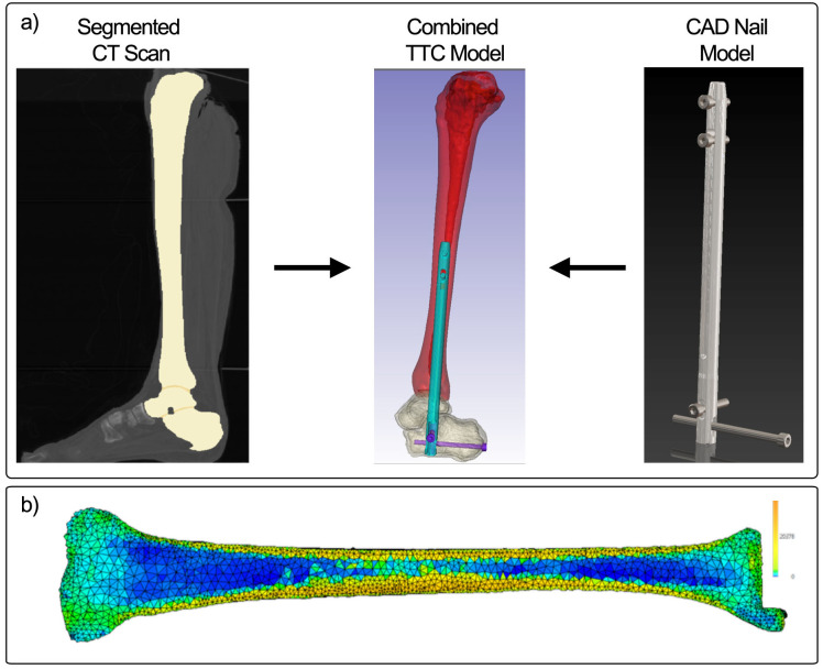
The right leg from a 55-year old, 82-kg male donor was obtained from Science Care, a non-transplant tissue bank accredited by the American Association of Tissue Banks. All Science Care donors are fully educated on the tissue and organ donation process, and signed consent is obtained in all cases. Because this study did not involve living human subjects, the Colorado Multiple Institutional Review Board (COMIRB) did not require committee approval of study protocols. A copy of the COMIRB decision tree for defining human subjects research is included in the S1 File. Quantitative computed tomography (QCT) images of the leg were taken and utilized to build a patient-specific finite element model (Fig 2). The specimen falls within the average age range for patients requiring hindfoot fusion (typically between 50 and 62 years) [28, 29]. Images were acquired using a Phillips Gemini 64 slice scanner (Phillips, Amsterdam, The Netherlands) at slice thickness of 0.67 mm and 120 kVp. Ankle joint positioning was maintained in neutral dorsiflexion-plantarflexion and neutral varus-valgus according to the suggested surgical techniques for IM fusion. Images were segmented into the individual bones and meshed for FEA using Simpleware ScanIP (Synopsys, Mountain View, CA, USA). Using a reference phantom (QCT Pro, Mindways, Austin, TX, USA), each voxel in the scan was converted to bone mineral density. Next, using the relationships described by Keyak et al., an elastic modulus for each voxel was defined [30]. The overall stiffness of the TTC bones was calculated in this study by applying compression across the nail and measuring the force required to reduce the TTC construct length by 1 mm.

Fig 2. Illustration of process for patient-specific finite element modeling.

Fig 2

A) Segmented CT images are combined with a CAD model of an IM nail to model an implanted device for TTC fusion. B) The densitometric properties of the bone are converted to modulus values to capture the distribution of properties in the bone allowing for the same patient-specific model to be applied in all 3 nailing systems.

The static IM nail was modeled after a 10 mm VersaNail using SolidWorks (Dassault Systems, Waltham, MA, USA), whereas the design files for the pseudoelastic nail were provided by the manufacturer. Material properties for the nail bodies were defined based on well-known material properties; for example, Ti6Al4V and CFRP were assigned modulus values of 110 GPa [31] and 13 GPa [3234], respectively, to match the materials used in commercially available nails. All fixation screws for the nails utilized the titanium material properties. Each nail was inserted into the model using the ScanIP (Simpleware) software. Nails were oriented to reflect the documentation that is available from the respective manufacturers. The internal NiTi element in the pseudoelastic nail was assigned material properties using the superelastic material model developed by Auricchio et al. and further refined by Anderson et al [31, 35]. Contact surfaces (coefficient of friction = 0.1) were defined between the outer nail body and surrounding bone and at the bone-bone contact regions in the ankle, and the outer surfaces of all screws were bonded with the surrounding bone tissue [36]. Frictionless contact was assigned to the sliding element in the pseudoelastic nail to allow it to slide freely within the nail body. Finally, models were meshed with linear tetrahedral elements and imported into ABAQUS (version 6.14, Simulia, Dassault Systems, Waltham, MA, USA). Mesh convergence and validation via comparison with experimental measurements of bone-IM nail construct stiffness were reported previously [31]. In brief, the mesh was refined until the computed stiffness of the TTC complex under uniaxial compression changed by less than 2%, and the final model consisted of a total of approximately 1.8 million tetrahedral elements. The resulting model had an axial stiffness within 5% of that for a cadaveric TTC complex previously measured by our research team (model stiffness = 2696 N/mm; cadaver stiffness = 2574 N/mm) [23].

Compression generation

Compression across the fusion interface was generated before analyzing the models for load-sharing or simulated resorption behavior. For the static titanium and CFRP nails, in clinical practice a set screw is used to achieve compression across the fusion site at the time of surgery. To apply a comparable level of compression in the models, uniaxial thermal contraction of the nail body in the axial direction was applied to reach 500 N of compression. To do so, a thermal coefficient of expansion was assigned to the material in the longitudinal direction of the nail, while the coefficients of expansion in the other two orthotropic directions (and to all other materials in the models) were set to zero. Temperature boundary conditions were then applied to cool the nails by 1°C, causing contraction in the longitudinal direction and generation of the desired 500-N force across the fusion site. Thermal expansion coefficients were adjusted so that the temperature decrease of 1°C shortened the length of the titanium and CFRP nails by 0.04 and 0.088%, respectively. The 500-N compression achieved by this method was comparable to the compression achieved in clinical applications of other IM nails [27]. Compression was applied to the pseudoelastic nail model following the methods described by Anderson et al [31]. In brief, the compressive element was initially stretched by 8 mm and then relaxed by 2 mm of displacement, after which it was locked in place to the nail body and sliding component within the nail yielding approximately 400 N of compression across the bones. 400 N of compression was the maximum amount of compression which could be applied due to the cross-sectional area of the NiTi element within the nail. This limitation is due to the nature of the pseudoelasticity of NiTi metal applying constant stress over a range of strains. After compression was applied, either gait loading or resorption of the bone was applied to each model to evaluate load-sharing and sustained compression, respectively. Additional details on the methodology used can be found in the S2 File.

Load-sharing analysis

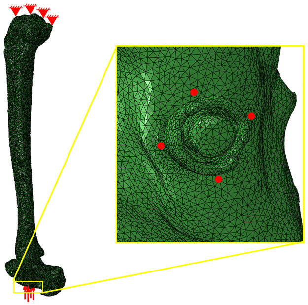
A peak compressive load of 1,121 N was applied to the modeled TTC-nail construct to evaluate load-sharing within the ankle-hindfoot to match maximum vertical ground reaction forces measured during walking. These measurements were provided by the Neuromuscular Physiology Lab at The Georgia Institute of Technology [31]. The load was divided among 4 nodes equally, 280.25 N per node, at the distal end of the calcaneus surrounding the opening where the IM nail was implanted (Fig 3). The applied load was also applied exclusively in the z-direction as it is the most substantial component of the gait load during walking. Nodes on the tibial plateau were held fixed. To analyze load-sharing, the model was sliced perpendicular to the axis of the nail at level of the distal tibial screw. Stress normal to the plane of the cut was integrated across each of the different components, and the resultant forces for the nail body, bone, and internal NiTi element (if applicable) were recorded. Load-sharing percentages were then calculated as the resultant force of the bone divided by the applied compressive load.

Fig 3. Boundary conditions applied for load sharing analysis.

Fig 3

Nodes on the proximal surface of the tibial plateau were pinned, and the total gait force was divided among four nodes (indicated by the four red dots in the yellow callout box) on the distal surface of the calcaneus surrounding the distal end of the IM nail.

Simulated resorption analysis

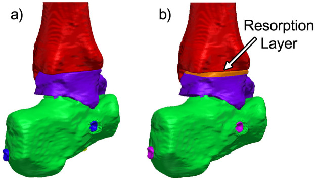
While it is recognized that bone resorption will occur across the fusion site, the exact amount of bone resorption that will occur in any patient is unknown. Pelton et al. reported at least 0.5 mm of resorption in 28 patients treated with the VersaNail [37]. Previous case studies using the DynaNail show radiographic evidence suggesting that several millimeters of resorption can occur [46, 14, 15]. Therefore, in this study, we systematically simulated a range of values to understand how the devices would behave with increasing amounts of resorption. Resorption was applied by a uniaxial thermal contraction of the resorption zone, using the methods described previously, in the superior-inferior direction (Fig 4). Approximately 0.5 mm of resorption was applied in all three models, and forces through the bone and nail were measured as a function of varying levels of resorption. The percentage of sustained compression was calculated by dividing the resultant compressive force in the bone after resorption by the initial compressive force applied to the model before resorption.

Fig 4. Load sharing and resorption models.

Fig 4

Model of the TTC complex used for load-sharing analysis. Each zone of different color represents a model component that can be assigned specific material properties and mechanical behavior. B) A 3.2 mm portion of the talus was designated to contract to simulate bone resorption.

Results and discussion

Load-sharing

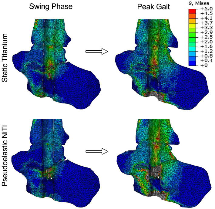
The first half of this study analyzed the load-sharing behavior of three different types of IM nails. Stress maps were produced for the unloaded state and at peak compressive load to illustrate how stress is distributed across the TTC complex under simulated walking conditions (Fig 5). In these images, the IM nail was hidden from the analysis such that the variation in stress in the bone is observed more clearly. For the static titanium nail, the initial compression of 500 N in the nail generates stress across the TTC complex. When focusing on the talus and distal portion of the tibia, typical stresses are within the range of 1 to 2.5 MPa. As peak loading is reached, there is an increase in stress throughout the joint, as indicated by a larger area of bone converting from blue (~0 to 1 MPa) to green (~1.5 to 3 MPa). In comparison, the pseudoelastic NiTi nail starts with a lower typical average stress across the talus and tibia. This is due to the initial compressive force value being lower than the static titanium nail (i.e., 400 N vs. 500 N). A similar response can be seen during peak loading, with an increase of stress distributed across the joints when loaded. Further, stresses below the subtalar joint and in the calcaneus at peak load were found to be higher in the pseudoelastic nail (≈ 2.3 MPa) compared to the titanium nail (≈ 0.8 MPa), indicating enhanced load-sharing with the bone.

Fig 5. Bone stresses under simulated gait loading.

Fig 5

Stress maps showing the distribution of stress within the ankle at swing phase and peak loading. In these images, the IM nail was subtracted from the analysis to show the stress changes in the bone only. The static CFRP nail is not shown due to its close similarity to the static titanium nail.

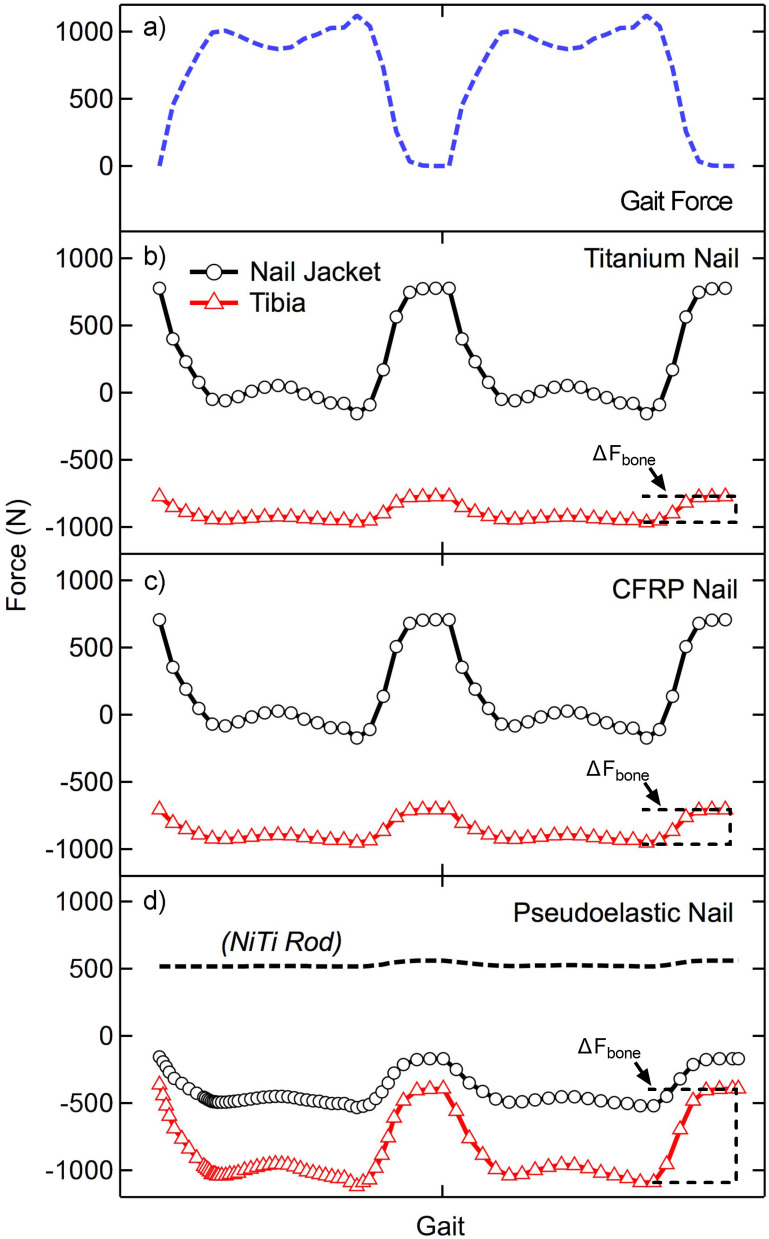
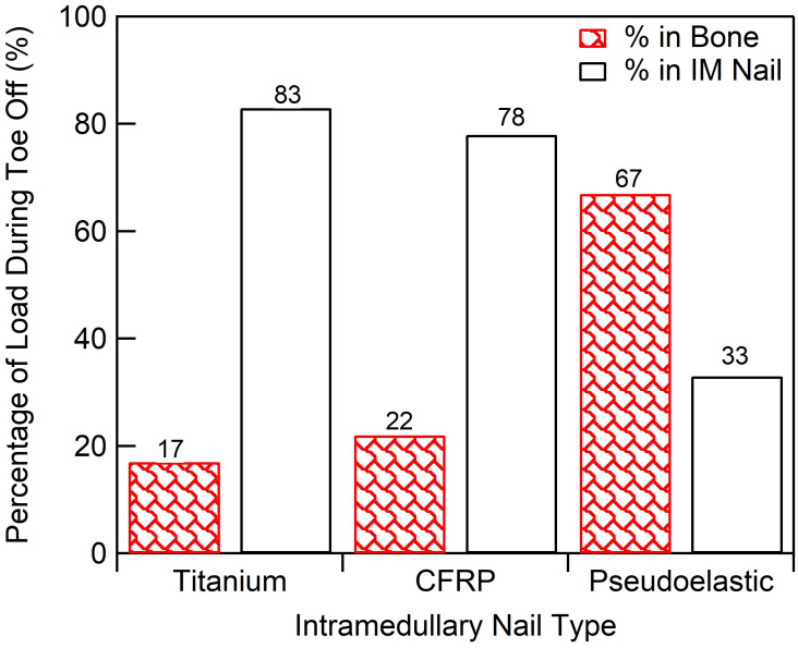
Two cycles of compressive loading, approximating the vertical component of the ground reaction force during gait, were applied quasistatically to each TTC model at discrete time points (44 for the static nails and 64 for the pseudoelastic nail), and the forces through the bone and nail body were recorded (Fig 6A). For each nail, the loading behavior was consistent between both cycles. Due to the different behavior of NiTi during lengthening and shortening, two cycles were simulated to account for any residual deformation remaining at the end of the first cycle. When analyzing load-sharing in the ankle and hindfoot, it is important to note that at the start of the gait cycle (i.e. swing phase). When the applied force is 0 N, the magnitude of forces within the bone and devices are equal to the initial value of applied compression; however, these forces are equal and opposite as the device is in tension (+) while the bone is under compression (-). Load-sharing analysis is primarily focused on how these forces change dynamically when an external load of 1,121 N is applied. The static titanium nail (Fig 6B) showed relatively little force variation through the bone (ΔFbone) with the majority of load being transferred through the nail jacket. The nail body experienced loads ranging from approximately 775 N to -150 N, indicating the nail was transitioning from a state of tension (applying compression to the bone segments) to a state of compression (shielding the bone segments from applied loads). The bone in this method experienced compressive loading ranging from -775 N to -960 N, an amplitude of 195 N (illustrating the load bypasses the arthrodesis bone segments through the fixation device). By comparison this is a much smaller load compared to the 925 N amplitude experienced by the nail body. At toe-off, (second peak in applied load shown in Fig 7), 83% of the total load was being transferred through the nail body rather than bone, demonstrating a large amount of stress shielding. Thus, the remaining 17% of the total load was shared to the bone. The static CFRP nail (Fig 6C) showed a similar response to the static titanium nail, with a near identical loading response. At toe-off, the nail body carried 78% of the total load, while the bone experienced 22% of the total load (ΔFbone), thus the nail shielded the bone from the majority of applied load. The pseudoelastic NiTi nail (Fig 6D) was the only nail type which demonstrated significant load transfer to the bone with loads through the tibia ranging from -365 N to -1040 N, a cyclic amplitude of 675 N. The nail jacket loads in this case ranged from -156 N to -490 N with a near constant load of 514 ± 44 N within the NiTi internal element. At toe-off, 33% of the load was transferred through the device with the remaining 67% applied to the bone (ΔFbone, Fig 7).

Fig 6. Applied forces and load sharing results.

Fig 6

A) Two cycles of applied loading used for this study. The change in force as a function of loading for the nail jacket and tibia is shown for (B) static titanium and (C) static CFRP nails. (D) The pseudoelastic nail has an extra component, the NiTi internal element, which is added to the analysis. The change in bone loading is highlighted with brackets for each device type and indicated with ΔFbone.

Fig 7. Load-sharing summary.

Fig 7

Load-sharing percentage of total compressive load transferred to bone for each IM nail.

Simulated resorption

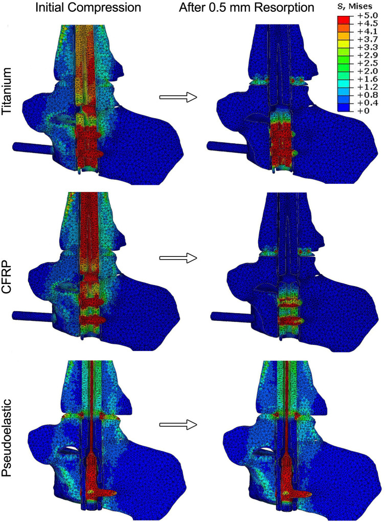
Simulated resorption was modeled for each condition to investigate how loss of bone at the joint surface would influence the compression across the fusion site. The resorption zone was limited to the talus, as represented in Fig 4B, and allowed for up to 0.5 mm of resorption. This was chosen to minimize modelling complexity as well as computational time. A sagittal view of the stress distributions across the ankle before and after resorption are shown in Fig 8. For the static titanium and CFRP nails, the stress maps reveal that the nail body is under stress to generate compression across the ankle. In comparison, the nail body in the pseudoelastic nail only experiences peak stresses of approximately 3 MPa; however, the internal NiTi element is responsible for compression generation and experiences well over 5 MPa. For all the nails analyzed, the initial conditions produced stress distributed throughout the joints, with peak values within the range of 2 to 3 MPa. These initial stress values were caused by initial compressions of 500 N for the static nails and 400 N for the pseudoelastic nail.

Fig 8. Results for simulated resorption.

Fig 8

Sagittal slices of the ankle show the stress distribution within the ankle, hindfoot, and device both before and after 0.5 mm simulated resorption. As stresses within the nail bodies and compressive element far exceed those of bone, a limit of 5 MPa was chosen for these maps to allow for adequate differentiation of stresses within the bone.

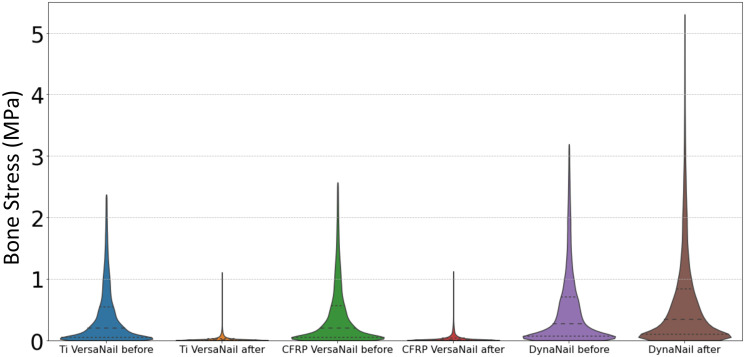
Simulated resorption values of 0.5 mm were applied to the static titanium, static CFRP, and pseudoelastic nails, respectively (Fig 8). For the static nails, most stress caused by initial compression disappears in the stress map with introduction of resorption, while two distinct regions of elevated stress remained. First, there was a localized region of stress at the proximal portion of the talus, which corresponds to the resorption zone highlighted in Fig 4. This stress results from the thermal contraction (i.e., simulated resorption) of these elements and should therefore be viewed as an artifact of the simulation methodology. This region of elevated thermal stress was limited to the region directly surrounding the nail body (i.e. the location of the view cut displayed in Fig 7), while the mean value for the whole resorption zone consisting of approximately 14,000 elements in each of the three models was negligible (mean = 0.009 MPa, standard deviation = 0.005 MPa). Second, there is a localized region of stress in between the two calcaneal screws in the titanium and CFRP nails. This is a result of the thermal contraction to the nail body designed to induce compression in our model. With the exception of these two localized regions, the stress within the nail and bone is essentially reduced to zero in the CFRP and titanium nails. For the pseudoelastic nail, the distribution of stress throughout the ankle and hindfoot is highly comparable to the initial compression conditions. The stress distributions of bone for each arthrodesis construct before and after bone resorption are provided as violin plots in Fig 9. The width of the plots represents the number of elements that experienced each level of stress, with the median and upper- and lower-quartiles indicated by dashed lines. As seen in these plots, simulated resorption in the static nail models produced a distinct downward shift of the bone stress distribution (i.e., a loss of compression), while simulated resorption in the pseudoelastic NiTi nail model actually produced a slight increase in bone stress. This upward shift in the pseudoelastic NiTi nail model can be attributed to small displacement of the sliding component in the superior direction as the NiTi shortened to maintain compression across the fusion site.

Fig 9. Bone stress distributions before and after simulated resorption.

Fig 9

Violin plots depict stress distributions in bone for each arthrodesis construct before and after 0.5 mm simulated resorption.

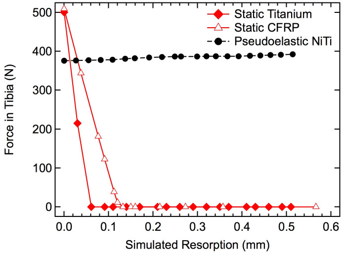
The resultant compression forces within the ankle and hindfoot were calculated to systematically investigate the influence of increasing resorption (Fig 10). For the static titanium and CFRP nails, initial compression was approximately 500 N, but the loads seen during resorption rapidly decreased linearly to 0 N after approximately 0.06 mm of resorption for the titanium nail and approximately 0.13 mm for the CFRP nail. The pseudoelastic nail, however, applied approximately 400 N of initial compression and maintained that loading across the entire resorption range. It should be noted that these models are utilizing an idealized material model for the bone and titanium, as such, the viscoelastic effects of natural bone are not captured.

Fig 10. Effects of simulated resorption on tibial force.

Fig 10

The compressive force transmitted through the tibial diaphysis is shown for the two static IM nails (red) and pseudoelastic IM nail (black) with increasing amounts of resorption.

Adequate sustained and cyclic compressive loading of bone segments provided by fixation hardware (i.e., IM nails) is essential to successful arthrodesis and bone health, but specifics of the loading environment within both hardware and fixed bones, and the way this environment varies with bony resorption changes over time, has previously remained undetermined. These data suggest a minimal degree of compression/load-sharing applied to bone segments in simulated TTC arthrodesis constructs using static compression devices. Specifically, the two static devices, independent of material stiffness, minimally load-shared with the bones, while the pseudoelastic nail had three times the compression/load-sharing capacity (ΔFbone) of the static nails. Furthermore, traditional static nails lost 100% of applied bone compression during simulated bone resorption, whereas the pseudoelastic nail maintained compression through all simulated resorption values (up to 0.5 mm).

Load-sharing data in this study suggests that traditional static nails made from titanium shield a majority of the load from the bone, with approximately 83% of the compressive load being transferred through the nail body, and only 17% being transferred through the bone. Because of this phenomenon, new nail designs have been created while utilizing lower modulus materials such as CFRP to reduce the overall stress shielding effect. However, this study illustrates that even a CFRP nail with ~10x decrease in modulus still stress-shielded approximately 78% of the load from the bone (a net 5% change in loading). This result is likely due to the high stiffness of the nail rather than the modulus of the material with which the nail is made. IM nails are a construct or structure rather than a material alone, and their mechanical structural properties (such as stiffness) depend on not only the material of which they are made, but also the amount and arrangement of that material (i.e., diameter of nail). For example, the axial stiffness for the titanium nail was approximately 52,000 N/mm while the CFRP nail had a stiffness of 8,200 N/mm, which were 19.3 and 3.0x the stiffness of the TTC bone complex in this study (2,696 N/mm). Resulting from the drastically greater stiffness of the nail in comparison to the TTC bone complex, the nails theoretically should carry proportionately greater load when compressed in parallel, a phenomenon illustrated by the data generated in this work.

In stark contrast, the compressive load applied through the tibia in the pseudoelastic NiTi nail construct was much greater at 67%, with only 33% through the device. This result is achieved by the device’s lower axial stiffness from the relatively compliant internal NiTi element (found to be 1,204 N/mm) combined with its already-dynamized screws, thus the enhanced load-sharing as this stiffness is closer to the stiffness of the TTC construct.

The resorption response analyzed in this study also demonstrated that the traditional titanium and newer CFRP nails are unable to provide any sustained compression over resorption ranges even far below those observed clinically [46, 14, 15]. The high stiffness of the nails prevents them from maintaining compression when resorption exceeds the elongation of the nail caused by the compressive force in the bone generated during nail insertion. Resulting from the non-uniform geometries and applied bending loads due to gait kinematics in the TTC joint, these data reveal that titanium and CFRP nails are not even capable of reaching their respective theoretical maximum resorption values of 0.4 mm and 0.5 mm [(initial compressive load * nail length)/(nail modulus * cross-sectional area)].

Again, in stark contrast to the static nail designs, these data illustrate the capability of the pseudoelastic nail with the NiTi compressive element to provide compression beyond 0.5 mm of bone resorption. The inherent pseudoelastic properties of NiTi allow for a nearly constant stress within the material as it transitions from the stretched and unstable martensite phase back to the unstretched and stable austenite phase in the crystal structure [38, 39]. This material phase transition behavior is leveraged by the pseudoelastic NiTi nail allowing it to provide sustained compression for 6 mm of contraction (approximately 6% strain), which is an order of magnitude higher than the strain stored in the static IM nails (approximately 0.4% strain) [27, 40]. This behavior enables the pseudoelastic nail device to apply continued intersegmental compression even when challenged with relatively large amounts of bone resorption.

Limitations of this study were that it primarily utilized linear-elastic material properties for the bone, whereas bone is viscoelastic in nature. The effect of this limitation is minimal however, as these viscoelastic effects are typically short lived and are trivial in the case of sustained compression over the course of resorption, which can occur over periods of weeks to months. The bone-implant interface in our models was also idealized. To create our models, each nail was digitally placed in the bone, and the corresponding volume of bone was deleted, producing a cavity in the bone that exactly matched the nail geometry. In clinical application, a reamer is used to create the cavity prior to inserting the nail, producing some surface irregularities that were not captured in our simulations. It should also be noted that the resorption models utilized in this study were limited to approximately 0.5 mm of resorption due to computational instability due to large deformations. However, as shown in the titanium and CFRP nails, compression is lost well within the ranges tested in this study. Another limitation is that the simulated gait loading used in this study did not include shifts in load location that occur during walking, and it only included the vertical force component, which dominates the ground reaction force magnitude. This loading scenario was intended to capture the overall magnitude and variation of the force transmitted through the fusion site, and it is possible that more complex simulations including shifts of load location and direction would reveal some more subtle shifts in stress levels and locations. Another limitation is that this study only utilized a single, patient-specific FEA model without cadaver testing validation of stress or strain values (only overall stiffness was compared, as noted in the methods section). While physical testing of multiple cadaver specimens can provide valuable information, this approach allowed comparisons between the performance of different IM nails in a single hindfoot model, eliminating the confounding factors of differing bone geometries and bone densities inherent to cadaveric testing. Additionally, this finite element analysis (FEA) technique enabled prediction of stresses throughout the entire bone and device construct, as opposed to point-wise measurements frequently produced during cadaveric testing. In order to fully confirm that the relative nail behaviors analyzed in this study are applicable across a wide range of skeletal anatomies, additional models would need to be developed based on subjects with variable size, age, sex, and bone quality. However, despite this limitation and the others discussed above, the results of this study provide the first steps toward a quantitative understanding of how dynamization and the use of a pseudoelastic IM nail can help provide favorable load sharing conditions and sustained compression in the face of local bone resorption at the ankle.

Conclusions

In conclusion, a patient-specific finite element model was developed to understand the load-sharing and resorption behavior in 3 different types of intramedullary nails for TTC fusion. It was found that, when digitally implanted into this individual’s anatomy, both the titanium and CFRP nails demonstrated poor load-sharing with the bone due to their relatively high stiffness, with approximately 17% and 22% of gait-generated load being transferred to the bone, respectively. The pseudoelastic NiTi nail was found to achieve increased load-sharing, with approximately 67% of the load being transferred through the bone. Additionally, the pseudoelastic NiTi nail maintained substantial compression over the full 0.5 mm of simulated bone resorption while the titanium and CFRP nails both lost all compression within 0.15 mm of resorption. The pseudoelastic NiTi nail modelled in this study represents a marked shift in the design and mechanical performance of IM nails, promoting both load-sharing and compression critical to a successful fusion.

Supporting information

S1 File. COMIRB decision tree.

This flow chart is used by the Colorado Multiple Institutional Review Board to determine whether a study falls under the classification of human subjects research. Because cadaveric specimens are not alive, the use of a donated specimen in our study did not qualify as human subjects research.

(PDF)

S2 File. Ankle fusion FE modeling SOP.

This standard operating procedure from our laboratory provides detailed instructions on how to run finite element analysis with an intramedullary nail digitally implanted in a patient-specific ankle model. Instructions on how to activate the nickel titanium compressive element in a pseudoelastic IM nail are included.

(PDF)

Acknowledgments

The authors would like to thank MedShape, Inc. (acquired by DJO/Enovis), for providing a pseudoelastic NiTi-based and titanium nail for modeling and Kurt “Burt” Jacobus for his enthusiastic support for the project. The authors thank Vasily Buharin for providing ground reaction force data for gait loading. Safranski and Dupont are paid employees of Enovis Foot & Ankle. Pacaccio is a paid consultant/advisor to Enovis Foot & Ankle.

Data Availability

All relevant data are within the paper and its Supporting information files.

Funding Statement

The author(s) received no specific funding for this work.

References

  • 1.Charnley J. COMPRESSION ARTHRODESIS OF THE ANKLE AND SHOULDER. J Bone Joint Surg. 1951;33B:180–191. [PubMed] [Google Scholar]
  • 2.Mückley T, Eichorn S, Hoffmeier K, et al. Biomechanical Evaluation of Primary Stiffness of Tibiotalocalcaneal Fusion with Intramedullary Nails. Foot & Ankle International. 2007;28:224–231. doi: 10.3113/FAI.2007.0224 [DOI] [PubMed] [Google Scholar]
  • 3.Jeng CL, Campbell JT, Tang EY, Cerrato RA, Myerson MS. Tibiotalocalcaneal Arthrodesis With Bulk Femoral Head Allograft for Salvage of Large Defects in the Ankle. Foot & Ankle International. 2013;34:1256–1266. doi: 10.1177/1071100713488765 [DOI] [PubMed] [Google Scholar]
  • 4.Ford S, Kwon J, Ellington J. Tibiotalocalcaneal Arthrodesis Utilizing a Titanium Intramedullary Nail With an Internal Pseudoelastic NiTiNOL Compression Element: A Retrospective Case Series of 33 Patients. J Foot Ankle Surg. 2019. doi: 10.1053/j.jfas.2018.08.046 [DOI] [PubMed] [Google Scholar]
  • 5.Hsu AR, Ellington JK, Adams SB. Tibiotalocalcaneal Arthrodesis Using a Nitinol Intramedullary Hindfoot Nail. Foot & Ankle Specialist. 2015;8:389–396. doi: 10.1177/1938640015598838 [DOI] [PubMed] [Google Scholar]
  • 6.Conklin MJ, Smith KE, Blair JW, Dupont KM. Total Ankle Replacement Conversion to Tibiotalocalcaneal Arthrodesis With Bulk Femoral Head Allograft and Pseudoelastic Intramedullary Nail Providing Sustained Joint Compression. Foot & Ankle Orthopaedics. 2018;3:2473011418804487. [DOI] [PMC free article] [PubMed] [Google Scholar]
  • 7.Bejarano-Pineda L, Sharma A, Adams SB, Parekh SG. Three-Dimensional Printed Cage in Patients With Tibiotalocalcaneal Arthrodesis Using a Retrograde Intramedullary Nail: Early Outcomes. Foot Ankle Spec. 2021;14:401–409. doi: 10.1177/1938640020920947 [DOI] [PubMed] [Google Scholar]
  • 8.Gilbert JA D L. E.; Atkinson M. A. The effect of external fixation stiffness on early healing of transverse osteotomies. J Orthop Res. 1989;7:389–397. doi: 10.1002/jor.1100070311 [DOI] [PubMed] [Google Scholar]
  • 9.Terjesen T A K.. The influence of different degrees of stiffness of fixation plates on experimental bone healing. J Orthop Res. 1988;6:293–299. doi: 10.1002/jor.1100060218 [DOI] [PubMed] [Google Scholar]
  • 10.Wu JJ S H. S.; Chao E. Y.; Kelly P. J. Comparison of osteotomy healing under external fixation devices with different stiffness characteristics. J Bone Joint Surg Am. 1984;66:1258–1264. [PubMed] [Google Scholar]
  • 11.Chamay A, Tschantz P. Mechanical influences in bone remodeling. Experimental research on Wolff’s law. Journal of Biomechanics. 1972;5:173–180. doi: 10.1016/0021-9290(72)90053-x [DOI] [PubMed] [Google Scholar]
  • 12.G AE, K J. The influence of induced micromovement upon the healing of experimental tibial fractures. The Journal of Bone and Joint Surgery. British volume. 1985;67-B:650–655. [DOI] [PubMed] [Google Scholar]
  • 13.Goodman S, Aspenberg P. Effects of mechanical stimulation on the differentiation of hard tissues. Biomaterials. 1993;14:563–569. doi: 10.1016/0142-9612(93)90171-w [DOI] [PubMed] [Google Scholar]
  • 14.Latt LD, Smith KE, Dupont KM. Revision Tibiotalocalcaneal Arthrodesis With a Pseudoelastic Intramedullary Nail:A Case Study. Foot & Ankle Specialist. 2017;10:75–81. [DOI] [PubMed] [Google Scholar]
  • 15.Kildow BJ G C. E.; Adams S. D.; Parekh S. G. Measurement of Nitinol Recovery Distance Using Pseudoelastic Intramedullary Nails for Tibiotalocalcaneal Arthrodesis. Foot & Ankle Specialist 2016. doi: 10.1177/1938640016656786 [DOI] [PubMed] [Google Scholar]
  • 16.Fragomen AT, Meyers KN, Davis N, Shu H, Wright T, Rozbruch SR. A Biomechanical Comparison of Micromotion after Ankle Fusion Using 2 Fixation Techniques: Intramedullary Arthrodesis Nail or Ilizarov External Fixator. Foot & Ankle International. 2008;29:334–341. doi: 10.3113/FAI.2008.0334 [DOI] [PubMed] [Google Scholar]
  • 17.Means KR, Parks BG, Nguyen A, Schon LC. Intramedullary Nail Fixation with Posterior-to-Anterior Compared to Transverse Distal Screw Placement for Tibiotalocalcaneal Arthrodesis: A Biomechanical Investigation. Foot & Ankle International. 2006;27:1137–1142. doi: 10.1177/107110070602701221 [DOI] [PubMed] [Google Scholar]
  • 18.Bennett GL, Cameron B, Njus G, Saunders M, Kay DB. Tibiotalocalcaneal Arthrodesis: A Biomechanical Assessment of Stability. Foot & Ankle International. 2005;26:530–536. doi: 10.1177/107110070502600706 [DOI] [PubMed] [Google Scholar]
  • 19.Lee AT, Sundberg EB, Lindsey DP, Harris AH, Chou LB. Biomechanical Comparison of Blade Plate and Intramedullary Nail Fixation for Tibiocalcaneal Arthrodesis. Foot & Ankle International. 2010;31:164–171. doi: 10.3113/FAI.2010.0164 [DOI] [PubMed] [Google Scholar]
  • 20.Mueckley TM, Eichorn S, Oldenburg Gv, et al. Biomechanical Evaluation of Primary Stiffness of Tibiotalar Arthrodesis with an Intramedullary Compression Nail and Four Other Fixation Devices. Foot & Ankle International. 2006;27:814–820. doi: 10.1177/107110070602701011 [DOI] [PubMed] [Google Scholar]
  • 21.Berson L, McGarvey WC, Clanton TO. Evaluation of Compression in Intramedullary Hindfoot Arthrodesis. Foot & Ankle International. 2002;23:992–995. doi: 10.1177/107110070202301103 [DOI] [PubMed] [Google Scholar]
  • 22.Eichhorn S L T.; M¸ckley T.; Trapp O.; Steinhauser E. The loss of compression in intramedullary ankle Arthrodesis using two different types of compression rods—A biomechanical study. Journal of Biomechanics. 2006;39:s136–s136. [Google Scholar]
  • 23.Yakacki CM, Khalil HF, Dixon SA, Gall K, Pacaccio DJ. Compression Forces of Internal and External Ankle Fixation Devices with Simulated Bone Resorption. Foot Ankle Int. 2010;31:76–85. doi: 10.3113/FAI.2010.0076 [DOI] [PubMed] [Google Scholar]
  • 24.Bevernage BD, Deleu PA, Maldague P, Leemrijse T. Technique and early experience with posterior arthroscopic tibiotalocalcaneal arthrodesis. Orthop Traumatol Surg Res. 2010;96:469–475. doi: 10.1016/j.otsr.2010.03.012 [DOI] [PubMed] [Google Scholar]
  • 25.Dupont KM, Shibuya N, Bariteau JT. Tibiotalocalcaneal Arthrodesis with Intramedullary Nails–Mechanobiological Background and Evolution of Compressive Technology. Glob J Ortho Res. 2019;1. [Google Scholar]
  • 26.Kreulen C, Lian E, Giza E. Technique for Use of Trabecular Metal Spacers in Tibiotalocalcaneal Arthrodesis With Large Bony Defects. Foot & Ankle International. 2017;38:96–106. doi: 10.1177/1071100716681743 [DOI] [PubMed] [Google Scholar]
  • 27.Yakacki CM, Gall K, Dirschl DR, Pacaccio DJ. Pseudoelastic intramedullary nailing for tibio–talo–calcaneal arthrodesis. Expert Review of Medical Devices. 2011;8:159–166. doi: 10.1586/erd.10.93 [DOI] [PubMed] [Google Scholar]
  • 28.Best MJ, Buller LT, Miranda A. National Trends in Foot and Ankle Arthrodesis: 17-Year Analysis of the National Survey of Ambulatory Surgery and National Hospital Discharge Survey. The Journal of Foot and Ankle Surgery. 2015;54:1037–1041. doi: 10.1053/j.jfas.2015.04.023 [DOI] [PubMed] [Google Scholar]
  • 29.Steele JR, Kildow BJ, Cunningham DJ, et al. Comparison of Tibiotalocalcaneal Arthrodeses Using a Sustained Dynamic Compression Nail Versus Nondynamized Nails. Foot & Ankle Specialist. 2020;13:193–200. doi: 10.1177/1938640019843332 [DOI] [PubMed] [Google Scholar]
  • 30.Keyak JH L I. Y.; Skinner H.B. Correlations between orthogonal mechanical properties and density of trabecular bone: Use of different densitometric measures. J Biomed Mater Res. 1994;28:1329–1336. doi: 10.1002/jbm.820281111 [DOI] [PubMed] [Google Scholar]
  • 31.Anderson RT, Pacaccio DJ, Yakacki CM, Carpenter RD. Finite element analysis of a pseudoelastic compression-generating intramedullary ankle arthrodesis nail. Journal of the Mechanical Behavior of Biomedical Materials. 2016;62:83–92. doi: 10.1016/j.jmbbm.2016.04.037 [DOI] [PubMed] [Google Scholar]
  • 32.Fitch DA, Hoffmeister BK, de Ana J. Ultrasonic evaluation of polyether ether ketone and carbon fiber-reinforced PEEK. Journal of Materials Science. 2010;45:3768–3777. [Google Scholar]
  • 33.Qin W L Y.; Ma J.; Liang Q.; Tang B. Mechanical properties and cytotoxicity of hierarchical carbon fiber-reinforced poly (ether-ether-ketone) composites used as implant materials. Journal of the Mechanical Behavior of Biomedical Materials. 2019;89:227–233. doi: 10.1016/j.jmbbm.2018.09.040 [DOI] [PubMed] [Google Scholar]
  • 34.Chang B G J.; Long Z.; Li Z.; Ruan S.; Shen C. Effects of temperature and fiber orientation on the tensile behavior of short carbon fiber reinforced PEEK composites. Polymer Composities. 2020;42:597–607. [Google Scholar]
  • 35.Auricchio F, Taylor RL, Lubliner J. Shape-memory alloys: macromodelling and numerical simulations of the superelastic behavior. Computer Methods in Applied Mechanics and Engineering. 1997;146:281–312. [Google Scholar]
  • 36.Yu HY, Cai ZB, Zhou ZR, Zhu MH. Fretting behavior of cortical bone against titanium and its alloy. Wear 2005;259:910–918. [Google Scholar]
  • 37.Pelton K, Hofer JK, Thordarson DB. Tibiotalocalcaneal Arthrodesis Using a Dynamically Locked Retrograde Intramedullary Nail. Foot & Ankle International. 2006;27:759–763. doi: 10.1177/107110070602701001 [DOI] [PubMed] [Google Scholar]
  • 38.Frick CP, Ortega AM, Tyber J, Gall K, Maier HJ. Multiscale structure and properties of cast and deformation processed polycrystalline NiTi shape-memory alloys. Metallurgical and Materials Transactions A. 2004;35:2013–2025. [Google Scholar]
  • 39.Frick CP, Ortega AM, Tyber J, et al. Thermal processing of polycrystalline NiTi shape memory alloys. Materials Science and Engineering: A. 2005;405:34–49. [Google Scholar]
  • 40.Safranski D, Dupont K, Gall K. Pseudoelastic Nitinol in Orthopaedic Applications. Shape Memory and Superelasticity. 2020;6:332–341. [Google Scholar]

Decision Letter 0

Pawel Klosowski

20 Mar 2023

PONE-D-23-03456Effect of Intramedullary Nail Stiffness on Load-sharing in Tibiotalocalcaneal Arthrodesis: A Patient-Specific Finite Element StudyPLOS ONE

Dear Dr. Carpenter,

Thank you for submitting your manuscript to PLOS ONE. After careful consideration, we feel that it has merit but does not fully meet PLOS ONE’s publication criteria as it currently stands. Therefore, we invite you to submit a revised version of the manuscript that addresses the points raised during the review process.

Please submit your revised manuscript by May 04 2023 11:59PM. If you will need more time than this to complete your revisions, please reply to this message or contact the journal office at plosone@plos.org. When you're ready to submit your revision, log on to https://www.editorialmanager.com/pone/ and select the 'Submissions Needing Revision' folder to locate your manuscript file.

Please include the following items when submitting your revised manuscript:

  • A rebuttal letter that responds to each point raised by the academic editor and reviewer(s). You should upload this letter as a separate file labeled 'Response to Reviewers'.

  • A marked-up copy of your manuscript that highlights changes made to the original version. You should upload this as a separate file labeled 'Revised Manuscript with Track Changes'.

  • An unmarked version of your revised paper without tracked changes. You should upload this as a separate file labeled 'Manuscript'.

If you would like to make changes to your financial disclosure, please include your updated statement in your cover letter. Guidelines for resubmitting your figure files are available below the reviewer comments at the end of this letter.

If applicable, we recommend that you deposit your laboratory protocols in protocols.io to enhance the reproducibility of your results. Protocols.io assigns your protocol its own identifier (DOI) so that it can be cited independently in the future. For instructions see: https://journals.plos.org/plosone/s/submission-guidelines#loc-laboratory-protocols. Additionally, PLOS ONE offers an option for publishing peer-reviewed Lab Protocol articles, which describe protocols hosted on protocols.io. Read more information on sharing protocols at https://plos.org/protocols?utm_medium=editorial-email&utm_source=authorletters&utm_campaign=protocols.

We look forward to receiving your revised manuscript.

Kind regards,

Pawel Klosowski, D.Sc.

Academic Editor

PLOS ONE

Journal Requirements:

When submitting your revision, we need you to address these additional requirements.

1. Please ensure that your manuscript meets PLOS ONE's style requirements, including those for file naming. The PLOS ONE style templates can be found at 

https://journals.plos.org/plosone/s/file?id=wjVg/PLOSOne_formatting_sample_main_body.pdf and 

https://journals.plos.org/plosone/s/file?id=ba62/PLOSOne_formatting_sample_title_authors_affiliations.pdf

2.  Thank you for stating the following in the Competing Interests section: 

"I have read the journal's policy and the authors of this manuscript have the following competing interests: Safranski and Dupont are paid employees of Enovis Foot & Ankle. Pacaccio is a paid consultant/advisor to Enovis Foot & Ankle. Safranski reports stock ownership and other compensation from MedShape-acquired by DJO during the conduct of this study and outside the submitted work. Dupont reports stock ownership and other compensation from MedShape-acquired by DJO during the conduct of this study and outside the submitted work."

Please confirm that this does not alter your adherence to all PLOS ONE policies on sharing data and materials, by including the following statement: "This does not alter our adherence to  PLOS ONE policies on sharing data and materials.” (as detailed online in our guide for authors http://journals.plos.org/plosone/s/competing-interests).  If there are restrictions on sharing of data and/or materials, please state these. Please note that we cannot proceed with consideration of your article until this information has been declared. 

Please include your updated Competing Interests statement in your cover letter; we will change the online submission form on your behalf.

3. Please include captions for your Supporting Information files at the end of your manuscript, and update any in-text citations to match accordingly. Please see our Supporting Information guidelines for more information: http://journals.plos.org/plosone/s/supporting-information. 

Additional Editor Comments:

According to reviewers opinion the paper needs major revision. The details you can read in the opinions. You can submit the corrected version within 45 days.

[Note: HTML markup is below. Please do not edit.]

Reviewers' comments:

Reviewer's Responses to Questions

Comments to the Author

1. Is the manuscript technically sound, and do the data support the conclusions?

The manuscript must describe a technically sound piece of scientific research with data that supports the conclusions. Experiments must have been conducted rigorously, with appropriate controls, replication, and sample sizes. The conclusions must be drawn appropriately based on the data presented.

Reviewer #1: Partly

Reviewer #2: Partly

**********

2. Has the statistical analysis been performed appropriately and rigorously?

Reviewer #1: N/A

Reviewer #2: N/A

**********

3. Have the authors made all data underlying the findings in their manuscript fully available?

The PLOS Data policy requires authors to make all data underlying the findings described in their manuscript fully available without restriction, with rare exception (please refer to the Data Availability Statement in the manuscript PDF file). The data should be provided as part of the manuscript or its supporting information, or deposited to a public repository. For example, in addition to summary statistics, the data points behind means, medians and variance measures should be available. If there are restrictions on publicly sharing data—e.g. participant privacy or use of data from a third party—those must be specified.

Reviewer #1: No

Reviewer #2: Yes

**********

4. Is the manuscript presented in an intelligible fashion and written in standard English?

PLOS ONE does not copyedit accepted manuscripts, so the language in submitted articles must be clear, correct, and unambiguous. Any typographical or grammatical errors should be corrected at revision, so please note any specific errors here.

Reviewer #1: Yes

Reviewer #2: Yes

**********

5. Review Comments to the Author

Please use the space provided to explain your answers to the questions above. You may also include additional comments for the author, including concerns about dual publication, research ethics, or publication ethics. (Please upload your review as an attachment if it exceeds 20,000 characters)

Reviewer #1: Dear authors,

I have found this article very interesting, well-written, and well-structured.

I am sending you the following major issues that, by my understanding, should be considered:

1. Regarding the FE models, the information is insufficient for reproducibility (unless the source ABAQUS files are supplied along with the publication).

2. The description of the FEM boundary conditions should be explained in more detail in the article, as in the text and graphically.

4. It is said that the mesh convergence and validation were reported in [31], but this reference does not explicitly show the validation but only comments on it. Could you please extend the explanation?

3. Please explain why linear tetrahedral elements have been used instead of higher-order ones. Also, reference [31] does not specify which element order was used and shows some artificial bending due to using tetrahedral finite elements. Could parabolic elements or finer meshes have fixed the problem? Is this problem also present in the current simulations?

4. The thermal contraction of the resorption zone introduces fictitious (tensile) stresses. How can you analyze the load-sharing behavior when fictitious stresses are involved? Please quantify such stresses and explain why they are neglectable or do not affect the calculation of the resultant forces.

5. Given that the equivalent von Mises stress is signless and more related to shear than normal stresses, why is it the only stress used? Maximum/minimum normal stresses or principal stresses arrow maps would be much more helpful in understanding the system’s mechanics and appropriate for analyzing the stresses in the bone. Moreover, these other stresses allow for distinguishing between tensile and compressive stresses, while von Mises hides this aspect. Also, it can help to quantify and understand the magnitude of the fictitious resorption stresses.

On the other hand, the following minor issues can be considered:

6. A reference for the friction coefficient value of 0.1 between the nail body and the surrounding bone would be necessary.

7. Which friction coefficient value is used for the contact between the nail and the nail body?

8. Why “stress heat map” instead of simply “stress map”?

Sincerely

Reviewer #2: PONE-D-23-03456

Effect of Intramedullary Nail Stiffness on Load-sharing in Tibiotalocalcaneal Arthrodesis: A Patient-Specific Finite Element Study

Terrill et al.

Comments to Authors:

In this manuscript, the authors built a finite element hindfoot model to determine the influence of different intramedullary nails used for tibiotalocalcaneal arthrodesis on the amount of bone load-sharing with and without different bone resorption depths. Overall, the manuscript is well written, but there are some concerns related to the boundary conditions of the model and its ability to appropriately investigate the devices of interest.

Introduction

Lines 48-50, Page 3: A clear and concise explanation of “dynamization of the arthrodesis construct’ should be included prior to or within this sentence to help explain this concept before moving on.

Lines 52-57, Page 3: You state that important factors are maximizing bone-to-bone contact across the fusion site and minimizing micromotion of the joint for proper fusion. You also mention that the device should be rigid to prevent excessive bending and torsional moments at the TTC complex.

How does bone-to-bone contact changes with these different devices?

How does the micromotion change?

Lines 64-66, Page 4: The language should change here to emphasize the comparison of different IM nails here because some of the authors of this manuscript have previously published at least one other study quantifying the load-sharing of arthrodesis devices and bone at the fusion sit, as I understand it.

Lines 78-80, Page 4: For (1), be more specific. The authors are not testing a hypothesis for any material implemented. They are testing a hypothesis for two specific materials. Define ‘high stiffness’. Why not just stick to the second part of the hypothesis? The introduction leads into the second part of the hypothesis, but the first part seems out of place or at least not supported in the Introduction.

Method

Lines 99-100, Page 5: The study is interesting, but the single, healthy subject used to develop the finite element model without experimental validation limits the impact.

Lines 112-113, Page 5: Why not demonstrate the influence of different IM nails with varying material properties, since only one subject was used to develop a single finite element model? In the previous study by the authors, they vary the effect of bone modulus and demonstrate changes. How does the comparison in this manuscript of the different IM nails changes in relation to the bone modulus, and does the positive effect of the dynamization decrease with different bone quality?

Lines 129-130, Page 6: Why not demonstrate the influence from different IM nails with different alignment? How sensitive are the results to changes in position and alignment of the device?

Lines 132-135, Pages 6-7: Where does the coefficient of friction value come from?

Lines 132-135, Pages 6-7: Is the bone-nail interface perfect? Is that realistic? What implications are there for modeling the IM nails this way? This model representation negates the ability of the device to settle with further loading and potentially change the results. This should probably be mentioned in the Discussion.

Lines 135-136, Page 7: Do you mean frictionless here? The language used in this sentence does not make this clear.

Lines 142-143, Page 7: I would refer to this as ‘simulated resorption behavior’ because the representation of resorption is simplified.

Lines 164-166, Page 8: I am confused by the loading applied. How can you apply this load to just the distal end of the calcaneus where the IM nail was implanted and call it ‘gait loading’? What about during toe-off when the ground reaction force is being applied to the forefoot, which wasn’t modeled? Also, why weren’t the off axis loads applied to assess the complexity of loads during stance? The loading does not seem physiologic if all the load is always applied to the distal calcaneus near the IM nail implanted.

Results

Lines 197-198, Page 9: Change ‘no gait loading’ and ‘peak gait load’ to ‘unloaded’ and ‘peak compressive load’. This manuscript may be basing the compressive force off of the ground reaction forces during gait, but they are only being applied as a range of axial compressive loads. They do not replicate the loads under walking conditions, as these would be more complex.

Lines 201-210, Page 10: Why focus on reporting absolute values? Since you only have one subject without any experimental validation, the analysis should consist of relative comparisons between the different nails. There is no ability to determine if these values are correct, or that they represent the values that would be demonstrated in others.

Lines 205-206, Page 10: Why did you compare 400 to 500N? If you can’t achieve 500N with the NiTi nail, then why not just compare each to 400N? I understand that the differences found between the two are vast, even with this discrepancy, but the inconsistency in methodology doesn’t make sense.

Lines 217-224, Pages 10-11: The simulations seem to be quasistatic and not dynamic, so I’m not sure why two cycles of gait loading were performed. It seems like the axial load was just varied. Were dynamic simulations performed and acceleration of loading during walking included?

Lines 232-234, Page 11: It is not clear where at ‘toe-off’ you are referring to make this calculation.

Lines 253-264, Page 12: I like the sensitivity analysis of simulated bone resorption in this study. Why not just focus on this aspect? Since this is one model of a single foot without experimental validation, the sensitivity of different amounts of bone resorption is more interesting and impactful than the earlier analysis.

Discussion

Lines 310-313, Page 14: Can you really say that this is dynamic compressive loading? It is not clear from the methods that you can. It appears you applied different values of compressive load near the site of the nail.

Lines 313-315, Page 14: I would use ‘suggest’ instead of ‘exhibit’ here. The language is a little strong for an analysis with one model.

Lines 369-372, Page 17: Why not include more specimens then to present results in light of different subject variability in bone material properties, geometry, alignment, etc.?

Lines 372-374, Page 17: This is true, but the finite element model would be more impactful with some level of experimental validation and then use this to even extrapolate predictions of stress.

**********

6. PLOS authors have the option to publish the peer review history of their article (what does this mean?). If published, this will include your full peer review and any attached files.

If you choose “no”, your identity will remain anonymous but your review may still be made public.

Do you want your identity to be public for this peer review? For information about this choice, including consent withdrawal, please see our Privacy Policy.

Reviewer #1: No

Reviewer #2: No

**********

[NOTE: If reviewer comments were submitted as an attachment file, they will be attached to this email and accessible via the submission site. Please log into your account, locate the manuscript record, and check for the action link "View Attachments". If this link does not appear, there are no attachment files.]

While revising your submission, please upload your figure files to the Preflight Analysis and Conversion Engine (PACE) digital diagnostic tool, https://pacev2.apexcovantage.com/. PACE helps ensure that figures meet PLOS requirements. To use PACE, you must first register as a user. Registration is free. Then, login and navigate to the UPLOAD tab, where you will find detailed instructions on how to use the tool. If you encounter any issues or have any questions when using PACE, please email PLOS at figures@plos.org. Please note that Supporting Information files do not need this step.

Attachment

Submitted filename: 2023-0313_PONE-D-23-03456 Review_blind.docx

PLoS One. 2023 Nov 16;18(11):e0288049. doi: 10.1371/journal.pone.0288049.r002

Author response to Decision Letter 0


26 Apr 2023

Response to Reviewers

The authors would like to thank the reviewers for their efforts in thoughtfully evaluating our manuscript. Below we have included each question/comment provided by the reviewers along with our responses. The Revised Manuscript with Track Changes document highlights the changes made in response to the critiques, and the changes are described below. Please note that the line numbers listed in the comments below correspond to the line numbers in the marked up copy. We feel that these changes have resulted in a stronger paper that is now suitable for publication in PLOS ONE.

Reviewer #1:

1. Regarding the FE models, the information is insufficient for reproducibility (unless the source ABAQUS files are supplied along with the publication).

The text in the methods section has been edited to include more details about the model, and a new figure (Fig 3) was added to more clearly explain how boundary conditions were applied. In addition, we now include in the supporting information (S2 File. Ankle fusion FE modeling SOP) our lab’s standard operating procedure document with detailed instructions on how to run simulations of the pseudoelastic IM nail in Abaqus. Because this document alone spans 18 pages, our description in the materials and methods section is abbreviated out of necessity. The additional information added to the manuscript and supporting information provides the details needed for reproducibility.

2. The description of the FEM boundary conditions should be explained in more detail in the article, as in the text and graphically.

A new Fig 3 was added to the manuscript to more clearly present the pinned boundary condition at the proximal surface of the tibia and the four force vector locations on the distal surface of the calcaneus.

4. It is said that the mesh convergence and validation were reported in [31], but this reference does not explicitly show the validation but only comments on it. Could you please extend the explanation?

Additional information about mesh convergence (refined until total model stiffness varied by less than 5%) and validation (stiffness of model compared with that of experimental stiffness measurements) has been added to page (lines 149-154).

3. Please explain why linear tetrahedral elements have been used instead of higher-order ones. Also, reference [31] does not specify which element order was used and shows some artificial bending due to using tetrahedral finite elements. Could parabolic elements or finer meshes have fixed the problem? Is this problem also present in the current simulations?

Linear elements were used to help with computational efficiency. The final mesh for the pseudoelastic nail contained 1.8 million elements and accounted for the complex, nonlinear material behavior of nickel titanium. This model pushed the limits of our laboratory’s computational resources, and adding the additional degrees of freedom offered by quadratic elements was deemed unnecessary. The relatively simpler static nail models could use quadratic elements and still be solved in a reasonable amount of time in our lab, but we thought it was more important to maintain a consistent element type in all three models. The gradient in stress noted in reference 31 from 2016 (attributed to a slight bending component produced by the NiTi wire) is now understood to be due to the combination of screw placement and the inherent asymmetry in placement of pin boundary conditions on the tibial plateau, neither of which are expected to be significantly affected by element type.

4. The thermal contraction of the resorption zone introduces fictitious (tensile) stresses. How can you analyze the load-sharing behavior when fictitious stresses are involved? Please quantify such stresses and explain why they are neglectable or do not affect the calculation of the resultant forces.

The thermal contraction used to simulate bone resorption in our model indeed results in stresses in the resorption zone. Load sharing results under simulated resorption conditions were evaluated in the tibial diaphysis, proximal to the resorption region. Because the distal end of the model is free to move, the stresses in the resorption zone lead to contraction across the fusion site and a drastic reduction in force passing through the tibia for the static nails, as shown in Fig. 10 (Fig. 9 in the original manuscript). The thermal stresses that remain (mean value =0.009 MPa +/- standard deviation of 0.005) in the 14,055 elements of the resorption region) are essentially the same for all three nail models and are negligible compared with the stresses in other locations. We have edited the text describing the resorption results (lines 306-310) to make this clearer.

5. Given that the equivalent von Mises stress is signless and more related to shear than normal stresses, why is it the only stress used? Maximum/minimum normal stresses or principal stresses arrow maps would be much more helpful in understanding the system’s mechanics and appropriate for analyzing the stresses in the bone. Moreover, these other stresses allow for distinguishing between tensile and compressive stresses, while von Mises hides this aspect. Also, it can help to quantify and understand the magnitude of the fictitious resorption stresses.

The reviewer is correct that the use of von Mises stress precludes the ability to differentiate between zones of tensile and compressive stress. We chose to focus on von Mises stress, because it is one way of summarizing the entire stress state at each point with a single value indicating the level of distortional stress. Due to the compressive loads created by the IM nails and the simulated ground reaction forces, stresses in our models are by far dominated by compression (other than the tensile stress in the nickel titanium component of the pseudoelastic nail). There are no areas of notable tensile stress, other than the thermal stresses in the resorption region which, as noted in the previous comment, are negligible compared with stresses in the bones and nails.

6. A reference for the friction coefficient value of 0.1 between the nail body and the surrounding bone would be necessary.

The following literature source is now cited: Yu HY, Cai ZB, Zhou ZR, Zhu MH. Fretting behavior of cortical bone against titanium and its alloy. Wear 2005;259:910-918. This study found the friction coefficients in the range of 0.17-0.29 for small displacements between titanium and cortical bone. During model development, we tested coefficients ranging from 0 (frictionless) to 0.4 and found no noticeable difference in the resulting stress distribution.

7. Which friction coefficient value is used for the contact between the nail and the nail body?

All metal components (screws and nail bodies) were treated as bonded (nodes shared at the interface), except for the interface between the sliding element and body in the pseudoelastic nail, which was modeled as frictionless contact.

8. Why “stress heat map” instead of simply “stress map”?

This was simply a style choice of the authors. We have removed “heat” from all mentions of the stress maps in the paper.

Reviewer #2:

Introduction

Lines 48-50, Page 3: A clear and concise explanation of “dynamization of the arthrodesis construct’ should be included prior to or within this sentence to help explain this concept before moving on.

A brief statement describing dynamization has been added to this paragraph.

Lines 52-57, Page 3: You state that important factors are maximizing bone-to-bone contact across the fusion site and minimizing micromotion of the joint for proper fusion. You also mention that the device should be rigid to prevent excessive bending and torsional moments at the TTC complex. How does bone-to-bone contact changes with these different devices? How does the micromotion change?

Bone-to-bone contact is identical in all three of our models, because the same bony geometry was used for each. We did not explicitly measure micromotion. The models provide a huge amount of data on different mechanical quantities, including stress and strain (individual stress/strain components, principal stresses/strains, pressure, deviatoric stress, and other summary values like von Mises stress, octahedral shear stress, strain energy density, etc.), displacements, and reaction forces, among others. In order to keep our analysis focused and succinct, we chose to focus on stress (von Mises stress specifically) and load sharing, as we feel these two quantities best summarize the mechanical aspects we aim to understand (load sharing between the devices and bone and influence of bone resorption on stress generated across the fusion site).

Lines 64-66, Page 4: The language should change here to emphasize the comparison of different IM nails here because some of the authors of this manuscript have previously published at least one other study quantifying the load-sharing of arthrodesis devices and bone at the fusion site, as I understand it.

We have revised this sentence to state, “…however, to the best of the authors’ knowledge, no studies have attempted to quantify how different IM nail designs and materials affect load-sharing between the arthrodesis device and native bone across the fusion site.”

Lines 78-80, Page 4: For (1), be more specific. The authors are not testing a hypothesis for any material implemented. They are testing a hypothesis for two specific materials. Define ‘high stiffness’. Why not just stick to the second part of the hypothesis? The introduction leads into the second part of the hypothesis, but the first part seems out of place or at least not supported in the Introduction.

Thank you for this suggestion. We revised our hypothesis statement to read, “We hypothesized that dynamization would allow for 1) improved load-sharing and 2) sustained intersegmental compression in the presence of localized bone resorption at the fusion site.” The new statement provides more specific information and more accurately reflects the purpose of the study.

Methods

Lines 99-100, Page 5: The study is interesting, but the single, healthy subject used to develop the finite element model without experimental validation limits the impact.

We have added more information on experimental validation (see Methods section, lines 149-154), in which we compared the FE model compressive stiffness to that of a bone-IM nail construct measured experimentally. The reviewer may also wish to see reference 31 for additional details. As for the use of a single subject, we view this aspect as a strength of the study. It would be impossible to accurately experimentally measure the effects of three different IM nails in the exact same TTC specimen, due to the damage caused by implantation and removal of multiple devices. Our methodology allows us to isolate the effects of the IM nails without additional variability introduced by using multiple TTC complex specimens.

Lines 112-113, Page 5: Why not demonstrate the influence of different IM nails with varying material properties, since only one subject was used to develop a single finite element model? In the previous study by the authors, they vary the effect of bone modulus and demonstrate changes. How does the comparison in this manuscript of the different IM nails changes in relation to the bone modulus, and does the positive effect of the dynamization decrease with different bone quality?

These are all good and thoughtful questions, and the authors appreciate your suggestion. Our previous study, which established the pseudoelastic nail model, did quantify the effects of bone quality (in terms of Young’s modulus) on load sharing, and we found that decreasing bone density (and therefore bone modulus) led to a shift in loading from the bone to the nail. Based on those results, we know that the same effect would occur in the other nails analyzed in the current study. As for the effects of bone quality on the effectiveness of dynamization, because the NiTi element is activated and locked into place on the right side of the unloading plateau (see ref. 31 for diagram), there is an additional 3% strain that can be compensated for by contraction of the NiTi element. This is a relatively large amount of “slack” in the system that can be accommodated, and therefore we do not have reason to believe that a change in bone modulus would affect the maintenance of compression in any significant way. While we could analyze an additional set of models with varying bone properties, we feel that it would not fit within the focus of the current study, which aims to understand the effects of nail material properties (the titanium and carbon fiber nails are identical, other than material properties) and dynamization on load sharing and maintenance of compression in the face of localized bone resorption. Additionally, given the reviewer’s suggestion that we should only focus on one aspect (accommodation of resorption), we feel that adding additional models would be contrary to this critique while taking away from the focus of our study.

Lines 129-130, Page 6: Why not demonstrate the influence from different IM nails with different alignment? How sensitive are the results to changes in position and alignment of the device?

All three nails were aligned identically in the TTC complex, as verified by our clinical author (Pacaccio). Fig 5 provides a good visual reference of identical alignment. A parameter study on spatial placement and alignment of the nails would be valuable, but in this study we wanted to focus on comparing the different nail designs and materials. Also, as noted in the comment above, we received a critique stating that we may already be focusing on too many issues.

Lines 132-135, Pages 6-7: Where does the coefficient of friction value come from?

The following literature source is now cited: Yu HY, Cai ZB, Zhou ZR, Zhu MH. Fretting behavior of cortical bone against titanium and its alloy. Wear 2005;259:910-918.

Lines 132-135, Pages 6-7: Is the bone-nail interface perfect? Is that realistic? What implications are there for modeling the IM nails this way? This model representation negates the ability of the device to settle with further loading and potentially change the results. This should probably be mentioned in the Discussion.

The bone-nail interface is “perfect,” because we place the nail in the bone and “overwrite” the bone tissue occupying the same space, producing a space in the bone that is the exact shape of the implant. In a real surgery, a reamer is used to produce a cavity for fitting the nail into place, so the reviewer is correct that the perfect interface is most likely not 100% realistic. However, we do not expect the smooth surface geometry of the interface to have any significant impact on our results. Because we applied contact conditions between the nail and bone, relative motion can occur at the interface, and this should be a reasonable approximation of what happens in a real patient. We have added statements to the discussion to address this issue (lines 397-402). On a closely-related note, we mention at the end of the results section (lines 335-336) and in the limitations portion of the discussion (lines 394-397) that the viscoelastic behavior of bone, which would lead to additional settling, was also not simulated in our models.

Lines 135-136, Page 7: Do you mean frictionless here? The language used in this sentence does not make this clear.

Thank you for pointing out this misstatement. We revised the text to state that frictionless contact was used in this location.

Lines 142-143, Page 7: I would refer to this as ‘simulated resorption behavior’ because the representation of resorption is simplified.

Thank you for this suggestion. We have made the requested change in the text.

Lines 164-166, Page 8: I am confused by the loading applied. How can you apply this load to just the distal end of the calcaneus where the IM nail was implanted and call it ‘gait loading’? What about during toe-off when the ground reaction force is being applied to the forefoot, which wasn’t modeled? Also, why weren’t the off axis loads applied to assess the complexity of loads during stance? The loading does not seem physiologic if all the load is always applied to the distal calcaneus near the IM nail implanted.

The reviewer is correct that the models do not capture all the complex shifts of loading components and load application areas that occur as a real person takes a step. Including the entirety of the foot and toe anatomy and the change of load application area from the heel to midfoot to toe would capture a more realistic representation of gait, but it would also introduce a whole other level of complexity to what are already a very challenging set of simulations. Our loading scenario is intended to capture the overall shifts in magnitude of the ground reaction force (which are dominated by the vertical force component) that are transmitted through the ankle during a step. This issue is now addressed in the discussion (lines 405-411).

Results

Lines 197-198, Page 9: Change ‘no gait loading’ and ‘peak gait load’ to ‘unloaded’ and ‘peak compressive load’. This manuscript may be basing the compressive force off of the ground reaction forces during gait, but they are only being applied as a range of axial compressive loads. They do not replicate the loads under walking conditions, as these would be more complex.

This change has been made in the text.

Lines 201-210, Page 10: Why focus on reporting absolute values? Since you only have one subject without any experimental validation, the analysis should consist of relative comparisons between the different nails. There is no ability to determine if these values are correct, or that they represent the values that would be demonstrated in others.

We provide the absolute values in order to allow the reader to make direct comparisons between the different models. The use of color maps to visualize the distribution of mechanical loading requires a quantitative number, and we chose von Mises stress as the most appropriate value, since it summarizes the stress state at each location with a single number indicating force concentration that leads to material deformation. As relative differences (for example, percent difference) would still be based on these absolute values, we chose to provide the reader with a direct and straightforward means of comparing the mechanical environments in the models.

Lines 205-206, Page 10: Why did you compare 400 to 500N? If you can’t achieve 500N with the NiTi nail, then why not just compare each to 400N? I understand that the differences found between the two are vast, even with this discrepancy, but the inconsistency in methodology doesn’t make sense.

These force values correspond to the values that would be applied in clinical application. We wanted to compare the nails at the load values that would actually be used in a patient. The geometry of the NiTi element used in this study limits the force generation capacity to 400 N, while the static nails are loaded at the clinically indicated value of 500 N. During development of the models, we found that a 400 N force in the static nails did not affect our conclusions (due to the vast difference, as the reviewer points out), so we decided to err on the side of clinical accuracy.

Lines 217-224, Pages 10-11: The simulations seem to be quasistatic and not dynamic, so I’m not sure why two cycles of gait loading were performed. It seems like the axial load was just varied. Were dynamic simulations performed and acceleration of loading during walking included?

The reviewer is correct that our models are quasistatic in nature. We used two gait cycles due to the nonlinear behavior of the NiTi compressive element. As described in Figure 3 of ref. 31, the stress generated in the NiTi element is path dependent. It behaves differently under loading and unloading conditions. If you look closely at the NiTi force in Fig. 6 of the current manuscript, you may appreciate some very subtle differences in the two gait cycles. We used two cycles in the original paper (ref. 31) and chose to use the same approach in our current models to ensure that we captured these variations.

Lines 232-234, Page 11: It is not clear where at ‘toe-off’ you are referring to make this calculation.

We refer to the second peak in applied load as “toe off.” This is now stated in the text at the location indicated by the reviewer.

Lines 253-264, Page 12: I like the sensitivity analysis of simulated bone resorption in this study. Why not just focus on this aspect? Since this is one model of a single foot without experimental validation, the sensitivity of different amounts of bone resorption is more interesting and impactful than the earlier analysis.

Thank you for this comment. We worked very hard to develop methods for simulating bone resorption. Other methods were tried, but the thermal contraction used in this study was the most effective. Thank you for recognizing the value of this aspect of the study. We included the analysis of load sharing, because the choice of nail material is an important consideration in device design. Moreover, while the concept of stress shielding is well appreciated in the field of orthopedics, our team has long noticed a dearth of quantitative studies addressing stress shielding. While it is well accepted that stress shielding occurs, as shown by shifting bone density in bones with implants, there is very little information on how much stress shielding occurs.

Discussion

Lines 310-313, Page 14: Can you really say that this is dynamic compressive loading? It is not clear from the methods that you can. It appears you applied different values of compressive load near the site of the nail.

Thank you for pointing this out. We have changed the text to say “cyclic” compressive loading.

Lines 313-315, Page 14: I would use ‘suggest’ instead of ‘exhibit’ here. The language is a little strong for an analysis with one model.

We now say that the data “suggest a minimal degree of degree of compression…”

Lines 369-372, Page 17: Why not include more specimens then to present results in light of different subject variability in bone material properties, geometry, alignment, etc.?

We focused on a single specimen to isolate the effects of nail design and material. This allowed us to make an “apples to apples” comparison without the added variability introduced by the use of multiple specimens.

Lines 372-374, Page 17: This is true, but the finite element model would be more impactful with some level of experimental validation and then use this to even extrapolate predictions of stress.

As now stated in the methods section, we did perform an experimental validation of overall construct stiffness, but not site-specific stress or strain values.

Attachment

Submitted filename: Response to Reviewers.docx

Decision Letter 1

Pawel Klosowski

15 May 2023

PONE-D-23-03456R1Effect of intramedullary nail stiffness on load-sharing in tibiotalocalcaneal arthrodesis: a patient-specific finite element studyPLOS ONE

Dear Dr. Carpenter,Please insert comments here and delete this placeholder text when finished. Be sure to:​

Please submit your revised manuscript by Jun 29 2023 11:59PM. If you will need more time than this to complete your revisions, please reply to this message or contact the journal office at plosone@plos.org. When you're ready to submit your revision, log on to https://www.editorialmanager.com/pone/ and select the 'Submissions Needing Revision' folder to locate your manuscript file.

Please include the following items when submitting your revised manuscript:

  • A rebuttal letter that responds to each point raised by the academic editor and reviewer(s). You should upload this letter as a separate file labeled 'Response to Reviewers'.

  • A marked-up copy of your manuscript that highlights changes made to the original version. You should upload this as a separate file labeled 'Revised Manuscript with Track Changes'.

  • An unmarked version of your revised paper without tracked changes. You should upload this as a separate file labeled 'Manuscript'.

If you would like to make changes to your financial disclosure, please include your updated statement in your cover letter. Guidelines for resubmitting your figure files are available below the reviewer comments at the end of this letter.

If applicable, we recommend that you deposit your laboratory protocols in protocols.io to enhance the reproducibility of your results. Protocols.io assigns your protocol its own identifier (DOI) so that it can be cited independently in the future. For instructions see: https://journals.plos.org/plosone/s/submission-guidelines#loc-laboratory-protocols. Additionally, PLOS ONE offers an option for publishing peer-reviewed Lab Protocol articles, which describe protocols hosted on protocols.io. Read more information on sharing protocols at https://plos.org/protocols?utm_medium=editorial-email&utm_source=authorletters&utm_campaign=protocols.

We look forward to receiving your revised manuscript.

Kind regards,

Pawel Klosowski, D.Sc.

Academic Editor

PLOS ONE

Journal Requirements:

Please review your reference list to ensure that it is complete and correct. If you have cited papers that have been retracted, please include the rationale for doing so in the manuscript text, or remove these references and replace them with relevant current references. Any changes to the reference list should be mentioned in the rebuttal letter that accompanies your revised manuscript. If you need to cite a retracted article, indicate the article’s retracted status in the References list and also include a citation and full reference for the retraction notice.

[Note: HTML markup is below. Please do not edit.]

Reviewers' comments:

Reviewer's Responses to Questions

Comments to the Author

1. If the authors have adequately addressed your comments raised in a previous round of review and you feel that this manuscript is now acceptable for publication, you may indicate that here to bypass the “Comments to the Author” section, enter your conflict of interest statement in the “Confidential to Editor” section, and submit your "Accept" recommendation.

Reviewer #1: All comments have been addressed

Reviewer #2: (No Response)

**********

2. Is the manuscript technically sound, and do the data support the conclusions?

The manuscript must describe a technically sound piece of scientific research with data that supports the conclusions. Experiments must have been conducted rigorously, with appropriate controls, replication, and sample sizes. The conclusions must be drawn appropriately based on the data presented.

Reviewer #1: Yes

Reviewer #2: Partly

**********

3. Has the statistical analysis been performed appropriately and rigorously?

Reviewer #1: N/A

Reviewer #2: N/A

**********

4. Have the authors made all data underlying the findings in their manuscript fully available?

The PLOS Data policy requires authors to make all data underlying the findings described in their manuscript fully available without restriction, with rare exception (please refer to the Data Availability Statement in the manuscript PDF file). The data should be provided as part of the manuscript or its supporting information, or deposited to a public repository. For example, in addition to summary statistics, the data points behind means, medians and variance measures should be available. If there are restrictions on publicly sharing data—e.g. participant privacy or use of data from a third party—those must be specified.

Reviewer #1: Yes

Reviewer #2: Yes

**********

5. Is the manuscript presented in an intelligible fashion and written in standard English?

PLOS ONE does not copyedit accepted manuscripts, so the language in submitted articles must be clear, correct, and unambiguous. Any typographical or grammatical errors should be corrected at revision, so please note any specific errors here.

Reviewer #1: Yes

Reviewer #2: Yes

**********

6. Review Comments to the Author

Please use the space provided to explain your answers to the questions above. You may also include additional comments for the author, including concerns about dual publication, research ethics, or publication ethics. (Please upload your review as an attachment if it exceeds 20,000 characters)

Reviewer #1: (No Response)

Reviewer #2: PONE-D-23-03456.R1

Effect of Intramedullary Nail Stiffness on Load-sharing in Tibiotalocalcaneal Arthrodesis: A Patient-Specific Finite Element Study

Terrill et al.

Comments to Authors:

Response to Author Responses to Reviewers

Although the authors state that their methodology allows them to isolate the effects of the IM nails with their one subject, which is true, it still does not eliminate the need to perform the same analysis in other subject models to support their conclusions. A repeated-measures analysis with multiple subject models does not prevent an investigation to isolate the effects of IM nails. In fact, I think it is important to analysis different aspects that these nails will encounter as a part of a sensitivity analysis in order to say anything valuable about the results. If multiple models generated with different geometry and bone material properties could exhibit the behavior that the authors have stated, then this would improve the impact of their analysis. The problem with this study is that the authors have only found that one subject had the effects they describe, where we don't know whether this is the case with other subjects or with other conditions that are possible like malalignment or reduced bone density. This should at least be addressed further in the limitation section as this is more work, but these details may influence their conclusions.

Introduction

Lines 81-86, Page 4: Include background information and rationale within the earlier paragraphs of the Introduction for evaluating nails with bone resorption modeled. There was no mention of bone resorption until the objective and hypothesis. Please elaborate to prepare the reader for the objective and hypothesis.

Methods

Line 182, Page 9: Change “peak gait load” to “peak compressive load.” You are applying a compressive force from a value extracted from the ground reaction force and applied to the opening of the implanted nail. You are not representing gait loading. Change this throughout the manuscript.

Line 182-184, Page 9: Do you mean “vertical ground reaction force”? Is that where you are getting this value? Same for Lines 187-188.

Results

Lines 242-244, Page 12: Two cycles of gait loading? This is confusing because these are quasistatic simulations. Do you mean that you are running multiple simulations or steps while varying the compressive load applied? If so, clarify as such within the results (even though this is more of a method detail).

**********

7. PLOS authors have the option to publish the peer review history of their article (what does this mean?). If published, this will include your full peer review and any attached files.

If you choose “no”, your identity will remain anonymous but your review may still be made public.

Do you want your identity to be public for this peer review? For information about this choice, including consent withdrawal, please see our Privacy Policy.

Reviewer #1: No

Reviewer #2: No

**********

[NOTE: If reviewer comments were submitted as an attachment file, they will be attached to this email and accessible via the submission site. Please log into your account, locate the manuscript record, and check for the action link "View Attachments". If this link does not appear, there are no attachment files.]

While revising your submission, please upload your figure files to the Preflight Analysis and Conversion Engine (PACE) digital diagnostic tool, https://pacev2.apexcovantage.com/. PACE helps ensure that figures meet PLOS requirements. To use PACE, you must first register as a user. Registration is free. Then, login and navigate to the UPLOAD tab, where you will find detailed instructions on how to use the tool. If you encounter any issues or have any questions when using PACE, please email PLOS at figures@plos.org. Please note that Supporting Information files do not need this step.

Attachment

Submitted filename: 2023-0513_PONE-D-23-03456.R1 Review_blind.docx

PLoS One. 2023 Nov 16;18(11):e0288049. doi: 10.1371/journal.pone.0288049.r004

Author response to Decision Letter 1


14 Jun 2023

The authors would like to thank the reviewer for their time and effort in thoughtfully evaluating our revised manuscript. Below we have included each question/comment provided by the reviewer along with our responses. The Revised Manuscript with Track Changes document highlights the changes made in response to the critiques, and the changes are described below. Please note that the line numbers listed in our italicized responses below correspond to the line numbers in the marked up copy. We again thank the reviewer for identifying the need for these changes that have resulted in a stronger paper, which we hope is now suitable for publication in PLOS ONE.

Comments and Responses:

Response to Author Responses to Reviewers

Although the authors state that their methodology allows them to isolate the effects of the IM nails with their one subject, which is true, it still does not eliminate the need to perform the same analysis in other subject models to support their conclusions. A repeated-measures analysis with multiple subject models does not prevent an investigation to isolate the effects of IM nails. In fact, I think it is important to analysis different aspects that these nails will encounter as a part of a sensitivity analysis in order to say anything valuable about the results. If multiple models generated with different geometry and bone material properties could exhibit the behavior that the authors have stated, then this would improve the impact of their analysis. The problem with this study is that the authors have only found that one subject had the effects they describe, where we don't know whether this is the case with other subjects or with other conditions that are possible like malalignment or reduced bone density. This should at least be addressed further in the limitation section as this is more work, but these details may influence their conclusions.

We agree with the reviewer and do appreciate the value that would be added by analyzing the nail behavior for a range of different subjects’ ankles. We do not have reason to believe that the relative nail behaviors would not be reproduced in other subjects, but we agree that additional analyses would need to be performed in order to quantitatively confirm this. However, given the added complexity in what is already a quite complex set of models (note that we added an 18-page detailed description of the methodology to the supporting information), at this time a comparison across different subjects is out of the scope of the current study. We have addressed this limitation further in the discussion (lines 415-421) and have added a qualifying statement to the conclusions (line 426).

Introduction

Lines 81-86, Page 4: Include background information and rationale within the earlier paragraphs of the Introduction for evaluating nails with bone resorption modeled. There was no mention of bone resorption until the objective and hypothesis. Please elaborate to prepare the reader for the objective and hypothesis.

We have added verbiage and supporting references to raise the issue of localized resorption in the introduction (lines 60-65).

Methods

1. Line 182, Page 9: Change “peak gait load” to “peak compressive load.” You are applying a compressive force from a value extracted from the ground reaction force and applied to the opening of the implanted nail. You are not representing gait loading. Change this throughout the manuscript.

We have made this change and removed the word “gait” where appropriate (lines 178, 189, 223, 228, 229, 238, 240, 248, 253, 260, 262, and the captions for figures 5, 6, and 7).

2. Line 182-184, Page 9: Do you mean “vertical ground reaction force”? Is that where you are getting this value? Same for Lines 187-188.

We have changed the wording to “maximum vertical ground reaction forces” in lines 179-180 and “applied load” in line 189.

Results

Lines 242-244, Page 12: Two cycles of gait loading? This is confusing because these are quasistatic simulations. Do you mean that you are running multiple simulations or steps while varying the compressive load applied? If so, clarify as such within the results (even though this is more of a method detail).

For added clarity, we have added an explanation for why we used two cycles (due to the different behavior of NiTi in shortening and lengthening) and have added an explanation of the multiple quasistatic time points (lines 238-244). In order to clarify that the FEA is not in fact dynamic, we also removed the word dynamic from lines 256, 346, 352, 356, 366, and 385, and from the caption for Fig. 6.

Attachment

Submitted filename: Response to Reviewers.docx

Decision Letter 2

Pawel Klosowski

19 Jun 2023

Effect of intramedullary nail stiffness on load-sharing in tibiotalocalcaneal arthrodesis: a patient-specific finite element study

PONE-D-23-03456R2

Dear Dr. Carpenter,

We’re pleased to inform you that your manuscript has been judged scientifically suitable for publication and will be formally accepted for publication once it meets all outstanding technical requirements.

Within one week, you’ll receive an e-mail detailing the required amendments. When these have been addressed, you’ll receive a formal acceptance letter and your manuscript will be scheduled for publication.

An invoice for payment will follow shortly after the formal acceptance. To ensure an efficient process, please log into Editorial Manager at http://www.editorialmanager.com/pone/, click the 'Update My Information' link at the top of the page, and double check that your user information is up-to-date. If you have any billing related questions, please contact our Author Billing department directly at authorbilling@plos.org.

If your institution or institutions have a press office, please notify them about your upcoming paper to help maximize its impact. If they’ll be preparing press materials, please inform our press team as soon as possible -- no later than 48 hours after receiving the formal acceptance. Your manuscript will remain under strict press embargo until 2 pm Eastern Time on the date of publication. For more information, please contact onepress@plos.org.

Kind regards,

Pawel Klosowski, D.Sc.

Academic Editor

PLOS ONE

Additional Editor Comments (optional):

Reviewers' comments:

Acceptance letter

Pawel Klosowski

21 Jun 2023

PONE-D-23-03456R2

Effect of intramedullary nail stiffness on load-sharing in tibiotalocalcaneal arthrodesis: a patient-specific finite element study

Dear Dr. Carpenter:

I'm pleased to inform you that your manuscript has been deemed suitable for publication in PLOS ONE. Congratulations! Your manuscript is now with our production department.

If your institution or institutions have a press office, please let them know about your upcoming paper now to help maximize its impact. If they'll be preparing press materials, please inform our press team within the next 48 hours. Your manuscript will remain under strict press embargo until 2 pm Eastern Time on the date of publication. For more information please contact onepress@plos.org.

If we can help with anything else, please email us at plosone@plos.org.

Thank you for submitting your work to PLOS ONE and supporting open access.

Kind regards,

PLOS ONE Editorial Office Staff

on behalf of

Prof. Pawel Klosowski

Academic Editor

PLOS ONE

Associated Data

    This section collects any data citations, data availability statements, or supplementary materials included in this article.

    Supplementary Materials

    S1 File. COMIRB decision tree.

    This flow chart is used by the Colorado Multiple Institutional Review Board to determine whether a study falls under the classification of human subjects research. Because cadaveric specimens are not alive, the use of a donated specimen in our study did not qualify as human subjects research.

    (PDF)

    S2 File. Ankle fusion FE modeling SOP.

    This standard operating procedure from our laboratory provides detailed instructions on how to run finite element analysis with an intramedullary nail digitally implanted in a patient-specific ankle model. Instructions on how to activate the nickel titanium compressive element in a pseudoelastic IM nail are included.

    (PDF)

    Attachment

    Submitted filename: 2023-0313_PONE-D-23-03456 Review_blind.docx

    Attachment

    Submitted filename: Response to Reviewers.docx

    Attachment

    Submitted filename: 2023-0513_PONE-D-23-03456.R1 Review_blind.docx

    Attachment

    Submitted filename: Response to Reviewers.docx

    Data Availability Statement

    All relevant data are within the paper and its Supporting information files.


    Articles from PLOS ONE are provided here courtesy of PLOS

    RESOURCES