Abstract
Many tissues are composed of layered structures, and a better understanding of the changes in the layered tissue biomechanics can enable advanced guidance and monitoring of therapy. The advent of elastography using longitudinally propagating shear waves (LSWs) has created the prospect of a high-resolution assessment of depth-dependent tissue elasticity. Laser activation of liquid-to-gas phase transition of dye-loaded perfluorocarbon (PFC) nanodroplets (a.k.a., nanobombs) can produce highly localized LSWs. This study aims to leverage the potential of photoactivation of nanobombs to incudce LSWs with very high-frequency content in wave-based optical coherence elastography (OCE) to estimate the elasticity gradient with high resolution. In this work, we used multilayered tissue-mimicking phantoms to demonstrate that highly localized nanobomb (NB)-induced LSWs can discriminate depth-wise tissue elasticity gradients. The results show that the NB-induced LSWs rapidly change speed when transitioning between layers with different mechanical properties, resulting in an elasticity resolution of ∼65 µm. These results show promise for characterizing the elasticity of multilayer tissue with a fine resolution.
1. Introduction
Tissue mechanical properties can serve as biomarkers for the clinical diagnosis of many diseases, such as liver fibrosis or breast cancer [1]. The development of tissue pathologies and subsequent disease progression can often be monitored by evaluating tissue stiffness and measuring biomechanical parameters using palpation and quantitative assessment by elastography. Among current elastography techniques capable of mapping tissue elasticity, wave-based optical coherence elastography (OCE) [2,3] offers sub-millimeter mechanical resolution and nanometer-scale displacement sensitivity by using phase-sensitive optical coherence tomography (OCT) [4,5]. The sub-millimeter resolution [6,7] makes wave-based OCE a suitable tool for quantitative and local assessments of viscoelasticity during pathological biological processes such as early-stage tumor development.
Further, the ability to use non-contact approaches in wave-based OCE without any information about the excitation force has motivated significant efforts toward advancing this technology [2,3]. Many conventional implementations of wave-based OCE use transversely propagating shear waves to provide elasticity information in the lateral axis, i.e., orthogonal to the excitation force. However, many biological tissues, such as skin, cornea and muscles, have multilayer anatomy. Therefore, providing depth-dependent elastic distribution and information on elasticity gradients along the imaging beam direction is valuable for the characterization of biomechanical properties in tissue-mimicking materials, scaffolds as well as in biological tissue for tissue engineering applications and potential clinical diagnostics [8–10]. In this respect, LSWs [11,12] are a better alternative. LSWs have both transversal and longitudinal (axial) propagation components and travel at the shear wave speed. Detection of LSWs with contact-based OCE has been used to determine the biomechanical properties of tissue-mimicking phantoms and biological tissue ex vivo [13–15].
Various methods of wave activation have been developed to generate wave propagation in tissue either by an internal or an external source [2,3]. Internal force-based OCE methods enable maintaining a sterile environment that facilitates the translation of OCE for clinical use. One such implementation is the acoustomotive optical coherence elastography (AM-OCE), a dynamic OCE that employs acoustic radiation force to produce mechanical perturbations in tissue [16]. Another implementation of internal excitation is magnetomotive OCE using functionalized magnetic nanoparticles [17]. This method provides quantitative measurements of the viscoelastic properties of the medium containing the nanoparticles by applying a controlled external magnetic field and quantifying the dynamic oscillations of the magnetic nanoparticles. However, the dynamic deformation estimation in both techniques is susceptible to boundary conditions due to the low-frequency contents (in the range of a few hundred Hz) of the propagated elastic waves. Increasing the frequency of generated waves to minimize the influence of tissue boundary conditions and to improve biomechanical quantitation accuracy can be achieved using a pulsed laser [18,19]. Laser-induced wave propagation involves the conversion of the absorbed laser energy into heat, leading to localized and rapid thermal expansion. Thermoelastic expansion generates mechanical perturbations that propagate as waves. Short laser pulses provide temporal localization of the perturbations, which are less sensitive to boundary conditions and can improve mechanical spatial resolution [6,7].
Moreover, focusing the laser beam inside the sample allows for the spatially localized generation of waves in the sample for targeted assessments of tissue biomechanical properties. Laser-induced wave propagation has been used to measure the elasticity of the cornea [18,20]. A solid-state frequency-doubled Nd:YAG laser at 532 nm has been used for the excitation of surface acoustic waves on the corneal surface, and phase-sensitive OCE was used to detect the wave propagation. However, this method requires absorptive media, such as ink, to efficiently couple the laser energy to mechanical waves. To improve the efficacy and resolution of laser-activated LSW generation, we introduced an alternative approach that is based on dye-loaded phase-changing perfluorocarbon (PFC) nanodroplets, termed “nanobombs” (NB). The high-frequency mechanical waves (∼ 9 kHz) are induced by laser-activated liquid-to-gas phase change of NBs that is associated with a quick expansion of PFC nanodroplets and an induction of a mechanical stimulus to the surrounding media [21,22]. Recently, we demonstrated the recurrent generation of LSWs using repeated activation of tetradecafluorohexane (C6) NBs in the same spatial location that can be used for longitudinal evaluation of tissue biomechanical properties [23]. Here we explore the potential of NB-induced LSWs in detecting axial elasticity gradients in multilayer tissue-mimicking phantoms.
2. Materials and methods
Preparation and characterization of nanoparticles
The nanodroplets were prepared as described earlier [21–25] with some modifications outlined below. Specifically, 18 mg of 1,2-distearoyl-sn-glycero-3-phosphocholine (DSPC), 1.7 mg of 1,2-distearoyl-sn-glycero-3-phosphoethanolamine-N-methoxy-polyethyleneglycol-2000 (DSPE-PEG-2000), 0.3 mg of cholesterol (all lipids were from Avanti Polar Lipids, Inc., Alabaster, AL, USA), and 1 mg of the Epolight 3072 dye (Epolin Inc., Newark, NJ, USA) were dissolved and mixed in 2 mL of chloroform. Epolight 3072 has an absorption maximum of 1054 nm, suitable for NIR excitation. The chloroform solution containing the mix of the dye and lipids was heated to 40°C in a rotary evaporator (Cole-Parmer Instrument Company, LLC, Vernon Hills, IL, USA) and vacuum dried for 20 minutes until the formation of a thin lipid layer on the vial’s well. Then, 2 mL of deionized water was added to the lipids, and the vial was shaken for 30 minutes at 250 rpm to allow lipid rehydration. Subsequently, 150 µL of tetradecafluorohexane (C6, Sigma-Aldrich Inc., Saint Louis, MO, USA) was mixed with 100 µL of 1% (v/v) aqueous solution of 1 H,1 H,2H-Perfluoro-1-hexene,3,3,4,4,5,5,6,6,6-nonafluoro-1-hexene (Sigma-Aldrich Inc., Saint Louis, MO, USA), and 150 µL of ice-cold deionized water to produce core mix composition. The core mix was vortexed for 20 seconds and sonicated in a benchtop ultrasonic bath (CPX-962-218R, Fisher Scientific, Waltham, MA, USA) in ice-cold water for another 30 seconds. Then, 2 mL of rehydrated lipids were combined with the core mix, followed by vortexing for 30 seconds and sonication in the benchtop ultrasonic bath in ice-cold water for 1 minute. Next, the vial was sonicated using a VCX 500 ultrasound probe with a 2 mm tip (Cole-Parmer Instrument Company, LLC, Vernon Hills, IL, USA) for two cycles, each one minute at 25% maximum amplitude, separated by 20 seconds of vortexing. The suspensions were washed twice with 2 mL of deionized water at 3100 × g for 15 min. The final pellets were re-suspended in 1 mL of deionized water. Blank nanodroplets (no dye) were prepared using the same protocol, except no dye was added to the mix during lipid mix preparation in chloroform. The size of the nanodroplets was measured by dynamic light scattering (Malvern Zetasizer Pro, Malvern Panalytical Ltd., Malvern, UK). PFC concentration in nanodroplet preparations was measured using 19F NMR. The concentration was used to adjust the number of nanodroplets inside various phantoms based on 19F content. For NMR measurements, 10 µL of a sample was mixed with 75 µL of 0.5% solution of trifluoroacetic acid in deuterium oxide (both from Sigma-Aldrich Inc., Saint Louis, MO, USA) and 400 µL of deionized water as a buffer solution. The measurements were performed in 5 mm NMR sample tubes (Wilmad-LabGlass, Vineland, NJ, USA). The following parameters were used for the NMR scans in a 500 MHz NMR spectrometer (Bruker Corporation, Billerica, MA, USA): 241.5 ppm spectrum width, −80 ppm central frequency, 1 dummy scan, 0.58 s acquisition time; 16 signal averages (with phase cycling); and 15 s relaxation delay. 19F concentrations in the tested samples were calculated by integrating the peaks and normalizing them to a known concentration of trifluoroacetic acid used as a standard.
Phantom preparation
Three-layered polyacrylamide (PAA) phantoms were prepared in a top-to-bottom upside-down approach. First, 70 µL of intralipid (Sigma-Aldrich Inc., Saint Louis, MO, USA), 20 µL of freshly made 438 mM aqueous solution of ammonium persulfate (Sigma-Aldrich Inc., Saint Louis, MO, USA), 4 µL of tetramethyl ethylenediamine (Sigma-Aldrich Inc., Saint Louis, MO, USA), and 500 µL (i.e., 10% PAA gel) or 400 µL (i.e., 8% PAA gel) of 40% aqueous acrylamide solution (Ambion Inc., Austin, TX, USA) were mixed and deionized water was added up to 2 mL total volume. The mix for the top layer was pipetted into a thin chamber made with a microscopy cover glass separated from the bottom of the plastic petri dish with two layers of labeling paper tape (Chemglass Life Sciences, Vineland, NJ, USA). The mix was allowed to polymerize between a glass and a plastic support resulting in a ≤ 0.4 mm thickness gel layer. The cover glass was removed, and a hollow metal cylinder with a 23 mm internal diameter was placed over the thin gel from the previous step. The mix for the middle layer was made with the same amounts of intralipid, ammonium persulfate, tetramethyl ethylenediamine as above, 550 µL (i.e., 11% PAA gel) of 40% acrylamide solution, 55-59 µL of respective nanodroplet solution (adjusted to achieve the same 19F concentration between various preparations), and deionized water up to 2 mL total volume. Then, 850 µL of the middle layer mix was poured inside the hollow cylinder and was allowed to polymerize over the top thin layer, resulting in a middle layer of ∼2 mm thickness. The concentration of nanodroplets in the middle layer was adjusted to achieve 113 mM final 19F concentration for all phantoms. After the polymerization of the middle layer, excess liquid was removed by pipetting, and the mix for the bottom layer was poured over it (140 µL of intralipid, 40 µL of ammonium persulfate solution, 8 µL of tetramethyl ethylenediamine, 1000 µL (i.e., 10% PAA gel) of 40% acrylamide solution and deionized water up to 4 mL total volume) resulting in a bottom layer of approximately 10 mm thickness. After the third polymerization, the final three-layered gel was gently separated from the hollow metal cylinder with a scalpel and stored in closed plastic 6 well plates (ThermoFisher Scientific, Waltham, MA, USA) at 4°C to prevent drying. The average sizes of nanodroplets, measured by dynamic light scattering, were 503 ± 53 nm and 287 ± 12 nm for C6/Epolight and C6/blank, respectively.
The characteristics of six multilayer phantoms used in this work are summarized in Table 1. In the upside-down manufacturing order of the phantom, the top layer with the lowest desired thickness of ∼0.4-0.5 mm) was first polymerized between two thinly spaced coverslips, ensuring a smooth surface and a small thickness. The PAA concentrations for the top layer (8% and 10%) were chosen so that the layers have sufficiently different elasticity, and we have shown in our previous research that even a 1% difference in PAA concentration already produced statistically different Young moduli values in phantoms [22]. Subsequently, the coverslips were removed, the top phantom layer was carefully placed in a culture dish and a casting metal cylinder was placed on top of it. Then, the middle layer mix was poured over the top layer to form an intermediate layer. The size of the metal cylinder was chosen to prevent any leakage of the middle layer mix during the casting process. The middle layer was allowed to polymerize inside the cylinder and had an irregular shape due to PAA gel’s polymerization in open air. Finally, the bottom layer mix was poured over the middle layer inside the cylinder and was allowed to polymerize. This protocol produced phantoms with a flat interface between the top and the middle layers, but with shape irregularities between the middle and bottom layers. The thicknesses of the layers were chosen based on common layered geometries found in tissues, e.g., skin, and thicknesses that were conducive for multilayer wave propagation measurements based on our previous work [21–23]. The diameter of phantoms was chosen based on the focal length of the ultrasound transducer utilized (described in the following section) and the casting hardware and culture dish sizes for forming the multilayer geometry.
Table 1. Parameters of multilayer phantoms.
| Sample | Type | PAA Concentration (w/w) | Thickness (mm) | Dye | NB Size (nm) | |||
|---|---|---|---|---|---|---|---|---|
| Bottom Layer | Middle Layer | Top Layer | Middle Layer | Top Layer | ||||
| 1 | No NBs | 10% | 11% | 10% | 1.03 | 0.5 | - | - |
| 2 | NBs + dye | 10% | 11% | 10% | 1.25 | 0.5 | Epolight 3072 | 503 ± 53 |
| 3 | Blank NBs | 10% | 11% | 10% | 1.47 | 0.47 | - | 287 ± 12 |
| 4 | No NBs | 10% | 11% | 8% | 1.05 | 0.49 | - | - |
| 5 | NBs + dye | 10% | 11% | 8% | 1.55 | 0.37 | Epolight 3072 | 503 ± 53 |
| 6 | Blank NBs | 10% | 11% | 8% | 1.29 | 0.45 | - | 287 ± 12 |
Experimental setup and data analysis
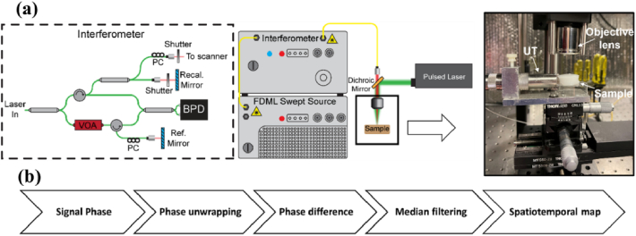
Prior to OCE measurements, the layer thicknesses were confirmed by OCT images of the samples (GAN611C1, Thorlabs Inc., NJ, USA). An OCE system like the one previously described [22,23] was used to detect the NB-induced waves (Fig. 1). An 8X buffered Fourier domain mode-locked (FDML) laser-based OCT system (OMESv2, OptoRes GmbH, Germany) with an A-scan rate of 3.2 MHz, a central wavelength of 1310 nm, and a wavelength scan range of 100 nm was used to detect LSWs. The power on the sample was 33 mW, the axial resolution was 10 µm, the sensitivity was 100 dB, and the displacement stability was ∼11 nm. Data acquisition was performed at 4 GS/s (ATS9373, AlazarTech, Canada). NBs were excited by a Q-switched Nd:YAG laser (Polaris II, New Wave Research, Inc., CA, USA) with 6 ns pulse duration operating in single pulse mode. The excitation wavelength was 1064 nm to match the absorption peak of the Epolight 3072 dye. The pulsed laser beam diameter was 1.2 mm, and measurements were performed at two laser energies of ∼0.75 mJ and 1 mJ. The B-scan trigger of the OCT system was synchronized with both the excitation laser and the oscilloscope to ensure the detection/acquisition of the generated LSW, and the associated PA signal were concurrent with each laser-induced LSW. The excitation and OCT laser beams were coaligned to ensure we were capturing the axially propagating longitudinal shear wave and not a projection of an elastic wave propagating with a lateral component. The focus beam diameters of 68 µm and 59 µm were achieved using a focusing lens (LSM03, Thorlabs Inc., NJ, USA) for the pulsed laser beam and the OCT beam, respectively. OCT imaging after the NB experiments showed no visible damage to the samples.
Fig. 1.
(a) Schematic of OCE system with pulsed laser for LSW excitation and photoacoustic signal detection; PC, polarization controller, VOA, variable optical attenuator, BPD, balanced photodetector, UT, ultrasound transducer. (b) Post-processing flowchart.
The data acquisition was performed in M-mode. Following the nanosecond laser pulse, one B-scan of 5000 A-lines (∼1.56 ms) was captured at a rate of 3.2 MHz. A focused ultrasound transducer (UT), with a 3.5 MHz central frequency and 7.8 mm focal length, was used to acquire the photoacoustic (PA) signal produced by the activation of the nanodroplets. The UT was placed on the side of the sample to avoid interfering with the OCE measurements. Ultrasound gel was used to fill the gap between the transducer and the sample for efficient coupling. The PA signal was amplified using a pulser/receiver amplifier (5073PR, Olympus, Tokyo, Japan) and digitized by an oscilloscope (6000B, Qindao Hantek Electronic Co. Ltd., China).
Data processing was carried out as previously described in [22,23]. The positions of the sample top surface and of the calibration mirror were determined using temporal changes in the signal intensity. Next, the phase was unwrapped in time, and the displacement was calculated from the phase changes. The displacement was differentiated. The temporal profile of the differentiated displacement was then used to visualize the LSW propagations as the spatiotemporal map.
3. Results and discussion
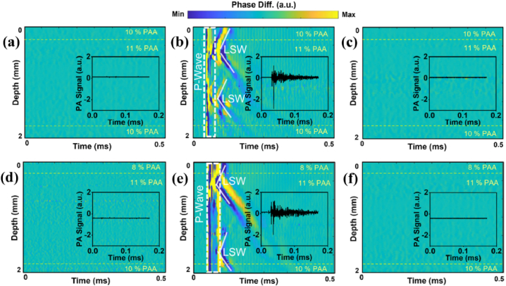
No LSW generation/propagation was observed in either control multilayered samples containing nanodroplets without dye in the middle layer or multilayer blank samples without nanodroplets (Figs. 2(a), (c), (d), and f). Laser excitations of samples 2 and 5 containing NBs laden with the dye resulted in the consistent generation of elastic waves (Fig. 2(b), e). This confirms that the generation of LSWs is due to the activation of NBs. The vertical lines (dashed regions) in Fig. 2(b), (e), at around 45 µs in the spatiotemporal displacement maps correspond to a strong and rapid pressure wave (a.k.a. P-wave) accompanied by LSWs propagating both upward and downward from the activated spots. From the maps of LSW propagation in Fig. 2(b) and (e), the slopes of propagated waves in samples 2 and 5 seem to be equal. Interestingly, two locations with NBs were commonly activated with a single laser pulse. To estimate the elasticity moduli of the samples, using the time-of-flight method [15], the temporal changes of the signal phase were traced along the direction of wave propagation. Then, the slopes was used to approximate the elastic wave velocity at each depth of the phantom. The higher elastic wave velocity is associated with the stiffer region of the sample. In addition to OCE measurements, PA signal generation was recorded in all multilayer phantoms to confirm the excitation of NBs in the middle layer of samples 2 and 5 (insets in Fig. 2(b), e). No PA signal was observed in control samples 1, 3, 4, and 6, as depicted in the plot insets in Fig. 2(a), (c), (d), and f. This is expected as the light-absorptive dye is absent in the control samples and the blank samples.
Fig. 2.
Spatiotemporal displacement maps and inset plots of PA signals in (a) sample 1 with no NBs, (b) sample 2 with dye-loaded NBs in the middle layer, (c) sample 3 with dye-free nanodroplets in the middle layer, (d) sample 4 with no NBs, (e) sample 5 with dye loaded NBs in the middle layer, and (f) sample 6 with dye-free NBs in the middle layer. The laser incident fluence was ∼120 mJ/cm2.
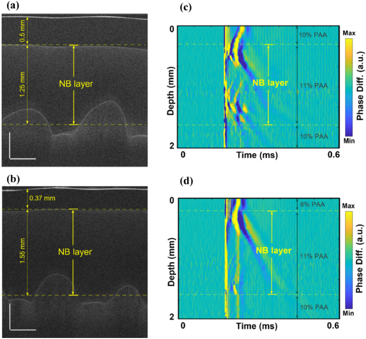
OCT structural images were used to visualize the multilayer structure of the phantoms (Figs. 3(a) and 3(b)). The middle layer with embedded NBs was identified on OCT images and marked on OCE spatiotemporal maps (Figs. 3(c) and 3(d)). Multiple oscillations can be seen in Fig. 3(c), which could be due to oscillations from the collapse of the nanobombs.
Fig. 3.
OCT structural images of (a) sample 2 and (b) sample 5 containing dye-loaded NBs in the middle layer. Scale bars are 0.5 mm. Corresponding spatiotemporal maps of LSW’s propagation in samples 2 (c) and 5 (d).
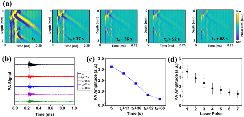
We showed the possibility of repetitively activating the LSWs following consecutive laser pulses at the same location at ∼120 mJ/cm2 in the phantoms containing dye-loaded NBs, albeit with progressively reduced amplitudes of both the medium displacement and the PA signal (Fig. 4). Figure 4(a) shows a series of velocity maps corresponding to the excitation of the NBs located at the same position in the sample. After up to five laser pulses at the same position and even around one minute after the first laser excitation, NB-induced LSWs were still generated and detected. This repetitive activation was further confirmed by the PA signal generation concurrent with each laser-induced LSW (Fig. 4(b)). The plot in Fig. 4(c) shows the decrease in the amplitude of the PA signal after multiple laser excitations. Sample 5 was measured at different lateral locations with repeated laser excitations at each location. Figure 4(d) shows the variations of the PA signal from five different measurements (each at a different location) with seven consecutive laser pulses at each location. The data was averaged for each location and then averaged for all locations. The error bars represent the standard deviation of inter-position averages and show excellent consistency of the generation of NB-induced waves across different locations of the sample.
Fig. 4.
Successive laser excitations at the same location in sample 5 at ∼120 mJ/cm2 laser fluence. (a) The sequence of spatiotemporal displacement maps of repetitive excitations of NBs. (b) Corresponding PA signals after sequential laser pulses. (c) Changes in PA signal amplitude over sequential laser excitations of NBs. (d) Variations of the PA signal from five different measurements (each at a different location) with seven consecutive laser pulses at each position. The error bar is the standard deviation of the inter-position averages.
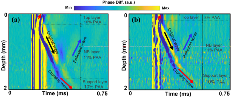
In samples 2 and 5, the NB excitation at higher energies generated stronger LSWs in the middle layer, which propagated into the neighboring top and bottom support layers with no NBs (Fig. 5). The velocity of generated waves only changed when they entered a layer with a different elasticity (i.e., PAA concentration). The amplitude of the generated wave also depends on other parameters such as the size of NBs, the excitation beam diameter, and the location of the NB with respect to the focus of the laser.
Fig. 5.
Spatiotemporal displacement maps of LSW activated by excitation of NBs with laser fluence of 159 mJ∕cm2 in (a) sample 2 with a 10% PAA top layer, 11% PAA and dye-loaded NBs middle layer, and a 10% PAA bottom layer and (b) sample 5 with an 8% PAA top layer, 11% PAA and dye loaded NBs middle layer, and 10% PAA bottom layer.
In the spatiotemporal maps of displacement, this is evident by apparent changes in the slope in Figs. 5(a) and 5(b). In addition, reflections of LSWs at the layer boundaries were also captured. The speed of the reflected wave was equal to that of the original propagating wave.
To quantify the LSW velocity in each layer of the phantom, first, on the spatiotemporal map, a region corresponding to the wave propagation was selected for each phantom layer. Within this region, temporal displacement profiles at all the depth locations are cross correlated with the maximum displacement from the position nearest to the NB activation. The maximum value of the correlation function was then calculated, and the corresponding time delay at each depth of the LSW propagation was obtained. The LSW velocity was then calculated using the least squares linear regression of the time delay versus the propagation distance. The average velocities of the generated LSWs were measured in all three layers for samples 2 and 5. The average LSW velocity for the layers with 8%, 10%, and 11% PAA were 2.68 ± 0.38 m/s, 3.94 ± 0.5 m/s, and 5.25 ± 0.38 m/s, respectively. The Young’s moduli were estimated using the shear wave equation [26] with Poisson’s ratio of 0.49 and assuming 1000 kg/m3 for the density of samples. For the 8%, 10% and 11% PAA, Young’s moduli were estimated as 21.7 ± 5.9 kPa, 46.9 ± 11.7 kPa and 82.4 ± 11.8 kPa, respectively. These values were consistent with our previous measurements [22,23]. The speed of LSWs and Young’s moduli estimated in phantoms agreed with our previous mechanical testing measurements [21–23], confirming elasticity assessment with NBs.
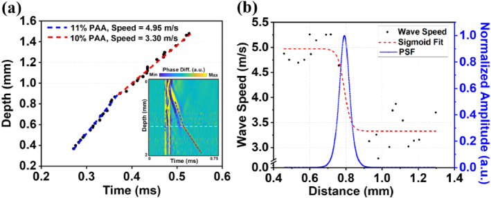
The evaluation of the capability of NB-induced LSWs in differentiating depth-dependent elasticity of the sample, i.e., elasticity resolution, is demonstrated in Fig. 6. First, the depth-dependent wave speed profile was reconstructed by tracking the trajectory of LSW propagation across the layers of the tissue-mimicking multilayer phantom in the spatiotemporal displacement map.
Fig. 6.
Spatial resolution characterization. (a) Depth-time tracking of LSW and inset spatiotemporal map of LSW propagation in sample 2. Blue dashed line represents the linear fit to the wave trajectory in the middle layer and red dashed line shows the linear fit of the wave peak in the third layer of Sample 2. (b) Depth-dependent LSW speed profile measured from (a), a sigmoid fitting, and normalized amplitude of PSF as a function of distance traveled by LSW.
The depth-time changes of the LSW speed were then fit by a sigmoid function model using the following equation.
| (1) |
where and represent the wave speeds in the layers with 11% PAA and 10% PAA, respectively, is the depth position where the speed transition happens and is the width of the speed transition. These fitting parameters were estimated using a standard nonlinear least squares algorithm [27]. The first-order derivative of this sigmoid function with respect to the depth results in a point spread function (PSF) and its full width at half maximum (FWHM) was used to estimate the elasticity resolution [27,28] according to the following equation for FWHM [29].
| (2) |
Depth-time tracking of the main peak of the LSW wavefront and time-of-flight approach allowed the estimation of the average elastic wave velocities (Fig. 6(a)). The blue and red dashed lines approximate the trajectory of LSW peaks in layer with 11% PAA and layer with 10% PAA, respectively. The corresponding spatiotemporal map of displacement (in the inset of Fig. 6(a)) highlights the wave trajectory used to estimate the wave velocity profile and the position of the transition based on the OCT image (white dashed line). Figure 6(b) shows the LSW speed profile, the sigmoid fitting to this wave speed changes, and the first-order derivative of the sigmoid fitting (PSF). The spatial position of the layer interface has been marked in Fig. 6 based on the OCT structural image. The wave speed transition width between two layers was measured from the sigmoid function to be ∼ 0.0186 mm. The FWHM resolution from the PSF peak was calculated to be 0.065 mm using Eq. (2).
To quantify the frequency response of the NB-induced LSWs, the Fast Fourier Transform (FFT) was performed on the spatiotemporal profiles close to the origin of the wave. The average power spectra for two excitation laser fluences are plotted in Fig. 7. Spectral analysis of the original LSW propagating through the NBs layer showed a maximum frequency of ∼70 kHz with a cutoff threshold of −20 dB (Fig. 7), suggesting that a three times finer resolution with bandpass filtering can be achieved. NB activations at different fluences show minimal impact on the resulting frequency content. The stiffness of the NB phantom, however, was previously shown to influence the upper spectral limits of the NB-induced waves, where the high-frequency content (∼ 9 kHz) of the elastic wave in 2% agar was reported 1.8 times higher than in 1% agar, using a cutoff threshold of −30 dB [21]. Although higher frequencies may afford finer mechanical spatial resolution, these waves would travel significantly shorter distances. Therefore, these waves would have to be induced near the transition, which is a case where multiple NB activations would be beneficial. Additionally, speed calculation algorithms can significantly affect the quantified mechanical resolution. We are currently conducting rigorous analyses built on a previous framework [7] assessing the effect of various computational kernel sizes and velocity calculation methods for NB-based elastography.
Fig. 7.
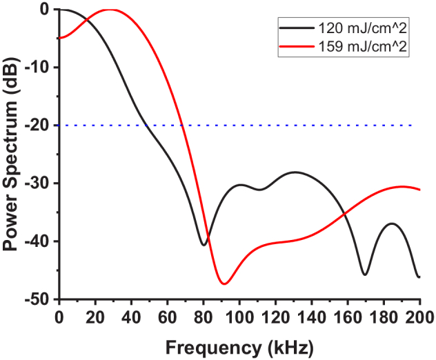
Averaged spectrum of laser-induced LSW with laser fluences of 120 mJ/cm2 and 159 mJ/cm2.
In this research, we conducted phantom experiments to validate the feasibility of the NB method for inhomogeneous layered structures. The use of different activation energies was to demonstrate the versatility of the NBs, but more specifically, for laser safety issues to ensure compliance with laser exposure regulations. Successive NB activations from a single spot in the sample provide the possibility of the potential application of NB OCE in the assessment of the biomechanical properties of biological tissues in longitudinal studies. It is also important to note that the concentration of the NBs should be controlled to minimize the generation of multiple waves. Otherwise, the generation of multiple simultaneous waves can hinder tracking the wave propagation and calculation of the wave speed.
The formation of microbubbles within tissue is a well-documented process [30]. However, our approach uniquely employs PFC nanodroplets, significantly lowering the energy required for bubble activation. Additional investigations are warranted to understand the impact of thermal effects and shock waves on tissue and cellular damage. Conducting safety studies forms an integral part of our future work and is a prerequisite before in vivo experiments. The results of this study show that the nanobomb technique has the potential for measuring the elasticity of multicellular structures (e.g., cellular spheroids) and small tissue samples, e.g., millimeter-scale biopsies, particularly where high mechanical resolution is imperative. As we discussed in our previous research [23], depending on the application, because of their favorable size in the range of 250-500 nm, nanobombs can be introduced into tissues via direct injections akin to theranostics agents used for magnetic resonance, ultrasound, and computed tomography [31–34], or via a systemic administration followed by extravasation to cancer tissues due to enhanced permeability and retention (EPR) effect [35–37]. At present, we envision the most immediate application of this technique to be in the study of cellular structures, e.g., organoids, and safety testing is currently ongoing to ensure safe in vivo NB measurements.
4. Conclusion
In this study, we demonstrated the first use of NB-induced elastic waves to characterize the depth-wise gradient in the elasticity of multilayer phantoms with micrometer-scale mechanical resolution. Optical activation of NBs by a nanosecond laser pulse results in the liquid-to-gas phase transition of the nanobombs, producing highly localized LSWs, which can propagate from the activation site into neighboring layers of the phantoms. The generated LSWs were captured by ultrafast OCE. The shear wave velocity was used to estimate the elasticity of the different layers of the tissue-mimicking phantoms, which were in good agreement with mechanical testing and previously reported elasticity values. Propagation of NB-induced LSWs between phantom layers allowed measurement of the elasticity even in layers with no NBs. These results demonstrate the potential of an all-optical OCE capable of characterizing the depth-dependent properties of layered tissues. Future work will be focused on applications in the biological specimen and further optimization of NBs for adherence to laser safety limits.
Funding
National Institutes of Health10.13039/100000002 (P30EY07551, R21CA231561).
Disclosures
MS and KVL have financial interests in ElastEye LLC., which is not directly related to this work.
Data availability
The datasets generated for this study can be made available upon reasonable request from the authors.
References
- 1.Lee G.Y., Lim C.T., “Biomechanics approaches to studying human diseases,” Trends Biotechnol. 25(3), 111–118 (2007). 10.1016/j.tibtech.2007.01.005 [DOI] [PubMed] [Google Scholar]
- 2.Zvietcovich F., Larin K.V., “Wave-based optical coherence elastography: The 10-year perspective,” Prog. Biomed. Eng. 4(1), 012007 (2022). 10.1088/2516-1091/ac4512 [DOI] [PMC free article] [PubMed] [Google Scholar]
- 3.Singh M., Zvietcovich F., Larin K.V., “Introduction to optical coherence elastography: tutorial,” J. Opt. Soc. Am. A 39(3), 418–430 (2022). 10.1364/JOSAA.444808 [DOI] [PMC free article] [PubMed] [Google Scholar]
- 4.Sticker M., “Quantitative differential phase measurement and imaging in transparent and turbid media by optical coherence tomography,” Opt. Lett. 26(8), 518 (2001). 10.1364/OL.26.000518 [DOI] [PubMed] [Google Scholar]
- 5.Song S., “Strategies to improve phase-stability of ultrafast swept source optical coherence tomography for single shot imaging of transient mechanical waves at 16 kHz frame rate,” Appl. Phys. Lett. 108(19), 191104 (2016). 10.1063/1.4949469 [DOI] [PMC free article] [PubMed] [Google Scholar]
- 6.Leartprapun N., “Spatial localization of mechanical excitation affects spatial resolution, contrast, and contrast-to-noise ratio in acoustic radiation force optical coherence elastography,” Biomed. Opt. Express 10(11), 5877–5904 (2019). 10.1364/BOE.10.005877 [DOI] [PMC free article] [PubMed] [Google Scholar]
- 7.Kirby M.A., “Spatial resolution in dynamic optical coherence elastography,” J. Biomed. Opt. 24(09), 1–16 (2019). 10.1117/1.JBO.24.9.096006 [DOI] [PMC free article] [PubMed] [Google Scholar]
- 8.Aglyamov S.R., “The dynamic deformation of a layered viscoelastic medium under surface excitation,” Phys. Med. Biol. 60(11), 4295 (2015). 10.1088/0031-9155/60/11/4295 [DOI] [PMC free article] [PubMed] [Google Scholar]
- 9.Wang S., “Assessing the mechanical properties of tissue-mimicking phantoms at different depths as an approach to measure biomechanical gradient of crystalline lens,” Biomed. Opt. Express 4(12), 2769 (2013). 10.1364/BOE.4.002769 [DOI] [PMC free article] [PubMed] [Google Scholar]
- 10.Liu H.C., “Acoustic force elastography microscopy,” IEEE Trans. Biomed. Eng. 70(3), 841–852 (2023). 10.1109/TBME.2022.3203435 [DOI] [PMC free article] [PubMed] [Google Scholar]
- 11.Khanna S.M., Sears R.E., Tonndorf J., “Some properties of longitudinal shear waves: a study by computer simulation,” J. Acoust. Soc. Am. 43(5), 1077–1084 (1968). 10.1121/1.1910942 [DOI] [PubMed] [Google Scholar]
- 12.Catheline S., Benech N., “Longitudinal shear wave and transverse dilatational wave in solids,” J. Acoust. Soc. Am. 137(2), EL200–EL205 (2015). 10.1121/1.4907742 [DOI] [PubMed] [Google Scholar]
- 13.Zhu J., “Longitudinal shear wave imaging for elasticity mapping using optical coherence elastography,” Appl. Phys. Lett. 110(20), 201101 (2017). 10.1063/1.4983292 [DOI] [PMC free article] [PubMed] [Google Scholar]
- 14.Zhu J., “Coaxial excitation longitudinal shear wave measurement for quantitative elasticity assessment using phase-resolved optical coherence elastography,” Opt. Lett. 43(10), 2388–2391 (2018). 10.1364/OL.43.002388 [DOI] [PubMed] [Google Scholar]
- 15.Zvietcovich F., “Longitudinal shear waves for elastic characterization of tissues in optical coherence elastography,” Biomed. Opt. Express 10(7), 3699–3718 (2019). 10.1364/BOE.10.003699 [DOI] [PMC free article] [PubMed] [Google Scholar]
- 16.Liang X., “Acoustomotive optical coherence elastography for measuring material mechanical properties,” Opt. Lett. 34(19), 2894 (2009). 10.1364/OL.34.002894 [DOI] [PMC free article] [PubMed] [Google Scholar]
- 17.Ahmad A., “Magnetomotive optical coherence elastography using magnetic particles to induce mechanical waves,” Biomed. Opt. Express 5(7), 2349 (2014). 10.1364/BOE.5.002349 [DOI] [PMC free article] [PubMed] [Google Scholar]
- 18.Li C., “Noncontact all-optical measurement of corneal elasticity,” Opt. Lett. 37(10), 1625 (2012). 10.1364/OL.37.001625 [DOI] [PubMed] [Google Scholar]
- 19.Das S., “Laser-induced elastic wave classification: thermoelastic versus ablative regimes for all-optical elastography applications,” J. Biomed. Opt. 25(03), 1–13 (2020). 10.1117/1.JBO.25.3.035004 [DOI] [PMC free article] [PubMed] [Google Scholar]
- 20.Li C., “Laser induced surface acoustic wave combined with phase sensitive optical coherence tomography for superficial tissue characterization: a solution for practical application,” Biomed. Opt. Express 5(5), 1403 (2014). 10.1364/BOE.5.001403 [DOI] [PMC free article] [PubMed] [Google Scholar]
- 21.Liu C.H., “Nanobomb optical coherence elastography,” Opt. Lett. 43(9), 2006–2009 (2018). 10.1364/OL.43.002006 [DOI] [PMC free article] [PubMed] [Google Scholar]
- 22.Liu C.H., “Longitudinal elastic wave imaging using nanobomb optical coherence elastography,” Opt. Lett. 44(12), 3162–3165 (2019). 10.1364/OL.44.003162 [DOI] [PMC free article] [PubMed] [Google Scholar]
- 23.Boerner P., “Repetitive optical coherence elastography measurements with blinking nanobombs,” Biomed. Opt. Express 11(11), 6659–6673 (2020). 10.1364/BOE.401734 [DOI] [PMC free article] [PubMed] [Google Scholar]
- 24.Nevozhay D., “Spatiotemporally controlled nano-sized third harmonic generation agents,” Biomed. Opt. Express 10(7), 3301–3316 (2019). 10.1364/BOE.10.003301 [DOI] [PMC free article] [PubMed] [Google Scholar]
- 25.Mitcham T.M., “Effect of perfluorocarbon composition on activation of phase-changing ultrasound contrast agents,” Med. Phys. 49(4), 2212–2219 (2022). 10.1002/mp.15564 [DOI] [PMC free article] [PubMed] [Google Scholar]
- 26.Szabo T.L., Wu J., “A model for longitudinal and shear wave propagation in viscoelastic media,” J. Acoust. Soc. Am. 107(5), 2437–2446 (2000). 10.1121/1.428630 [DOI] [PubMed] [Google Scholar]
- 27.Rouze N.C., “Parameters affecting the resolution and accuracy of 2-D quantitative shear wave images,” IEEE Trans Ultrason Ferroelectr Freq Control 59(8), 1729–1740 (2012). 10.1109/TUFFC.2012.2377 [DOI] [PMC free article] [PubMed] [Google Scholar]
- 28.Hepburn M.S., “Analysis of spatial resolution in phase-sensitive compression optical coherence elastography,” Biomed. Opt. Express 10(3), 1496–1513 (2019). 10.1364/BOE.10.001496 [DOI] [PMC free article] [PubMed] [Google Scholar]
- 29.Qian X., “Multi-functional ultrasonic micro-elastography imaging system,” Sci. Rep. 7(1), 1230 (2017). 10.1038/s41598-017-01210-8 [DOI] [PMC free article] [PubMed] [Google Scholar]
- 30.Weg P.-M.,, Graz K.-F.-U., “Mechanisms of femtosecond laser nanosurgery of cells and tissues,” 2005.
- 31.Lazaro-Carrillo A., “Tailor-made PEG coated iron oxide nanoparticles as contrast agents for long lasting magnetic resonance molecular imaging of solid cancers,” Mater. Sci. Eng., C 107, 110262 (2020). 10.1016/j.msec.2019.110262 [DOI] [PubMed] [Google Scholar]
- 32.Song D., “Overcoming hypoxia-induced chemoresistance to cisplatin through tumor oxygenation monitored by optical imaging,” Nanotheranostics 3(2), 223–235 (2019). 10.7150/ntno.35935 [DOI] [PMC free article] [PubMed] [Google Scholar]
- 33.Min K.H., “pH-controlled gas-generating mineralized nanoparticles: a theranostic agent for ultrasound imaging and therapy of cancers,” ACS Nano 9(1), 134–145 (2015). 10.1021/nn506210a [DOI] [PMC free article] [PubMed] [Google Scholar]
- 34.Choi D., “Iodinated echogenic glycol chitosan nanoparticles for X-ray CT/US dual imaging of tumor,” Nanotheranostics 2(2), 117–127 (2018). 10.7150/ntno.18643 [DOI] [PMC free article] [PubMed] [Google Scholar]
- 35.Fang J., Islam W., Maeda H., “Exploiting the dynamics of the EPR effect and strategies to improve the therapeutic effects of nanomedicines by using EPR effect enhancers,” Adv. Drug Delivery Rev. 157, 142–160 (2020). 10.1016/j.addr.2020.06.005 [DOI] [PubMed] [Google Scholar]
- 36.Matsumura Y.,, Maeda H., “A new concept for macromolecular therapeutics in cancer chemotherapy: mechanism of tumoritropic accumulation of proteins and the antitumor agent smancs,” Cancer Res 46(12 Pt 1), 6387 (1986). [PubMed] [Google Scholar]
- 37.Torchilin V, “Tumor delivery of macromolecular drugs based on the EPR effect,” Adv. Drug Delivery Rev. 63(3), 131–135 (2011). 10.1016/j.addr.2010.03.011 [DOI] [PubMed] [Google Scholar]
Associated Data
This section collects any data citations, data availability statements, or supplementary materials included in this article.
Data Availability Statement
The datasets generated for this study can be made available upon reasonable request from the authors.


