Abstract
This paper introduces the first integrated real-time intraoperative surgical guidance system, in which an endoscope camera of da Vinci surgical robot and a transrectal ultrasound (TRUS) transducer are co-registered using photoacoustic markers that are detected in both fluorescence (FL) and photoacoustic (PA) imaging. The co-registered system enables the TRUS transducer to track the laser spot illuminated by a pulsed-laser-diode attached to the surgical instrument, providing both FL and PA images of the surgical region-of-interest (ROI). As a result, the generated photoacoustic marker is visualized and localized in the da Vinci endoscopic FL images, and the corresponding tracking can be conducted by rotating the TRUS transducer to display the PA image of the marker. A quantitative evaluation revealed that the average registration and tracking errors were 0.84 mm and 1.16°, respectively. This study shows that the co-registered photoacoustic marker tracking can be effectively deployed intraoperatively using TRUS+PA imaging providing functional guidance of the surgical ROI.
Keywords: medical robots and systems, software-hardware integration for robot systems, surgical guidance system, transrectal ultrasound imaging, photoacoustic imaging
I. Introduction
Prostatectomy, a surgical procedure in which the entire prostate gland is completely removed, is one of the common approaches for treating prostate cancer. Different surgical approaches have been adopted for the procedure including radical prostatectomy, and the procedure with perineal approach [1], [2]. In particular, robot-assisted laparoscopic prostatectomy (RALP), in which the surgeon moves the robotic arm through a computerized control system (e.g., da Vinci surgical robot), counts for over 80% of the entire radical prostatectomy procedures performed in the United States, as its minimally invasive surgical approach shortens the recovery time and reduce the risk of post-operative complications [3]–[5]. Although robot-assisted radical prostatectomy has increased the surgical dexterity and efficacy over conventional approach, the visualization of the morphological structure and functional characteristics (e.g., neuronal network structure surrounding the prostate gland, prostate cancer) of the surgical region-of-interest (ROI) is determined by solely on the endoscopic camera. The camera view cannot distinguish between healthy and cancerous tissue, nor can it determine the location of anatomical structures such as the nerves. Thus, there has been an emerging demand for additional imaging modalities that can provide an advanced interpretation capability [6]–[9].
Transrectal ultrasound (TRUS) imaging is the most widely used prostate imaging modality since it provides real-time imaging and is easy to be implemented with RALP [10]–[12]. In addition, photoacoustic (PA) imaging can be combined to provide additional functional molecular imaging [13]–[16]. Thus, the use of transrectal ultrasound and photoacoustic imaging with RALP has the benefit of providing the surgeon additional tools to improve oncological and functional outcomes.
There have been several endeavors to integrate TRUS imaging with RALP. In particular, Mohareri, et al. [10] developed a real-time ultrasound image guidance system during the prostatectomy procedure in which a robotized TRUS system automatically tracks the surgical instrument of a da Vinci surgical robot. The study performs the calibration between the TRUS transducer and surgical tool tip by determining the tool tip position using the highest acoustic intensity reflected from the tip. Moradi, et al. [17] further developed the system by incorporating PA imaging modality by attaching the optical fiber to the tool tip. Although these approaches have paved the way for using TRUS imaging with RALP procedure, there are several limitations to the approach. In particular, detecting the surgical tool tip accurately in the ultrasound image is challenging, especially in the elevational direction, and is dependent on the shape of the surgical instrument and the manner in which it is pressed on the tissue. This lowers the calibration performance.
To overcome these issues, a photoacoustic marker (PM) technique was recently proposed by Cheng, et al. [18]. With this method, a laser source is used as the marker that can be detected by both the camera and the photoacoustic sensor. By having multiple PMs, a frame transformation between the TRUS and camera frames can be calibrated preoperatively, to enable the TRUS transducer to automatically track the PM during the operation (Fig. 1). One can leverage this by attaching a laser source to the surgical tool and aim the laser point to the tool tip, to enable TRUS+PA image-guidance at a specific imaging plane-of-interest. However, this technology has been evaluated via off-line processing, which has not yet validated in real-time operation for surgical intervention.
Fig. 1. Conceptual illustration of registration and tracking using photoacoustic markers (PM).
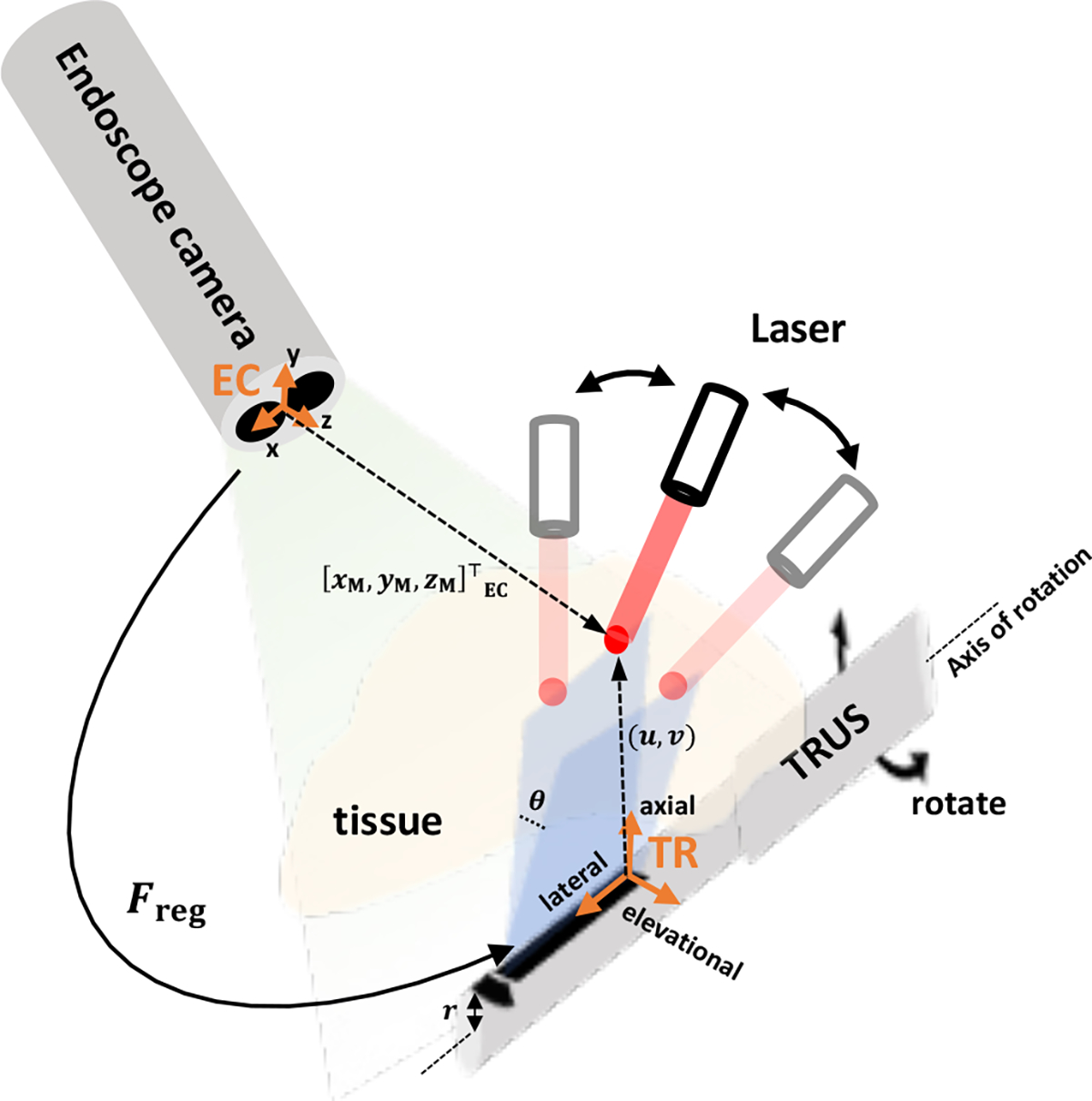
The registration indicates the frame transformation between the endoscopic stereo camera frame (EC) and the TRUS frame (TR). The tracking of PM is conducted by rotating the TRUS transducer based on the given . and represent the positions of PM in EC frame and 2D PA image, respectively. is the radius of TRUS transducer, and is the rotation angle.
In this paper, we present the first integrated implementation and demonstration of a TRUS+PA image-guided real-time intraoperative surgical guidance system based on the PM technique. A pulsed-laser-diode (PLD) is used as the laser source, to perform the registration between the fluorescence (FL) image of the da Vinci endoscopic camera and the TRUS image. The tracking is conducted to display the in-plane US+PA images where the laser is aiming at the ROI. This paper is structured as follows: In Section 2, the system architecture, functional architecture along with sub-module structures, and algorithms are listed and described. In Section 3, we presented the experimental setup, the resultant FL and US+PA images, as well as a quantitative evaluation. Lastly, Section 4 summarizes our method and discusses its limitations and further applications.
II. Methods
In this system, the tracking of the PM by the TRUS transducer is enabled by generating the PMs with laser to the surgical region-of-interest. The PMs are detected by the da Vinci fluorescence endoscope camera (Firefly, Intuitive Surgical, Inc., Sunnyvale, CA, USA), and its 3-dimensional (3D) position is localized with respect to FL frame (i.e. EC). The position of the PM is then transformed to TRUS coordinate system (i.e., TR) and the associate rotation angle is derived accordingly. As a result, the actuator attached to the TRUS transducer will rotate to the desired angle so that the resultant in-plane US+PA images are displayed. A detailed description of the system is given in the following subsections.
A. System architecture
The overall system architecture is shown in Fig. 2. The proposed surgical guidance system is composed of several modules including the host computer, da Vinci surgical robot, a pulsed-laser system, an actuator control module, and a US+PA imaging system. The black arrows indicate the signaling direction between the connected modules. In other words, the host computer will start the PM illumination by starting the laser excitation through triggering the USB-connected laser system. The US+PA imaging system is synchronized with the laser system, and provides the real-time US+PA imaging upon laser excitation. The endoscopic stereo camera images are streamed and transferred to the host computer for real-time 3D PM localization. The actuator control module and the host computer are connected through TCP/IP protocol for the tracking control, through which the rotation angle value is transferred from the host.
Fig. 2. The overall system architecture of TRUS+PA image-guided surgical guidance system.
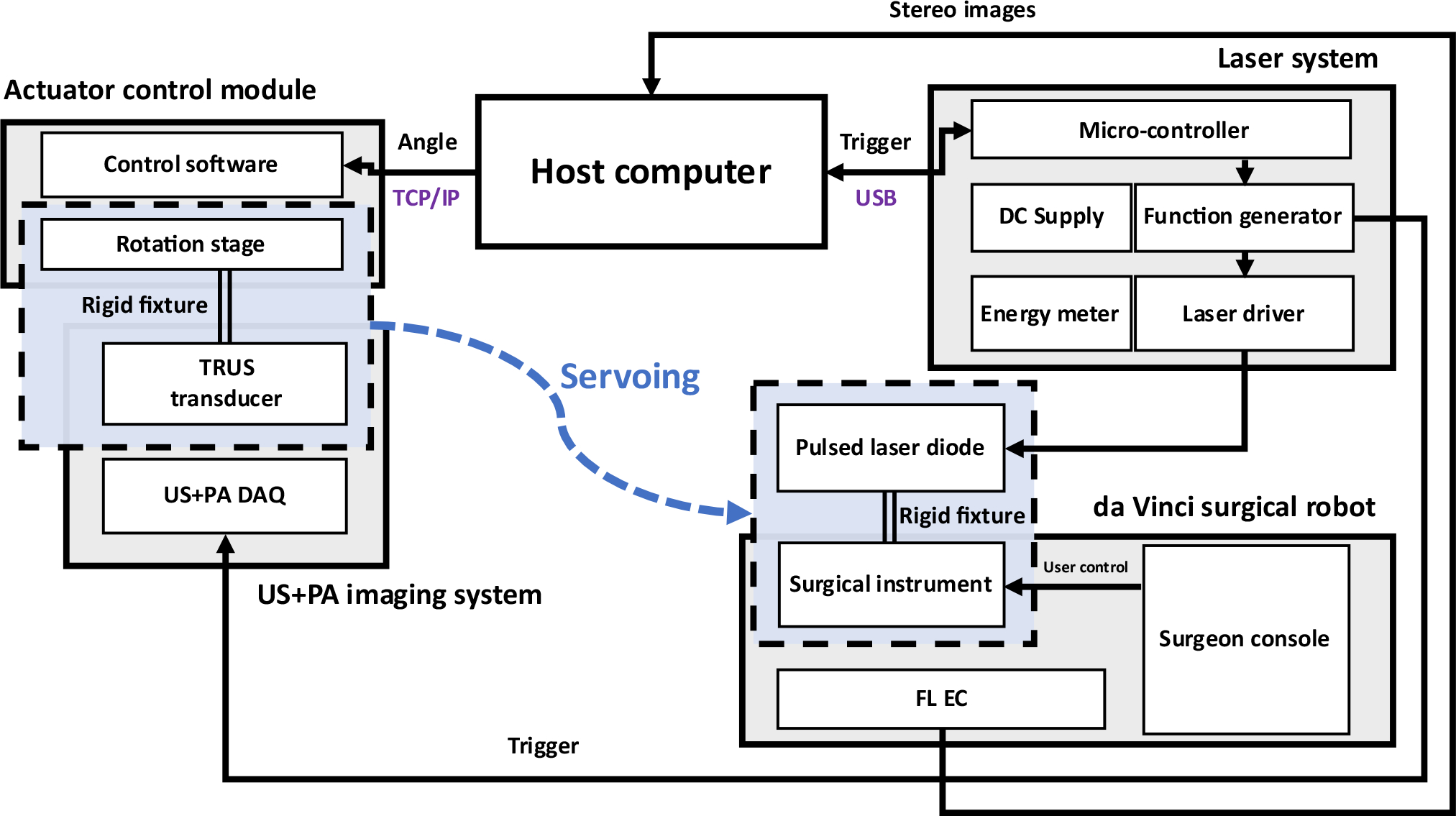
DAQ: Data acquisition system; FL EC: Fluorescence endoscopic camera
Fig. 3 shows the functional flowchart of the proposed system. The solid arrows indicate the data transfer direction. Note that each module runs concurrently and communicates with other modules in the ROS platform. The host controls the laser excitation (i.e., PM generation), stereo image processing, PM localization, frame transformation, and angle calculation. The laser system generates the laser pulses according to the message provided by the host.
Fig. 3. Functional flowchart of the system.
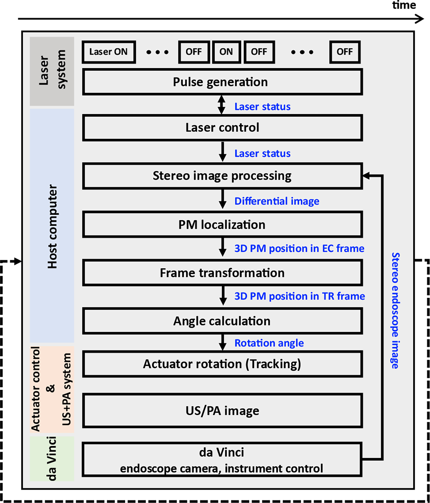
The blue words indicate the transferred data.
B. Laser control system
A fiber-coupled PLD (QSP-785-4, QPhotonics LLC, Ann Arbor, MI, USA) driven by a pulsed laser driver (LDP-V, PicoLAS GmbH, Germany) is used to generate a 785 nm laser beam. The driver is operated by a function generator (SDG2042X, SIGLENT, Shenzhen, China) for excitation. The excitation parameters of the laser are: 5 kHz, pulse-repetition-frequency (PRF); 1 usec, pulse width; 4 A, input current. Here, we heuristically optimized the laser excitation parameter by comparing the images in which the PM can be simultaneously detectable in both FL camera and the TRUS transducer. Since the light diverges at the end of the fiber when it is excited, an anti-reflective (AR) coated fixed convex lens focused at 24mm with 5mm depth-of-focus, is attached at the output port of the PLD to focus the laser beam at the target surface.
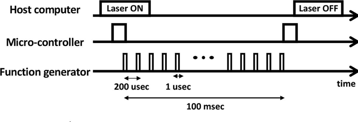
Fig. 4 illustrates the timing diagram of the laser excitation. Initially, the host sends a message which indicates starting of the laser excitation (i.e., laser ON), to the micro- controller generating corresponding TTL trigger to the function generator. Consequently, the function generator drives the laser by producing the excitation pulses. Note that by the time when the laser excitation message is received by the micro-controller (i.e., laser ON), 250 excitation pulses are generated, so that the imaging module can average the PA images to increase the signal-to-noise ratio (SNR). After all the excitation pulses are generated, a output trigger is sent back to the host computer via micro-controller, to indicate the laser excitation is finished (i.e., laser OFF).
Fig. 4. Timing diagram of laser excitation.
C. PM generation
The photoacoustic marker (PM) is generated based on the photoacoustic effect by the laser excitation, where the optical absorber converts the excited light energy into thermal energy to generate corresponding acoustic pressure which can be detected by a clinical ultrasound transducer. Note that the PM can also be detected by the fluorescence imaging. In this study, PM was generated by a single pulsed laser excitation and corresponding acoustic wave was received by the TRUS transducer to reconstruct the PA image.
D. PM localization algorithm
To perform frame registration and tracking, the PMs are localized in each modality (i.e., FL and PA images).
1). Fluorescence imaging
The da Vinci endoscopic stereo camera is calibrated with MATLAB stereo camera calibration toolbox (MathWorks Inc., Natick, MA, USA). The PM is highlighted in the left and right camera views by eliminating the background by subtracting the two consecutive images with and without the laser excitation (Fig. 5). Here, the images are pre-processed by labeling with the laser status (i.e., laser ON or laser OFF), and the program subtracts the two consecutive images if the state of the laser is changed. Next, the highlighted PM is first segmented with a certain intensity threshold and fitted to an ellipse to compute its intensity-weighted centroid within the ellipse region. As a result, the 3D position of the PM is derived by triangulating the two centroid points obtained from both cameras.
Fig. 5. PM localization algorithm in FL imaging modality.
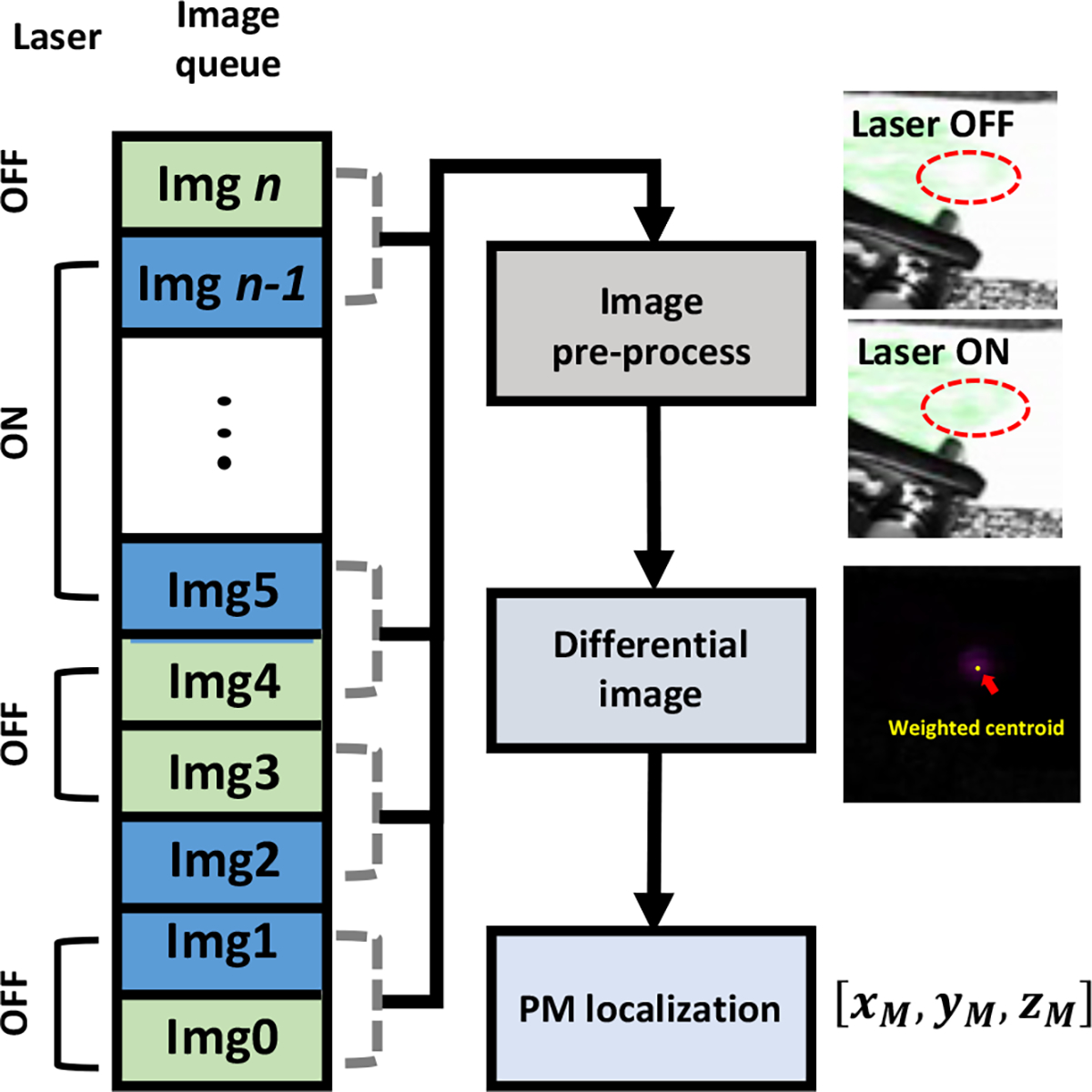
Block diagram representing the PM localization workflow. The pre-precoessed images (i.e., FL images without and with the laser illumination) are subtracted to highlight the PM (i.e., Laser ON – Laser OFF), and the weighted centroid point was defined as the PM position..
Here, the image capture system streams the FL image with 18~20Hz frame rate, which significantly exceeds the respiration rate that a normal adults have at rest (e.g., approximately 0.2 Hz). In addition, a previous literature reporting the motion frequency of human eye and finger shows that the speed of motion when he/she tracks a visual target remains at approximately 5~8Hz [19], which will be potentially identical to the speed of manipulating the surgical instrument during surgery. Thus, the subtraction algorithm will be sufficiently effective as the interval between the two subtracted images (i.e., images with and without the laser spot) is much shorter than the respiration interval and hand motion interval (i.e., 50 msec, 5 sec, 200 msec for the intervals between the two images, consecutive respiration, and hand motion, respectively). Furthermore, the subtraction algorithm is simple to be implemented, and robust to be applied to not only prostate surgery, but also other organs as it only highlights the PM regardless of other context within the image (e.g., organ structure, surgical instruments).
2). Photoacoustic imaging
A photoacoustic image is first reconstructed with a custom program which conducts radio-frequency (RF) domain averaging over total acquisitions (i.e., 250), delay-and-sum (DAS) beamforming, and post processing for image display. A low-pass filter is applied to remove the high-frequency noise component. Consequently, the PM was segmented from the image by applying the intensity and pixel size threshold. The threshold was determined manually based on the size of the PM (i.e., 1 ~ 2 mm in diameter). Note that a robust PM segmentation algorithm is under development for further implementation.
E. Actuator control
The actuator control module consists of a one degree-of-freedom motorized rotation stage (PRM1Z8, Thorlabs, Newton, NJ, USA), a dedicated driver (KDC101, Thorlabs, Newton, NJ, USA) which is controlled with a custom LabVIEW (National Instrument, Austin, TX, USA) program. The actuator has a maximum rotation velocity of 25°/sec, with a calculated resolution of 0.0005°. In this study, the rotation velocity is set to the maximum to ensure fast-tracking of the PM. In addition, a 3D-printed fixture mount is used to rigidly attach the TRUS transducer to the actuator.
F. Registration
The registration is conducted before performing the tracking. At least three-point pairs in FL and PA images are acquired and the registration transformation is computed using Horn’s method [20]. Based on the PM localization algorithm in each imaging modality, the 3D position of the PM with respect to fluorescence imaging (i.e., EC) is calculated in the cartesian coordinate system (i.c.,). The position of PM in the PA imaging frame was represented as , which indicates the lateral and axial positions of the pixel in 2D photoacoustic image and the current angle of the rotation stage, respectively (Fig. 1). These are converted to the cartesian coordinate based on the equation below:
| (1) |
where is the radius of the TRUS transducer. , , and match with lateral, elevational, and axial direction of TR frame.
Unlike FL imaging, manual maneuvering of the rotation stage is conducted in order to obtain the in-plane photoacoustic signal from the PM. By comparing the multiple images with adjacent orientations, the image with the highest intensity calculated from each centroid is regarded as the in-plane image, and corresponding coordinates (i.e., ) are used for the frame registration.
G. Tracking
The aforementioned PM position in FL imaging is transformed to TRUS imaging coordinate based on the transformation matrix calculated from the registration. Thus, the position of the PM in the TRUS imaging coordinate will be
| (2) |
where is the frame transformation matrix between EC and TR frames (Fig. 1).
To perform the tracking in which the TRUS transducer rotates to the desired angle to display in-plane US+PA image, the angle is derived from cartesian coordinate system:
| (3) |
H. Dual-modal US+PA imaging system
Ultrasound and photoacoustic images are acquired to visualize the morphological structure and the PMs, respectively. Here, a bi-plane TRUS transducer (BPL 9–5/55, BK Medical, Peabody, MA, USA) is connected to a commercial diagnostic ultrasound machine (SonixTouch and SonixDAQ, Ultrasonix Medical Corp., Canada) for dual-modal US+PA imaging. The specification of the transducer is: 6.5 MHz, center frequency; 0.43 mm, element pitch; 128, number of elements; 10 mm, transducer radius . The acoustic RF data was obtained with 40 MHz sampling frequency. For PA imaging, 250 images are averaged to increase the signal-to-noise ratio (SNR).
I. ex-vivo tissue preparation
These experiments are performed using fresh ex-vivo chicken breast tissue. To enable PM visualization from both imaging modalities (i.e., FL and PA images), the tissue sample is stained with an indocyanine green (ICG) dye (TCI, Tokyo, Japan) solution in 2 mg/ml concentration. The selection of the dye is based on the fact that the ICG has its peak absorbance and emission at 780nm and 805nm wavelengths, respectively. This matches well with the excitation laser wavelength and the emission filter installed in the da Vinci FL endoscopic camera. Note that the staining is performed for 10 minutes based on the maximum downtime that will not hamper the surgical procedure.
J. Performance evaluation
To evaluate the tracking performance, a quantitative evaluation is performed. Based on the frame registration result, the 3D positions of multiple PMs measured in the FL image are transformed to the TRUS image frame (i.e., TR), and the errors are measured by calculating the Euclidean distance and the relative angle from corresponding ground truth PM positions in the TRUS image frame. The ground truth position of the PM is collected similarly to what was performed in registration, in which the in-plane image is determined by manually maneuvering of the rotation stage. The Euclidean distance is measured as follows:
| (4) |
where are the tracked and ground truth PM positions in TRUS image frame, respectively.
III. Results
A. Experimental setup
Fig. 6 shows the experimental setup with the da Vinci endoscopic camera and TRUS transducer mimicking a surgical procedure. An ICG dye-stained ex vivo chicken breast tissue is supported by a phantom holder, and the TRUS transducer fixed to the actuator is located underneath and placed in contacted with the tissue for the US+PA imaging. The endoscopic camera captures the experimental scene from the top. Blue light indicates the fluorescence illumination from the camera module. The PLD emits the laser to generate the PMs on the surface.
Fig. 6. Ex-vivo Experimental setup mimicking practical surgical scenario.
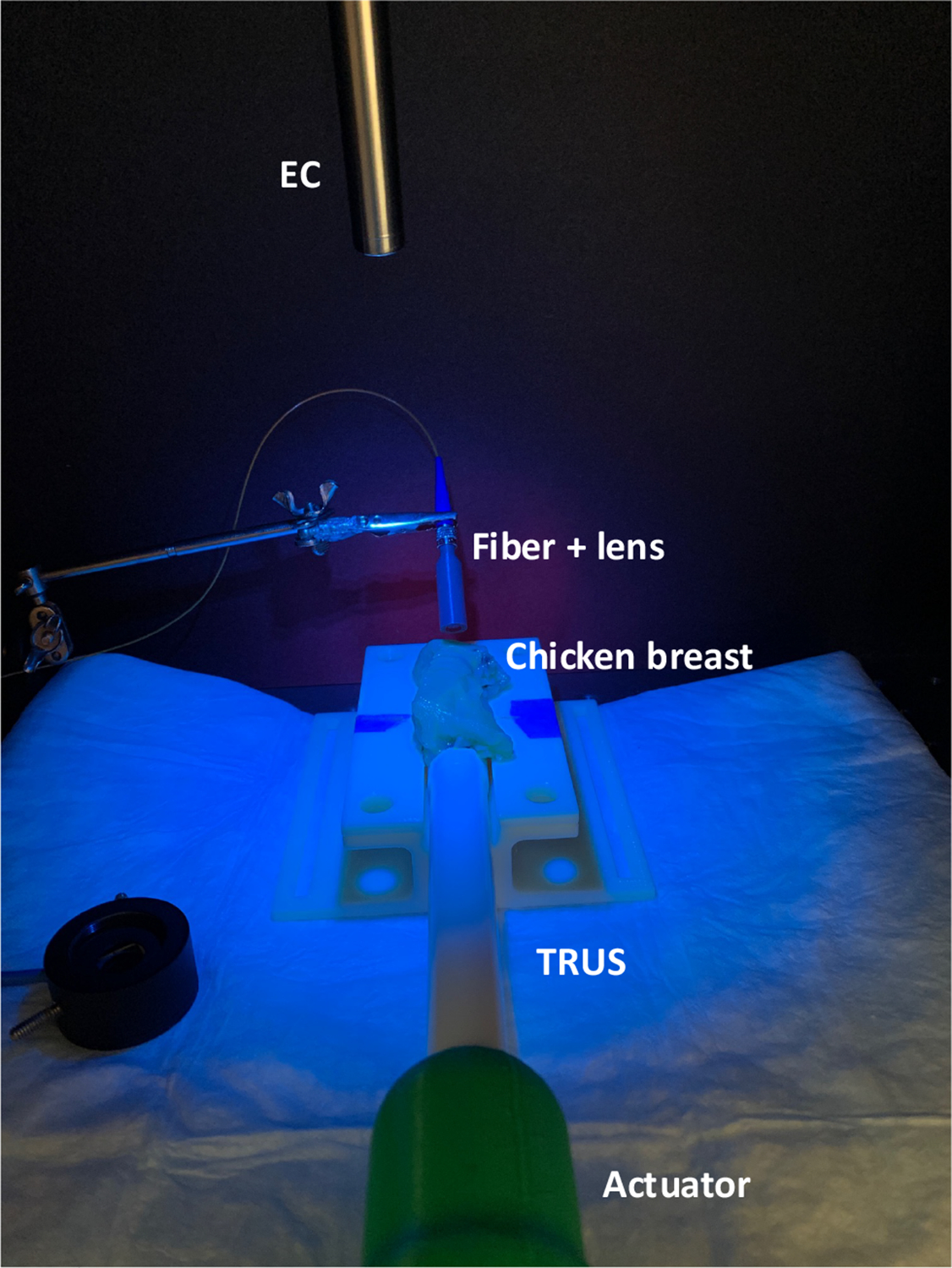
EC: Endoscopic stereo camera; TRUS: Transrectal ultrasound transducer
B. PM visualization in FL and PA imaging modalities
The PM generated by the PLD is visualized in both FL and PA imaging modalities (Fig. 7). The fine-tuning of the laser excitation parameters enabled creation of a clear marker in FL images shown as a brighter green dot compared to another region that is not excited. Moreover, the marker is also presented in the normalized PA image at the surface of the chicken breast indicated with the bright solid line shown in b-mode US image. Note that the images are captured after conducting the registration, and the marker is tracked by rotating the TRUS transducer
Fig. 7. Visualization of PMs in both FL and US+PA imaging modalities after registration and tracking.

The photoacoustic image was overlaid on the grayscale ultrasound image.
C. Quantitative evaluation
Several quantitative evaluations were conducted to assess the performance of the proposed system.
First of all, we have evaluated the accuracy of the centroid detection in endoscopic camera. In particular, the laser is aimed at a random corner of the checkerboard, and the Euclidean distance between the detected centroid and the corner position was measured. Note that the Harris corner detection algorithm, a standard algorithm for corner detection, was used to calculate the corner position within the checkerboard. Corner position was measured without any laser excitation. Five measurements were collected, and the accuracy of centroid detection algorithm was 0.54±0.12 mm.
In addition, the evaluation of registration and tracking were conducted with three different position sets, and five tracking tests were performed at each position set. Fig. 8 shows the representative plot of position set #3, showing the positions of detected PMs and corresponding ground truth positions (i.e., blue and red dots, respectively). Note that the TR frame is set as the origin. Quantitative measurement of Euclidean distance represents the registration errors: {0.67±0.18, 1.09±0.38, 0.77±0.34} mm for the three position sets (Table I). In addition, the expected rotation angle is also derived to evaluate the error of tracking: {1.13±0.13, 1.21±0.43, 1.14±0.33} degrees for the three position sets (Table I). The Euclidean distances between the ground truth and tracked PMs are within acceptable range, by the fact that a prostate tumor of 5mm diameter or less is considered to be insignificant. The registration and tracking performance are determined by how accurately the PMs are localized from both FL and PA images. In PA imaging, the resolution of the rotation actuator (i.e., 0.0005°) is the dominant factor for accurate localization of the PM as it determines if the PM is in-plane to the TRUS imaging direction. For instance, an actuator with a coarse rotation resolution (e.g., 1°) will not obtain the comparable tracking performance obtained in this experiment. Besides, the slice thickness of the TRUS transducer defines the sensitivity in which the TRUS transducer can receive the off-axis PA signals from the PM which is within the slice thickness. Note that the measured slice thickness of the TRUS transducer is 5.4°. In other words, when the TRUS transducer is not oriented to the position of the PM, it can still be detected when the orientation of the TRUS transducer is within the range of [−2.7, 2.7]°.
Fig. 8. The positions of tracked PMs (Blue dots) and corresponding ground truth positions (Red dots) with respect to TRUS-PA coordinate.
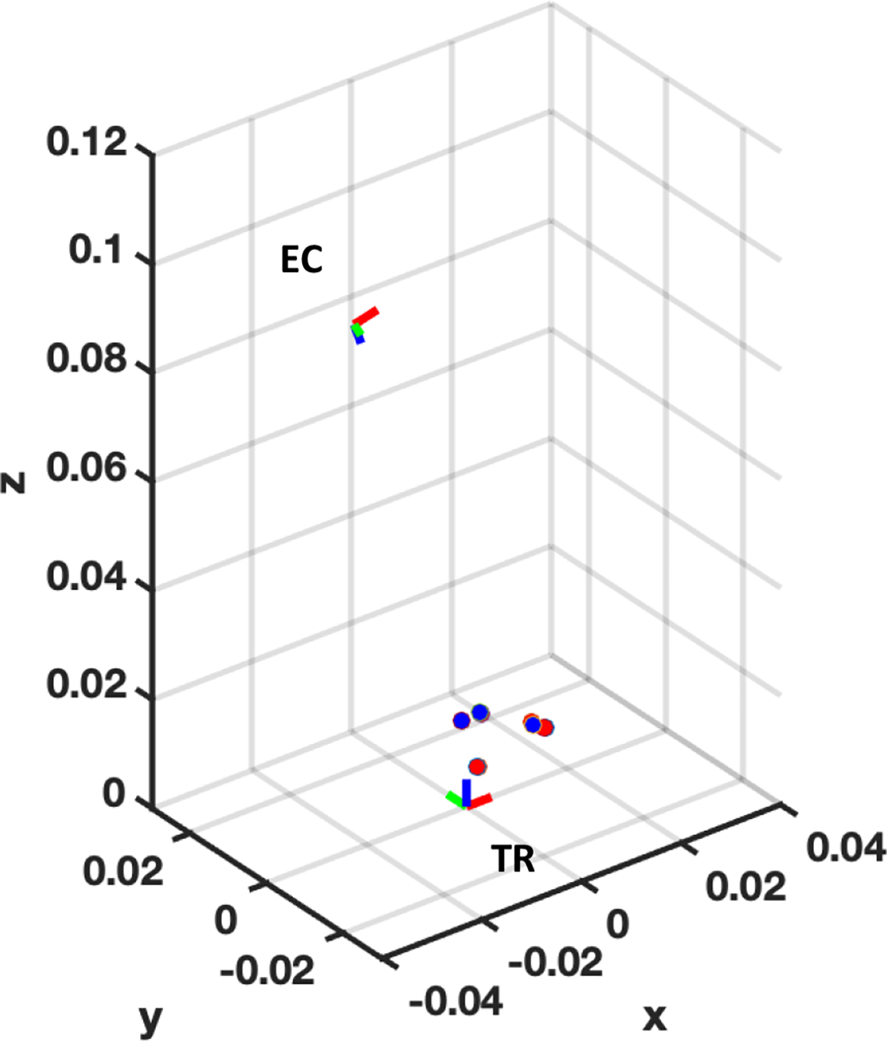
, , axis indicate the lateral, elevational, and axial direction with respect to TRUS coordinate, respectively. Red, green, and blue color of the frame represent , , , direction, respectively.TR: TRUS coordinate frame; EC: Endoscopic camera frame
Table 1.
Quantitative measurement
| Position set | Registration error (mm) |
Tracking error (°) |
||
|---|---|---|---|---|
| Mean | STD. | Mean | STD. | |
| #1 | 0.67 | 0.18 | 1.13 | 0.13 |
| #2 | 1.09 | 0.38 | 1.21 | 0.43 |
| #3 | 0.77 | 0.34 | 1.14 | 0.33 |
Here, further evaluation of the registration performance using PMs was conducted with target registration error (TRE). 15 laser spots were detected by both endoscopic camera and the TRUS transducer as shown in Fig. 9(a, b). Among the 15 point pairs, four pairs were chosen for calculating the transformation, and the rest pairs were used to calculate the TRE. Note that three categories of point pair configurations for transformation calculation were defined based on the distance between the laser spots: (1) Four spots are positioned next to each other, (2) Two spots are positioned next to each other, and two of these are combined to form four points, (3) Four spots are all separated. For example, red, green, and blue squares in Fig. 9(b) indicate the case 1, 2, and 3, respectively. For each case, 10 iterations were conducted to obtain the mean TRE and its standard deviation. The TRE measurement shows that the registration yields better performance when the laser spots are positioned farther away to each other: {2.84±1.12, 2.23±1.07, 1.05±0.37}mm for case 1, 2, and 3, respectively (Fig. 9(c)).
Fig. 9. Evaluation of the configuration of multiple PMs for calculating the transformation.
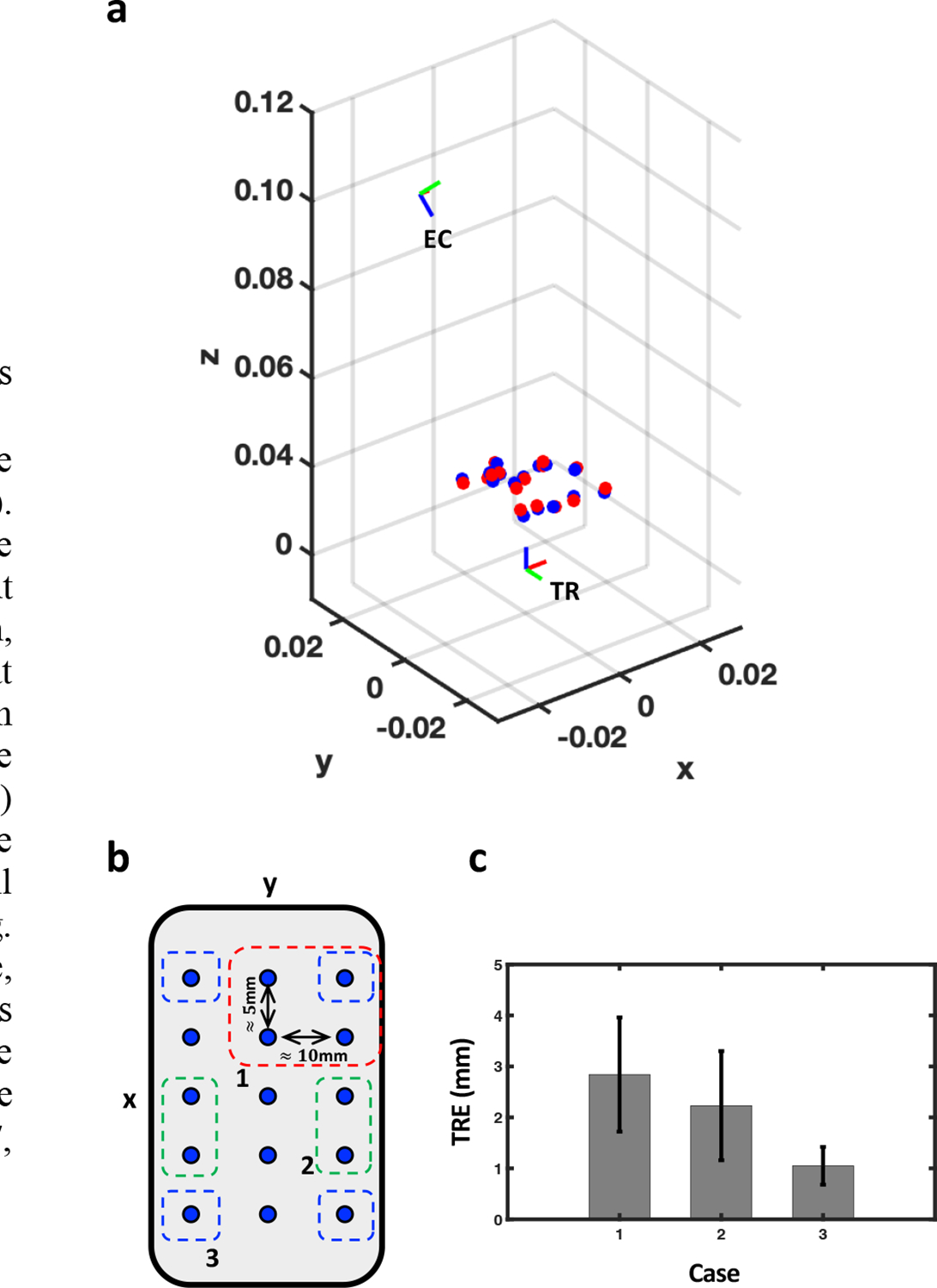
(a) The relative positions of EC and TR, when the TR is at the origin. The red and blue dots represent the PMs detected by the endoscopic camera and the TRUS, respectively. , , axis indicate the lateral, elevational, and axial direction with respect to TRUS coordinate, respectively. (b) x-y plane view of laser spot positions. A 3*5 grid of laser spots are roughly spaced at 5mm and 10mm in and directions, respectively. The red (1), green (2), and blue (3) squares indicate three exemplary cases of point configurations for calculating the transformation matrix. (c) TRE measurements for each case.
IV. Discussion and Conclusion
In this paper, we presented an integrated implementation of a TRUS+PA image-guided intraoperative surgical guidance system based on the PMs. The experiment was performed with a da Vinci surgical robot system which is widely used for RALP procedures. We demonstrated the real-time tracking of PMs by the TRUS transducer in an ex-vivo chicken breast tissue study. The frame registration using PMs was conducted by manually maneuvering the rotation stage, and the resultant registration led to accurate tracking of the PMs. The study does have some limitations that are addressed next and that can be addressed by future work.
First, automatic registration is needed to improve the efficiency in the operating room. Currently, the user is required to manually find the in-plane image that can accurately represent the PM by rotating the actuator. This step will not only be dependent on the user’s subjective opinion or bias, but also requires some time that is not appropriate for conducting before, or during the operation. To improve this, our group is developing a dedicated algorithm (e.g., golden section search algorithm) which will efficiently search for the in-plane angle by incorporating a search algorithm based on the photoacoustic intensity generated from the PM. In addition, automatic registration will also enable online re-calibration during the operation if it is needed. For instance, the position of the endoscopic camera may change based on the surgeon’s intention, where frequent update of the registration matrix is inevitable. Hence, the online re-calibration will allow the system to track the surgical instrument without compromise.
Second, we would need to generate both stronger optical and PA signals from the markers. In our experimental setup, the average power of the laser from the PLD was , which is much lower than what is used in standard photoacoustic imaging. As a result, 250 images were averaged in order to enhance the SNR with imaging up to 2cm in imaging depth. Considering that the distance between the TRUS transducer and PMs in practical scenario is approximately 50 ∼ 60 mm, additional averaging will be inevitable which will further sacrifice the temporal resolution of the PA imaging. Note that the built-in illuminator of the endoscope camera has a maximum output power of 124mW at 805nm wavelength which is much stronger than current PLD setup. Therefore, the laser source with increased power can help resolve the limitation in both PA imaging (i.e., imaging depth and temporal resolution) and further improve FL imaging (i.e., PM detectability).
Third and finally, the actuator needs to be faster. Note that the actuator used in this study was originally manufactured for rotating optical components. The set rotation velocity (i.e., 25°/sec) is slow for continuous tracking of the surgical instrument.
An in-vivo experiment will be performed to evaluate the efficacy of the proposed surgical guidance system. Although this study has shown good results in the ex-vivo setup, there are several challenges when it is applied in surgery. For instance, tissure properties will be different when compared to ex-vivo chicken breast tissue, and this may perturb the PA signals. Also, the presence of blood in the surgical ROI may disturb the visibility of PMs in FL imaging.
The proposed system is not only limited to ICG imaging, but also capable of imaging other types of contrast agents. In particular, FL imaging with a voltage-sensitive-dye (VSD) has recently been proposed by our group to monitor the electrophysiological activity in the cavernous nerves bundles surrounding the prostate in an animal model [21]. Here, the proposed system can be applied with VSD to monitor the active nerve during prostatectomy via PA imaging. We envision that the surgical guidance system can provide the functional information related to nerve activity to the surgeon, ultimately reduce the risk of post-operative complications (e.g., erectile dysfunction) induced by the nerve damage.
Acknowledgments
This work was supported in part by NSF Career Award 1653322, NIH R01-CA134675, the Johns Hopkins University internal funds, Canadian Institutes of Health Research (CIHR), CA Laszlo Chair in Biomedical Engineering held by Professor Salcudean, and an equipment loan from Intuitive Surgical, Inc.
Contributor Information
Hyunwoo Song, Department of Computer Science, Whiting School of Engineering, the Johns Hopkins University, Baltimore, MD 21218 USA.
Hamid Moradi, Department of Electrical and Computer Engineering, the University of British Columbia, Vancouver, BC V6T 1Z4, Canada.
Baichuan Jiang, Department of Computer Science, Whiting School of Engineering, the Johns Hopkins University, Baltimore, MD 21218 USA.
Keshuai Xu, Department of Computer Science, Whiting School of Engineering, the Johns Hopkins University, Baltimore, MD 21218 USA.
Yixuan Wu, Department of Computer Science, Whiting School of Engineering, the Johns Hopkins University, Baltimore, MD 21218 USA.
Russell H. Taylor, Department of Computer Science, Whiting School of Engineering, the Johns Hopkins University, Baltimore, MD 21218 USA.
Anton Deguet, Department of Computer Science, Whiting School of Engineering, the Johns Hopkins University, Baltimore, MD 21218 USA.
Jin U. Kang, Department of Electrical and Computer Engineering, Whiting school of Engineering, the Johns Hopkins University, Baltimore, MD 21211 USA.
Septimiu E. Salcudean, Department of Electrical and Computer Engineering, the University of British Columbia, Vancouver, BC V6T 1Z4, Canada.
Emad M. Boctor, Department of Computer Science, Whiting School of Engineering, the Johns Hopkins University, Baltimore, MD 21218 USA.
References
- [1].Lepor H, “A review of surgical techniques for radical prostatectomy.,” Rev Urology, vol. 7 Suppl 2, pp. S11–7, 2005. [PMC free article] [PubMed] [Google Scholar]
- [2].GUILLONNEAU B and VALLANCIEN G, “LAPAROSCOPIC RADICAL PROSTATECTOMY: THE MONTSOURIS TECHNIQUE,” J Urology, vol. 163, no. 6, pp. 1643–1649, 2000, doi: 10.1016/s0022-5347(05)67512-x. [DOI] [PubMed] [Google Scholar]
- [3].Ficarra V, Cavalleri S, Novara G, Aragona M, Artibani W, and Villers A, “Evidence from Robot-Assisted Laparoscopic Radical Prostatectomy: A Systematic Review,” Eur Urol, vol. 51, no. 1, pp. 45–56, 2007, doi: 10.1016/j.eururo.2006.06.017. [DOI] [PubMed] [Google Scholar]
- [4].Ficarra V et al. , “Retropubic, Laparoscopic, and Robot-Assisted Radical Prostatectomy: A Systematic Review and Cumulative Analysis of Comparative Studies,” Eur Urol, vol. 55, no. 5, pp. 1037–1063, 2009, doi: 10.1016/j.eururo.2009.01.036. [DOI] [PubMed] [Google Scholar]
- [5].Dasgupta P and Kirby RS, “The current status of robot-assisted radical prostatectomy,” Asian J Androl, vol. 11, no. 1, pp. 90–93, 2008, doi: 10.1038/aja.2008.11. [DOI] [PMC free article] [PubMed] [Google Scholar]
- [6].Mitchell CR and Herrell SD, “Image-Guided Surgery and Emerging Molecular Imaging Advances to Complement Minimally Invasive Surgery,” Urol Clin N Am, vol. 41, no. 4, pp. 567–580, 2014, doi: 10.1016/j.ucl.2014.07.011. [DOI] [PubMed] [Google Scholar]
- [7].Sridhar AN et al. , “Image-guided robotic interventions for prostate cancer,” Nat Rev Urol, vol. 10, no. 8, pp. 452–462, 2013, doi: 10.1038/nrurol.2013.129. [DOI] [PubMed] [Google Scholar]
- [8].Raskolnikov D et al. , “The Role of Magnetic Resonance Image Guided Prostate Biopsy in Stratifying Men for Risk of Extracapsular Extension at Radical Prostatectomy,” J Urology, vol. 194, no. 1, pp. 105–111, 2015, doi: 10.1016/j.juro.2015.01.072. [DOI] [PMC free article] [PubMed] [Google Scholar]
- [9].Ukimura O, Magi-Galluzzi C, and Gill IS, “Real-Time Transrectal Ultrasound Guidance During Laparoscopic Radical Prostatectomy: Impact on Surgical Margins,” J Urology, vol. 175, no. 4, pp. 1304–1310, 2006, doi: 10.1016/s0022-5347(05)00688-9. [DOI] [PubMed] [Google Scholar]
- [10].Mohareri O et al. , “Intraoperative Registered Transrectal Ultrasound Guidance for Robot-Assisted Laparoscopic Radical Prostatectomy,” J Urology, vol. 193, no. 1, pp. 302–312, 2015, doi: 10.1016/j.juro.2014.05.124. [DOI] [PubMed] [Google Scholar]
- [11].Long J-A et al. , “Real-Time Robotic Transrectal Ultrasound Navigation During Robotic Radical Prostatectomy: Initial Clinical Experience,” Urology, vol. 80, no. 3, pp. 608–613, 2012, doi: 10.1016/j.urology.2012.02.081. [DOI] [PubMed] [Google Scholar]
- [12].Hung AJ et al. , “Robotic Transrectal Ultrasonography During Robot-Assisted Radical Prostatectomy,” Eur Urol, vol. 62, no. 2, pp. 341–348, 2012, doi: 10.1016/j.eururo.2012.04.032. [DOI] [PubMed] [Google Scholar]
- [13].Bell MAL, Kuo NP, Song DY, Kang JU, and Boctor EM, “In vivo visualization of prostate brachytherapy seeds with photoacoustic imaging,” J Biomed Opt, vol. 19, no. 12, pp. 126011–126011, 2014, doi: 10.1117/1.jbo.19.12.126011. [DOI] [PMC free article] [PubMed] [Google Scholar]
- [14].Zhang HK et al. , “Prostate-specific membrane antigen-targeted photoacoustic imaging of prostate cancer in vivo,” J Biophotonics, vol. 11, no. 9, p. e201800021, 2018, doi: 10.1002/jbio.201800021. [DOI] [PMC free article] [PubMed] [Google Scholar]
- [15].Agarwal A et al. , “Targeted gold nanorod contrast agent for prostate cancer detection by photoacoustic imaging,” J Appl Phys, vol. 102, no. 6, p. 064701, 2007, doi: 10.1063/1.2777127. [DOI] [Google Scholar]
- [16].Moradi H, Tang S, and Salcudean SE, “Toward Intra-Operative Prostate Photoacoustic Imaging: Configuration Evaluation and Implementation Using the da Vinci Research Kit,” Ieee T Med Imaging, vol. 38, no. 1, pp. 57–68, 2019, doi: 10.1109/tmi.2018.2855166. [DOI] [PubMed] [Google Scholar]
- [17].Moradi H, Boctor EM, and Salcudean SE, “Robot-assisted Image Guidance for Prostate Nerve-sparing Surgery,” 2020 Ieee Int Ultrasonics Symposium Ius, vol. 00, pp. 1–3, 2020, doi: 10.1109/ius46767.2020.9251576. [DOI] [Google Scholar]
- [18].Cheng A, Zhang HK, Kang JU, Taylor RH, and Boctor EM, “Localization of subsurface photoacoustic fiducials for intraoperative guidance,” pp. 100541D–100541D–6, 2017, doi: 10.1117/12.2253097. [DOI] [Google Scholar]
- [19].McAuley JH, Farmer SF, Rothwell JC, and Marsden CD, “Common 3 and 10 Hz oscillations modulate human eye and finger movements while they simultaneously track a visual target,” J Physiology, vol. 515, no. 3, pp. 905–917, 1999, doi: 10.1111/j.1469-7793.1999.905ab.x. [DOI] [PMC free article] [PubMed] [Google Scholar]
- [20].Horn BKP, “Closed-form solution of absolute orientation using unit quaternions,” J Opt Soc Am, vol. 4, no. 4, p. 629, 1987, doi: 10.1364/josaa.4.000629. [DOI] [Google Scholar]
- [21].Kang J et al. , “Real-time, functional intra-operative localization of rat cavernous nerve network using near-infrared cyanine voltage-sensitive dye imaging,” Sci Rep-uk, vol. 10, no. 1, p. 6618, 2020, doi: 10.1038/s41598-020-63588-2. [DOI] [PMC free article] [PubMed] [Google Scholar]


