

Abstract
The integration of an ingestible dosage form with sensing, actuation, and drug delivery capabilities can enable a broad range of surgical-free diagnostic and treatment strategies. However, the gastrointestinal (GI) tract is a highly constrained and complex luminal construct that fundamentally limits the size of an ingestible system. Recent advancements in mesoscale magnetic crawlers have demonstrated the ability to effectively traverse complex and confined systems by leveraging magnetic fields to induce contraction and bending-based locomotion. However, the integration of functional components (e.g., electronics) in the proposed ingestible system remains fundamentally challenging. Herein, the creation of a centralized compartment in a magnetic robot by imparting localized flexibility (MR-LF) is demonstrated. The centralized compartment enables MR-LF to be readily integrated with modular functional components and payloads, such as commercial off-the-shelf electronics and medication, while preserving its bidirectionality in an ingestible form factor. The ability of MR-LF to incorporate electronics, perform drug delivery, guide continuum devices such as catheters, and navigate air–water environments in confined lumens is demonstrated. The MR-LF enables functional integration to create a highly-integrated ingestible system that can ultimately address a broad range of unmet clinical needs.
Keywords: ingestible electronics, ingestible robots, soft robots, magnetic robots, magnetic crawlers, drug delivery
Graphical Abstract
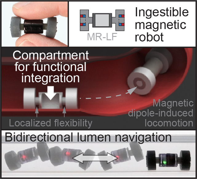
The ability to integrate modular electronics into ingestible magnetic robots can enable a broad range of active functionality. However, the integration of rigid modular components and payloads is challenging. Herein, a centralized compartment is created in a magnetic crawler robot to enhance its functionality while preserving its ingestible form factor and bidirectional locomotion.
1. Introduction
The gastrointestinal (GI) tract plays a crucial role in the human body as a naturally evolved interface between the body and its environment. Ingestible electronics perform surgical-free screenings and diagnoses within the GI tract and have been proposed since 1957.1–4 Recent advancements have demonstrated the ability to integrate ingestible electronics with sensing, actuation, and drug delivery capabilities, with several examples that have been FDA approved and are in clinical use.5–8 For example, the pill-shaped PillCam™ provides access to areas of the GI tract which are challenging or infeasible via endoscopic procedures.8 However, the size of an ingestible device is fundamentally constrained to enable swallowing (e.g., PillCam™ SB 3 has a diameter of 11.4 mm, and a length of 26.2 mm)9 and to mitigate the risks of unexpected retention (1.4% for conventional capsule endoscopes)10 or intestinal obstruction that requires surgical interventions. The limitation in size constrains the possible functionalities that can be integrated into an ingestible system, especially since active components such as microelectronics are rigid and planar parts that have to be assembled into the system. For example, most ingestible electronics do not have the ability to be actively transported toward target regions of interest.8
Indeed, integrating functionalities into ingestible, untethered robots with active locomotion capabilities can enable a broader range of surgical-free diagnostic and treatment strategies.11–15 Earlier research has demonstrated a wide range of locomotion strategies for small-scale robots, including legged,16,17 rolling,18–21 peristaltic (i.e., earthworm-like),22–28 undulatory,29–31 crawling,32–43 and other motions.6,44–47,66–70 Among the demonstrated mechanisms, magnetically controlled actuation is particularly promising because it does not require onboard power or control systems,45 freeing critically needed space for additional functional integration.
Recent advances have demonstrated the ability of miniature magnetic crawlers to actively transport cargo in complex and confined systems, such as the GI tract, by leveraging magnetic fields to induce locomotion. For instance, Zhao et al. demonstrated a magnetic origami robot that crawled by in-plane contraction22 where the anisotropic friction on the robot’s feet enabled forward locomotion that can be steered. Nevertheless, the need for anisotropic friction on the feet also precluded bidirectional locomotion in a confined space, such as in a lumen, where reversing direction by turning in place is challenging. Other recent works demonstrated entirely-soft crawlers with impressive multi-gait bending locomotion that could transport objects by gripping and direct attachment,48–50 including cargos 20 times their mass and three times their volume.48 Nevertheless, integrating the existing crawlers with modular electronics is challenging due to the planar and rigid nature of electronics that will impede the robot’s bending motions.
Other recent works demonstrated axisymmetric crawler robots with flexible bodies and magnetic feet. Importantly, the robots were capable of bidirectional undulatory or inchworm-like locomotion in confined lumens when actuated by an external rotating magnetic dipole.38–40 The nonuniform fields of the actuation mechanism could facilitate clinical use, as utilizing a rotating permanent magnet eliminates the need to surround the patient with coils.39 Nevertheless, the crawler lacked a centralized space necessary for functional integration without disrupting the robot’s locomotion.
Here, we demonstrate a magnetic robot with localized flexibility (MR-LF), which includes a centralized compartment for functional integration. The compartment is created by localizing the body flexibility of a flexible magnetic crawler in the previous work38–40 while preserving the robot’s ingestible size and bidirectional locomotion characteristics. The availability of a centralized compartment enables MR-LF to be readily integrated with modular functional components, such as commercial off-the-shelf electronics, and payloads such as medication. Ultimately, we envision that the integration of sensing, actuation, and drug delivery capabilities into an ingestible robot can address a broad range of unmet clinical needs.
2. Results & Discussion
2.1. Body flexibility
To create an ingestible bidirectional robot with a centralized compartment for functional integration, we build upon the design of recent work by Abbott et al. and Leang et al., where they demonstrated soft endoluminal robots with impressive bidirectional locomotion in confined lumens.38–40 The robots were actuated by a rotating permanent magnet above the robot’s path. The rotating nonuniform (dipole) magnetic field rotates the robot’s feet and flexes the body to generate a periodic gait. The actuator magnet rotation direction dictated the robot locomotion direction.39 However, the magnetic robot in the previous work does not have a centralized compartment for functional integration (hereafter referred to as “magnetic robot with distributed flexibility” [MR-DF]) as its gait motion relies on the flexibility of its entire body.
Here, we create a centralized compartment by localizing the body flexibility of the soft robot and demonstrate the MR-LF design preserves the bidirectional locomotion characteristics and ingestible form factor (Figure 1). Specifically, we modified the robot geometry to localize bending to small regions, or flexures, near each foot to convert the remaining central body length into a compartment for functional integration. We actuate the robot using a cylindrical permanent magnet at a fixed position rotating at an angular velocity ω (Figure 1D). The locomotion of MR-DF was shown to primarily depend on body flexibility and foot rotation induced by the magnetic field of the actuator magnet.40 Thus, to preserve locomotion, the MR-LF flexure geometry was designed to yield the same foot flexion angle as the MR-DF control under an applied torque. The length of the MR-LF flexure was selected as 2 mm to provide sufficient length for bending while preventing contact between the foot and compartment, and the diameter was calculated to be 3.6 mm (details in Experimental Section).
Figure 1:

Actuation and locomotion of MR-LF. (A) A magnetic robot with localized flexibility (MR-LF) navigating through a biological lumen. Rotation of the actuator dipole induces the body bending used for locomotion. (B) Image of fingers holding the fabricated MR-LF. Scale bar: 10 mm. (C) Cross-section illustrations of MR-DF and MR-LF compared to the ingestible PillCam™ SB 3 capsule endoscopy device. MR-DF: magnetic robot with distributed flexibility. (D) Schematic of the experiment setup. A robot in a confined channel is actuated by a rotating actuator magnet at a distance ya relative to the robot’s initial position (x = 0, y = 0). (E) Illustrations (left) and side-view image compositions (right) of an MR-DF (top) and an MR-LF (bottom), both having a mass of 2.55 g. Images demonstrate similar locomotion at ya = 11 cm with time and step number labels and a displacement scale below. (F) Comparison of the initial speed (average speed of the first ten steps) of an MR-DF (black data) with an MR-LF (red data), both having a mass of 2.55 g. Boxes show the 25–75% range, whiskers indicate min-max, and markers indicate mean (n = 5).
The foot flexion of the MR-LF and the MR-DF control was compared using physical half-robot models mounted at a set location (x = 0, ya = 11 cm) in the magnetic field of the actuator magnet. Data of the foot flexion angle across the actuator magnet orientation and images of the maximum and minimum angles are shown in Figure 2. The minimum foot flexion of both models was the same (θf = −21.1°), while the maximum flexion of MR-DF (23.4°) was slightly higher than MR-LF (21.2°). The MR-LF data closely match MR-DF across the entire actuator magnet rotation, which indicates that the methods to localize body flexibility were successful at reducing the bending region length while preserving foot flexion. The slight increase of maximum angle for MR-DF (10%) was expected, as the longer bending length of the MR-DF model caused the foot to be closer to the actuator magnet and thus experience a higher magnetic field strength than the MR-LF model. The difference could also be caused by expected imperfections in the model placement or simplifications in the theoretical calculations, such as neglecting the effect of bending in the material used to join the soft MR-LF flexure and rigid compartment.
Figure 2:

Comparison of body flexibility between the MR-DF and MR-LF designs. (A) Foot flexion angle (θf), as a function of actuator magnet orientation (θa) for half-robots at x = 0, ya = 11 cm. The amplitude of data sets indicates the foot’s flexibility. (B) Images of half-robots at their maximum (left) and minimum (right) foot flexion.
A comparison of small-scale, flexible magnetic robots is included in Table S1 in Supporting Information. In contrast to our work, the prior robots have not leveraged localized flexibility to create a centralized compartment that is capable of enhancing the robot’s functionality without affecting its gait or increasing its form factor.
Here we also note that, consistent with the prior work, an upper limit exists for the body flexibility of MR-DF (which depends on body diameter, body length, and material stiffness) to prevent the robot body from buckling due to the attraction between magnets of the opposite feet.40 Here, by introducing a rigid segment as the compartment that prevents the buckling, the MR-LF design can in principle have a longer body, lower material stiffness, and smaller flexure diameter than MR-DF designs, which could increase robot step size, and hence, speed.40 Additionally, increasing the body length of the MR-LF design could enlarge the compartment and thus increase functionality.
2.2. Robot and compartment size
To evaluate robot and compartment size, the robot’s outer geometry was compared to existing ingestible devices and the compartment was compared to recent work. We report that the geometry changes did not affect the overall size of MR-LF, as the outer diameter (12 mm) and length (25 mm) were the same as the MR-DF control, whose dimensions are based on a robot in previous work.38 These dimensions are comparable to commercial capsule endoscopy devices such as the PillCam™ SB 3 (diameter 11.4 mm, length 26.2 mm)9 and PillCam™ Colon 2 (diameter 11.6 mm, length 32.3 mm),51 suggesting the robot could be feasibly used as an ingestible device at the current scale (Figure 1C). Further scaling down MR-LF is facilitated by the low part count (six total parts), bending-type actuation, and commercial availability of permanent magnets with diameters lower than 1 mm. Additive manufacturing processes could also enable future advances and miniaturization.52–60
Approximately half of previous small-scale, flexible magnetic robots demonstrated cargo transportation capabilities (see Table S1), including impressive reports of robots capable of transporting cargos 20 times the robot body weight and three times the robot volume,48 and more than 100 times robot body weight.61 However, only five identified robots22,34,48,49,62 included an internal compartment. Advantages of a compartment include easier integration and protection in harsh environments.
The MR-LF central compartment has an internal volume of 300 mm3 (length: 7.8 mm, diameter: 7 mm) which comprises 17% of the robot’s volume (1725 mm3). In comparison, most of the prior robots with compartments have smaller compartment-to-robot volume ratios (Table S1). While some previous works have demonstrated a similar order of compartment-to-robot ratio, these demonstrations are limited to the millimeter length scale that is not compatible with the goal of ingestible electronics. For example, a millimeter-scale multigait magnetic robot49 has a compartment volume of 2.5 × 10⁻² mm3, which is 120,000 times smaller than the compartment in MR-LF. Another example leverages a magnetically-actuated cylindrical compartment48 with a compartment-to-robot ratio of ~36% but with a ~500 times smaller volume than MR-LF. In another example, a recent ingestible magnetic origami crawler22 demonstrated a compartment for a cargo volume that is 12.5x smaller than MR-LF (24 mm3, ~7% of robot volume) that is not centralized (3.5% on each robot end) and requires fixed-free mounting to preserve actuation. In summary, in contrast to previous works, MR-LF localized flexibility endows the device with a large (300 mm3) centralized compartment that can be integrated with functional modules (e.g., electronics) within an ingestible form factor (Table S1).
We remark that as the robot gets smaller, the separation distance between the magnets in the robot decreases. A smaller separation distance can decrease the effectiveness of locomotion as it increases interactions between robot magnets and affects the phase shift between the rotation of the robot feet, which enables locomotion in a deterministic direction. While the actuation method is anticipated to remain effective, several design variables of the magnetic and structural design, including the strength of the actuator and robot magnets, material stiffness, and offset distance, would need to be modulated accordingly to maintain dynamic similarity for miniaturization in future studies.
2.3. Effect of geometry on speed
To investigate the effect of localizing flexibility on locomotion speed, experiments were performed using an MR-DF and an MR-LF with an equal mass (2.55 g). In each experiment, the robot was placed in a confined channel and actuated by a rotating actuator magnet at x = 0, y = ya (Figure 1D). The rotation of the actuator magnet about the -z axis induced locomotion in the +x direction due to the phase shift in time-varying torque on the robot feet.38 A range of ya values was studied because existing literature reported a relationship between ya and locomotion.38
Results show that the average initial speed (average speed for the first ten steps of locomotion) of MR-LF was faster than the MR-DF control at every ya offset (Figure 1F). At ya = 11 cm, the robots had the closest speeds (difference of 3%) and exhibited their fastest average initial speed (MR-DF: 6.61 mm/rev, MR-LF: 6.82 mm/rev). The largest difference (299%) and slowest average initial speed for both designs were at ya = 15 cm (MR-DF: 0.34 mm/rev, MR-LF: 1.37 mm/rev). As anticipated, the closeness in robot speeds is likely due to the comparable foot flexion between the designs (0% difference in minimum, 10% difference in maximum foot flexion). The superior performance of MR-LF, which had an average initial speed of 0.21 to 2.27 mm/rev faster than MR-DF across all ya, may be due to an expected difference in mass distribution between the robots or the 10% reduction in maximum foot flexion. The closeness in locomotion performance between the MR-DF and MR-LF designs and the superiority of MR-LF across all ya is exciting because it demonstrates that localizing flexibility yielded a 3–299% increase in speed while also freeing up space for an internal compartment (300 mm3) for functional integration.
In the experiments, the robot’s locomotion away from the actuator magnet was consistent with prior literature40 to demonstrate the feasibility of locomotion against the attraction forces between the robot and actuator. In practice, robot speed and endurance can be improved by having the robot travel toward the actuator magnet and actively modulating the separation between the actuator and robot.
2.4. Effect of robot mass on speed
To investigate how the increased mass of functional components and payloads within the compartment affects locomotion speed, experiments were performed using MR-LF with varying mass (2.55, 2.87, 3.5, and 4.43 g). Comparison between plots shows that, in general, increasing MR-LF mass increases the initial speed at smaller ya values and lowers the initial speed at larger ya values within the studied ya range (Figure 3A). At the smallest offset (ya = 9 cm), the heaviest MR-LF (4.43 g) exhibited the fastest average initial speed (9.01 mm/rev), while the other MR-LFs were unable to exhibit effective locomotion (discussed in the next section). Conversely, at the largest offset (ya = 15 cm), the heaviest MR-LF (4.43 g) exhibited a low average speed (0.02 mm/rev), while the 2.55 g and 2.87 g MR-LFs had average speeds greater than 1.0 mm/rev. The difference in speeds is due to the mass of the robots, as robots with higher mass can resist a higher lift force that is generated by a higher magnetic field strength, which we discuss in detail in Section 2.5.
Figure 3:

Effect of robot mass and actuation distance on locomotion. (A) Initial speed of MR-LF with various masses across ya offsets (box colors). Boxes show the 25–75% range, whiskers indicate min-max and mean values are connected by a black line (n = 5). A comparison between plots shows the effect of mass on speed. (B) Schematic showing total actuation distance (da), calculated as the diagonal distance from the actuator magnet center to the robot center. (C,D) Total actuation distance (da) as a function of step number for the MR-LF (C) and MR-DF (D) designs across ya distances (line color). Trials of ya = 10 to 14 cm converge within a span of da (indicated by brackets and denoted da*) which corresponds to the minimum field strength needed for locomotion.
Our results have also demonstrated that MR-LF achieved locomotion even with a mass greater than existing capsule endoscopy devices (PillCam™ SB 3: 3.0 g, PillCam™ Colon 2: 2.9 g).9,51 Indeed, the heaviest robot in our experiments exhibited the fastest average initial speed (9.01 mm/rev), and results show that increasing robot mass can improve locomotion speed and change the ya for the fastest locomotion. To further investigate this mechanism, we study the effect of magnetic field strength on locomotion as described in the next section.
2.5. Effect of magnetic field strength on locomotion
To investigate how magnetic field strength influences locomotion, we examine the locomotion data represented as total actuation distance (da, Figure 3B) with respect to step number (Figure 3C-D). Representing robot locomotion as da facilitates comparison between robots tested at different ya offsets because robots experience the same time-varying magnetic field strength at the same da. We note that both the strength and direction of the magnetic field vary during actuation due to the rotation of the actuator magnet (magnetic field strength plots in Figure S1).
The data in Figure 3 show that, in general, smaller ya caused an increase in speed due to the higher magnetic field strength and thus stronger actuation at smaller ya until an upper limit where the high magnetic field strength lifts the robot’s feet from the bottom of the lumen for the entire step. As expected from this observation, increasing the robot mass can increase the upper magnetic field strength limit, as shown by the data for MR-LF 4.43 g, which performed the fastest locomotion at ya = 9 cm.
As the field strength approaches the upper limit, a slight perturbation or changes in conditions at this field strength (e.g., inherent variation of motion) can result in a significant variation of the speed as the robot will either produce the largest speed due to the highest field strength, or a near zero speed due to the loss of contact with the bottom of the lumen. The magnetic field strength at ya = 10 cm (10.32 mT, xa = 0, θa = 90°) appears to be near the upper limit for three robots (MR-DF, MR-LF 2.55 g, and MR-LF 2.87 g). Indeed, at ya = 10 cm with the same experimental condition, each of these three robots exhibited effective gait with high speeds in some trials but were lifted and resulted in near zero speed in other trials due to inherent variations in conditions and motion. This significant variation in speeds, which is evident in the ya = 10 data in Figure 3 and S3, caused the large error in the average speed at ya = 10.
From the data in Figure 3C-D, we also observe that after 40 steps, all trials between ya = 10 to 14 cm converge within a span of da (denoted da*). We hypothesize that robots stopped traveling within da* because the time-average field strength of the actuator magnet near the mean of da* was unable to overcome the forces (e.g., friction) impeding locomotion. Further, the mean of the data within da* decreased with increased MR-LF mass (e.g., 2.55 g: 14.37 cm, 4.43 g: 13.22 cm), suggesting that a heavier robot requires a higher magnetic field strength to move. The ya = 9 cm trials for the heaviest MR-LF (4.43 g) also converge within da* because its increased mass enabled it to move at the higher magnetic field strength at ya = 9 cm.
2.6. Gait type
To analyze the locomotion characteristics of MR-DF and MR-LF, the gait type for the first ten steps (five seconds) of each experiment trial was identified and organized in the table in Figure 4A. Gait was classified into five categories: run, walk, crawl, no travel, and inhibited (images during one step of the run, walk, and crawl gaits are shown in Figure 4B). In the “run” gait, both robot feet were simultaneously off the ground at some instances during locomotion; in the “walk” gait, only one foot was off the ground at a time; and in the “crawl” gait, both feet stayed in contact with the ground. If the robot was unable to move more than 10 mm during the 60-second test and remained in contact with the bottom of the lumen, the gait is defined as “no travel.” If the robot was lifted and unable to move due to the lifting forces of the actuator magnet, the gait is defined as “inhibited.” We reported the gait type exhibited during a majority of the first ten steps as, in some cases, the differences between gait types could be subtle. We reported a combination of gait types in cases (e.g., during transition) where the robot exhibited an approximately equal ratio of two gait types.
Figure 4:

MR-DF and MR-LF gait type. (A) Table showing the gait exhibited by robots in their first ten steps as a function of ya (rows) and robot type and mass (columns). Complete descriptions of each gait type are included in the main text. (B) Representative side-view image sequences of data underlined in A during the second step of the 2.55 g MR-DF (left columns) and the 2.55 g MR-LF (right columns) robots for the run, walk, and crawl gaits. The approximate θa and corresponding step percentage are included on the left. The length of the displayed step and the initial speed (average speed for the first ten steps) are labeled below the image sequences. Red vertical lines are aligned with the robot’s leading foot at θa = 0° to show the distance traveled during the step. Scale bars: 10 mm.
The data in Figure 4A show a relationship between gait type and ya. For instance, trials at larger ya (13 to 15 cm) exhibited the “crawl” gait where both feet remain on the ground, and trials at smaller ya (9 to 12 cm) exhibited gaits where feet are lifted off the ground (e.g., run, walk) due to the higher magnetic field strength. Moreover, as the mass of MR-LF increased, a higher magnetic field strength (i.e., smaller ya) was required to produce the same gait type. For instance, at ya = 12 cm, the lightest MR-LF exhibited a “walk” gait, while the heaviest MR-LF exhibited a “crawl” gait. As noted in the previous section, the high magnetic field strength at ya = 9 cm caused all robots except the 4.43 g MR-LF to be lifted to the top of the channel and exhibit an “inhibited” gait. Similarly, the magnetic field strength at ya = 10 cm resulted in an “inhibited” gait during some of the experiments (“IR*” classification applied when effective run gait began after the tenth step). Due to this transition between “run” and “inhibited” gait at high field strengths, the “run” gait may not be as desirable as the “walk” or “crawl” gaits if the goal is to maintain consistent robot locomotion. The gait characteristics and analysis presented here can inform future studies where a particular target gait can be achieved, refined, and tailored for a specific application.
Representative images, shown in Figure 4B, demonstrate the “run,” “walk,” and “crawl” gait types of the MR-DF and the MR-LF of equal mass (2.55 g). A comparison between the images demonstrates that localizing flexibility enabled the creation of a centralized compartment without impeding the robot’s locomotion characteristics (Figure 4B, Movie S1, S2, and S3).
2.7. Functional integration and payload transportation
The ability to integrate modular components and payloads can functionalize ingestible magnetic crawler robots with advanced sensing, actuation, and drug delivery capabilities that can ultimately enable a broad range of surgical-free diagnostic and treatment strategies. Here we show that the centralized compartment in MR-LF enables the integration of modular electronic components (Figure 5A, Movie S4) which are otherwise challenging to integrate into soft robots due to their rigid and planar architectures. The MR-LF compartment also facilitates the incorporation of payloads such as medications for drug delivery (Figure 5C, Movie S5) and can potentially provide storage space for tissue and fluid samples acquired by the robot.63,64 In the experiment shown in Figure 5C and Movie S5, the medication release is triggered by the temperature of the water environment. The compartment in MR-LF readily enables the integration of alternative triggerable release mechanisms63,64 for drug deliver at a specific target location. Further, though not the focus of this study, we also show that multiple robots can be assembled, similar to a previous study by Abbott et al.,38 by conjoining two MR-LFs with feet with opposite polarity. Such capability suggests that the functionality is not limited to a single dosage form, as multiple pills can be taken to further increase functionality and payload (Figure 5B, Movie S6).
Figure 5:

Functional integration and payload transportation with MR-LF. White arrows indicate crawling direction. (A,B) Side-view image compositions of MR-LF bidirectional locomotion in a rigid confined channel (ID: 19 mm) with (A) electronics in its rigid compartment, and (B) as conjoined robots demonstrating that after ingestion, multiple MR-LFs could be assembled and actuated. (C,D) Side-view image sequences of drug delivery with a modified MR-LF and a modified MR-LF-S in a compliant, thin-walled tube (ID: 16 mm, wall thickness: 0.05 mm). Both robots descend into the water (36 °C) and deliver blue dye to simulate drug delivery, then climb back out of the water on a slope (θ = 8°). For remote drug delivery (C), the MR-LF has a perforated compartment containing a dye-filled dissolvable capsule. For catheter tip navigation (D), the soft MR-LF-S compartment is cast around flexible tubing to demonstrate MR-LF-S with an internal lumen being used to guide continuum devices such as catheters and endoscopes. (E,F) Top-view illustrations (left) and angled view images (right) show bidirectional robot locomotion and turning in confined channels (ID: 19 mm). Arrows in illustrations show the trajectory of the robot. In (E), the robot moves through a 180° bend, and in (F) the robot moves through a bifurcation with an angle of 30°. Scale bars: 10 mm.
We also demonstrate that the centralized compartment does not compromise the robot’s bidirectional locomotion in water (Movie S7) and when moving between water and air environments, even on a slope with an angle of 8° (Figure 5C-D, Movie S5, and S8). Bidirectional motion is critically useful in a confined region where reversing direction by turning in place is challenging such as in the lumens of the human body. In addition, the MR-LF design is able to overcome obstacles (Movie S9) and push obstacles in the lateral direction (Movie S10) as may be necessary in confined and complex environments.
We also demonstrate that the MR-LF rigid compartment can be entirely replaced with a soft material (“MR-LF-S”) without a loss of locomotion characteristics (details in Supporting Information). The design of MR-LF-S can incorporate an internal lumen, similar to what was exhibited for an MR-DF design in a previous study.38 Indeed, tethering a continuum device (e.g., catheter) to the MR-LF-S internal lumen can enable novel treatment and diagnosis in a highly-confined region. For instance, MR-LF-S can guide and transport diagnostic tools (e.g., endoscope) or enable local delivery of drugs (Figure 5D, Movie S8). Further, the entirely soft compartment suggests the future possible integration with prior works in 3D printing of soft magnetic materials to create an entirely-soft robot.52,65
Lastly, we demonstrate MR-LF’s ability to navigate turns and bifurcations in confined channels (Figure 5E-F and Movie S11-S12). The turning is achieved by controlling the position and orientation of the actuator magnet in the x-z plane at ya = 11 cm such that the rotation axis is approximately perpendicular to the robot’s path. Importantly, MR-LF is also capable of bidirectional locomotion in a confined lumen where reversing direction by turning in place is challenging. Specifically, as shown in Figure 5E, the robot starts at location 1 and moves forward around the 180° bend. At location 2, the actuator magnet rotation direction is reversed such that the robot reverses direction and moves backward around the bend to location 1. Similarly, in Figure 5F, the robot moves forward from location 1 to 2, backward to location 1, then forward through the other side of the bifurcation to location 3. As demonstrated in the data, the turning and bidirectional locomotion capabilities can be combined to enhance the navigation ability of MR-LF. Indeed, building on these demonstrations, we anticipate that more complicated robot trajectories could be achieved by controlling the actuator magnet’s position, orientation, and rotation direction.
3. Conclusion
The ability to integrate and transport active components such as microelectronics in small-scale robots can impart functionality into an otherwise passive construct. However, conventionally manufactured components such as microelectronics are rigid and planar parts that are challenging to integrate into existing crawler designs without disrupting their intrinsic locomotion. In this study, we demonstrated the creation of a centralized internal compartment for functional integration by localizing the body flexibility of a flexible magnetic crawler. We then showed that the centralized compartment enables MR-LF to be readily integrated with a wide range of modular functional components and payloads, such as commercial off-the-shelf electronics and medication, while preserving its bidirectionality and ingestible form factor. We also showed a soft-bodied design with an internal lumen that can steer a continuum device such as a catheter in an endoluminal construct, for instance, to enable local delivery of drugs or diagnostic tools. Ultimately, we envision that MR-LF can address a broad range of unmet clinical needs by realizing a highly-functional ingestible system.
4. Experimental Section
4.1. Locomotion experiments
In each locomotion experiment, the robot was placed in a clear polycarbonate circular channel (inner diameter [ID]: 19 mm) with the robot center at x = 0, y = 0. For locomotion and bending experiments, the cylindrical actuator magnet (DY0X0-N52, K&J Magnetics) was located at a fixed position (x = 0, y = ya) with the south pole initially pointing in the +x direction. Next, the actuator magnet was rotated by a geared DC motor at a fixed voltage, producing a frequency of 2.0 ± 0.1 Hz with rotation about the -z axis. Consistent with prior literature,40 the direction of robot locomotion is oriented away from the fixed location of the actuator magnet (i.e., away from x = 0) to demonstrate the feasibility of moving against the attraction forces between the robot and actuator. Five trials were performed for each robot across ya offsets from 9 to 15 cm. Displacement was measured by tracking the center of the robot from a video recording of the test (Canon EOS 80D, frame rate: 29.97 fps). Displacement was calculated every 15 frames or approximately one measurement per step. The initial speed was calculated by dividing the total displacement in the first ten steps by the number of steps. For variable-mass experiments, weight was added inside the rigid compartment of MR-LF. Variability in locomotion test results could be due to several factors, including slight variations in robot starting position and magnet rotation frequency and minor fabrication defects. To reduce potential data bias from possible imperfections in the robot’s feet, the channel and robot were rotated about the x-axis between trials so different portions of the foot were in contact with the floor.
4.2. Robot fabrication
Robots were cast in 3D-printed molds (Form3, Formlabs) from addition-cure silicone (Dragon Skin™ 10 Medium, Smooth-On) with pigment (Silc Pig™, Smooth-On) added to aid visualization. Separate molds were used for the MR-DF, MR-LF, and MR-LF-S designs. Before casting, the molds were coated with a release agent. The silicone was mixed at a 1:1 ratio (w/w, parts A:B) in a planetary centrifugal mixer (AR-100, Thinky) for 60 seconds at 2000 rpm, then injected into the molds using a syringe and dispensing tip. After casting, magnets (R422-N52, K&J Magnetics) were glued into cavities in each foot using a silicone adhesive (Sil-Poxy™, Smooth-On) and cured overnight. Magnets were aligned coaxially with opposite polarity (i.e., both north poles pointing out). The two-part rigid compartment in MR-LF was 3D printed (Form3, Formlabs), assembled, and placed into the MR-LF molds before casting. The flexure was joined to the compartment by having silicone from the flexure extend into a cavity at the end of the compartment during casting. The overall length (25 mm), foot diameter (12 mm), and foot length (5 mm) were the same for all robots. The body length and diameter of MR-DF were 15 mm and 5 mm, respectively. The body geometry of MR-LF was as follows: flexible segment length 2 mm, flexible segment diameter 3.6 mm, compartment length 11 mm, and compartment diameter 8 mm. The compartment’s outer diameter was designed to be small enough to prevent undesired contact between the robot body and channel. The MR-LF-S had the same geometry as MR-LF and was fabricated with the methods described above, except the feet, flexures, and compartment were cast as a single unit from the silicone. Half-robot models for body flexibility tests were fabricated using the same methods as described above using half-robot molds. The single magnet was glued (with the north pole out) into the foot, and the midsection face was glued to a custom 3D-printed PLA mount using the silicone adhesive and cured overnight. All full-robot models were fabricated with the same batch of silicone to avoid variation due to material properties. Similarly, all half-robot models were made from the same silicone mixture.
4.3. Body flexibility calculation and experiments
To localize body flexibility, calculations were performed to determine the MR-LF geometry that would yield the same foot flexion as the MR-DF design while limiting the bending in MR-LF to a small region, or flexure, near each foot. The length of the MR-LF flexure was chosen as 2 mm to avoid contact between the foot and compartment, and the diameter was determined using cantilever beam equations. The robots were modeled as a cantilever beam with the midsection fixed and a constant torque applied to the free end, with the assumption that bending was symmetric on both sides of the robot and resulted from a uniform torque applied on the robot foot. For the MR-DF design, bending was assumed to occur across the entire half-body length (7.5 mm), whereas, for the MR-LF design, the compartment was assumed to be rigid so bending only occurred in the MR-LF flexure (length: 2 mm). By setting the maximum bending angle of each case to be equal, the diameter of the MR-LF flexure was calculated to be 3.6 mm.
To evaluate the effect of localized flexibility on the overall body flexibility, experiments were performed using physical half-robot models mounted with the midsection face at x = 0 in the magnetic field created by the actuator magnet (Figure 2B; magnetic field plots in Figure S1). Body flexibility was determined using the maximum and minimum foot flexion angles for the designs. Foot flexion was measured from a video of the half-robot models being actuated through three rotations of the actuator magnet. The θa data in Figure 2 and S2 were adjusted to represent θa during a representative rotation of the actuator magnet.
4.4. Functional integration and payload transportation experiments
To demonstrate functional integration and payload transportation enabled by MR-LF, experiments were performed using procedures similar to the locomotion experiments. To demonstrate bidirectionality, the rotation direction of the actuator magnet was reversed mid-test. Obstacle traversal was demonstrated in a larger channel (ID: 25.4 mm) with an obstruction made from a clear adhesive gel-like putty (Clear Museum Gel, Quakehold!). Obstacle pushing was performed using a robot with a mass of 3 g and a cylindrical PLA obstacle with a mass of 15 g. Untethered drug delivery was demonstrated using food dye in a gelatin capsule that was placed within a perforated rigid compartment of an MR-LF. The demonstration showing catheter navigation was performed by injecting food dye through flexible tubing (TND80–010, Component Supply Co.) that was cast through the center of an MR-LF-S. Water tests were performed at 36 °C and involved robots moving within a thin, flexible plastic tubing (LDPE Poly Tubing, ID: 16 mm, thickness: 0.05 mm) suspended in an open configuration between two supports. For the demonstrations in Figure 5A-D, the actuator magnet was located at a fixed position, and rotation occurred in the +z or -z direction. For the demonstrations in Figure 5E-F, the robot was turned by controlling the position and orientation of the actuator magnet in the x-z plane at ya = 11 cm such that the rotation axis was approximately perpendicular to the robot’s path.
Supplementary Material
Acknowledgements
Professor Yong Lin Kong acknowledged the support from the 3M Non-Tenured Faculty Award; National Institutes of Health (NIH) NIBIB Trailblazer Award (Grant No. 1-R21-EB029563-01); NIH R01 (Grant No. R01EB032959) and the Utah NASA Space Grant Consortium Faculty Research Seed Funding Awards. Professor Yong Lin Kong and Professor On Shun Pak acknowledged the support from the National Science Foundation (NSF) under Emerging Frontiers in Research and Innovation (EFRI) Program (Grant No. EFRI 1830958).
Supporting Information
Supporting Information is available from the Wiley Online Library or from the author.
Contributor Information
Taylor E. Greenwood, Department of Mechanical Engineering, University of Utah, Salt Lake City, UT 84112 (USA)
Henry Cagle, Department of Mechanical Engineering, University of Utah, Salt Lake City, UT 84112 (USA).
Benson Pulver, Department of Mechanical Engineering, University of Utah, Salt Lake City, UT 84112 (USA).
Prof. On Shun Pak, Department of Mechanical Engineering, Santa Clara University, Santa Clara, CA 95053 (USA)
Prof. Yong Lin Kong, Department of Mechanical Engineering, University of Utah, Salt Lake City, UT 84112 (USA)
References
- 1.Watson BW, Ross B & Kay AW Telemetering from within the body using a pressure-sensitive radio pill. Gut 3, 181–186 (1962). [DOI] [PMC free article] [PubMed] [Google Scholar]
- 2.Mackay RS & Jacobson B Endoradiosonde. Nature 179, 1239–1240 (1957). [DOI] [PubMed] [Google Scholar]
- 3.Jacobson B & Mackay RS, A pH-endoradiosonde. The Lancet 269, 1224 (1957). doi: 10.1016/S0140-6736(57)91792-0 [DOI] [PubMed] [Google Scholar]
- 4.Farrar JT, Zworykin VK & Baum J Pressure-sensitive telemetering capsule for study of gastrointestinal motility. Science 126, 975–976 (1957). doi: 10.1126/science.126.3280.975 [DOI] [PubMed] [Google Scholar]
- 5.Mandsberg NK, Christfort JF, Kamguyan K, Boisen A & Srivastava SK Orally ingestible medical devices for gut engineering. Adv. Drug Deliv. Rev. 165–166, 142–154 (2020). [DOI] [PMC free article] [PubMed] [Google Scholar]
- 6.Basar MR, Malek F, Juni KM, Idris MS & Saleh MIM . Ingestible wireless capsule technology: A review of development and future indication. Int. J. Antennas Propag. 2012, (2012). [Google Scholar]
- 7.Toennies JL, Tortora G, Simi M, Valdastri P & Webster RJ Swallowable medical devices for diagnosis and surgery: The state of the art. Proc. Inst. Mech. Eng. Part C J. Mech. Eng. Sci. 224, 1397–1414 (2010). [Google Scholar]
- 8.Min J, Yang Y, Wu Z & Gao W Robotics in the gut. Adv. Ther 3, 1900125 (2020). doi: 10.1002/adtp.201900125 [DOI] [Google Scholar]
- 9.Medtronic. PILLCAM™ SB 3 SYSTEM. Available at: https://www.medtronic.com/covidien/en-us/products/capsule-endoscopy/pillcam-sb-3-system.html. (Accessed: 31st May 2022)
- 10.Li F, Gurudu SR, De Petris G, Sharma VK, Shiff AD, Heigh RI, Fleischer DE, Post J, Erickson P & Leighton JA Retention of the capsule endoscope: a single-center experience of 1000 capsule endoscopy procedures. Gastrointest. Endosc 68, 174–180 (2008). doi: 10.1016/j.gie.2008.02.037 [DOI] [PubMed] [Google Scholar]
- 11.Sitti M, Ceylan H, Hu W, Giltinan J, Turan M, Yim S & Diller E Biomedical applications of untethered mobile milli/microrobots. Proc. IEEE 103, 205–224 (2015). doi: 10.1109/JPROC.2014.2385105 [DOI] [PMC free article] [PubMed] [Google Scholar]
- 12.Abramson A, Dellal D, Kong YL, Zhou J, Gao Y, Collins J, Tamang S, Wainer J, McManus R, Hayward A, Frederiksen MR, Water JJ, Jensen B, Roxhed N, Langer R & Traverso G Ingestible transiently anchoring electronics for microstimulation and conductive signaling. Sci. Adv 6, eaaz0127 (2020). doi: 10.1109/JPROC.2014.2385105 [DOI] [PMC free article] [PubMed] [Google Scholar]
- 13.Nadeau P El-Damak D, Glettig D, Kong YL, Mo S, Cleveland C, Booth L, Roxhed N, Langer R, Chandrakasan AP & Traverso G Prolonged energy harvesting for ingestible devices. Nat. Biomed. Eng 1, 0022 (2017). doi: 10.1038/s41551-016-0022 [DOI] [PMC free article] [PubMed] [Google Scholar]
- 14.Kong YL & Traverso G Transmitting location. Nat. Biomed. Eng. 1, 684–685 (2017). [DOI] [PubMed] [Google Scholar]
- 15.Kong YL Transforming military medicine with 3D printed bioelectronics. J. Homel. Def. Secur. Inf. Anal. Cent 6, 34–38 (2019). [Google Scholar]
- 16.Quirini M, Menciassi A, Scapellato S, Stefanini C & Dario P Design and fabrication of a motor legged capsule for the active exploration of the gastrointestinal tract. IEEE/ASME Trans. Mechatronics 13, 169–179 (2008). [Google Scholar]
- 17.Xu T, Zhang J, Salehizadeh M, Onaizah O & Diller E Millimeter-scale flexible robots with programmable three-dimensional magnetization and motions. Sci. Robot 4, eaav4494 (2019). [DOI] [PubMed] [Google Scholar]
- 18.Formosa GA, Prendergast JM, Edmundowicz SA & Rentschler ME Novel optimization-based design and surgical evaluation of a treaded robotic capsule colonoscope. IEEE Trans. Robot 36, 545–552 (2020). doi: 10.1109/TRO.2019.2949466 [DOI] [Google Scholar]
- 19.Miyashita S, Guitron S, Yoshida K, Li S, Damian DD & Rus D Ingestible, controllable, and degradable origami robot for patching stomach wounds. Proc. IEEE Int. Conf. Robot. Autom 909–916 (2016). doi: 10.1109/ICRA.2016.7487222 [DOI] [Google Scholar]
- 20.D’Argentre ADP, Perry S, Iwata Y, Iwasaki H, Iwase E, Fabozzo A, Will I, Rus D, Damian DD & Miyashita S Programmable medicine: autonomous, ingestible, deployable hydrogel patch and plug for stomach ulcer therapy. Proc. IEEE Int. Conf. Robot. Autom 1511–1518 (2018). doi: 10.1109/ICRA.2018.8460615 [DOI] [Google Scholar]
- 21.Yim S & Sitti M Design and rolling locomotion of a magnetically actuated soft capsule endoscope. IEEE Trans. Robot. 28, 183–194 (2012). [DOI] [PMC free article] [PubMed] [Google Scholar]
- 22.Ze Q, Wu S, Nishikawa J, Dai J, Sun Y, Leanza S, Zemelka C, Novelino LS, Paulino GH & Zhao RR, Soft robotic origami crawler. Sci. Adv 8, eabm7834(2022). doi: 10.1126/sciadv.abm7834 [DOI] [PMC free article] [PubMed] [Google Scholar]
- 23.Wang K, Ge Y & Jin X A micro soft robot using inner air transferring for colonoscopy. 2013 IEEE Int. Conf. Robot. Biomimetics , ROBIO 2013 1556–1561 (2013). doi: 10.1109/ROBIO.2013.6739688 [DOI] [Google Scholar]
- 24.Heung H, Chiu PWY & Li Z Design and prototyping of a soft earthworm-like robot targeted for GI tract inspection. 2016 IEEE Int. Conf. Robot. Biomimetics , ROBIO 2016 497–502 (2016). doi: 10.1109/ROBIO.2016.7866371 [DOI] [Google Scholar]
- 25.Phee L, Menciassi A, Gorini S, Pernorio G, Arena A & Dario P An innovative locomotion principle for minirobots moving in the gastrointestinal tract. Proc. IEEE Int. Conf. Robot. Autom 2, 1125–1130 (2002). doi: 10.1109/ROBOT.2002.1014694 [DOI] [Google Scholar]
- 26.Rafsanjani A, Zhang Y, Liu B, Rubinstein SM & Bertoldi K Kirigami skins make a simple soft actuator crawl. Sci. Robot 3, eaar7555 (2018). doi: 10.1126/scirobotics.aar7555 [DOI] [PubMed] [Google Scholar]
- 27.Onal CD, Wood RJ & Rus D An origami-inspired approach to worm robots. IEEE/ASME Trans. Mechatronics 18, 430–438 (2013). [Google Scholar]
- 28.Wang W, Yan G, Han D, Meng Y & Pu P Design and testing of a novel gastrointestinal microrobot. Biomed. Microdevices 22, 1–11 (2020). [DOI] [PubMed] [Google Scholar]
- 29.Gilbertson MD, McDonald G, Korinek G, Van De Ven JD & Kowalewski TM Serially actuated locomotion for soft robots in tube-like environments. IEEE Robot. Autom. Lett 2, 1140–1147 (2017). doi: 10.1109/LRA.2017.2662060 [DOI] [Google Scholar]
- 30.Rogóż M, Zeng H, Xuan C, Wiersma DS & Wasylczyk P Light-driven soft robot mimics caterpillar locomotion in natural scale. Adv. Opt. Mater 4, 1689–1694 (2016). doi: 10.1002/adom.201600503 [DOI] [Google Scholar]
- 31.Xin W, Pan FT, Li Y, Chiu PWY & Li Z A Novel biomimic soft snail robot aiming for gastrointestinal (GI) tract inspection. Proc. IEEE RAS EMBS Int. Conf. Biomed. Robot. Biomechatronics 1049–1054 (2020). doi: 10.1109/BioRob49111.2020.9224300 [DOI] [Google Scholar]
- 32.Kim SH, Hashi S & Ishiyama K Hybrid magnetic mechanism for active locomotion based on inchworm motion. Smart Mater. Struct. 22, (2013). [Google Scholar]
- 33.Joyee EB & Pan Y A fully three-dimensional printed inchworm-inspired soft robot with magnetic actuation. Soft Robot. 6, 333–345 (2019). [DOI] [PubMed] [Google Scholar]
- 34.Joyee EB & Pan Y Multi-material additive manufacturing of functional soft robot. Procedia Manuf. 34, 566–573 (2019). [Google Scholar]
- 35.Koh J-S & Cho K-J Omega-shaped inchworm-inspired crawling robot with large-index-and-pitch (LIP) SMA spring actuators. IEEE/ASME Trans. Mechatronicsme 18, 419 (2013). doi: 10.1109/TMECH.2012.2211033 [DOI] [Google Scholar]
- 36.Li T, Zou Z, Mao G, Yang X, Liang Y, Li C, Qu S, Suo Z & Yang W Agile and resilient insect-scale robot. Soft Robot 6, 133–141 (2019). doi: 10.1089/soro.2018.0053 [DOI] [PubMed] [Google Scholar]
- 37.Wu Y, Yim JK, Liang J, Shao Z, Qi M, Zhong J, Luo Z, Yan X, Zhang M, Wang X & Fearing RS. Insect-scale fast moving and ultrarobust soft robot. Sci. Robot 4, (2019). doi: 10.1126/scirobotics.aax1594 [DOI] [PubMed] [Google Scholar]
- 38.Pham LN, Steiner JA, Leang KK & Abbott JJ Soft endoluminal robots propelled by rotating magnetic dipole fields. IEEE Trans. Med. Robot. Bionics 2, 598–607 (2020). doi: 10.1109/TMRB.2020.3027871 [DOI] [Google Scholar]
- 39.Pham LN & Abbott JJ A soft robot to navigate the lumens of the body using undulatory locomotion generated by a rotating magnetic dipole field. IEEE Int. Conf. Intell. Robot. Syst 1783–1788 (2018). doi: 10.1109/IROS.2018.8594247 [DOI] [Google Scholar]
- 40.Steiner JA, Pham LN, Abbott JJ & Leang KK Modeling and analysis of a soft endoluminal inchworm robot propelled by a rotating magnetic dipole field. J. Mech. Robot 14, 051002 (2022). doi: 10.1115/1.4053114 [DOI] [Google Scholar]
- 41.Steiner JA, Hussain OA, Pham LN, Abbott JJ & Leang KK, Toward magneto-electroactive endoluminal soft (MEESo) robots. in ASME 2019 Dynamic Systems and Control Conference, ASME, New York, NY: pp. 1–9 (2019). doi: 10.1115/DSCC2019-9029 [DOI] [Google Scholar]
- 42.Bhattacharjee A, Rogowski LW, Zhang X & Kim MJ Untethered soft millirobot with magnetic actuation. Proc. IEEE Int. Conf. Robot. Autom 3792–3798 (2020). doi: 10.1109/ICRA40945.2020.9197202 [DOI]
- 43.Elder B, Zou Z, Ghosh S, Silverberg O, Greenwood TE, Demir E, Su VS, Pak OS & Kong YL A 3D-printed self-learning three-linked-sphere robot for autonomous confined-space navigation. Adv. Intell. Syst 3, 2100039 (2021). doi: 10.1002/aisy.202100039 [DOI] [PMC free article] [PubMed] [Google Scholar]
- 44.Ng CSX, Tan MWM, Xu C, Yang Z, Lee PS, Lum GZ, Locomotion of miniature soft robots. Adv. Mater 33, 2003558 (2021). doi: 10.1002/adma.202003558 [DOI] [PubMed] [Google Scholar]
- 45.Nelson BJ, Kaliakatsos IK & Abbott JJ Microrobots for minimally invasive medicine. Annual Review of Biomedical Engineering 12, 55–85 (2010). [DOI] [PubMed] [Google Scholar]
- 46.Venkiteswaran VK, Samaniego LFP, Sikorski J & Misra S Bio-inspired terrestrial motion of magnetic soft millirobots. IEEE Robot. Autom. Lett. 4, 1753–1759 (2019). [Google Scholar]
- 47.Runciman M, Darzi A & Mylonas GP Soft Robotics in Minimally Invasive Surgery. Soft Robot. 6, 423–443 (2019). [DOI] [PMC free article] [PubMed] [Google Scholar]
- 48.Wu Y, Dong X, Kim J, Wang C & Sitti M, Wireless soft millirobots for climbing three-dimensional surfaces in confined spaces. Sci. Adv 8, eabn3431 (2022). doi: 10.1126/sciadv.abn3431 [DOI] [PMC free article] [PubMed] [Google Scholar]
- 49.Hu W, Lum GZ, Mastrangeli M & Sitti M Small-scale soft-bodied robot with multimodal locomotion. Nature 554, 81–85 (2018). [DOI] [PubMed] [Google Scholar]
- 50.Xu C, Yang Z, Tan SWK, Li J & Lum GZ Magnetic miniature actuators with six-degrees-of-freedom multimodal soft-bodied locomotion. Adv. Intell. Syst 4, 2100259 (2022). doi: 10.1002/aisy.202100259 [DOI] [Google Scholar]
- 51.Medtronic. PILLCAM™ COLON 2 SYSTEM. Available at: https://www.medtronic.com/covidien/en-us/products/capsule-endoscopy/pillcam-colon-2-system.html. (Accessed: 31st May 2022)
- 52.Kim Y, Yuk H, Zhao R, Chester SA & Zhao X Printing ferromagnetic domains for untethered fast-transforming soft materials. Nature 558, 274–279 (2018). doi: 10.1038/s41586-018-0185-0 [DOI] [PubMed] [Google Scholar]
- 53.Hales S, Tokita E, Neupane R, Ghosh U, Elder B, Wirthlin D & Kong YL 3D printed nanomaterial-based electronic, biomedical, and bioelectronic devices. Nanotechnology 31, 172001 (2020). doi: 10.1088/1361-6528/ab5f29 [DOI] [PubMed] [Google Scholar]
- 54.Greenwood TE, Hatch SE, Colton MB & Thomson SL 3D printing low-stiffness silicone within a curable support matrix. Addit. Manuf. 37, 101681 (2021). [DOI] [PMC free article] [PubMed] [Google Scholar]
- 55.Elder B, Neupane R, Tokita E, Ghosh U, Hales S, Kong YL Nanomaterial patterning in 3D printing. Adv. Mater 32, 1907142 (2020). doi: 10.1002/adma.201907142 [DOI] [PubMed] [Google Scholar]
- 56.McAlpine MC & Kong YL, 3D Printed Active Electronic Materials and Devices, Princeton University, US9887356B2 (2016). [Google Scholar]
- 57.McAlpine MC, Sebastian-Mannoor M, Kong YL & Johnson BN Multi-Functional Hybrid Devices/Structures Using 3D Printing, Princeton University, US9517128B2 (2016). [Google Scholar]
- 58.Ghosh U, Ning S, Wang Y & Kong YL Addressing unmet clinical needs with 3D printing technologies. Adv. Healthc. Mater 7, 1800417 (2018). doi: 10.1002/adhm.201800417 [DOI] [PubMed] [Google Scholar]
- 59.Kong YL, Gupta MK, Johnson BN & McAlpine MC 3D printed bionic nanodevices. Nano Today 11, 330–350 (2016). [DOI] [PMC free article] [PubMed] [Google Scholar]
- 60.Kong YL, Tamargo IA, Kim H, Johnson BN, Gupta MK, Koh TW, Chin HA, Steingart DA, Rand BP & McAlpine MC 3D printed quantum dot light-emitting diodes. Nano Lett 14, 7017–7023 (2014). doi: 10.1021/nl5033292 [DOI] [PubMed] [Google Scholar]
- 61.Lu H, Zhang M, Yang Y, Huang Q, Fukuda T, Wang Z & Shen Y, A bioinspired multilegged soft millirobot that functions in both dry and wet conditions. Nat. Commun 9, 3994 (2018). doi: 10.1038/s41467-018-06491-9 [DOI] [PMC free article] [PubMed] [Google Scholar]
- 62.Ze Q, Wu S, Dai J, Leanza S, Ikeda G, Yang PC, Iaccarino G & Zhao RR Spinning-enabled wireless amphibious origami millirobot. Nat. Commun 13, 3118 (2022). doi: 10.1038/s41467-022-30802-w [DOI] [PMC free article] [PubMed] [Google Scholar]
- 63.Kong YL, Zou X, McCandler CA, Kirtane AR, Ning S, Zhou J, Abid A, Jafari M, Rogner J, Minahan D, Collins JE, McDonnell S, Cleveland C, Bensel T, Tamang S, Arrick G, Gimbel A, Hua T, Ghosh U, Soares V, Wang N, Wahane A, Hayward A, Zhang S, Smith BR, Langer R & Traverso G 3D-printed gastric resident electronics. Adv. Mater. Technol 4, 1800490 (2019). doi: 10.1002/admt.201800490 [DOI] [PMC free article] [PubMed] [Google Scholar]
- 64.Timko BP, Dvir T & Kohane DS Remotely triggerable drug delivery systems. Adv. Mater. 22, 4925–4943 (2010). [DOI] [PubMed] [Google Scholar]
- 65.Wu S, Hu W, Ze Q, Sitti M & Zhao R Multifunctional magnetic soft composites: A review. Multifunct. Mater 3, 042003 (2020). doi: 10.1088/2399-7532/abcb0c [DOI] [PMC free article] [PubMed] [Google Scholar]
- 66.Diller E, Zhuang J, Zhan Lum G, Edwards MR & Sitti M Continuously distributed magnetization profile for millimeter-scale elastomeric undulatory swimming. Appl. Phys. Lett 104, 174101 (2014). doi: 10.1063/1.4874306 [DOI] [Google Scholar]
- 67.Ren Z, Zhang R, Soon RH, Liu Z, Hu W, Onck PR & Sitti M Soft-bodied adaptive multimodal locomotion strategies in fluid-filled confined spaces. Sci. Adv 7, eabh2022 (2021). doi: 10.1126/sciadv.abh2022 [DOI] [PMC free article] [PubMed] [Google Scholar]
- 68.Du X, Cui H, Xu T, Huang C, Wang Y, Zhao Q, Xu Y & Wu X Reconfiguration, camouflage, and color-shifting for bioinspired adaptive hydrogel-based millirobots. Adv. Funct. Mater 30, 1909202 (2020). doi: 10.1002/adfm.201909202 [DOI] [Google Scholar]
- 69.Kim SH, Hashi S & Ishiyama K Magnetic actuation based snake-like mechanism and locomotion driven by rotating magnetic field. IEEE Trans. Magn. 47, 3244–3247 (2011). [Google Scholar]
- 70.Nam J, Jang GH, Jeon SM, Choi K, Development of a crawling microrobot with high steering capability and high stability to navigate through a sharply bent tubular environment. IEEE Trans. Magn 50, 8500704 (2014). doi: 10.1109/TMAG.2014.2324589 [DOI] [Google Scholar]
Associated Data
This section collects any data citations, data availability statements, or supplementary materials included in this article.