

Abstract
Annual bacterial plankton dynamics at several depths and locations in the Baltic Sea were studied by image analysis. Individual bacteria were classified by using an artificial neural network which also effectively identified nonbacterial objects. Cell counts and frequencies of dividing cells were determined, and the data obtained agreed well with visual observations and previously published values. Cell volumes were measured accurately by comparison with bead standards. The survey included 690 images from a total of 138 samples. Each image contained approximately 200 bacteria. The images were analyzed automatically at a rate of 100 images per h. Bacterial abundance exhibited coherent patterns with time and depth, and there were distinct subsurface peaks in the summer months. Four distinct morphological classes were resolved by the image analyzer, and the dynamics of each could be visualized. The bacterial growth rates estimated from frequencies of dividing cells were different from the bacterial growth rates estimated by the thymidine incorporation method. With minor modifications, the image analysis technique described here can be used to analyze other planktonic classes.
A standard procedure used to determine concentrations and biovolumes of microorganisms in studies of the population dynamics of natural aquatic communities is microscopic examination of filtered fluorescently dyed cells (10, 14, 19). Counting and measuring individual cells are normally done visually, which is tedious and time-consuming. It is possible to automate the procedure as follows: (i) the microscope image is digitized with a camera and digital frame grabber, (ii) the image is processed to distinguish objects from the background, and (iii) parameters and features of individual objects are analyzed. For the most part these tasks have been studied individually by workers in different disciplines. Complete automation of sample filtration and microscope loading has not been achieved, but image analysis can be fully automated simply and cheaply (17). Below, we describe a combination of methods which can be used for versatile, efficient processing of many images in order to obtain reliable, high-resolution data on aquatic plankton dynamics, particularly the dynamics of the bacterial fraction. The 1995 annual dynamics of bacterial plankton samples obtained at three stations in the Gulf of Bothnia at multiple depths were used in this study for purposes of analysis and illustration.
Camera and microscope.
Charged coupled device (CCD) cameras are the best choice for photometric applications. However, the exposure times under epifluorescence conditions at high magnifications are around 1 s and thus are much longer than the maximum exposure time of standard video cameras (1/25 s). Many manufacturers produce special cameras which allow integration of light over long exposure times, resulting in high image quality and low noise. Typically, these cameras display images in standard video resolution (ca. 700 by 500 pixels) from a frame buffer. Their control boxes often have a built-in frame grabber for transferring digital images to a computer. There are economic advantages in being compatible with standard video cameras, but the small image matrix limits the field of view and the number of gray levels used to render the image (dynamic range) is usually limited to 256. Cameras with larger image matrixes (e.g., 1,000 by 1,300 pixels) are available. These cameras are expensive but usually offer a high dynamic range in addition to a large field of view. This can be important for capturing faint details, such as flagella, without overexposing cell bodies.
The resolution of an optical system can be defined as the ability to discern spatial frequencies (25). The minimum distance (dres) between two lines that can be resolved at a wavelength of λ with a microscope objective having a numerical aperture of N is (25):
 |
1 |
Full use of the resolution of the optics occurs when the pixel size in the resulting digital image is less than 0.5dres. A typical setup is λ = 0.5 μm and N = 1.3, which results in 0.5dres = 0.048 μm. A CCD with a pixel size of 12 μm requires a magnification of about ×250 (12 μm/0.048 μm) for maximum feature definition. In practice, feature definition can be compromised for a larger field of view by lowering the magnification somewhat.
Identification of objects.
The limited resolution of microscope optics results in blurred edges of objects when they are viewed at high magnification (see above). In addition, uneven lighting and differences in exposure times and object luminescence make it impossible to choose a single gray level as a threshold for distinguishing objects from the background. Viles and Sieracki (27) discussed this problem with respect to bacteria under epifluorescence conditions and concluded that a Marr-Hildreth operator (16) functions with a high degree of independence for exposure and lighting characteristics and with accurate edge detection properties. A Marr-Hildreth operator is a combination of a Gaussian operator for smoothing and a Laplace operator for amplifying high spatial frequencies. The Laplace operator calculates the second derivative of intensity. If the edge of a blurred object is at the point where the rate of intensity change is greatest (second derivative), the Laplace operator identifies its position as the zero crossing between positive and negative values. This seems logical and is appealing, because it is suspected that basic animal vision functions in somewhat the same way (16) and virtually the whole problem of edge detection is solved with only two operations (i.e., applying the Marr-Hildreth filter and thresholding to a constant value). However, the Laplace operator is sensitive to electronic camera noise (17) and to faint particles, which can be a problem for analysis of, for example, soil smears (3).
Classification of objects.
Classification of objects has been elegantly accomplished to a remarkable degree with animal vision, and trying to mimic this process in machine vision is an obvious goal. One tool which can be used for this is an artificial neural network. An artificial neural network can be thought of as a complex function that can be programmed to give a certain output configuration in response to a certain input configuration. This is thought to be the means by which true neural networks work in a nervous system, and the procedure of programming an artificial neural network is called “training.” The ability of an artificial network to learn can be measured by its ability to generalize beyond the examples that it is given during the training procedure. The use of a network for classification is attractive because the decision concerning which components of the definition are most important for classification is made automatically. In order for the network to perceive an object, it must be supplied with a definition of shape. The raw image data contains too many degrees of freedom for a simple definition. It is an advantage to have a definition which has a constant number of parameters in order to simplify the shape and which is rotation independent. The best way to accomplish this is to use the Fourier transform, which converts spatial data in the form of coordinate pairs or intensity matrixes into spatial amplitudes, frequencies, and phases. This separates information related to rotation, intricacy of detail, and position. Simpson et al. (22) and Culverhouse et al. (4) used a subset of the power spectrum of the two-dimensional Fourier transform with binarized images to define certain phytoplankton and protozoans. Svarer (26) used an elliptic Fourier transform in which each pixel coordinate pair in the object contour was a complex number. The two approaches are similar, but the latter is faster, and the simplified shape of each object can be reconstructed with the inverse transform and can be plotted to give a view of how the network classifier perceives the object definition. Contour definitions, however, have limitations. A more sophisticated definition is required for species which are identified by color or texture, but the approach could be considered the first step in a multilevel procedure for achieving a good description. Sophisticated staining procedures help segregate major classes into, for example, DNA-containing organisms, heterotrophs, autotrophs, and detritus (20, 28, 29), especially in conjunction with a bandpass filter (27). Confocal microscopy can improve contrast and resolution by eliminating light from objects which are out of focus, and this technique works well with specific staining for highlighting objects of interest (e.g., bacteria) (3).
Growth rates.
The frequency of dividing cells (FDC) in a microbial community reflects the growth rate (12). Frequencies corresponding to bacterial growth rates in situ are often only a few percent, which makes the method particularly attractive when a large number of individuals can be processed. It has been demonstrated that accurate FDC measurements can be acquired by image analysis (3).
MATERIALS AND METHODS
Samples and preparation.
In 1995, water samples were collected in the Gulf of Bothnia as part of a Swedish national environmental monitoring program. Samples were collected six times (weeks 2, 20, 26, 32, 36, and 48) during the year at the following three stations: F9 (subarctic, off-shore; 64°42.5′N, 22°04.0′E), US5 (off-shore; 62°35.0′N, 19°58.5′E), and NB1 (coastal; 63°30.5′N, 19°48.0′E). Samples were obtained from five to nine depths at each station. The samples were fixed in formalin and stored at 5°C. The analysis was performed in September 1996. In order to visualize bacteria, 4- to 10-ml samples were stained with acridine orange and filtered onto black, 0.2-μm-pore-size Nuclepore filters (14). The filters were then briefly allowed to dry at room temperature, immersed in paraffin oil on microscope slides, and covered with coverslips.
Image acquisition.
A Hamamatsu model C4742 black and white digital camera (1,000 by 1,018 pixels; pixel size, 12 μm; 10-bit dynamic range; 1,024 gray levels) was mounted on a Zeiss Axiovert 100 epifluorescence microscope equipped with a Plan Neofluar 100x/1.3 oil immersion objective. The pixel size in the resulting image was 0.12 μm square. The exposure times were approximately 0.33 s. Images were acquired from the camera with an Imagequest IQ-D100 digital frame grabber (Hamamatsu) housed in a Power Macintosh 7100/66 computer. The frame grabber’s application program, IQBase, was used to view images on the computer screen for focusing, capturing, and saving to disc. Care was taken to expose the CCD correctly, which kept all objects of interest within the camera’s dynamic range.
Image analysis.
Standard image analysis functions were obtained from a library (IMAQ Vision) for the programming language LabVIEW of National Instruments. LabVIEW is a high-level graphical programming language with an integrated user interface that resembles the front panel of an electronic instrument. Each image analysis function (e.g., convolution, thresholding, object identification, etc.) is a single icon in the graphical program diagram, so each icon functions as a macro. The use of this programming tool allowed efficient integration of all stages of image processing, object classification, and database management and at the same time provided a high degree of interactivity while the system was programmed to automatically classify objects by using an artificial neural network. The analysis procedure was implemented in two similar programs, an interactive version (LabMicrobe) and a batch-processing version (BatchMicrobe), available from DIMedia, Kvistgård, Denmark. LabMicrobe was used to initially train an artificial neural network, and BatchMicrobe was used to automatically process digitized images from disc. Processing was performed with 16-bit precision to make full use of the 10-bit dynamic range of the camera.
The survey of annual bacterial plankton dynamics was based on samples obtained from three stations at five to nine depths, on six occasions; a total of 690 images were examined. Each image contained approximately 200 bacteria. Five images were analyzed per filtered sample, which resulted in a standard error for counts of around 5%. Very little variation in cell counts between filters was observed (<5%) with the filtering procedure used.
Edge detection for identification of objects was performed with the Marr-Hildreth operator; the results are shown Fig. 1B. A rank 3 filter (every pixel in the image was replaced by the third-least-intense neighbor) was used to remove pixels that had intensities equivalent to the intensities of amplified background noise (17) but were falsely associated with the edges of objects, resulting in the image shown in Fig. 1C. Most of the background noise was effectively removed with a threshold of 2 (Fig. 1D), which produced a binary image. Objects narrower than 2 pixels were subsequently removed with a function from the IMAQ library (based on erosion of the image), which resulted in the final binary image used for measurement and classification (Fig. 1E).
FIG. 1.

Edge detection procedure. The images in panels B and C were binarized in order to visualize image structure, while calculations were performed with nonbinarized images. (A) Cutout of the original image. (B) Image after application of the Marr-Hildreth operator with 3×3 kernel, thresholded to gray level 1 for contrast. (C) Image after application of a rank 3 filter. (D) Binary image after thresholding to gray level 2. (E) Image after small particles were removed by using an erosion algorithm. When the results are compared with the original image, it must be realized that the image was represented in 1,024 gray levels, whereas the human eye can discern only approximately 100 gray levels. Because of this, some of the objects detected were too faint to be visible, and some bright objects were too small to be accepted.
Comparisons of humans and machines.
The microscope setup described above was also used for manual counting. Sample volumes that resulted in at least 30 cells per field were used, and at least 20 fields were counted for each sample. If necessary, more fields were checked to obtain a standard error of less than 5%. The brightness of stained cells changes with time after fixation in formalin. This causes problems, particularly for humans, who use intensity criteria to determine what objects to count. In this study we used samples collected in 1997 during the same monitoring program for the comparisons so that relatively long storage times would not affect the results; these samples were filtered within a few hours after collection and were stored frozen.
Bacterial cell volumes.
The most accurate parameter measured by an image analyzer is the projected area of an object (A), because it is just the number of pixels that define the object. This parameter was used together with the longest chord (used to estimate length [l]) in order to calculate radius (r) and volume (V) values, based on the observation that bacteria are basically shaped like cylinders with hemispheric ends:
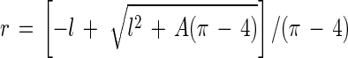 |
2 |
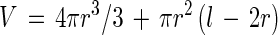 |
3 |
To estimate the precision of measurements, slides containing fluorescent latex microspheres (Polyscience Ltd.) having diameters of 0.52 and 0.80 μm were prepared in the same way as the slides containing bacteria, and the resulting images were processed with LabMicrobe.
Object classification.
There were basically only two main morphological classes of bacteria observed in significant numbers, rods (class R) and crescent-shaped vibrios (class V). The rods were subdivided into three classes based on elongation factors (length of the longest chord/mean width). Cocci and short rods (class R1) had elongation factors ranging from 1 to 3, short rods (class R2) had elongation factors ranging from 3 to 6, and long rods (class R3) had elongation factors ranging from 6 to 12. This classification was based on the assumption that bacteria usually increase in length to approximately twice the average length before they divide (9). A total of 60 objects belonging to each main class (classes R and V) were used as a training set, and 20 class R1 objects, 20 class R2 objects, and 20 class R3 objects were included to make sure that classes R1, R2, and R3 were represented equally (Fig. 2). Sixty objects identified as nonbacteria (class X) were also included (Fig. 2). The training set was introduced into LabMicrobe in the binary image form, and objects belonging to each class were pointed out to the program with the computer’s mouse prior to training. LabMicrobe traces the contours of objects by using a simple algorithm implemented by us and calculates the complex Fourier transform by using LabVIEW’s built-in signal-processing library. In this procedure, each complex number is the coordinate pair of each pixel in the contour. In Fourier space, contours were rendered independent of object position, rotation, and start position of the sampling point for the contour as described by Svarer (26). Shapes were subsequently simplified by using the eight lower spatial frequencies and their eight corresponding amplitudes, which together described the main characteristics of shape with the details (high frequencies) removed (Fig. 3). These 16 descriptors representing contour definitions were used to train a network consisting of 16 input nodes (one for each parameter), 5 intermediate nodes, and 3 output nodes (one for each class). The network was trained by LabMicrobe in an iterative process in which object definitions were chosen one by one at random and applied to the standard Back-Propagation algorithm (6) implemented by us for LabVIEW. The trained network was used by BatchMicrobe for the automatic classification procedure, using the Feed-Forward algorithm. A sigmoid activation function was used:
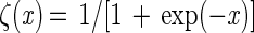 |
4 |
where x is the input at a given node in the network. The network was trained to put out a high number (0.9) at the node corresponding to the input configuration’s class and a low number (0.1) at other nodes. The network was saved after training and was subsequently used for classification. Classification of each object was based on the index of the output node having the highest value over 0.5. Classification was considered unsuccessful if no output node registered a value of more than 0.5. About 95% of all objects were classified in each image.
FIG. 2.

Entire training set used for the neural network classifier. The objects represent the main classes, including rods (classes R1, R2, and R3), vibrios (class V), and rejected objects (class X). The objects were chosen manually and were copied from images processed by the image analysis procedure described in the text.
FIG. 3.

Levels of detail achieved by using different numbers of Fourier coefficients (solid lines) for defining the contours of objects (stippled lines). Sixteen coefficients were used for this study.
Thymidine incorporation.
Bacterial biomass production as determined by thimidine incorporation was studied by using the method of Smith and Azam (23). [3H]thymidine was added to a concentration of 25 nM. A thymidine conversion factor of 1018 cells/mol was used (2).
FDC.
Dividing cells were defined as cells that contained two local intensity maxima. Such cells were detected by applying a filter which replaced each pixel in the image with the pixel having the maximum intensity in its neighborhood, including itself (Max), to the original gray scale image (G), subtracting G, thresholding to 1, and multiplying with the binary image (B) obtained after edge detection. This resulted in a binary image (D) with holes “punched” at the locations of local intensity maxima:
 |
5 |
Dividing cells were then identified as objects containing two holes. This method resembled the method described by Bloem et al. (3).
Statistics.
Data series were transformed by the natural logarithm when appropriate to approach normality. Significance levels in the analysis of variance were calculated by using the interaction term and pooling as described by Sokal and Rohlf (24). The statistical software SYSTAT was used.
Database management.
Parameters (i.e., cell volume, elongation factor, number of holes, and class of each object) were saved in a spreadsheet-formatted file for each image by BatchMicrobe. These parameters were fed through a utility program written in LabVIEW to segregate the data into classes based on classifications determined by the neural network and elongation factors. A second utility program was used to calculate cell volume histograms for each class. The histograms were then imported to a spreadsheet for final calculations and plotting.
RESULTS AND DISCUSSION
The strength of the image analysis method for performing large-scale surveys lies in its speed and consistency. This in turn allows sampling at a higher resolution than is practical manually. While automatic filtration and slide loading are mechanical problems that await practical solutions, the automatic image analysis procedure is a major step toward completely automatic monitoring. The processing times for images (1,000 by 1,018 pixels) when the procedure described above was used were roughly proportional to the number of objects (about four objects per s or one image per min), and computers that are many times faster than this are readily available. In this context, field results were used mainly to demonstrate that the image analyzer was able to identify interesting patterns of microbial activity in time and space within its limited resolution and that it was as accurate as a human in counting and measuring bacterial cells.
Object classification.
The most important task for the classifier in this survey was to segregate cell-shaped objects from other objects, such as detritus particles and particles created artificially as a result of noise and filtering. Figure 4 shows how the members of a subset of all of the objects from five images were classified by the machine. With the resolution used, only a few percent of the objects were classified incorrectly or were considered unsuccessfully classified. There was generally excellent agreement between manual and machine counts for samples collected in the summer months, but the machine consistently estimated higher bacterial concentrations in samples collected during the winter months (Fig. 5). An examination of individual microscope fields revealed that the machine included cell-shaped objects that fluoresced too faintly for the human counter to accept as bacterial cells, but these objects would have been counted if they had been brighter.
FIG. 4.

All objects that were obtained from five images from a sample collected at station US5 (week 32; depth, 8 m) and contained exactly two well-defined local intensity maxima (white dots surrounded by eight solid pixels). The presence of two well-defined local intensity maxima was used as the criterion to identify dividing cells. The image analyzer clearly classified these objects into correct classes, and only a few objects were classified as unidentifiable (? class). Only class R1 and R2 objects were used to obtain growth rate estimates.
FIG. 5.

Comparison of the bacterial total counts obtained with the image analysis procedure (■) and by manual counting (○) for three stations, two times of the year, and different depths.
The number of examples needed to train a neural network depends very much on the accuracy that is needed. For example, after the network was trained with just 4 examples of classes R and V, it performed almost as well as it did when it was trained with 60 examples (Fig. 2), but all 60 examples were needed to achieve consistent levels of accuracy of more than 90%. The network performed best when examples of all classes were used in roughly equal numbers for training.
Bacterial concentrations.
As mentioned above, there was good agreement between manual and machine counts for samples collected in the summer months, but the presence of faint particles in samples collected in the winter months resulted in disagreements (Fig. 5). There was also a statistically significant increase in the fraction of faint objects with depth. The nature of such faint objects is not known. Perhaps they were dead cells with intact membranes (29); it seems likely that they were bacterial in origin considering their shape and size.
Blooms of bacteria belonging to the four morphological classes occurred at all three stations, and the main peaks occurred during the summer at off-shore stations F9 and US5 and in the autumn at coastal station NB1 (Fig. 6). Although not representing strict taxonomic classes, small rods (class R1) medium rods (class R2), large rods (class R3), and crescent-shaped vibrios (class V) were distinguished. Most blooms peaked below the surface at a depth of 8 m. Class R1 accounted for the greatest number of bacteria. The number of class R2 bacteria was about one-third the number of class R1 bacteria, the number of class V bacteria was roughly the same as the number of class R2 bacteria, and there were fewer class R3 bacteria. An analysis of variance at the community level, based on the averages for five images determined by using time and depth as factors (Table 1), confirmed the significance of the visually distinguishable patterns in Fig. 6, in which gray scale intervals correspond roughly to the precision expected with 95% confidence.
FIG. 6.

Concentrations of morphological classes of bacteria at three stations in the Baltic Sea at different depths and times. Station F9 is a subarctic off-shore site, station US5 is an off-shore site, and station NB1 is a coastal site. Different shades correspond to concentrations that could be discerned with 95% confidence. w, week.
TABLE 1.
Analysis of variance of average bacterial concentrations of members of four morphological classes at three stations with time, with depth, and with time and depth
| Station | Parameter(s) |
P values
|
||||
|---|---|---|---|---|---|---|
| Class R1 | Class R2 | Class R3 | Class V | Total | ||
| F9 | Time | 0.001 | 0.001 | 0.001 | 0.01 | 0.001 |
| Depth | 0.001 | 0.01 | NSa | 0.01 | 0.001 | |
| Time and depth | 0.001 | 0.001 | NS | 0.001 | 0.001 | |
| US5 | Time | 0.001 | 0.001 | 0.001 | 0.001 | 0.001 |
| Depth | 0.05 | NS | NS | NS | NS | |
| Time and depth | 0.001 | 0.001 | 0.001 | 0.001 | 0.001 | |
| NB1 | Time | 0.001 | 0.001 | 0.001 | 0.001 | 0.001 |
| Depth | NS | NS | NS | NS | NS | |
| Time and depth | 0.001 | 0.01 | 0.05 | 0.01 | 0.001 | |
NS, not significant.
Studies performed with molecular probes have resolved the bacteria into about 10 to 20 dominant classes (18). Therefore, all of the classes (R1, R2, R3, and V) were presumably composed of several different species that were not discernible on the basis of morphology alone. A two-dimensional histogram of biovolume and elongation for the whole survey showed that the objects formed a continuum for both biovolume and elongation (data not shown) within the resolution of the image analyzer, which was limited by the digital representations of objects as collections of pixels. This indicated that the categories based on elongation factors (classes R1, R2, and R3) corresponded to windows in a virtually continuous elongation factor spectrum. The biovolume histogram within each window therefore reflected the average dominating biovolume within that window but actually represented several strains. Despite this problem, we made a number of observations which supported the theory that the bacterial community was at least partially resolved into subpopulations. (i) The histograms for each class in (Fig. 7) showed that classes R1 and R2 each displayed a Gaussian-shaped profile, as expected for two distinct populations. The profiles were truncated slightly at smaller cell sizes due to limitations in resolution. (ii) The widths of the class R1 and R2 histograms corresponded to roughly twice their modes (Fig. 7), which is consistent with the expectation that cells grow to approximately twice the average volume before they divide. Accordingly, cells identified as being in the process of dividing had biovolumes in the upper range of the histograms (Fig. 7). Class R3 exhibited very similar characteristics. The class V histogram had a peak for the group containing the smallest cells (0.023 μm3). The relative sharpness of the class V peak is consistent with the smaller cell size, but the true nature of the small cells must be investigated at higher resolution.
FIG. 7.

(R1, R2, R3, and V) Depth-integrated histograms for classes R1, R2, R3, and V, respectively, at station US5 for week 32. (R1D, R2D, R3D, and VD) Dividing cell histograms for classes R1, R2, R3, and V, respectively.
Bacterial cell volumes.
A resolution of 0.12 μm per pixel was chosen as a compromise between numbers of objects per image and precision in feature rendering. However, the biovolume estimates appeared to be quite precise. Measurements of fluorescent latex microspheres revealed a high level of precision for volume estimates in the bacterial size range (Table 2). The standard deviations for measured values are related to the digital sampling of the image formed by the optics. Volume is very sensitive to inaccuracies in measurements. An inaccuracy of just 0.5 pixel in object diameter results in a volume around the surface of the object which is greater than both the standard deviation and the deviation from the true value obtained when the edge detection procedure described above is used.
TABLE 2.
Measurement of two sizes of fluorescent latex beads of known size by image analysis
| Microsphere diam (μm) | Measured vol (μm3) | True vol (μm3) | % Overesti- mation |
|---|---|---|---|
| 0.52 | 0.081 ± 0.015 | 0.074 | 9 |
| 0.80 | 0.23 ± 0.012 | 0.27 | −12 |
Bacterial biovolume exhibited much less coherent patterns in space and time than did bacterial abundance. This may have been due in part to insufficient sampling in time. The standard deviations for measurements at each sampling location and sampling time were less than 12%. The precision of the image analyzer should allow discrimination of average biovolumes from five images with an accuracy of about 0.01 μm3 with 95% confidence. The biovolume modes for class R1 objects fluctuated mainly between 0.04 and 0.07 μm3. Class R1 accounted for total biovolumes ranging from 1 × 10⁻⁸ ml/ml in the winter months to 10 × 10−8 ml/ml in the summer months. In comparison, the class R2 biovolumes ranged from 0.5 × 10⁻⁸ to 3 × 10⁻⁸ ml/ml while the class R3 and V biovolumes ranged from 0.1 × 10⁻⁸ and 1 × 10⁻⁸ ml/ml.
Sieracki and Viles (21) performed a survey of bacteria abundance and cell size in the North Atlantic Ocean along a transect by using image analysis. These authors noticed that the particles segregated into two main groups, as determined by fluorescence intensity and particle size. The average cell size for the group containing smaller particles was less than 0.04 μm3, while the average cell size for the group containing larger cells was 0.11 μm3. Sieracki and Viles assumed that only the larger particles were bacteria but did not rule out the possibility that some of the smaller particles could have been small bacteria. A number of other surveys of the Sargasso Sea and of Gulf Stream and front waters revealed average bacterial cell sizes equivalent to those found by us in this survey of the Baltic Sea (21).
The biovolumes derived from the image analysis for the off-shore environments were similar to biovolumes reported by Häinenen (13) for the same area. The values for the coastal station, however, were about one-half those reported by Andersson et al. (1). Häinenen used ocular grids in the microscopic field to determine bacterial size, while Andersson et al. used exposure of diapositive photographs of microscopic fields digitized on a graphic tablet. The limited seasonal coverage of the two previous studies especially the study of Andersson et al., as well as differences in the methods used, may explain some of the differences between the results obtained.
Bacterial growth rates.
A number of objects classified as dividing were examined to check the validity of the dividing cell criterion (Fig. 4). The class R1 and R2 shapes included invaginations and/or local maxima located symmetrically at each end of a cell, as expected for cells undergoing division. This criterion appeared to be less reliable for classes R3 and V, but this finding was not considered to be very important since classes R1 and R2 accounted for the majority of the bacterial biomass and, presumably, biomass production. As a separate check, the dividing cell biovolume histogram had modes corresponding to roughly twice the average cell size for each class, as expected (Fig. 7).
Class R1 was differentiated from class R2 on the basis of elongation factors alone, but the same criterion did not logically apply to the corresponding dividing cells because of the much more complex cell shapes. It would have been theoretically possible to plot the frequency of dividing cells for each class, but elongation factors alone did not provide a strong enough criterion to identify the classes of dividing cells, so the frequencies were based on both class R1 and class R2 data.
The FDC exhibited coherent patterns with time and depth, and the maxima occurred during the summer months (Fig. 8). FDC ranging from 1 to 5% were consistent with the results of previous surveys performed with samples obtained from the Baltic Sea (11, 12) and are probably typical of all pelagic communities. The FDC reflects the growth rate of a population. As a first approximation, septum-building time appears to be independent of growth rate at a constant temperature, as observed in growth experiments (11, 12). Plotting FDC against growth rate at a constant temperature reveals an apparent linear relationship, but the slopes appear to vary with temperature and lines often do not go through the origin as expected (i.e., FDC ≠ 0 when μ = 0). The consequences of these observations can be partially explained by analyzing a simple model. Growth rate (μ) is dependent on the time that it takes a cell to grow to the point where it begins to divide (tG) plus the time that it actually takes to divide (tD):
 |
6 |
The proportion of cells in the dividing phase relative to the number of cells in the growing phase is the FDC:
 |
7 |
If tG from equation 7 is inserted into equation 6, then:
 |
8 |
The linear relationship is evident, and the slope can be interpreted as the division (septum-building) time. Any line not going through the origin cannot be explained by this model and might be interpreted as the result of cells that have been arrested in a critical phase of the cell cycle and allowed to accumulate. This can be a particularly important problem in continuous culture experiments that lack predators which remove dead cells. In contrast to the results of many continuous-culture experiments, the FDC values in this survey decreased to less than 1% during the winter (Fig. 8) which supports this interpretation. An examination of the relationships between FDC values and growth rates from chemostat experiments revealed that the septum-building time (tD) is approximately 1 h (11, 12):
 |
9 |
One problem with the FDC technique is that it depends on identification of the actual fraction of live cells, which may be quite small under ordinary circumstances (29). Special DAPI (4′,6-diamidino-2-phenylindole) staining techniques (29) and molecular techniques (18) to identify the live fraction are available. Another problem is that tD probably varies in different species. Assuming that equation 9 reflects the relationship between the FDC and the growth rate under typical conditions, the growth rate varied between 0.005 h−1 in the winter and 0.05 h−1 in the summer (Fig. 8).
FIG. 8.

Temperature, FDC based on data for classes R1 and R2 (see text), growth as calculated by using growth rate and concentration (Fig. 6) assuming that 30% of the cells were actively growing, and growth as estimated by thymidine incorporation (Thym. inc.) assays. w, week.
The results obtained with the thymidine incorporation method (7, 8) reflect the number of cells that exhibit active uptake of thymidine, whereas the FDC results reflect the growth rate in the growing fraction. The growth rates estimated by the thymidine incorporation method were comparable to the growth rates calculated by the FDC method if the fact that only a fraction of the identifiable cells were growing was taken into account. However, the patterns of growth with time obtained with the two methods were different, which left unanswered questions concerning what aspects of growth each method measures. For example, it is known that calibrating thymidine incorporation to growth rate is not a simple procedure, as it has been shown that thymidine metabolism occurs under certain conditions (15). On the other hand, the FDC procedure is labor intensive, which has limited its use. However, because of the new technique described here, extensive testing of the growth rate relationship can be anticipated.
Other plankton classes.
High accuracy in edge detection was a challenge for the image analyzer for cells as small as bacteria, but it was less important for larger cells. The design of the Laplace operator can be altered for analyzing such cells; e.g., a larger convolution kernel can be used to reduce noise sensitivity.
Even with shapes as simple as crescents (e.g., Class V), it is not easy to find geometric parameters that can be used to achieve the same certainty of classification as the certainty achieved with contour descriptions. For more complex shapes, the number of descriptors that define a contour can be adjusted until features of interest become visible (Fig. 3). There are, of course, a limited number of species which can be identified by contour alone. More complex network architectures and description parameters can be used, and remarkable precision in classification can be achieved (5).
ACKNOWLEDGMENTS
We thank the European Commission (contract MAS2 - CT93- 0077) and Umeå Marine Sciences Center (Umeå, Sweden) for financial support. We thank other members of the DIADEME project, including Lars Kai Hansen and Claus Svarer of the Technical University of Denmark, Bent Hygum of Roskilde University (Roskilde, Denmark), Ramon Massana and Carlos Pedrós-Alió of the Marine Science Institute of Spain, and Jorma Kuparinen and Susanna Hietanen of the Finnish Institute of Marine Research, for collaboration. We thank Umeå Marine Sciences Center for access to equipment and the Swedish National Environmental Monitoring Programme of the Baltic.
REFERENCES
- 1.Andersson A, Larsson U, Hagström Å. Size-selective grazing by a microflagellate on pelagic bacteria. Mar Ecol Prog Ser. 1986;33:51–57. [Google Scholar]
- 2.Bjørnsen P K, Kuparinen J. Determination of bacterioplankton biomass, net production and growth efficiency in the southern ocean. Mar Ecol Prog Ser. 1991;71:185–194. [Google Scholar]
- 3.Bloem J, Veninga M, Shepherd J. Fully automatic determination of soil bacterium numbers, cell volumes, and frequencies of dividing cells by confocal laser scanning microscopy and image analysis. Appl Environ Microbiol. 1995;61:926–936. doi: 10.1128/aem.61.3.926-936.1995. [DOI] [PMC free article] [PubMed] [Google Scholar]
- 4.Culverhouse P F, Ellis R, Simpson R G, Williams R, Pierce R W, Turnver J T. Automatic categorisation of five species of Cymatocyllis (Protozoa, Tintinnida) by artificial neural network. Mar Ecol Prog Ser. 1994;107:272–280. [Google Scholar]
- 5.Culverhouse P F, Simpson R G, Ellis R, Lindley J A, Williams R, Parisini T, Reguera B, Bravo I, Zoppoli R, Earnshaw G, McCall H, Smith G. Automatic classification of field-collected dinoflagellates by artificial neural network. Mar Ecol Prog Ser. 1996;139:281–287. [Google Scholar]
- 6.Frankel D S, Olson R J, Frankel S L, Chisholm S W. Use of a neural net computer system for analysis of flow cytometric data of phytoplankton populations. Cytometry. 1989;10:540–550. doi: 10.1002/cyto.990100509. [DOI] [PubMed] [Google Scholar]
- 7.Fuhrman J, Azam F. Bacterioplankton secondary production estimates for coastal waters of British Columbia, Antarctica, and California. Appl Environ Microbiol. 1980;39:1085–1095. doi: 10.1128/aem.39.6.1085-1095.1980. [DOI] [PMC free article] [PubMed] [Google Scholar]
- 8.Fuhrman J, Azam F. Thymidine incorporation as a measure of heterotrophic bacterioplankton production in marine surface waters: evaluation and field results. Mar Biol. 1982;66:109–120. [Google Scholar]
- 9.Grover N B, Woldringh C L, Zaritsky A, Rosenberger R F. Elongation of rod-shaped bacteria. J Theor Biol. 1977;67:181–193. doi: 10.1016/0022-5193(77)90192-8. [DOI] [PubMed] [Google Scholar]
- 10.Haas L W. Improved epifluorescence microscopy for observing planktonic micro-organisms. Ann Inst Oceanogr. 1982;58:261–266. [Google Scholar]
- 11.Hagström Å, Larsson U. Diel and seasonal variation in growth rates of pelagic bacteria. In: Hobbie J E, Williams P J L, editors. Heterotrophic activity in the sea. New York, N.Y: Plenum Publishing Corp.; 1984. pp. 249–262. [Google Scholar]
- 12.Hagström Å, Larsson U, Hörstedt P, Normark S. Frequency of dividing cells, a new approach to the determination of bacterial growth rates in aquatic environments. Appl Environ Microbiol. 1979;37:805–812. doi: 10.1128/aem.37.5.805-812.1979. [DOI] [PMC free article] [PubMed] [Google Scholar]
- 13.Heinänen A. Bacterioplankton in the open Baltic Sea. Ph.D. thesis. Helsinki, Finland: University of Helsinki; 1992. [Google Scholar]
- 14.Hobbie J E, Daley R J, Jasper S. Use of Nuclepore filters for counting bacteria by fluorescence microscopy. Appl Environ Microbiol. 1977;33:1225–1228. doi: 10.1128/aem.33.5.1225-1228.1977. [DOI] [PMC free article] [PubMed] [Google Scholar]
- 15.Hollibaugh J T. Limitations of the [3H]thymidine method for estimating bacterial productivity due to thymidine metabolism. Mar Ecol Prog Ser. 1988;43:19–30. [Google Scholar]
- 16.Marr D, Hildreth E C. Theory of edge detection. Proc R Soc Lond B Biol Sci. 1980;207:187–217. doi: 10.1098/rspb.1980.0020. [DOI] [PubMed] [Google Scholar]
- 17.Massana R, Gasol J M, Bjørnsen P K, Blackburn N, Hagström Å, Heitanen S, Hygum B H, Kuparinen J, Pedrós-Alió C. Measurements of bacterial size via image analysis of epi-fluorescence preparations: description of an inexpensive system and solutions to some of the most common problems. Sci Mar. 1997;61:397–407. [Google Scholar]
- 18.Pinhassi J, Zweifel U L, Hagström Å. Dominant marine bacterioplankton species found among colony-forming bacteria. Appl Environ Microbiol. 1997;63:3359–3366. doi: 10.1128/aem.63.9.3359-3366.1997. [DOI] [PMC free article] [PubMed] [Google Scholar]
- 19.Porter K G, Feig Y S. The use of DAPI for identifying and counting aquatic microflora. Limnol Oceanogr. 1980;25:943–948. [Google Scholar]
- 20.Sieracki M E, Viles C. Color image-analyzed fluorescence microscopy: a new tool for marine microbial ecology. Oceanography. 1990;3:30–36. [Google Scholar]
- 21.Sieracki M E, Viles C L. Distributions and fluorochrome-staining properties of sub-micrometer particles and bacteria in the North Atlantic. Deep Sea Res. 1992;39:1919–1929. [Google Scholar]
- 22.Simpson R, Williams R, Ellis R, Culverhouse P F. Biological pattern recognition by neural networks. Mar Ecol Prog Ser. 1992;79:303–308. [Google Scholar]
- 23.Smith D C, Azam F. A simple, economical method for measuring bacterial protein synthesis rates in seawater using 3H-leucine. Mar Microb Foodwebs. 1992;6:107–114. [Google Scholar]
- 24.Sokal R R, Rohlf F J. Biometry. W.H. New York, N.Y: Freeman and Co.; 1995. [Google Scholar]
- 25.Stokseth P A. Properties of a defocused optical system. J Optic Soc Am. 1969;59:1314–1322. [Google Scholar]
- 26.Svarer C. Neural networks for signal processing. Ph.D. thesis. Lyngby, Denmark: Technical University of Denmark; 1994. [Google Scholar]
- 27.Viles C L, Sieracki M E. Measurement of marine picoplankton cell size by using a cooled, charge-coupled device camera with image-analyzed fluorescence microscopy. Appl Environ Microbiol. 1992;58:584–592. doi: 10.1128/aem.58.2.584-592.1992. [DOI] [PMC free article] [PubMed] [Google Scholar]
- 28.Williams S C, Verity P G, Beatty T. A new staining technique for dual identification of plankton and detritus in seawater. J Plankton Res. 1995;17:2037–2047. [Google Scholar]
- 29.Zweifel U L, Hagström Å. Total counts of marine bacteria include a large fraction of non-nucleoid-containing bacteria (ghosts) Appl Environ Microbiol. 1995;61:2180–2185. doi: 10.1128/aem.61.6.2180-2185.1995. [DOI] [PMC free article] [PubMed] [Google Scholar]