Abstract
Nanofibers have gained much attention because of the large surface area they can provide. Thus, many fabrication methods that produce nanofiber materials have been proposed. Electrospinning is a spinning technique that can use an electric field to continuously and uniformly generate polymer and composite nanofibers. The structure of the electrospinning system can be modified, thus making changes to the structure, and also the alignment of nanofibers. Moreover, the nanofibers can also be treated, modifying the nanofiber structure. This paper thoroughly reviews the efforts to change the configuration of the electrospinning system and the effects of these configurations on the nanofibers. Excellent works in different fields of application that use electrospun nanofibers are also introduced. The studied materials functioned effectively in their application, thereby proving the potential for the future development of electrospinning nanofiber materials.
Keywords: electrospinning, nanofibers, carbon fibers, polymer fibers, composite fibers
1. Introduction
Nanofiber materials have attracted much attention because of their extraordinary advantages that can bring many benefits to applications [1]. Since the interaction of the materials with the working environment happens on their surface, improvement of the surface area can greatly enhance their working performance. Many studies have proposed that nanofiber materials possess a surface area much greater than bulk or 2D (sheet) materials [2,3]. Meanwhile, they are still imbued with the physical properties of the material from which they are built. These properties can help the materials to be applied in some applications that require a certain physical strength [4,5,6,7,8].
Many fabrication methods for nanofibers have been proposed in the literature, including the uses of hard, soft, and free templates. While hard and soft templates release a large amount of chemicals into the environment, the free template seems to be more environment-friendly, in which case, electrospinning is a free template technique that uses an electrical field to fabricate the polymer and polymer composite nanofibers [9,10,11,12,13]. This technique requires a very limited amount of solvent, which is used to dissolve the polymer into a high-viscosity solution. After the shape of fibers is applied to the solution, the solvent is released and leaves the material in the shape of the nanofibers [14]. The polymer used in the process must be dissolved in the solvent, which limits the selection of polymers that can be spun. However, some of the available commercial polymers are dissolvable in a low boiling point solvent, so such limitation is almost negligible.
Though the mechanism of electrospinning is simple, many improvements can be carried out on the components of the system [15,16,17]. Thereby, the morphology of the produced nanofibers can be greatly altered. There are reports that described further treatment processes that have been carried out on the electrospun nanofibers [18]. As collected, the nanofibers usually stack over each other, layer after layer, and form a membrane. They can be used as a membrane sheet and built up to a 3D structure [19,20,21]. On the other hand, carbonization can transform most of the existing polymer nanofibers into carbon nanofibers (CNFs). These CNFs showed great potential in electrochemical application, which has gained increased interest in recent years [22].
Herein, the manuscript proposes a critical review of the electrospinning system. First, the modifications made to components (electrospun material, nozzle, and collector) of the electrospinning system are introduced, together with the effects on the shape of nanofibers. Later, the recent applications of nanofibers that are fabricated by electrospinning are suggested. Many modifications of nanofibers, including freeze-drying, deposition, and thermal treatment, can be applied to achieve suitable properties for many advanced applications.
2. The Electrospinning System
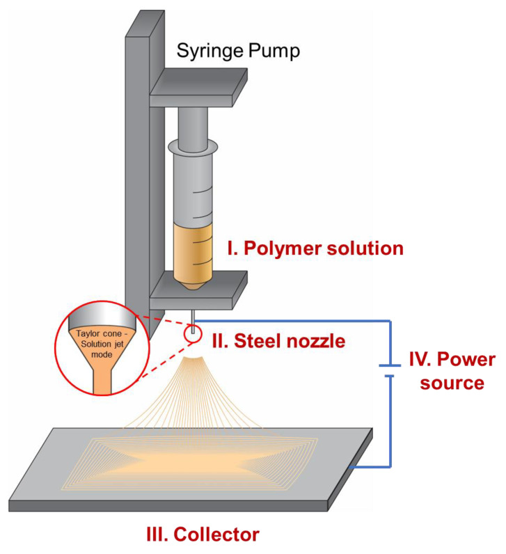
The basic electrospinning system consists of a syringe pump, material solution, nozzle, collector, and power source (Figure 1). The materials used in an electrospinning system are usually solutions where the polymers are well dissolved in an easy-to-vaporize solvent. The syringe pump injects the polymer solution from a syringe into the connected metal nozzle, where it is charged by a high-voltage electric field. The polymer solution inherits the charge from the nozzle, which is opposite to the charge of the collector [23]. Thus, the solutions are drawn toward the surface of the collector. Here, two processes happen simultaneously. First, while the droplet of the polymer solution is held at the outlet of the nozzle, it is stretched and pulled over the collector [24,25]. During this process, the high difference between the areas of the nozzle and the collector splits the solutions and forms nanoscale diameter fibers [26]. Secondly, the split solution has a high surface area, which makes it easier for the solvent trapped between the polymer matrix to be released, leaving solid polymer fibers. Despite the simple mechanism and advantages in product quantity, many factors can affect the outcome properties of the fibers and need to be optimized thoroughly with each material and condition. These factors may derive from the materials and systems configuration, as well as the environment [27]. The necessary power needed to operate an electrospinning system is very high. There is no electron flow (amplitude is near zero amperes) since there is no direct contact between the nozzle and collector. Meanwhile, the voltages may vary from a few kilovolts up to 30 kV, which builds up a difference in the electrical potential between the nozzle and the collector, creating an electric field. Hence, safety during the working of the system should be of high priority. The working mechanism of electrospinning is based on this electric field. For the nanofibers to form uniformly in diameter, the applied voltage has to be maintained stably over time. The higher applied voltage can result in the material solution being pulled away from the nozzle faster. Thus, the applied potential is an important factor to be controlled, so that the solution droplet is stable in the cone-jet mode [28,29]. In this mode, the nanofibers can be generated with a more uniform diameter. By controlling the applied voltage, which can be easily optimized during the operation of electrospinning, the diameter of the nanofibers can also be controlled [30]. The higher the voltage, the smaller the diameter of the nanofibers. On the other hand, the diameter of the nanofibers is also highly affected by the material solution properties, system configuration, as well as environment, which is to be discussed in the following sections of the manuscript. However, there is no significant modification that can be carried out on the power source in the electrospinning system that can result in a change in the configuration of the nanofibers.
Figure 1.
Standard electrospinning system, including a syringe pump, a syringe containing electrospun solution, a steel nozzle, a planar collector, and a power source.
2.1. Polymer Solutions
2.1.1. Solutions Using One Polymer
A solution with one or many polymers that are well dissolved in a low boiling point solvent can be used as material for the electrospinning process. The viscosity of the solution material can be considered the most important factor when operating an electrospinning system [31,32]. It can be affected by the following common factors: the molecular weight of the polymer, the functional structure of the polymer, and the viscosity of the solvent [33]. It is well known that the higher molecular weight of the polymer chain provides higher viscosity of the solution [34]. However, the contribution of the polymer molecular weight can be considered small, compared to the interaction between the polymer chains. The interchain interactions are induced by the functional groups of the polymer. Most of the interactions that are commonly encountered are hydrogen and van der Waals interactions. As the concentration of polymer increases, these interactions become stronger. Such a phenomenon can occur because shorter distances between the functional groups strengthen the interchain interactions. It was found that the solvent can also contribute to the viscosity of the solution, but this is also dependent on the interaction between solvent and polymer [35]. The viscosity of the polymer solution has a large impact on the shape of the electrospun fiber. The higher the viscosity, the harder it is for the solution to be split during the spinning process, and the larger the size of the outcome fibers. On the other hand, when the viscosity is too low, the solution quickly leaves the nozzle toward the collector as a drop of solution. It is noted that the electrical conductivity of the solution also affects the electrospinning process [36]. Table 1 suggests some works that use simple polymer solutions. While seeing that the simple polymer solution is the basic material for the electrospinning process, three groups of modification can be made: solutions using mixed polymer, block copolymer, and polymer composite, respectively, as described below:
Table 1.
Simple polymer solutions that had been used in electrospinning.
| Polymer | Solvent | Reference |
|---|---|---|
| PEO 1 | Water/chloroform | [37] |
| PVA | Water | |
| CA | Acetone | |
| PANi 2/PEO | Chloroform | [38] |
| PEO | Isopropyl alcohol | [39] |
| Polycarbonate | DMF 3/THF 4 | |
| Polyurethane | DMF | [40] |
| Polycaprolactone | Acetone | [41] |
| PVP | Ethanol/water | [42] |
| PANi | Formic acid | [43] |
| Ppy 5 | DMF | [44] |
| Magnesium linked PEDOT:PSS 6 | DI water 7 | [45] |
| Collagen | HFIP 8 | [46] |
| Gelatin | Aqueous acetic acid (90%) | [47] |
| HA-DTPH 9 | Dulbecco’s modified eagle’s medium | [48] |
1 Polyethylene oxide. 2 Polyaniline. 3 N,N-dimethylformamide. 4 Tetrahydrofuran. 5 Polypyrrole. 6 poly(3,4-ethylenedioxythiophene) polystyrene sulfonate. 7 De-ionized water. 8 1,1,1,2,2,2-hexafluoro-2-propanol. 9 3,3′-dithiobis(propanoic dihydrazide)-modified hyaluronic acid.
2.1.2. Solutions Using Mixed Polymer
The multiphase structures of the electrospun nanofibers are formed through the phase separations of the polymers in an emulsion solution. Even though the polymers are well mixed in the solvents, the surface tension between materials separates them from each other. Here, one of the polymers acts as the continuous phase (surrounding), while the other acts as the discontinuous phase (droplet). As the solvent is removed, the polymer hardens and forms many complicated structures [49,50]. At the nozzle, the discontinuous phase material is concentrated in the center, while surrounded by the continuous phase material. This process is named the self-assembly process, in which the materials reorganize themselves. In the case of electrospun nanofibers, polymers that exist within the solution will try to reorganize following the direction of the nanofibers. Note that surfactants can also be used to create an emulsion between hydrophobic and hydrophilic solutions (for example chloroform and water) for electrospinning [51]. Table 2 presents the emulsion mixtures of polymer solutions that can self-assemble to create multiphase electrospun nanofibers.
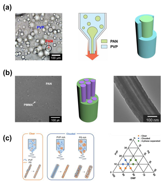
Lee et al. electrospun the solution containing a mixer of poly(acrylonitrile) (PAN) and poly(vinylpyrrolidone) (PVP) (Figure 2a) [52]. It has been proven that the viscosity of polymer components participating in the mixture can directly affect the disposition of polymers in the nanofibers. Here, the PVP was the continuous phase of low viscosity, while PAN was the discontinuous phase of much higher viscosity in the mixed solution. The constructed electrospun nanofibers contained a single large PAN core in the center covered by the PVP shell. However, when the mixed solution of poly(methyl methacrylate) (PMMA) and PAN was used for electrospinning (also demonstrated by Lee et al.), the structure of the nanofibers was much different (Figure 2b) [53]. The PAN was the continuous phase and covered the PMMA when the electrospun fiber was formed. Because the PMMA solution had lower viscosity compared to the PAN solution, the droplets of PMMA were very small in size and created multicore/multichannel inside the nanofibers. After the fiber was carbonized and PMMA decomposed, the PAN shell was carbonized into multichannel carbon nanofibers (MCNFs). Though the size of the channels was small, the structure with multichannel provided great porosity for the carbon fibers.
Figure 2.
(a) Electrospinning process of PVP/PAN mixture, both are dissolved in DMF [52]. Copyright 2011, American Chemical Society. (b) The formation of PAN nanofibers containing PMMA multicore using electrospinning [53]. Copyright 2017, Wiley. (c) The effect of ration between PVP and PS over the formation of nanofibers with electrospinning [54]. Copyright 2022, American Chemical Society.
The ratio between the component polymers has been proven to be a decisive factor that affects their contribution in volume within the nanofibers. Narumi et al. electrospun the mixed solution of poly(styrene) (PS) and PVP in the N,N-dimethylformamide (DMF) solvent (Figure 2c) [54]. The authors investigated the structure of nanofibers by dissolving the PVP in the fibers with water. Note that there are polymer ratios that give phase separation, and these solutions cannot be used for electrospinning. When the PVP was the majority amount in the mixture, they covered the outside of the fibers, and PS formed a single core in the fibers. On the other hand, the PS-rich material formed fibers containing multi-PVP cores in the PS cover. In summary, the polymer of a larger amount usually covers the other polymer, though the structure of the core is highly dependent on the properties of the studied polymer.
Table 2.
Combination of solutions, that can form the emulsion system for electrospinning.
| Solution 1 | Solution 2 | Reference | ||
|---|---|---|---|---|
| Polymer | Solvent | Polymer | Solvent | |
| PEO | Chlorobenzene | PQT-12 1 | Chlorobenzene | [55] |
| PEO | DI water | Fibrinogen | Distilled water | [56] |
| Nomex 2 | DMAc 3 | Carboxylated nitrile butadiene rubber | Chloroform | [57] |
| PAN | DMF | PI 4 | DMF | [58] |
| PPDO 5-b-PEG | Chloroform/DMF | PLA 6 | Chloroform/DMF | [59] |
| Lysozyme/methyl cellulose | PBS 7 | poly (DL-lactic acid) | Chloroform | [60] |
| PLGA 8/Span80 9 | Chloroform | FITC 10 | DI water(or PBS) | [61] |
| PCL 11 | Chloroform | Hyaluronan | Chloroform | [62] |
| PCL/Span80 | Chloroform | PCL/Span80/MH 12 | Distilled water | [63] |
| PHBV 13/Span80 | Chloroform | PHBV/Span80/HF | Distilled water | |
1 poly(3,3′-didodecyl quarter thiophene). 2 Poly(m-phenylene isophthalamide). 3 N,N-Dimethylacetamide. 4 Polyimide. 5 Poly(p-dioxanone. 6 Poly(lactic acid). 7 Phosphate buffer saline. 8 Poly(lactic-co-glycolic acid). 9 Surfactant. 10 Fluorescein isothiocyanate isomer. 11 Polycaprolactone. 12 Metformin hydrochloride (Drug). 13 Poly(3-hydroxybutyric acid-co-3-hydroxyvaleric acid).
2.1.3. Solutions Using Block Copolymer
Another option for the material for single nozzle electrospinning is the use of block copolymers. Although there is no major phase separation, the self-assembly process can also occur at the nanoscale [64]. The volume fraction of the block copolymer will affect its structure after the self-assembly process [65,66]. Table 3 presents some of the block copolymers that have been used in electrospinning.
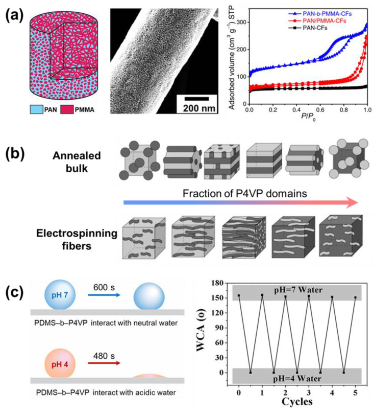
Recently, Zhou et al. proposed carbon fibers that are the result of the carbonization of the PMMA−PAN block copolymer (Figure 3a) [67]. The fibers have been proven to contain microporous structures that can significantly improve the efficiency in the application of energy storage. However, a structure that has pores that are too small in size can bring certain disadvantages. For example, in the application of the capacitor (energy storage), the carbon material needs to be mixed with a polymer binder and conductive carbon black during device fabrication. In the study, the authors did not use any polymer binder or conductive carbon powder. The use of polymer binders can cover the porous structure, thereby greatly limiting the measured capacity.
Figure 3.
(a) The electrospun nanofibers fabricated from block copolymer of PAN and PMMA [67]. Copyright 2019, Science. (b) The effect of P4VP fraction in the block copolymer PSS-b-P4DP over the self-assembled structure of nanofibers [68]. Copyright 2007, Royal Society of Chemistry. (c) PDMS-b-P4VP, whose surface tension changed in contract with pH 4 and pH 7 water [69]. Copyright 2016, American Chemical Society.
Ruotsalainen et al. made a clear investigation of the block copolymer polystyrene-block-poly(4–vinyl pyridine) (PSS–b–P4DP) fraction’s ratios and their effect on the morphology of the fibers (Figure 3b) [68]. The proposed assembly structure can provide an excellent example of how, after the electrospinning process, the block copolymer assembles itself. As the ratio of the polymer fractions in the copolymer changed, the structure of the self-assembly material also changed. Thereby, the properties of the nanofibers may also be dramatically changed, both physically and chemically, together with their interface interaction. This phenomenon can greatly widen their field of application.
The different individual blocks in the block copolymer can exhibit their various properties independently. However, their interaction can contribute, and make the material suitable to be applied as a smart interface material. Li et al. introduced the electrospun block polymer poly(dimethylsiloxane)–block-poly(4–vinylpyridine) (PDMS–b–P4VP) as a switchable oil/water separate membrane (Figure 3c) [69]. Up point interacts with acidic water (potential of hydrogen, pH is smaller than 4), the poly(4–vinylpyridine) (P4VP) block of the polymer fibers stretches out and makes the surface of fiber highly hydrophilic. Meanwhile, the interaction with water with higher pH makes the poly(dimethylsiloxane) (PDMS) extend and stretch out. The PDMS at the surface makes the membrane fiber highly hydrophobic.
Table 3.
The block copolymers that were used in electrospinning.
| Block Copolymer | Solvent | Reference |
|---|---|---|
| PMMA−PS | DMF | [70] |
| PMTFPS 1−PMMA | THF/DMF | [71] |
| PEG−PCL | DCM 2 | [72] |
| PEG−PLA | DMF | [73] |
| PS−PPG 3 | DMF | [74] |
| PEO −PPO 4−PEO | Chloroform | [75] |
| PCL−PTHF−PCLPCL 5 | Chloroform/methanol | [76] |
| PE−PVA 6/PLA | Chloroform | [77] |
| PS−PDMS 7/PS | THF/DMF | [78] |
| PLGA 8/antibiotic (fusidic acid and sodium fusidate) | THF/DMF | [79] |
1 Poly[methyl(3,3,3-trifluoropropyl)siloxane]. 2 Dimethyl carbonate. 3 Polypropylene glycol. 4 Poly(p-phenylene oxide). 5 Polycaprolactone–polytetrahydrofuran–polycaprolactone. 6 Polyethylene-co-vinyl acetate. 7 Polydimethylsiloxane. 8 Poly(D,L-lactic acid-co-glycolic acid).
2.1.4. Solutions Using Polymer Composite
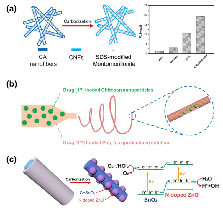
Another modification that has been carried out on the electrospun nanofiber, besides the selection of polymer materials, is the addition of fillers into the polymer matrix [80]. Though most of the common materials used in the electrospinning system are polymer solutions, other materials of limited amounts (organic, inorganic) can be mixed and spun together with the polymer. The results of such effort are the composite nanofibers, where the fillers are dispersed uniformly in the polymer matrix. The necessary condition for the formation of uniform fibers is that the filler must be mixed well in the solution, together with the polymer. Thus, the filler materials have to be chosen for their excellent interaction with the polymer and solvent (hydrophobic–hydrophobic or hydrophilic–hydrophilic). In the case where the fillers do not interact well with the solvent, the filler cannot disperse in the precursor solution. When the fillers do not have good interaction with the polymers, aggregation may occur while the solvent evaporates and the polymer reorganizes its structure. Table 4 presents the electrospinning processes that have been proposed for the fabrication of polymer composite nanofibers. Cai et al. introduced composite nanofibers that were constructed from cellulose acetate (CA) fibers and montmorillonite modified with surfactant sodium dodecyl sulfonate (SDS) (Figure 4a) [81]. The modification of the surfactant improved the dispersity of filler material in the polymer matrix, making a uniform structure for composite nanofibers. Thereafter, the fibers undergo carbonization, and CA turns to carbon nanofibers (CNFs). The results were products that have suitable properties to be used for heavy metal ions adsorption. The combination of CNFs and modified montmorillonite filler has been proven to significantly improve the performance of materials in the application.
Table 4.
The solutions for the electrospinning of polymer composite nanofibers.
| Polymer Carrier | Solvent | Filler | Reference |
|---|---|---|---|
| PVA | DI water | Ag NPs | [84] |
| Polyvinyl butyral | Isopropyl alcohol/water | Fe(NO3)3, Co(NO3)2, or Ni(NO3)2 | [85] |
| PVA | DI water | Cu(CH3COO)2 | [86] |
| PVP | DMF/DI water | H2PtCl6 | [87] |
| PVP | DMF/DI water | H2PtCl6/HAuCl4 | |
| Poly(acrylic acid) | Ethanol | HAuCl4 | [88] |
| PVP | Ethanol | Al(CH3COCHCOCH3)3 | [89] |
| PVA | DI water | Ce(NO3)3 | [90] |
| PMMA | DMF/chloroform | C4H6MnO4 | [91] |
| PVA | DI water/propanol/and isopropanol | SnCl4 | [92] |
| PVP | Ethanol/acetic acid | Ti(OBu)4 | [93] |
| PAN | DMF | Melamine–trithiocyanuric acid | [94] |
Figure 4.
(a) The nanofibers composite of carbon and surfactant sodium dodecyl sulfonate filler [81]. Copyright 2017, Elsevier. (b) The fabrication of chitosan/poly (ε−caprolactone) nanofiber composite nanofibers for the application of drug delivery [82]. (c) N−doped ZnO nodule attached to the carbon nanofibers contains SnO2, the special structure that greatly enhanced the efficiency of catalyst activity [83]. Copyright 2012, Royal Society of Chemistry.
Most of the applications where composite nanofibers are used have fillers playing the role of the main active material. Thus, the fillers should stay in the position favoring their activity. Wang et al. developed the chitosan/poly (ε-caprolactone) nanofiber composite used to store medicine and release it after a predicted period (Figure 4b) [82]. In the study, the chitosan particles that store the medicine chemicals were well covered in the polymer fiber, even if the particles were larger than the fiber diameter. This structure prevents medicine loss during the delivery process. On the other hand, there are applications where the fillers must have interacted with the electrolyte. For the material to effectively function, the particles should be concentrated on the surface of the fibers through a variety of fabrication methods. In the application of visible light catalysts, Lee et al. used a mixture of two solutions (PAN−SnCl4 and PVP−ZnAc2) to fabricate PAN composite nanofibers as the precursor for carbonization (Figure 4c) [83]. As demonstrated, the PAN formed a single core, while PVP formed the cover shell. After the carbonization, while PAN turned into CNFs containing SnO2, PVP decomposed completely and left the ZnO nodule attached to the wall of the fiber. The ZnO nodule greatly exposed to the electrolyte helps improve the electron exchanges, thereby creating the optimized condition for the activity of catalysts.
2.1.5. Solutions Using Co-Solvent
In the electrospinning technique, a low boiling point solvent and a high boiling point solvent can be combined as co-solvents for the electrospinning solution. Because the vaporization rate of the solvent has a great impact on the formation of the polymer nanofibers, modification of the solvent can generate some special morphological structure for the material. On the other hand, the dependence of solvent vaporization rates on the environment can also vary, thereby opening the opportunity for the structure to be modified even further [95,96]. Though many results can be harvested from the modifications of co-solvent electrospinning, it also means that they are very sensitive to the fabrication conditions. Thus, they post many requirements for controlling the fabrication process. Table 5 presents some examples that used multi-solvent to modify the morphology of polymer nanofibers. In addition to that, phase separation that may occur between the solvents is a very important factor that needs attention during the operation of electrospinning. Phase separation can be triggered due to differences in the properties of solvents like hydrophilicity, surface tension, and electrical conductivity [97].
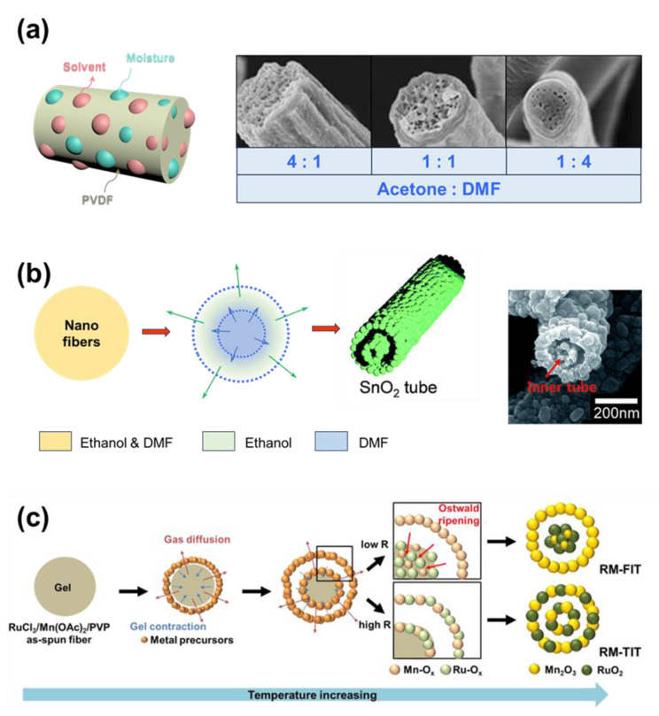
Zaarour et al. used the combination of acetone and DMF to prepare the solution for the production of electrospun polyvinylidene fluoride (PVDF) nanofibers (Figure 5a) [98]. While acetone is easy to vaporize, DMF is harder to vaporize. As the acetone vaporized, the water molecules were drawn into the fibers [99]. If the polymer fibers are spun in an environment with low humidity, the water droplets can quickly leave the fibers. Because PVDF cannot be dissolved in water, the trapped water molecule can create pores in the structure of nanofibers. However, the higher the humidity, the more difficult it is for the polymer matrix to release the water. Water nucleation growth occurs, and the water droplet can grow to a larger size. Finally, macro-size pores form in the structure and increase the size of fibers. In addition, the ratio of acetone over DMF affects the size of the pores and the polymer fibers’ diameter.
Figure 5.
(a) Porous PVDF nanofibers, whose porous structure was created by the mixture of solvents (acetone and DMF) [98]. Copyright 2018, Springer. (b) The difference in evaporation rate of methanol and DMF solvent formed the tube-in-tube structure of SnO2 nanofibers [100]. Copyright 2017, Royal Society of Chemistry. (c) The effect of heating rate on the inner tube structure of the Mn2O3/RuO2 tube-in-tube [101]. Copyright 2016, American Chemical Society.
When there are fillers in the solution, special structures can also be formed. Lee et al. introduced a tube-in-tube structure of SnO2 that can be generated simply using a thermal treatment on composite nanofibers (Figure 5b) [100]. The PVP polymer and SnCl2 were dissolved with a mixture of DMF and methanol. After the solution was spun with the electrospinning technique, the nanofibers underwent the calcination process at 600 °C with a well-controlled heating rate. As the methanol quickly vaporized at lower temperatures, a layer of SnO2 formed at the outside wall of the fibers. Meanwhile, the DMF solvent vaporizes slower and forms another layer of SnO2 in the center. Note that PVP decomposed completely at high temperatures; thereby, no carbon is produced after the process. Here, the heating rate of the calcination process can decide the resultant shape of the SnO2 core layer. While the SnO2 molecules can rearrange themselves during a slow vaporization rate (slow heating rate) and the fiber solidifying, the high vaporization rate results in the hollow structure of the core. Meanwhile, Yoon et al. dissolved PVP in DMF and water together with RuCl3/Mn(OAc)2 (1:2) (Figure 5c) [101]. The RuCl3 and Mn(OAc)2 are the precursors of the RuO2/Mn2O3 complex. During the calcination process, the DMF quickly vaporizes, forming a hollow metal oxide outer shell, since it is the first solvent to vaporize. Water is vaporized at higher temperatures, and finally forms the core of the metal oxide fibers. In this study, the heating rate of the calcination process also plays an important role in the formation of the morphology of the fibers.
Table 5.
The electrospinning solutions used the difference between solvents to alter the morphology of nanofibers.
| Polymer | Solvent 1 | Solvent 2 | Reference |
|---|---|---|---|
| Poly (2-hydroxethyl methacrylate) | Formic acid | Ethanol | [102] |
| PS | DMF | Diethyl Formamide | |
| Nylon 6 | HFIP | DMF | [103] |
| Nylon 6/NLS 1 | HFIP | DMF | |
| PVC 2 | THF 3 | DMF | [104] |
| PLA | DCM | Ethanol | [105] |
1 Montmorillonite. 2 Polyvinyl chloride. 3 Tetrahydrofuran.
2.2. Nozzle
2.2.1. Single Steel Nozzle
As mentioned, the nozzle is one of the main components of the electrospinning system. That is the medium to transport the potential charge from the power source to the solution. The nozzle is usually made from stainless steel to prevent any unwanted reaction while having high electrical conductivity. The used nozzle can have different sizes depending on the viscosity of the material solution; the high-viscosity solution with high surface tension can make it hard for the solution to flow through a small sized nozzle. However, the nozzle with a higher gauge (smaller size) can produce smaller nanofibers. With one single nozzle acting as the only output for the material solution, there are fewer parameters to control. However, the spinning process can be conducted stably, and uniform nanofibers can be collected. Therefore, to date, it remains a favorable technique in the electrospinning process. Note that many simple nozzles can be used at the same time, and each of them can be provided with different polymer solutions [106,107]. The results are a mixture of different nanofibers with different properties, both physical and chemical, laid on top of one another. Though separated, the fabricated fibers can have amazing interactions. Ding et al. first used electrospinning to fabricate a layer of polyethyleneimine (PEI) fibers, which was used as a support for the much smaller nanofibers of polyamide 6 (PA) [108]. The diameter of the PA fibers is only around 30 nm. With the large size of PEI fibers, the distance between the PA fibers networks was greatly enhanced. The performance of PA nanofibers in the application of gas sensing is greatly improved since the gas can easily penetrate and interact with the sensing material. However, as the need for more complicated structures has increased, modifications have been made to create special structures for the fibers. With these modifications, many polymers can coexist within the nanofibers while being separated in phases, even if they are hydrophobic–hydrophilic polymers.
2.2.2. Coaxial Nozzle
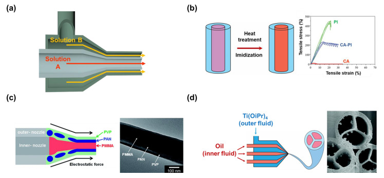
The coaxial nozzle (dual nozzle) is a special nozzle, where a larger nozzle covers a smaller nozzle (Figure 6a). The nozzle can give fibers a structure that has many layers, called core–shell nanofibers. The two nozzles in the coaxial nozzle are fed with two different polymer solutions, and the feed rates can be individually controlled. Yet, the feed rate is an important condition that has to be well controlled, so that the fibers can be generated uniformly. The method is normally used for two polymer solutions that are not intended to be mixed. The usual results of the technique are fibers with a single large core covered in a shell layer. The inner material can be removed to create a large channel in the center of the fibers or be the skeleton providing excellent physical properties for the fibers [109,110]. The number of layers can also be increased in number, creating wider choices for modifications [111]. Table 6 presents some combinations of solutions that were chosen for the coaxial nozzle.
In the application of oil–water separation, the membrane material must have good physical properties. The coaxial nozzle was used by Ma et al. to fabricate the fibers with the polyimide (PI) as the core, and CA as the shell of the fibers (Figure 6b) [112]. As it is nearly impossible to dissolve PI, poly amide acid (PAA) solution was synthesized, and used for electrospinning. After the membrane was collected, it went through the heating treatment, where the imidization can occur, and PAA turned into PI. The PI core plays the role of the skeleton providing excellent physical strength for the membrane. With the coating of fluorinated polybenzoxazine (F−PBZ) functional layer, the working efficiency in the separation of oil from water was improved, while maintaining the advantage of CA−PI fibers.
However, the size of the outer nozzle has to be large enough to cover the inner nozzle, leading to the large diameter of fibers. The large diameter of fibers may be a disadvantage of this nozzle set, reducing the surface area of the nanofibers. Lee et al. sought to reduce the size of the fibers by using a mixture of PAN and PVP as material for the outer nozzle, and PMMA as material for the inner nozzle (Figure 6c) [113]. The author used the coaxial nozzle to intentionally separate PMMA from the mixture of PAN and PVP. The product fibers have a structure containing three layers (PMMA/PAN/PVP). Since the PMMA was loaded into the inner nozzle, it became the core of the fibers. On the other hand, the mixture of PAN and PVP was divided into two layers, as previously mentioned. After the carbonization, the layers of PMMA and PVP decomposed completely, leaving the carbon material generated from PAN. The generated carbon fibers have both a channel and a small diameter compared to the diameter made from the other carbon fibers made from the coaxial nozzle [114,115].
The number of inner nozzles seems to be able to be increased to the desired number. For example, Zhao et al. surveyed how the number of inner nozzles affects the morphology of the nanofibers (Figure 6d) [116]. In the study, innocuous oil was used as the material for the inner nozzles, and PVP/Ti(OiPr)4 dissolved in ethanol was loaded into the outer nozzle. After the carbonization, TiO2 fibers with the desired inner channel were obtained as the oil, and the PVP decomposed. It is clearly shown that each inner nozzle loaded in the outer nozzle is responsible for the formation of a single channel. Using this method, the number of channels in the nanofibers can be controlled. However, the number of channels that can be loaded seems to be limited, due to the relationship in size between the inner and outer nozzles.
Figure 6.
(a) The structure of a coaxial nozzle. (b) The fabrication of CA nanofibers with the core of polyimide [112]. Copyright 2016, Royal Society of Chemistry. (c) The nanofibers with three layers PMMA (core), PAN (middle), and PVP (shell) created with coaxial nozzle [113]. Copyright 2017, Royal Society of Chemistry. (d) Nanofibers whose controllable number of channels can be controlled with the number of inner nozzles [116]. Copyright 2007, American Chemical Society.
Table 6.
The works that used coaxial nozzle to create core–shell nanofibers.
| Inner Solution | Outer Solution | Reference | ||
|---|---|---|---|---|
| Polymer | Solvent | Polymer | Solvent | |
| PEO | Aqueous acetic acid (50%) | Chitosan | Aqueous acetic acid (50%) | [117] |
| PVA/Ti(OiPr)4 | Acetic acid/DMF | PVA/C10H25NbO5 | DMF | [118] |
| PS−PAN | DMF | PAN | DMF | [119] |
| PVA | DMF/ethanol | PVDF | DMSO/acetone | [120] |
| PS−PAN | DMF | PAN | DMF | [121] |
| PVP | Ethanol | NaCl | DI water | [122] |
| PEG | DI water | PLLA 1 | DCM/DMF | [123] |
| C16H30O4Sn | Light mineral oil | PVP/Ti(OiPr)4 | Ethanol | [124] |
| Tetrabutyltin | Mineral oil | PVP/Ti(OiPr)4 | Acetic acid and ethanol | [125] |
| Nanosilver | Mineral oil | PVP/Ti(OiPr)4 | Acetic acid and ethanol | [126] |
| Mineral oil | PAN | DMF | [127,128] | |
1 Poly(l-lactic acid).
2.2.3. Side-by-Side Nozzle
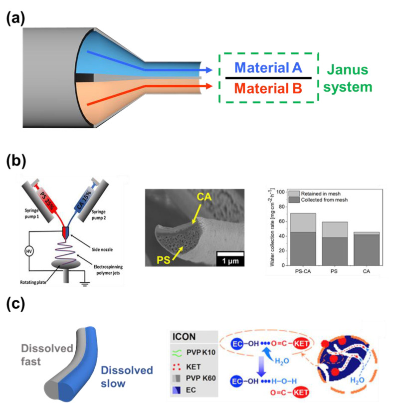
The purpose of the side-by-side double nozzle is to fabricate a Janus interface material (Janus system), where the two materials with different wettability are attached to each other (Figure 7a). The electrospinning nanofiber now has both the advantage of a Janus system, and the introduction of excellent surface area of nanofibers structure to the potential application [129]. On the downside, the two polymer solutions leave the nozzle near each other, not as one. There is the chance that they will be drawn into the collector separately, and form two separate fibers. Both the feeding rate and the voltage applied to the nozzle need to be well controlled.
Knapczyk–Korczak et al. introduced Janus nanofibers constructed from PS and CA using side-by-side nozzle electrospinning (Figure 7b) [130]. In the water harvesting application, the nanofibers with extraordinarily high surface area greatly improved the water collection rate of the membrane material. The hydrophilic material can collect the water molecule effectively, yet the water droplet needs to overcome the resistance to fall off the surface [131]. The proposed Janus material constructed from a hydrophobic (PS) and a hydrophilic (CA) can collect the water droplet, and continuously drain away the water to the collector. On the other hand, the Janus nanofibers were used by Yu et al. as the base material for the delivery of drugs to multi-location (Figure 7c) [132]. By changing the composition of the load materials, the authors could control the time it took for the polymer matrix to dissolve in the aqueous environment. In these Janus fibers, the PVP side was dissolved quickly together with the drug when in contact with water. Ethyl cellulose (EC) was added to the PVP on the other side of the fibers to prolong the dissolving time, thereby allowing the drug to be released in the second location. However, because EC cannot be dissolved, a small percentage of the drug was trapped, and could not be released.
Figure 7.
(a) Janus system created by electrospinning system using side−by−side nozzle. (b) Janus nanofibers consist of PS can CA, which was able to increase the efficiency in water harvesting [130]. Copyright 2021, American Chemical Society. (c) The different dissolve rates between the two sides of Janus nanofibers for drug delivery to multiple locations [132]. Copyright 2016, Elsevier.
2.2.4. Multiple Nozzle
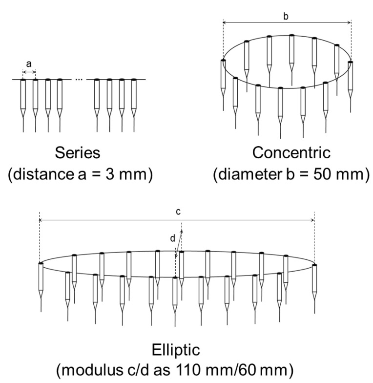
In industrial production, multiple nozzles and nozzles with less electrospinning can be used to increase the production rate, but excellent control is required for the uniformity of the nanofibers [133,134]. Multiple-nozzle electrospinning is an approach to enhancing the production rate of nanofibers. The working mechanism is based on traditional single-nozzle electrospinning but uses a combination of nozzles arranged according to specific geometries. The interaction between similarly charged jets from multi-nozzle electrospinning causes a repulsive phenomenon, leading to uneven fiber deposition and impacting the quality of the produced nanofibers. The repulsion phenomenon can be solved by increasing the distance between nozzles, so various configurations of multi-nozzles have been studied [135]. Tomaszewski et al. suggested three types of multi-jet electrospinning heads, including series, elliptic, and concentric. Among them, the concentric electrospinning head turned out best in both the efficiency and quality of the process (Figure 8) [136]. In addition, the drafting effect of the electric field force plays a key role in the formation of nanofibers. Then, Angammana et al. conducted a study about the correlation between the arrangement and the strength of the electric field [137]. They indicated that field distortion at each needle tip increases with the addition of needles. Furthermore, for the multi-nozzle electrospinning process to proceed smoothly, a higher voltage than usual must be used due to the large mass of the spinning solution delivered [138].
Figure 8.
Some types of multi-jet electrospinning heads, with a is the distance between nozzle in series, b is the diameter of concentric, and c/d are modulus of ellipse alignment [136].
In addition to enhancing the fiber production rate, the multiple-nozzle system makes it possible to fabricate fibers from different materials simultaneously [139]. However, despite the efforts to improve multi-jet electrospinning that have been made, electrostatic field interactions between the needles and needle clogging are still the limits of this technique.
2.2.5. Nozzle-Less
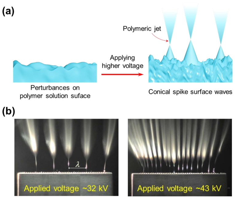
To address some drawbacks of nozzle-based electrospinning systems, nozzle-less electrospinning has been developed. Theoretically, the polymer jets of this system are generated by an external force (high voltage) added to create perturbances and obtain conical spike surface waves like Taylor cones [140]. A nanofiber web can be created once the polymeric jets have reached a conductive collector (Figure 9a). It should be noted that the concentration of electric force on the solution surface is a crucial issue for needleless electrospinning. The influence of the electric field on polymeric jets was demonstrated by Lukas et al. (Figure 9b) [141]. With the increase in voltage, the number of jets produced will increase. In addition, the nozzle-less electrospinning systems are sensitive to various parameters, such as the surface tension of the polymeric solution, the distance between the collector and the solution surface, etc. There are numerous needleless electrospinning architectures that have been designed, which focus on solution reservoirs, rotating spinnerets, syringeless, and so on [142,143].
Figure 9.
(a) Schematic illustration of multi-jet formation process on the free liquid surface. (b) The influence of the electric field on the number of polymeric jets [141]. Copyright 2008, AIP Publishing.
By loading extremely high voltages on the free liquid surface, numerous jets can be obtained simultaneously, which means a high production capacity can be achieved in the nozzle-less electrospinning technique. Moreover, obstacles caused by nozzles are absent in this system, like electrospinning of colloidal suspensions or needle clogging [144]. However, the relatively complex setup, applied high voltage, and hard-to-produce advanced nanofiber structures are still disadvantages. In addition, further studies need to be conducted on the fiber quality control and electrospinning processes before they reach industrialization and commercialization.
2.3. Collector
2.3.1. Planar Collector
Planar is the simplest structure of a collector, where a metal plate is used as a collector. Though the structure is simple, most of the fibers can be collected without the loss of material. The collected fibers are arranged in random directions. However, there are situations where the fibers are swollen. In this case, a large amount of solvent is hard to vaporize during the spinning process, which can be caused by the environmental condition, or the component of the electrospun solution. The remaining solvent pulls the surrounding polymer materials together and slowly dissolves them. To overcome this limitation, another type of collector has been developed.
2.3.2. Rotational Collector
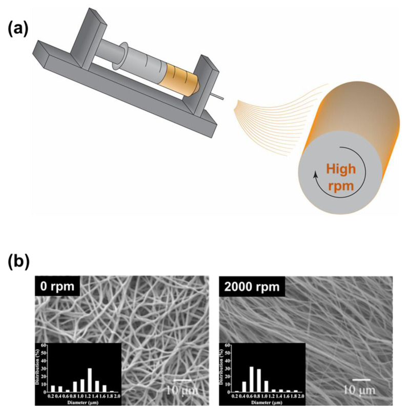
The rotational collector (drum-type collector), whose working mechanism is similar to that of a winder machine, can be used to collect the electrospun nanofibers (Figure 10a). The drum operates with a high-speed rotation to stretch the electrospun fibers, preventing their swelling. During the rotation, the air also circulates much better, thus the solvent evaporation rate was significantly improved. Thus, the drum collector can be used when it is difficult for the nanofibers to be collected by a planar collector. On the other hand, the nanofibers collected by the drum can be well aligned in one direction, whether it is intentional or not. Manuel et al. produced nanofibers for drug delivery with a drum-type collector (Figure 10b) [145]. The field emission scanning electron microscope (FE-SEM) figures indicate that the material was clearly highly aligned. However, the limitations of the drum-type collector come with the high-speed mechanical movement. Regular maintenance needs to be carried out more often to ensure the safety and stability of the rotation. Energy consumption for the drum is another issue that needs to be addressed, considering that the electrospinning operation already requires high power.
Figure 10.
(a) Electrospinning system with the rotational collector. (b) The well-aligned nanofibers collected by using a drum-type collector [145]. Copyright 2017, Elsevier.
2.3.3. Three-Dimensional Structure Collector
The nanofibers that were collected by the traditional planar collector can have a very random orientation. However, some of the advanced applications can have specific requirements for the structure of the membrane material. Many efforts have been made to align the electrospun nanofibers following a designed pattern.
Because of the limitation in aligning fibers using a drum-type collector, Tan et al. proposed a method to align the electrospun nanofibers using a 3D collector (Figure 11a) [146]. The study provided highly detailed information about the method to generate mono-directional aligned nanofibers for tissue engineering. Instead of using a single planar collector lining on the ground, two conducting collectors were placed in a V shape. Knowing that the collector position can be an important factor in the study, the collectors were assembled at two angles of 45° and 60°. The results from the 45° collector showed better control over the orientation of the nanofibers. The orientation of the nanofibers only concentrated around the angle of 90° at the specific height of 7.7 mm from the bottom of the collector. However, because the electrospun material did not stack on top of each other, the interaction between the nanofibers was reduced. The potential to be gathered as a membrane for use in other applications may be put into question.
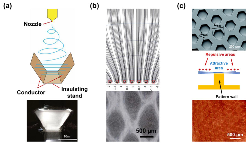
It was declared that topography is still one of the most critical conditions for cell culture, especially stem and bone tissues [147]. To date, chips have been fabricated using very effective photolithography, etching, or molding techniques. However, to mimic the in vivo extracellular matrix, which is constructed from nanofibers composite, Zhao et al. electrospun and aligned the nanofibers following the designed pattern with the 3D pattern collector (Figure 11b) [148]. The authors investigated the interaction between the conducting and non-conducting layers in the patterned collector. The non-conducting layer created a repulsive force, while the conductive layer created an attractive force towards the nanofibers. By patterning the layers, repulsive and attractive areas can be designed, and the resultant is the pattern of the nanofibers membrane. Furthermore, a single 3D conducting patterned collector was used by Nedjari et al. to make the electrospun nanofibers align following a pattern (Figure 11c) [149]. Though there is no non-conducting area on the pattern, attractive and repulsive areas can still be formed. The electrospun nanofibers leave the nozzle carrying electric charges, but the charges are released when making contact with the attractive pattern wall of the collector. The nanofibers that cannot make direct contact with the collector still have the changes, thereby creating repulsive forces in the valley between the walls. As a result, the latter electrospun nanofibers are only concentrated on the top of pattern walls. The developed method is easy to execute, but as the membrane becomes thicker, the repulsive area is less effective. Thus, the thickness of the fabricated membrane seems to be limited.
Figure 11.
(a) Three-dimensional collector for the collection of the one-direction aligned nanofibers [146]. Copyright 2018, Springer. (b) Nanofibers align following the pattern created by conducting and non-conducting layers of collector [148]. Copyright 2013, Royal Society of Chemistry. (c) Three-dimensional conducting collector with a pattern wall, which created an attractive force for the alignment of nanofibers [149]. Copyright 2015, Royal Society of Chemistry.
2.3.4. Bath Type Collector
Though most of the nanofibers should be collected in a dry environment, there are some exceptions. In some cases, the electrospun nanofibers can be collected in a bath collector containing liquid base material.
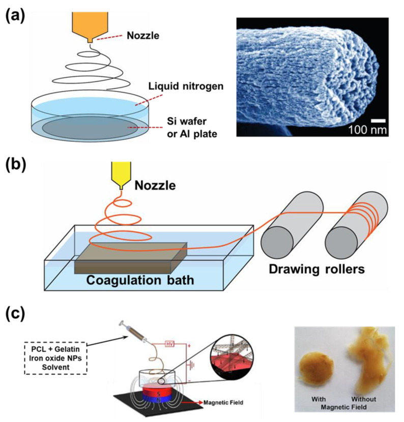
Many methods have been proposed to generate porous structures for the polymer fibers. However, these methods usually require sacrificial materials, but the removal of the sacrificial materials can also affect the main materials. McCann et al. electrospun a PAN solution directly into a bath of cryogenic liquid (nitrogen liquid) to create highly porous PAN nanofibers (Figure 12a) [150]. Before the solvent evaporated, the temperature of the polymer suddenly dropped lower than its glass transition temperature. The cool environment separates the polymer-rich and solvent-rich phases from each other, which is the driving force forming the polymer porous nanofiber. Thereafter, the polymer nanofibers need to warm up rapidly in the air to stabilize the fibers.
Figure 12.
(a) The porous PAN nanofibers created by quickly freezing the newly electrospun fibers with liquid nitrogen [150]. Copyright 2006, American Chemical Society. (b) The electrospinning of poly amid 6/66 into a water bath, which was later collected with drawing rollers [151]. Copyright 2018, Springer. (c) The nanofibers contain iron oxide nanoparticles for easy collection from water baths using a magnetic bar [152]. Copyright 2022, Elsevier.
A variation of electrospinning is sol–gel electrospinning, where the nanofibers still hold solvents inside the fibers. One example of sol–gel electrospinning was when the poly amid 6/66 (dissolved in formic acid and acetic acid) was used as the material. To overcome the limitation, Franco et al. spun the nanofiber directly into a bath containing distilled water (Figure 12b) [151]. The solvent was freed from the polymer matrix by the dispersion of solvent into the water, which can occur at a much higher rate than evaporation. Because the solvent was suddenly removed from the nanofibers, the solid polymer nanofibers have a porous structure, even though the porosity seems to be small. Finally, the electrospun fibers have to be collected by a drawing roller system. The difficulty in collecting the fibers from the water bath brought many limitations in application. However, it is undeniable that the wet electrospinning technique can create distance between the layers of nanofibers. This structure can offer many advantages. For example, in the studies of tissue engineering, it allows the cells to penetrate and migrate. Bakhtiary et al. introduced a method to use a magnetic field to collect the nanofibers in a water bath (Figure 12c) [152]. The author mixed superparamagnetic iron oxide nanoparticles into the polymer solution. Under a magnetic field, the nanofibers containing particle material were drawn towards the magnetic bar placed under the bath. After freeze-drying, aerogel-like material could be collected, and later used for cell seeding.
2.3.5. Electrode-Assisted Collector
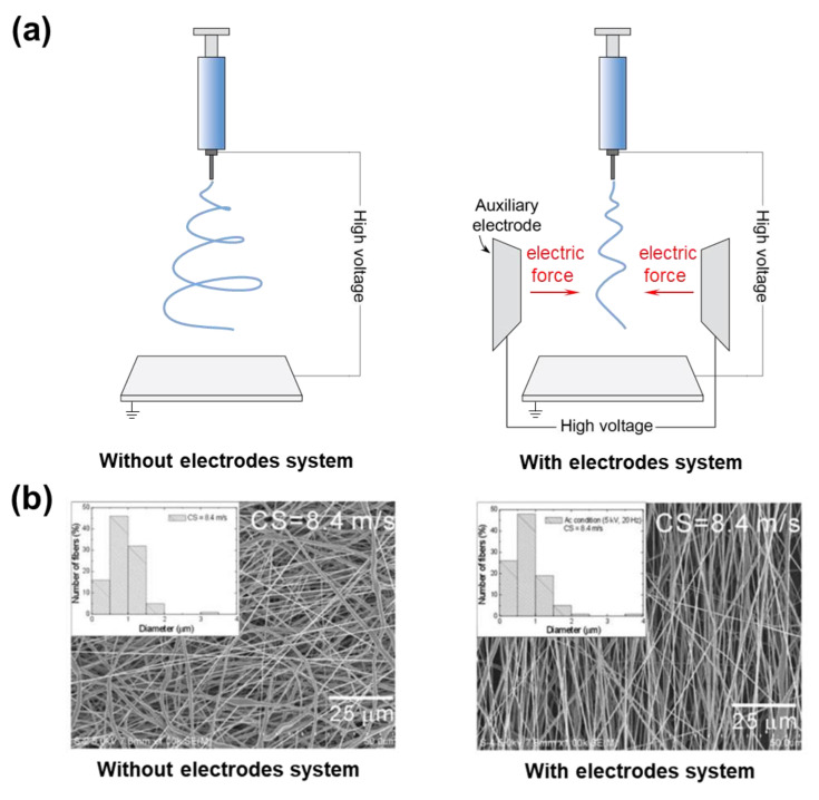
To intensify the electric field and enhance jet stabilization in the electrospinning system, auxiliary electrodes are employed, which control the deposition and diameter of electrospun nanofibers [153]. Ring, cylindrical, and plate are the most popular shapes of auxiliary electrodes. Normally, the auxiliary electrodes are added between the needle and collector and carry a similar polarity to the needles (Figure 13a). By increasing the applied potential of electrodes, the electrospinning jet is narrowed, limiting the area of fiber deposition. In addition, many researchers have studied the aspect of materials, type of polarity, type of supplied power (AC or DC), and location of the electrodes in the set-up to obtain the fiber morphology that meets the needs of the final application [154]. Moreover, it is possible to control fiber orientation and obtain aligned fibers by modification of the collector of this electrospinning system. For instance, by using a rotating collector and adjusting its surface speed, highly aligned polymer fibers can be obtained [155] (Figure 13b).
Figure 13.
(a) Schematic illustrates the bending instability of a polymer jet with and without auxiliary electrodes. (b) The fiber deposition onto a rotating collector with and without auxiliary electrodes [155]. Copyright 2009, Springer.
2.3.6. Magnetic Field-Assisted Collector
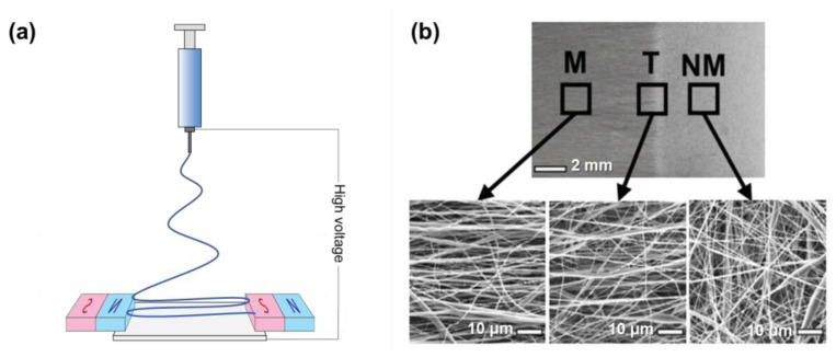
Other than the electric field derived from auxiliary electrodes, a magnetic field derived from permanent magnets can also be used to assist the electrospinning to produce highly aligned fibers. The most common setup is a pair of permanent magnets installed between the collector of the conventional electrospinning with no direct contact between them (Figure 14a). When the whipping jet approaches the collector, under the influence of the magnetic field, it is stretched and aligned across the magnets [156]. To enhance the spatial control ability and fiber morphology, several parameters of magnetic field-assisted electrospinning have been investigated, including magnet geometry, voltage, magnetic nanoparticle presence in the polymer solution, and flow rate [157]. Recently, magnetically assisted electrospinning allowed precise spatial control over electrospun fiber alignment for fabricating musculoskeletal interfacial tissues that have complex gradient structures. Here, the collector was designed with three regions that have different magnetic properties, including magnetic (M), non-magnetic (NM), and transition (T) (Figure 14b) [158]. As a result, electrospun fibers were highly aligned in a magnetic field and randomly aligned within the non-magnetic region. It is also indicated that magnetic field-assisted electrospinning is possible for spatial control over fiber alignment, even at sub-millimeter resolution, showing a bright future for this method in tissue engineering.
Figure 14.
(a) Schematic illustrates the magnetic field-assisted electrospinning system for preparing aligned nanofibers. (b) Electrospun fiber alignment in magnetic field (M), transition (T), and non-magnetic (NM) region [158]. Copyright 2023, Wiley.
2.4. Other Technical Factors
2.4.1. Distance from the Nozzle and the Collector
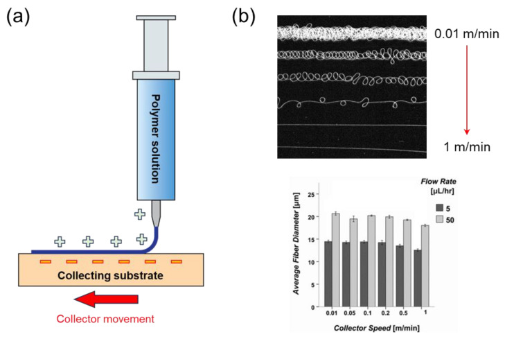
Nearfield electrospinning was designed to completely overcome the shortcomings in random nanofibers generated by traditional electrospinning systems. Here, the distance between the nozzle and the collector is dramatically reduced (Figure 15a). It was suggested to be maintained from 0.5 to 3 mm [159]. Instead, the nozzle or collector can be mobilized enabling the ability to be deposited over long distances, which is similar to the 3D printing technique. This speed plays an important factor in the operation of the near-field electrospinning in addition to the mentioned parameter. As the movement speed becomes faster, the generated nanofibers will be stretched into a single straight fiber (Figure 15b) [160]. These fibers can be deposited following a designed location. Despite the limitation in the slow production rate of near-field electrospinning, excellent accuracy in orientation provides potential in the application of nanodevice materials. For instance, well-oriented nanofibers can greatly contribute to controlling pore size, which is highly required in cell cultivation [161].
Figure 15.
(a) Near-field electrospinning system and (b) the effects of flow rate and collector movement speed on the deposition of electrospun nanofibers [160]. Copyright 2011, Wiley.
2.4.2. Applied Voltage Types
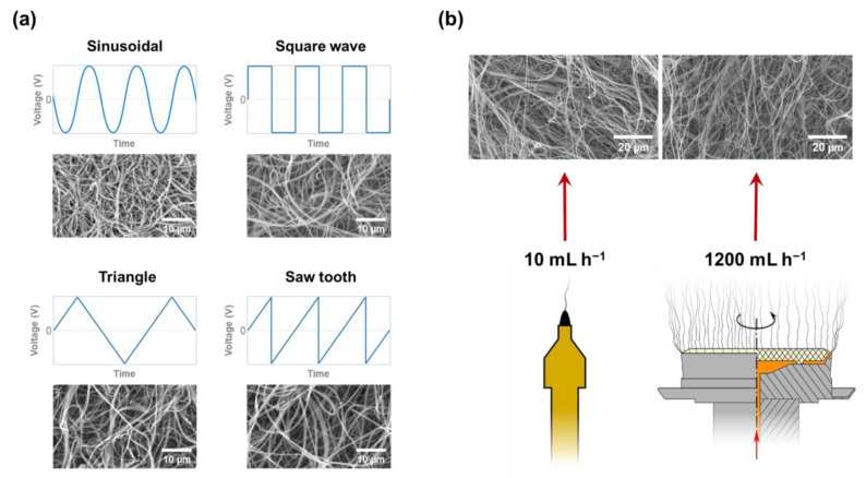
Traditionally, the electrospinning technique has utilized direct current (DC). However, during the development of the electrospinning technique, alternating current (AC) was applied to limit the accumulation of electrical charge on the collected nanofibers. Here, the frequencies and waveforms of AC used for the electrospinning process were proposed in Figure 16a [162]. No clear differences can be detected from SEM images, whether in fiber diameter or uniformity. However, the efforts to vary the polymer concentration and feeding rate cannot fully overcome the limitation of AC electrospinning, which produces nanofibers with poor quality, large beads, and droplets. Here, the electrical conductivity of the solution can be considered a decision role to overcome this limitation. For instance, Farkas et al. investigate the contribution of polyvinylpyrrolidone K90 (PVPK90) and electrical conductivity, which is controlled by the amount of sodium dodecyl sulfate, to the stability of electrospun nanofiber formation (Figure 16b) [163]. Not only that, once the nanofibers can be generated uniformly from the electrospinning, the feeding rate can be increased up to 1200 mL h−1. Such high feeding rates open up the potential for electrospinning techniques on an industrial scale.
Figure 16.
(a) The nanofibers generated from electrospinning using different waveforms of AC [162]. Copyright 2020, Elsevier, and (b) the stability in nanofibers formation in high feeding rate of AC electrospinning using large size rotating nozzle [163]. Copyright 2019, Elsevier.
3. Applications
Electrospinning can produce outstanding candidate materials for a wide range of applications. However, there are many applications where the enhanced performance can be carried out by the modification in nanofibers morphology are few in number. Some of the representative applications can be named including air purification, sound absorption, heat retention, etc. [164,165,166,167,168,169,170]. Their development rather lies in the interactions between the fibers with each other to build the membrane network. On the other hand, electrospun nanofibers whose morphology has been modified have been proven to be able to provide suitable active sites for the operation of the following applications: oil/water separation, drug delivery, tissue engineering, etc. [171,172,173].
The after-treatment of the electrospun nanofibers also opens up the potential for more advanced applications. The most popular treatment is the carbonization process at high temperatures. There, electrospun nanofibers are converted into materials with different compositions depending on the carbonization conditions. The conditions that contribute to the properties and structure of the outcome material are the electrospun solution component, carbonized temperature, environment, and heating rate. While the polymer can act as the precursor that is converted into carbon material, it can also serve as the template for the structure formation of metal or metal oxide. Though the high surface area of the product nanofibers can improve the performance in the application by prioritizing the interaction between the active material and the working environment, their low physical properties limit their use in the mentioned applications. Instead, excellent electrical conductivities make them ideal materials for the development of applications involving electrochemical activities [24].
3.1. Oil/Water Separation
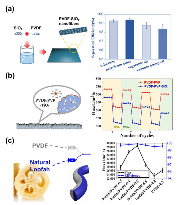
Oil/water separation is important for the protection of the environment from oil pollution and its deleterious effects [174]. Due to its facile process and various structural designs, the electrospun fiber membrane is considered a good material for the application of oil/water separation. These modifications mainly focus on improving the interaction between the surface of nanofibers and the surrounding environment. Loading inorganic nanoparticles into the hydrophilic polymer can greatly improve the hydrophilicity of the filter membrane. Jiang et al. manufactured an effective oil/water separation membrane through a one-step electrospinning process using a poly(vinylidene fluoride)-silica (PVDF−SiO2) blend solution (Figure 17a) [175]. The SiO2 nanoparticles also provide a rough surface to PVDF nanofibers, which increases the solid–liquid contact area, leading to higher geometric hydrophobicity. Because of the hydrophobic SiO2, the PVDF−SiO2 nanofibers membrane has super-hydrophobic and super-lipophilic properties, when compared to the pure poly(vinylidene fluoride) (PVDF) fibers. Consequently, the PVDF−SiO2 nanofibers exhibited a separation flux of 2963 L·m−2h−1 and a separation efficiency value of 99.4%, which indicates its suitability for use for oil/water separation. Du et al. represented a functional separation membrane through a one-step electrospinning method. They produced a PVDF/PVP−TiO2 hydrophilic nanofiber membrane by using a blend solution (Figure 17b) [176]. While PVDF as a base material can provide good mechanical strength and chemical resistance, PVP assists the hydrophilicity of the TiO2. The TiO2 allows membranes to have self-cleaning ability, pollution prevention, and antibacterial properties. Membranes of the three ingredients showed high separation efficiency for n-hexadecane, petroleum ether, and edible oil. Likewise, the PVDF/PVP−TiO2 nanofiber fulfilled high oil–water separation and anti-fouling properties.
Figure 17.
(a) The fabrication of PVDF-SiO2 nanofiber membrane and its application in oil–water separation [175]. Copyright 2020, Wiley. (b) Fabrication procedure of PVDF/PVP-TiO2 hydrophilic filter through one-step electrospinning method [176]. Copyright 2021, Elsevier. Copyright 2022, Elsevier. (c) Core–shell structure of loofah–PVDF membrane and its oil–water separation behavior [177]. Copyright 2020, American Chemical Society.
In another example, Wang et al. produced a switchable oil–water separation membrane based on natural loofah and PVDF through side-by-side nozzles (Figure 17c) [177]. The difference in surface tension between the PVDF and loofah solution provides the driving force to form a core–shell structure. The natural loofah/PVDF nanofibers behave especially as a switchable oil/water separator that allows oil separation in dry conditions, and water separation in wet conditions. As such, the PVDF/loofah-based Janus membrane produced by side-by-side nozzles effectively achieves a core–shell structure for effective oil/water separation.
3.2. Tissue Engineering
Tissue engineering, known as regenerative medicine, has in recent years been developed rapidly as an effective treatment method for tissue injuries by providing the appropriate physiological microenvironment. One of the most important components of tissue engineering is the scaffold that supports the growth of cells and provides a vector that delivers the biochemical factors [178]. Because the different properties can be found in different kinds of tissue, the requirements of the scaffold can also be highly specific. In addition to the high porosity and the ability to be aligned, the wide choices of materials allow the electrospinning of nanofiber products with a diversity of properties. Therefore, electrospinning can be considered a powerful tool to manufacture scaffolds for tissue engineering.
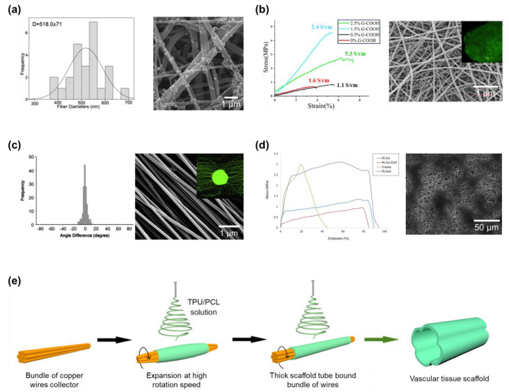
In bone tissue engineering, the prioritized properties of the scaffold are the high porosity and mechanical properties of the membrane. Since electrospun nanofibers can construct a membrane with extraordinarily high porosity, fillers can be added to the nanofibers to improve their mechanical properties. In addition to the polyhydroxybutyrate (PHB) matrix in the nanofibers, Toloue et al. added chitosan and alumina nanowires as the filler for the nanofibers (Figure 18a) [179]. The composite nanofibers have their physical strength significantly improved, which makes them suitable to act as scaffolds for bone tissue engineering. The fillers also help stabilize the nanofibers in the aqueous environment, preventing the structure of nanofibers from collapsing during the construction period of tissue. For use in cardiac tissue engineering, the scaffold built from electrospun nanofibers must have good electrical conductivity and elasticity to mimic the cardiac function. Talebi et al. proposed the composite nanofibers built of a network of polycaprolactone, chitosan, and polypyrrole (Figure 18b) [180]. The membrane fibers have good electrical conductivity thanks to the graphene and polypyrrole segments. As more graphene was introduced into the material, the electrical conductivity was also enhanced. The scaffold material with more graphene contained also expresses outstanding mechanical strength, suitable to be applied in the application of cardiac tissue development. However, the amount of graphene filler being higher than 1.5% can significantly reduce the mechanical properties. In the scaffold for nerve tissue engineering, physical strength is no longer a priority. Here, the alignment of nanofibers needs to be the focus of attention. The alignment of the nanofibers in the membrane can guide the neurite extension through a lesion site for regeneration. Biocompatible PLA nanofibers were aligned following a single direction by Wang et al. (Figure 18c) [181]. The authors showed the positive effect of nanofiber alignment over the culture of nerve tissue and also presented the influence of the diameter of the fibers. On the other hand, the development of scaffolds for skin engineering should be considered angiogenesis, gas exchange, moisture maintenance, and the mass transport of tissue. Therefore, while electrospinning can provide a membrane constructed from nanofibers that have suitable properties, the scaffold still needs to have physical properties that match that of the native skin tissue, especially the high stretchability. Norouzi et al. used the hybrid between poly(lactic-co-glycolic acid) and gelatin as material for electrospinning (Figure 18d) [182]. The fibers could later be collected as a stretchable membrane (up to 90%) that can be used in skin tissue engineering and wound dressing. Until now, many efforts have been carried out to mimic vascular tissue. However, its own structure resembling a small diameter hollow tube is the biggest challenge that needs to be overcome. However, electrospinning can overcome such small size fabrication by reducing the diameter of the rotated drum collector. The well-oriented nanofibers can provide a suitable scaffold for the cultivation of vascular cells. However, one issue that remains during the production of electrospun scaffolds is that the removal of nanofibers can damage the microstructure. To overcome the limitation, Mi et al. modified the collector into a bundle of copper wires as demonstrated in Figure 18e for the fabrication of a tube scaffold [183]. When the rotating speed increased during the operation of the electrospinning system, the centrifugal force made the satellite copper wires expand affecting the initial diameter of the tube. Thereafter, the thickness of the tube bound the wire collector and created a wavy configuration on the inner layers. The reported nanofiber tube not only be easily collected, but its structure is also similar to the zero stress state of the blood vessel.
Figure 18.
(a) High physical properties nanofibers for the scaffold of bone tissue engineering [179]. Copyright 2019, Elsevier. (b) Electrical conducting nanofibers as the scaffold of cardiac tissue engineering [180]. Copyright 2020, American Chemical Society. (c) Well-aligned nanofibers as scaffold for nerve tissue engineering [181]. Copyright 2010, Elsevier. (d) Highly stretchable electrospun membrane as scaffold of the skin tissue engineering [182]. Copyright 2014, Wiley. (e) Bundled copper wires collector for the fabrication of vascular tissue scaffold [183]. Copyright 2018, Elsevier.
3.3. Supercapacitor
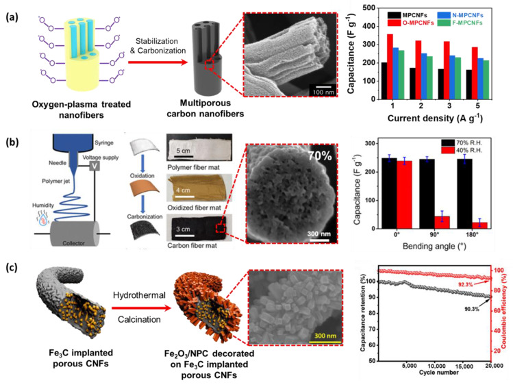
Supercapacitors could improve performance by varying the morphology of electrospun nanofibers. In particular, porous carbon nanofibers are actively studied to maximize the supercapacitor performance due to their high surface-to-volume ratio with the electrolyte, thereby efficiently transporting electrons in the longitudinal direction. For instance, Nam et al. electrospun the solutions using mixed PAN and PS to obtain polymer nanofibers (Figure 19a) [184]. During carbonization, PS is used as a sacrificial substance to generate pores inside the multiporous carbon nanofibers. The carbon material has a high-capacity value of 202.4 F·g−1 at a current density of 1 A·g−1. Moreover, to improve the capacitance performance, introducing heterogeneous elements to the CNF’s surface by oxygen plasma treatment was conducted. As a result, the capacity value is enhanced more than 1.5 times the non-plasma-treated CNFs (358.2 F·g−1 at 1 A·g−1). In another approach, Serrano et al. developed a strategy to generate flexible porous CNFs derived from electrospun PMMA-block-PAN copolymers nanofibers (Figure 19b) [185]. The porous carbon fibers (PCFs) have different shapes depending on humidity due to the vapor-induced phase separation. Therefore, electrical double-layer capacitance and flexibility were effectively achieved at an intermediate range of 70% RH, showing 249 F·g−1 capacitance value and 97.3% cycling stability. In an effort to further improve the supercapacitor performance, Acharya et al. are attracted by the moderated thermal transformation ability of metal−organic frameworks (MOFs), which empowers the synthesis of nanomaterials with precisely controlled porosities and morphologies (Figure 19c) [186]. Here, iron MOF and MIL-88A were used as the source of Fe2O3/nanoporous carbon (NPC) and Fe3C, respectively. Through electrospinning using a mixed solution of MIL-88A, PMMA, and PAN, following hydrothermal treatment and carbonization to obtain Fe2O3/NPC decorated on Fe3C implanted porous carbon nanofibers. The resulting MOF-derived electrode materials exhibit a high specific capacitance of 531 F·g−1 at 1 A·g−1. It is worth noting that porosity plays an important role in enhancing supercapacitor performance, and highly porous supercapacitor electrode materials can simply be obtained using an electrospinning system.
Figure 19.
(a) The oxygen-plasma-treated multiporous CNFs showed the highest capacity value compared with other ones [184]. Copyright 2023, MDPI. (b) The PMMA−PAN fibers under a relative humidity of 70% and its gravimetric capacitance [185]. Copyright 2022, American Chemical Society. (c) Tetragonal rod-like nanomaterials interconnected with carbon nanofiber surfaces used as super-capacitor electrodes exhibited high specified capacitance [186]. Copyright 2023, American Chemical Society.
3.4. Battery Electrode
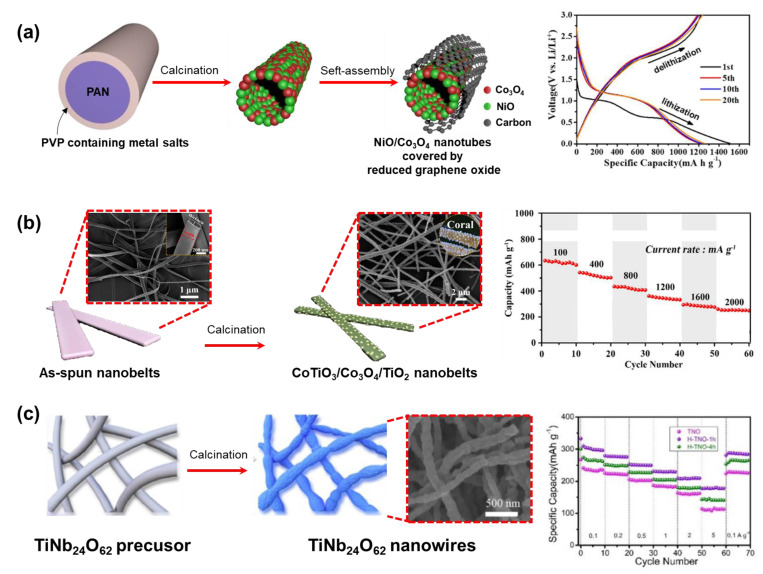
Since the early years of the 21st century, researchers have believed that to improve the capacity of lithium batteries, the graphite anode should be replaced by another anode material that has a relatively small molecular weight, low density, a favorable stoichiometric ratio for accepting Li, and higher retention ability during repeated charge–discharge cycles [187]. Metal oxide (MO) has emerged as an ideal material to replace graphite because of both its superior capacity and its low cost and facile synthesis [188,189]. However, the naturally poor electrical conductivity and resistance to pulverization during lithiation/delithiation remain challenges. To address these issues, experts approached the electrospinning technique to fabricate metal oxide nanofibers [190]. Cobalt oxide (Co3O4) and nickel oxide (NiO) nanofibers were obtained as alternative anode materials through a similar process [191,192]. However, their capacity and retention are still insufficient to meet the demand for large-scale applications. The combination of metal oxides opened a new orientation towards improving anode materials due to the abundant electrochemical activities, more redox reactions, and especially the synergistic effect between two different metals. For example, Dai et al. designed an anode for lithium-ion batteries with NiO/Co3O4 nanotubes encapsulated with reduced graphene oxide using an electrospinning technique (Figure 20a) [193]. As a result, the anode showed large lithium-ion storage capability (~1206 mAh·g−1 at 0.1 A·g−1 after 100 cycles), and high-rate capacity and cycle stability. Here, the reversible reaction of the lithium-ion with NiO and Co3O4 (conversion-type capacity), the pore of the tubular structure, and the surface of reduced graphene oxide (adsorption-type capacity) all contribute to the specific capacity. Another interesting case is Liu et al.’s fabrication of lithium-ion batteries anode from one-dimension hierarchical coral-like CoTiO3/Co3O4/TiO2 hybrid nanobelts via a two-step electrospinning calcination strategy (Figure 20b) [194]. This electrode material offers a combination of advantages from metal components (CoTiO3 (enhancing cyclic stability), Co3O4 (high theoretical specific capacity), and TiO2 (improvement of structural stability)), and all advantages are reflected in the electrochemical performance (capacity of 722.3 mAh·g−1 at 100 mA·g−1 after 250 cycles). Moreover, the unique coral-like nanobelt structures benefit the lithium ions transformation, and then provide excellent support for the specific capacity.
One group that cannot be ignored in the family of alternative anode materials is the intercalation-type metal oxide materials (e.g., Li4Ti5O12, CuFe2O4, ZnCo2O4, and TiNb24O62) which are well-known for their low-toxicity, reduction total cost, and tunability of working voltage and energy density by varying the metal ratio [195,196,197]. However, like other metal oxide groups, this material must have a tailored design in the nanostructures to shorten the dispersion distances of lithium ions and enhance the specific capacity. For example, instead of using solvent–thermal or template methods (which are complex and require additional templates) to generate TiNb24O62 porous nanoparticles, Zhu et al. used simple electrospinning with a subsequent hydrogenation method to create the material in the form of a one-dimensional nanowire with lots of oxygen vacancies (Figure 20c) [198]. As expected, the designed material exhibits a faster lithium-ion diffusion path and more pseudo-capacity behavior activity than the bulk material. The electrospinning technique can be seen to have played a significant role in enriching the structural morphology and improving the electrochemical performance of lithium-ion batteries.
Figure 20.
(a) High-rate capacity and cycle stability of anode made from NiO/Co3O4 nanotubes encapsulated with reduced graphene oxide wall [193]. Copyright 2020, American Chemical Society. (b) The unique coral-like CoTiO3/Co3O4/TiO2 hybrid nanobelts structures anode benefits the lithium ions transformation and provides excellent support for the specific capacity [194]. Copyright 2019, Wiley. (c) TiNb24O62 porous nanowires have lots of oxygen vacancies providing more pseudo-capacity behavior activity for the anode [198]. Copyright 2021, Elsevier.
3.5. Chemical Sensor
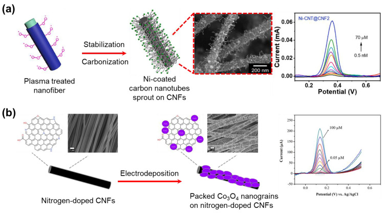
Electrochemical sensors enable the export of electrical signals produced by interactions between the analytes [199]. The material of electrochemical sensors could be obtained by attaching metal or metal oxide to the surface of CNFs. Phan et al. report a strategy to generate nickel-decorated multidimensional CNFs via electrospinning combined with oxygen plasma treatment and carbonization (Figure 21a) [200]. Here, nickel particle-coated carbon nanotubes sprout on the surface of the CNFs through the catalytic reaction of nickel and decomposed PVP during the carbonization. This creates a large active surface area supporting rapid electron transfer leading to effective electrochemical detection. As a result, this CNFs-based electrochemical sensor has a high sensitivity (25.29 μA·μM−1 cm−2 for 0.027 cm2 active surface area) and a low limit detection (0.5 nM) to acetaminophen molecules. Based on facile electrospinning and electrodeposition, Yin et al. fabricated packed cobalt oxide nanograins on nitrogen-doped CNFs to assemble a dopamine electrochemical sensor (Figure 21b) [201]. The high surface area of the carbon nanofiber matrix and the homogeneous dispersion of Co3O4 led to effective dopamine detection. In addition, the carbon skeleton supports electron transfer within the electrode surfaces. This sensor showed a low limit detection (9 nM) over a wide range of concentrations of (0.01 to 100) µM, superior sensitivity, and excellent selectivity for dopamine detection.
Figure 21.
(a) Nickel-decorated multidimensional CNFs applied in acetaminophen detection [200]. Copyright 2023, Elsevier. (b) Cobalt oxide nano-grains on nitrogen-doped CNFs applied in dopamine detection [201]. Copyright 2022, Elsevier.
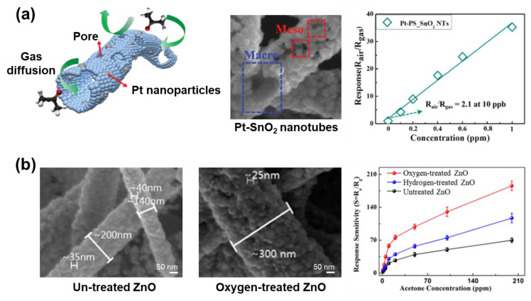
In recent years, attention to electrospinning metal oxide nanofibers in gas sensing applications has increased due to their unique structures and good electrical properties [202]. Needless to say, the unique morphology facilitates the efficient penetration of the target gas into the active metal oxide layer, which is the main reason for the high sensitivity of metal oxide gas sensors. Another approach to enhance sensor performance is to use noble metals to decorate metal oxide nanofibers. Using electrospinning combined with the calcination process, Jang et al. easily decorated Pt homogenous catalyst carriers on porous SnO2 nanotubes (Figure 22a) [203]. Here, PS was added into the electrospun solution as a sacrificial template to generate meso- and macro-pores on material structure. Moreover, noble metals dispersed in the material work as effective catalysts by decreasing the activation energy of gas chemisorption. These two metrics create a synergistic effect to significantly improve the selectivity and sensitivity of the sensors. In detail, the sensor showed superior selectivity against other interfering gases (including H2S, toluene, pentane, CO, NO, NH3, CH4, and H2) and the capability of detecting low-level acetone (10 ppb). To induce a change in the surface of nanofibers, as well as the addition of a hetero-component to the as-spun solution, exposing the nanofiber to oxygen plasma also promotes an increase in the sensor’s response. For example, oxygen-plasma-treated ZnO nanofibers show excellent acetone-sensing properties, due to their specific surface area and porosity increase (Figure 22b) [204]. After plasma treatment, more pores and a larger specific surface area were achieved on ZnO nanofibers. Moreover, the bandgap of oxygen-exposed ZnO nanofibers significantly changed to near Fermi level, leading to charge transfer and further expansion of the charge depletion region [205]. As a result, ZnO nanofibers exposed to plasma oxygen gas exhibited an approximately two-fold increase in response sensitivity, compared to untreated nanofibers.
Figure 22.
(a) Pt acts as a catalyst contributing to enhanced selectivity and sensitivity of Pt porous SnO2 nanotubes [203]. Copyright 2016, Wiley. (b) Oxygen-plasma-treated ZnO nanofibers show excellent acetone-sensing properties over the untreated ones [204]. Copyright 2020, American Chemical Society.
4. Conclusions
Electrospinning is a method of manufacturing nanofibers. Though the materials for the electrospinning processes are usually polymer solutions, the treatments on the nanofibers and extensive choices of materials allow many kinds of materials to be produced. To date, the materials that can be provided by electrospinning include polymer, polymer composite, metal, and metal oxide nanofibers. On the other hand, modifications to the electrospinning system configuration can lead to various changes in the collected nanofiber membrane. Firstly, not only does the use of special nozzles and collectors alter the morphology of the electrospun nanofibers, but the combination of different solvents and materials in one single electrospun solution can also lead to the same results. Furthermore, the after-treatment carried out on the nanofibers can convert them into different materials. Especially carbon nanofibers, which have a significantly high surface area created from the removal of sacrificing materials, can be harvested from the carbonization of electrospun nanofibers. Secondly, the addition of extra parts, which are used to control the pathway of the electrical field, can align the nanofibers following a designed pattern. In short, there is no limitation in the morphology and alignment of nanofibers that can be produced by electrospinning, opening up the potential to be further developed in the future. However, the disadvantages of the electrospinning process are that it is highly dependent on the environment humidity and stability of the power source, restricting the use of the technique in specific conditions. The applications of these nanofibers were also introduced in the review. It is clear that the electrospun nanofibers have been used in many applications, from simple applications, such as sound absorption and air purification, to highly advanced applications, like sensors, catalysts, and energy storage. The electrospinning method has great potential to provide materials with excellent properties, while it also offers many opportunities for further improvement.
Acknowledgments
This work was supported by Gachon University Research Fund of 2023 (GCU- 202303890001).
Author Contributions
The manuscript was written through the contributions of all authors. All authors have read and agreed to the published version of the manuscript.
Data Availability Statement
Not applicable.
Conflicts of Interest
The authors declare no competing financial interests.
Funding Statement
This research received no external funding.
Footnotes
Disclaimer/Publisher’s Note: The statements, opinions and data contained in all publications are solely those of the individual author(s) and contributor(s) and not of MDPI and/or the editor(s). MDPI and/or the editor(s) disclaim responsibility for any injury to people or property resulting from any ideas, methods, instructions or products referred to in the content.
References
- 1.Tan E.P.S., Lim C.T. Mechanical characterization of nanofibers–A review. Compos. Sci. Technol. 2006;66:1102–1111. doi: 10.1016/j.compscitech.2005.10.003. [DOI] [Google Scholar]
- 2.Jayaraman K., Kotaki M., Zhang Y., Mo X., Ramakrishna S. Recent advances in polymer nanofibers. J. Nanosci. Nanotechnol. 2004;4:52–65. [PubMed] [Google Scholar]
- 3.Yoon K., Hsiao B.S., Chu B. Functional nanofibers for environmental applications. J. Mater. Chem. 2008;18:5326–5334. doi: 10.1039/b804128h. [DOI] [Google Scholar]
- 4.Wang M., Jin H.J., Kaplan D.L., Rutledge G.C. Mechanical Properties of Electrospun Silk Fibers. Macromolecules. 2004;37:6856–6864. doi: 10.1021/ma048988v. [DOI] [Google Scholar]
- 5.Revati R., Majid M.S.A., Ridzuan M.J.M., Nasir N.F.M. Characterisation of structural and physical properties of cellulose nanofibers from Pennisetum purpureum. IOP Conf. Ser. Mater. Sci. Eng. 2019;670:012043. doi: 10.1088/1757-899X/670/1/012043. [DOI] [Google Scholar]
- 6.Langwald S.V., Ehrmann A., Sabantina L. Measuring Physical Properties of Electrospun Nanofiber Mats for Different Biomedical Applications. Membranes. 2023;13:488. doi: 10.3390/membranes13050488. [DOI] [PMC free article] [PubMed] [Google Scholar]
- 7.Tan E.P.S., Lim C.T. Physical properties of a single polymeric nanofiber. Appl. Phys. Lett. 2004;84:1603–1605. doi: 10.1063/1.1651643. [DOI] [Google Scholar]
- 8.Kim H.J., Roy S., Rhim J.W. Effects of various types of cellulose nanofibers on the physical properties of the CNF-based films. J. Environ. Chem. Eng. 2021;9:106043. doi: 10.1016/j.jece.2021.106043. [DOI] [Google Scholar]
- 9.Long Y.Z., Li M.M., Gu C., Wan M., Duvail J.L., Liu Z., Fan Z. Recent advances in synthesis, physical properties and applications of conducting polymer nanotubes and nanofibers. Prog. Polym. Sci. 2011;36:1415–1442. doi: 10.1016/j.progpolymsci.2011.04.001. [DOI] [Google Scholar]
- 10.Suzuki T., Cheng J., Qiao L., Xing Y., Zhang M.F., Nishijima H., Yano T., Pan W. Preparation of SnO2 nanotubes via a template-free electrospinning process. RSC Adv. 2020;10:22113–22119. doi: 10.1039/D0RA01719A. [DOI] [PMC free article] [PubMed] [Google Scholar]
- 11.Subbiah T., Bhat G.S., Tock R.W., Parameswaran S., Ramkumar S.S. Electrospinning of nanofibers. J. Appl. Polym. Sci. 2005;96:557–569. doi: 10.1002/app.21481. [DOI] [Google Scholar]
- 12.Chen J., Yu Z., Li C., Lv Y., Hong S., Hu P., Liu Y. Review of the Principles, Devices, Parameters, and Applications for Centrifugal Electrospinning. Macromol. Mater. Eng. 2022;307:2200057. doi: 10.1002/mame.202200057. [DOI] [Google Scholar]
- 13.Nadaf A., Gupta A., Hasan N., Fauziya, Ahmad S., Kesharwani P., Ahmad F.J. Recent update on electrospinning and electrospun nanofibers: Current trends and their applications. RSC Adv. 2022;12:23808–23828. doi: 10.1039/D2RA02864F. [DOI] [PMC free article] [PubMed] [Google Scholar]
- 14.Xue J., Xie J., Liu W., Xia Y. Electrospun Nanofibers: New Concepts, Materials, and Applications. Acc. Chem. Res. 2017;50:1976–1987. doi: 10.1021/acs.accounts.7b00218. [DOI] [PMC free article] [PubMed] [Google Scholar]
- 15.Wang C., Wang J., Zeng L., Qiao Z., Liu X., Liu H., Zhang J., Ding J. Fabrication of Electrospun Polymer Nanofibers with Diverse Morphologies. Molecules. 2019;24:834. doi: 10.3390/molecules24050834. [DOI] [PMC free article] [PubMed] [Google Scholar]
- 16.Yang X., Wang J., Guo H., Liu L., Xu W., Duan G. Structural design toward functional materials by electrospinning: A review. e-Polymers. 2020;20:682–712. doi: 10.1515/epoly-2020-0068. [DOI] [Google Scholar]
- 17.Ghosal K., Augustine R., Zaszczynska A., Barman M., Jain A., Hasan A., Kalarikkal N., Sajkiewicz P., Thomas S. Novel drug delivery systems based on triaxial electrospinning based nanofibers. React. Funct. Polym. 2021;163:104895. doi: 10.1016/j.reactfunctpolym.2021.104895. [DOI] [Google Scholar]
- 18.Zhao J., Cui W. Functional Electrospun Fibers for Local Therapy of Cancer. Adv. Fiber Mater. 2020;2:229–245. doi: 10.1007/s42765-020-00053-9. [DOI] [Google Scholar]
- 19.Yan X., Xiao X., Au C., Mathur S., Huang L., Wang Y., Zhang Z., Zhu Z., Kipper M.J., Tang J., et al. Electrospinning nanofibers and nanomembranes for oil/water separation. J. Mater. Chem. A. 2021;9:21659–21684. doi: 10.1039/D1TA05873H. [DOI] [Google Scholar]
- 20.Mao X., Wang Y., Yan X., Huang Z., Gao Z., Wang Y., Huang L., Kipper M.J., Tang J. A review of superwetting membranes and nanofibers for efficient oil/water separation. J. Mater. Sci. 2023;58:3–33. doi: 10.1007/s10853-022-07945-8. [DOI] [Google Scholar]
- 21.Xie X., Li D., Chen Y., Shen Y., Yu F., Wang W., Yuan Z., Morsi Y., Wu J., Mo X. Conjugate Electrospun 3D Gelatin Nanofiber Sponge for Rapid Hemostasis. Adv. Healthc. Mater. 2021;10:2100918. doi: 10.1002/adhm.202100918. [DOI] [PubMed] [Google Scholar]
- 22.Nguyen T.D., Nguyen M.T.N., Lee J.S. Carbon-Based Materials and Their Applications in Sensing by Electrochemical Voltammetry. Inorganics. 2023;11:81. doi: 10.3390/inorganics11020081. [DOI] [Google Scholar]
- 23.Xue J., Wu T., Dai Y., Xia Y. Electrospinning and Electrospun Nanofibers: Methods, Materials, and Applications. Chem. Rev. 2019;119:5298–5415. doi: 10.1021/acs.chemrev.8b00593. [DOI] [PMC free article] [PubMed] [Google Scholar]
- 24.Chinnappan B.A., Krishnaswamy M., Xu H., Hoque M.E. Electrospinning of Biomedical Nanofibers/Nanomembranes: Effects of Process Parameters. Polymers. 2022;14:3719. doi: 10.3390/polym14183719. [DOI] [PMC free article] [PubMed] [Google Scholar]
- 25.Liu S., Reneker D.H. Droplet-jet shape parameters predict electrospun polymer nanofiber diameter. Polymer. 2019;168:155–158. doi: 10.1016/j.polymer.2019.01.082. [DOI] [Google Scholar]
- 26.Nguyen T.D., Lee J.S. Electrospinning-Based Carbon Nanofibers for Energy and Sensor Applications. Appl. Sci. 2022;12:6048. doi: 10.3390/app12126048. [DOI] [Google Scholar]
- 27.Chanthakulchan A., Koomsap P., Parkhi A.A., Supaphol P. Environmental effects in fibre fabrication using electrospinning-based rapid prototyping. Virtual Phys. Prototyp. 2015;10:227–237. doi: 10.1080/17452759.2015.1112411. [DOI] [Google Scholar]
- 28.Joy N., Anuraj R., Viravalli A., Dixit H.N., Samavedi S. Coupling between voltage and tip-to-collector distance in polymer electrospinning: Insights from analysis of regimes, transitions and cone/jet features. Chem. Eng. Sci. 2021;230:116200. doi: 10.1016/j.ces.2020.116200. [DOI] [Google Scholar]
- 29.Vicente A., Rivero P.J., García P., Mora J., Carreño F., Palacio J.F., Rodríguez R. Icephobic and Anticorrosion Coatings Deposited by Electrospinning on Aluminum Alloys for Aerospace Applications. Polymers. 2021;13:4164. doi: 10.3390/polym13234164. [DOI] [PMC free article] [PubMed] [Google Scholar]
- 30.Mohamady Hussein M.A., Ulag S., Abo Dena A.S., Sahin A., Grinholc M., Gunduz O., El-Sherbiny I., Megahed M. Chitosan/gold hybrid nanoparticles enriched electrospun PVA nanofibrous mats for the topical delivery of Punica granatum L. extract: Synthesis, characterization, biocompatibility and antibacterial properties. Int. J. Nanomed. 2021;16:5133–5151. doi: 10.2147/IJN.S306526. [DOI] [PMC free article] [PubMed] [Google Scholar]
- 31.Higashi S., Hirai T., Matsubara M., Yoshida H., Beniya A. Dynamic viscosity recovery of electrospinning solution for stabilizing elongated ultrafine polymer nanofiber by TEMPO-CNF. Sci. Rep. 2020;10:13427. doi: 10.1038/s41598-020-69136-2. [DOI] [PMC free article] [PubMed] [Google Scholar]
- 32.Tiwari S.K., Venkatraman S.S. Importance of viscosity parameters in electrospinning: Of monolithic and core–shell fibers. Mater. Sci. Eng. C. 2012;32:1037–1042. doi: 10.1016/j.msec.2012.02.019. [DOI] [Google Scholar]
- 33.Dunstan D.E. The viscosity-radius relationship for concentrated polymer solutions. Sci. Rep. 2019;9:543. doi: 10.1038/s41598-018-36596-6. [DOI] [PMC free article] [PubMed] [Google Scholar]
- 34.Dobrynin A.V., Sayko R., Colby R.H. Viscosity of Polymer Solutions and Molecular Weight Characterization. ACS Macro Lett. 2023;12:773–779. doi: 10.1021/acsmacrolett.3c00219. [DOI] [PubMed] [Google Scholar]
- 35.Jarusuwannapoom T., Hongrojjanawiwat W., Jitjaicham S., Wannatong L., Nithitanakul M., Pattamaprom C., Koombhongse P., Rangkupan R., Supaphol P. Effect of solvents on electro-spinnability of polystyrene solutions and morphological appearance of resulting electrospun polystyrene fibers. Eur. Polym. J. 2005;41:409–421. doi: 10.1016/j.eurpolymj.2004.10.010. [DOI] [Google Scholar]
- 36.Angammana C.J., Jayaram S.H. Analysis of the Effects of Solution Conductivity on Electrospinning Process and Fiber Morphology. IEEE Trans. Ind. Appl. 2011;47:1109–1117. doi: 10.1109/TIA.2011.2127431. [DOI] [Google Scholar]
- 37.Jaeger R., Bergshoef M.M., Batlle C.M.I., Schönherr H., Julius Vancso G. Electrospinning of ultra-thin polymer fibers. Macromol. Symp. 1998;127:141–150. doi: 10.1002/masy.19981270119. [DOI] [Google Scholar]
- 38.Norris I.D., Shaker M.M., Ko F.K., MacDiarmid A.G. Electrostatic fabrication of ultrafine conducting fibers: Polyaniline/polyethylene oxide blends. Synth. Met. 2000;114:109–114. doi: 10.1016/S0379-6779(00)00217-4. [DOI] [Google Scholar]
- 39.Tsai P.P., Schreuder-Gibson H., Gibson P. Different electrostatic methods for making electret filters. J. Electrostat. 2002;54:333–341. doi: 10.1016/S0304-3886(01)00160-7. [DOI] [Google Scholar]
- 40.Demir M.M., Yilgor I., Yilgor E., Erman B. Electrospinning of polyurethane fibers. Polymer. 2002;43:3303–3309. doi: 10.1016/S0032-3861(02)00136-2. [DOI] [Google Scholar]
- 41.Reneker D.H., Kataphinan W., Theron A., Zussman E., Yarin A.L. Nanofiber garlands of polycaprolactone by electrospinning. Polymer. 2002;43:6785–6794. doi: 10.1016/S0032-3861(02)00595-5. [DOI] [Google Scholar]
- 42.Li D., Wang Y., Xia Y. Electrospinning of Polymeric and Ceramic Nanofibers as Uniaxially Aligned Arrays. Nano Lett. 2003;3:1167–1171. doi: 10.1021/nl0344256. [DOI] [Google Scholar]
- 43.MacDiarmid A.G., Jones W.E., Norris I.D., Gao J., Johnson A.T., Pinto N.J., Hone J., Han B., Ko F.K., Okuzaki H., et al. Electrostatically-generated nanofibers of electronic polymers. Synth. Met. 2001;119:27–30. doi: 10.1016/S0379-6779(00)00597-X. [DOI] [Google Scholar]
- 44.Chronakis I.S., Grapenson S., Jakob A. Conductive polypyrrole nanofibers via electrospinning: Electrical and morphological properties. Polymer. 2006;47:1597–1603. doi: 10.1016/j.polymer.2006.01.032. [DOI] [Google Scholar]
- 45.Huang Y.C., Lo T.Y., Chen C.H., Wu K.H., Lin C.M., Whang W.T. Electrospinning of magnesium-ion linked binder-less PEDOT:PSS nanofibers for sensing organic gases. Sens. Actuators B Chem. 2015;216:603–607. doi: 10.1016/j.snb.2015.03.081. [DOI] [Google Scholar]
- 46.Rho K.S., Jeong L., Lee G., Seo B.M., Park Y.J., Hong S.D., Roh S., Cho J.J., Park W.H., Min B.M. Electrospinning of collagen nanofibers: Effects on the behavior of normal human keratinocytes and early-stage wound healing. Biomaterials. 2006;27:1452–1461. doi: 10.1016/j.biomaterials.2005.08.004. [DOI] [PubMed] [Google Scholar]
- 47.Butcher A.L., Koh C.T., Oyen M.L. Systematic mechanical evaluation of electrospun gelatin meshes. J. Mech. Behav. Biomed. Mater. 2017;69:412–419. doi: 10.1016/j.jmbbm.2017.02.007. [DOI] [PubMed] [Google Scholar]
- 48.Ji Y., Ghosh K., Shu X.Z., Li B., Sokolov J.C., Prestwich G.D., Clark R.A.F., Rafailovich M.H. Electrospun three-dimensional hyaluronic acid nanofibrous scaffolds. Biomaterials. 2006;27:3782–3792. doi: 10.1016/j.biomaterials.2006.02.037. [DOI] [PubMed] [Google Scholar]
- 49.Jun J., Lee J.S., Shin D.H., Kim S.G., Jang J. Multidimensional MnO2 nanohair-decorated hybrid multichannel carbon nanofiber as an electrode material for high-performance supercapacitors. Nanoscale. 2015;7:16026–16033. doi: 10.1039/C5NR03616J. [DOI] [PubMed] [Google Scholar]
- 50.Kim C., Jeong Y.I., Ngoc B.T.N., Yang K.S., Kojima M., Kim Y.A., Endo M., Lee J.W. Synthesis and Characterization of Porous Carbon Nanofibers with Hollow Cores Through the Thermal Treatment of Electrospun Copolymeric Nanofiber Webs. Small. 2007;3:91–95. doi: 10.1002/smll.200600243. [DOI] [PubMed] [Google Scholar]
- 51.Nikmaram N., Roohinejad S., Hashemi S., Koubaa M., Barba F.J., Abbaspourrad A., Greiner R. Emulsion-based systems for fabrication of electrospun nanofibers: Food, pharmaceutical and biomedical applications. RSC Adv. 2017;7:28951–28964. doi: 10.1039/C7RA00179G. [DOI] [Google Scholar]
- 52.Lee J.S., Kwon O.S., Park S.J., Park E.Y., You S.A., Yoon H., Jang J. Fabrication of Ultrafine Metal-Oxide-Decorated Carbon Nanofibers for DMMP Sensor Application. ACS Nano. 2011;5:7992–8001. doi: 10.1021/nn202471f. [DOI] [PubMed] [Google Scholar]
- 53.Lee J.S., Kim W., Jang J., Manthiram A. Sulfur-Embedded Activated Multichannel Carbon Nanofiber Composites for Long-Life, High-Rate Lithium–Sulfur Batteries. Adv. Energy Mater. 2017;7:1601943. doi: 10.1002/aenm.201601943. [DOI] [Google Scholar]
- 54.Asano N., Sugihara S., Suye S.I., Fujita S. Electrospun Porous Nanofibers with Imprinted Patterns Induced by Phase Separation of Immiscible Polymer Blends. ACS Omega. 2022;7:19997–20005. doi: 10.1021/acsomega.2c01798. [DOI] [PMC free article] [PubMed] [Google Scholar]
- 55.Liu D., Shi Q., Jin S., Shao Y., Huang J. Self-assembled core-shell structured organic nanofibers fabricated by single-nozzle electrospinning for highly sensitive ammonia sensors. InfoMat. 2019;1:525–532. doi: 10.1002/inf2.12036. [DOI] [Google Scholar]
- 56.Yang S., Zhu J., Lu C., Chai Y., Cao Z., Lu J., Zhang Z., Zhao H., Huang Y.Y., Yao S., et al. Aligned fibrin/functionalized self-assembling peptide interpenetrating nanofiber hydrogel presenting multi-cues promotes peripheral nerve functional recovery. Bioact. Mater. 2022;8:529–544. doi: 10.1016/j.bioactmat.2021.05.056. [DOI] [PMC free article] [PubMed] [Google Scholar]
- 57.Maccaferri E., Mazzocchetti L., Benelli T., Brugo T.M., Zucchelli A., Giorgini L. Self-Assembled NBR/Nomex Nanofibers as Lightweight Rubbery Nonwovens for Hindering Delamination in Epoxy CFRPs. ACS Appl. Mater. Interfaces. 2022;14:1885–1899. doi: 10.1021/acsami.1c17643. [DOI] [PMC free article] [PubMed] [Google Scholar]
- 58.Konno M., Kishi Y., Tanaka M., Kawakami H. Core/shell-like structured ultrafine branched nanofibers created by electrospinning. Polym. J. 2014;46:792–799. doi: 10.1038/pj.2014.74. [DOI] [Google Scholar]
- 59.Huang W., Wang M.J., Liu C.L., You J., Chen S.C., Wang Y.Z., Liu Y. Phase separation in electrospun nanofibers controlled by crystallization induced self-assembly. J. Mater. Chem. A. 2014;2:8416–8424. doi: 10.1039/c4ta00417e. [DOI] [Google Scholar]
- 60.Yang Y., Li X., Qi M., Zhou S., Weng J. Release pattern and structural integrity of lysozyme encapsulated in core–sheath structured poly(dl-lactide) ultrafine fibers prepared by emulsion electrospinning. Eur. J. Pharm. Biopharm. 2008;69:106–116. doi: 10.1016/j.ejpb.2007.10.016. [DOI] [PubMed] [Google Scholar]
- 61.Wang C., Wang L., Wang M. Evolution of core–shell structure: From emulsions to ultrafine emulsion electrospun fibers. Mater. Lett. 2014;124:192–196. doi: 10.1016/j.matlet.2014.03.086. [DOI] [Google Scholar]
- 62.Wang Z., Qian Y., Li L., Pan L., Njunge L.W., Dong L., Yang L. Evaluation of emulsion electrospun polycaprolactone/hyaluronan/epidermal growth factor nanofibrous scaffolds for wound healing. J. Biomater. Appl. 2016;30:686–698. doi: 10.1177/0885328215586907. [DOI] [PubMed] [Google Scholar]
- 63.Hu J., Prabhakaran M.P., Tian L., Ding X., Ramakrishna S. Drug-loaded emulsion electrospun nanofibers: Characterization, drug release and in vitro biocompatibility. RSC Adv. 2015;5:100256–100267. doi: 10.1039/C5RA18535A. [DOI] [Google Scholar]
- 64.Li C., Li Q., Kaneti Y.V., Hou D., Yamauchi Y., Mai Y. Self-assembly of block copolymers towards mesoporous materials for energy storage and conversion systems. Chem. Soc. Rev. 2020;49:4681–4736. doi: 10.1039/D0CS00021C. [DOI] [PubMed] [Google Scholar]
- 65.Lynd N.A., Meuler A.J., Hillmyer M.A. Polydispersity and block copolymer self-assembly. Prog. Polym. Sci. 2008;33:875–893. doi: 10.1016/j.progpolymsci.2008.07.003. [DOI] [Google Scholar]
- 66.Stein A., Wright G., Yager K.G., Doerk G.S., Black C.T. Selective directed self-assembly of coexisting morphologies using block copolymer blends. Nat. Commun. 2016;7:12366. doi: 10.1038/ncomms12366. [DOI] [PMC free article] [PubMed] [Google Scholar]
- 67.Zhou Z., Liu T., Khan A.U., Liu G. Block copolymer–based porous carbon fibers. Sci. Adv. 2019;5:eaau6852. doi: 10.1126/sciadv.aau6852. [DOI] [PMC free article] [PubMed] [Google Scholar]
- 68.Ruotsalainen T., Turku J., Hiekkataipale P., Vainio U., Serimaa R., Brinke G.T., Harlin A., Ruokolainen J., Ikkala O. Tailoring of the hierarchical structure within electrospun fibers due to supramolecular comb-coil block copolymers: Polystyrene-block-poly(4-vinyl pyridine) plasticized by hydrogen bonded pentadecylphenol. Soft Matter. 2007;3:978–985. doi: 10.1039/b701613a. [DOI] [PubMed] [Google Scholar]
- 69.Li J.J., Zhou Y.N., Jiang Z.D., Luo Z.H. Electrospun Fibrous Mat with pH-Switchable Superwettability That Can Separate Layered Oil/Water Mixtures. Langmuir. 2016;32:13358–13366. doi: 10.1021/acs.langmuir.6b03627. [DOI] [PubMed] [Google Scholar]
- 70.Zhou Z., Cao K., Chen X., Nguyen M., Talley S.J., Moore R.B., Martin S., Liu G. Preferred domain orientation in block copolymer fibers after solvent annealing. Mol. Syst. Des. Eng. 2018;3:357–363. doi: 10.1039/C7ME00122C. [DOI] [Google Scholar]
- 71.Tian X., Yi L., Meng X., Xu K., Jiang T., Lai D. Superhydrophobic surfaces of electrospun block copolymer fibers with low content of fluorosilicones. Appl. Surf. Sci. 2014;307:566–575. doi: 10.1016/j.apsusc.2014.04.074. [DOI] [Google Scholar]
- 72.Detta N., El-Fattah A.A., Chiellini E., Walkenström P., Gatenholm P. Biodegradable polymeric micro-nanofibers by electrospinning of polyester/polyether block copolymers. J. Appl. Polym. Sci. 2008;110:253–261. doi: 10.1002/app.28640. [DOI] [Google Scholar]
- 73.Yang D.J., Zhang L.F., Xu L., Xiong C.D., Ding J., Wang Y.Z. Fabrication and characterization of hydrophilic electrospun membranes made from the block copolymer of poly(ethylene glycol-co-lactide) J. Biomed. Mater. Res. A. 2007;82A:680–688. doi: 10.1002/jbm.a.31099. [DOI] [PubMed] [Google Scholar]
- 74.Allı A., Hazer B., Menceloğlu Y., Süzer Ş. Synthesis, characterization and surface properties of amphiphilic polystyrene-b-polypropylene glycol block copolymers. Eur. Polym. J. 2006;42:740–750. doi: 10.1016/j.eurpolymj.2005.09.032. [DOI] [Google Scholar]
- 75.Kurusu R.S., Demarquette N.R. Blending and Morphology Control To Turn Hydrophobic SEBS Electrospun Mats Superhydrophilic. Langmuir. 2015;31:5495–5503. doi: 10.1021/acs.langmuir.5b00814. [DOI] [PubMed] [Google Scholar]
- 76.Vaikkath D., Anitha R., Sumathy B., Nair P.D. A simple and effective method for making multipotent/multilineage scaffolds with hydrophilic nature without any postmodification/treatment. Colloids Surf. B. 2016;141:112–119. doi: 10.1016/j.colsurfb.2015.12.041. [DOI] [PubMed] [Google Scholar]
- 77.Kenawy E.R., Bowlin G.L., Mansfield K., Layman J., Simpson D.G., Sanders E.H., Wnek G.E. Release of tetracycline hydrochloride from electrospun poly(ethylene-co-vinylacetate), poly(lactic acid), and a blend. J. Control. Release. 2002;81:57–64. doi: 10.1016/s0168-3659(02)00041-x. [DOI] [PubMed] [Google Scholar]
- 78.Ma M., Hill R.M., Lowery J.L., Fridrikh S.V., Rutledge G.C. Electrospun Poly(Styrene-block-dimethylsiloxane) Block Copolymer Fibers Exhibiting Superhydrophobicity. Langmuir. 2005;21:5549–5554. doi: 10.1021/la047064y. [DOI] [PubMed] [Google Scholar]
- 79.Gilchrist S.E., Lange D., Letchford K., Bach H., Fazli L., Burt H.M. Fusidic acid and rifampicin co-loaded PLGA nanofibers for the prevention of orthopedic implant associated infections. J. Control. Release. 2013;170:64–73. doi: 10.1016/j.jconrel.2013.04.012. [DOI] [PubMed] [Google Scholar]
- 80.Shetty K., Bhandari A., Yadav K.S. Nanoparticles incorporated in nanofibers using electrospinning: A novel nano-in-nano delivery system. J. Control. Release. 2022;350:421–434. doi: 10.1016/j.jconrel.2022.08.035. [DOI] [PubMed] [Google Scholar]
- 81.Cai J., Lei M., Zhang Q., He J.R., Chen T., Liu S., Fu S.H., Li T.T., Liu G., Fei P. Electrospun composite nanofiber mats of Cellulose@Organically modified montmorillonite for heavy metal ion removal: Design, characterization, evaluation of absorption performance. Compos. Part A Appl. Sci. Manuf. 2017;92:10–16. doi: 10.1016/j.compositesa.2016.10.034. [DOI] [Google Scholar]
- 82.Wang Y., Qiao W., Wang B., Zhang Y., Shao P., Yin T. Electrospun composite nanofibers containing nanoparticles for the programmable release of dual drugs. Polym. J. 2011;43:478–483. doi: 10.1038/pj.2011.11. [DOI] [Google Scholar]
- 83.Lee J.S., Kwon O.S., Jang J. Facile synthesis of SnO2 nanofibers decorated with N-doped ZnO nanonodules for visible light photocatalysts using single-nozzle co-electrospinning. J. Mater. Chem. 2012;22:14565–14572. doi: 10.1039/c2jm32107f. [DOI] [Google Scholar]
- 84.He D., Hu B., Yao Q.F., Wang K., Yu S.H. Large-Scale Synthesis of Flexible Free-Standing SERS Substrates with High Sensitivity: Electrospun PVA Nanofibers Embedded with Controlled Alignment of Silver Nanoparticles. ACS Nano. 2009;3:3993–4002. doi: 10.1021/nn900812f. [DOI] [PubMed] [Google Scholar]
- 85.Wu H., Zhang R., Liu X., Lin D., Pan W. Electrospinning of Fe, Co, and Ni Nanofibers: Synthesis, Assembly, and Magnetic Properties. Chem. Mater. 2007;19:3506–3511. doi: 10.1021/cm070280i. [DOI] [Google Scholar]
- 86.Wu H., Hu L., Rowell M.W., Kong D., Cha J.J., McDonough J.R., Zhu J., Yang Y., McGehee M.D., Cui Y. Electrospun Metal Nanofiber Webs as High-Performance Transparent Electrode. Nano Lett. 2010;10:4242–4248. doi: 10.1021/nl102725k. [DOI] [PubMed] [Google Scholar]
- 87.Liu Y., Ding Y., Zhang Y., Lei Y. Pt–Au nanocorals, Pt nanofibers and Au microparticles prepared by electrospinning and calcination for nonenzymatic glucose sensing in neutral and alkaline environment. Sens. Actuators B Chem. 2012;171–172:954–961. doi: 10.1016/j.snb.2012.06.009. [DOI] [Google Scholar]
- 88.Pol V.G., Koren E., Zaban A. Fabrication of Continuous Conducting Gold Wires by Electrospinning. Chem. Mater. 2008;20:3055–3062. doi: 10.1021/cm7036958. [DOI] [Google Scholar]
- 89.Azad A.M. Fabrication of transparent alumina (Al2O3) nanofibers by electrospinning. Mater. Sci. Eng. A. 2006;435–436:468–473. doi: 10.1016/j.msea.2006.07.075. [DOI] [Google Scholar]
- 90.Yang X., Shao C., Liu Y., Mu R., Guan H. Nanofibers of CeO2 via an electrospinning technique. Thin Solid Film. 2005;478:228–231. doi: 10.1016/j.tsf.2004.11.102. [DOI] [Google Scholar]
- 91.Fan Q., Whittingham M.S. Electrospun Manganese Oxide Nanofibers as Anodes for Lithium-Ion Batteries. Electrochem. Solid-State Lett. 2007;10:A48. doi: 10.1149/1.2422749. [DOI] [Google Scholar]
- 92.Yang A., Tao X., Pang G.K.H., Siu K.G.G. Preparation of Porous Tin Oxide Nanobelts Using the Electrospinning Technique. J. Am. Ceram. Soc. 2008;91:257–262. doi: 10.1111/j.1551-2916.2007.02106.x. [DOI] [Google Scholar]
- 93.Li W., Cao C.Y., Chen C.Q., Zhao Y., Song W.G., Jiang L. Fabrication of nanostructured metal nitrides with tailored composition and morphology. Chem. Commun. 2011;47:3619–3621. doi: 10.1039/c0cc05485b. [DOI] [PubMed] [Google Scholar]
- 94.Liu D., Li W., Li L., Ling H., You T. Facile preparation of Ni nanowire embedded nitrogen and sulfur dual-doped carbon nanofibers and its superior catalytic activity toward urea oxidation. J. Colloid Interface Sci. 2018;529:337–344. doi: 10.1016/j.jcis.2018.06.021. [DOI] [PubMed] [Google Scholar]
- 95.Chinaglia D.L., Gregorio R., Jr., Stefanello J.C., Pisani Altafim R.A., Wirges W., Wang F., Gerhard R. Influence of the solvent evaporation rate on the crystalline phases of solution-cast poly(vinylidene fluoride) films. J. Appl. Polym. Sci. 2010;116:785–791. doi: 10.1002/app.31488. [DOI] [Google Scholar]
- 96.Mailley D., Hébraud A., Schlatter G. A Review on the Impact of Humidity during Electrospinning: From the Nanofiber Structure Engineering to the Applications. Macromol. Mater. Eng. 2021;306:2100115. doi: 10.1002/mame.202100115. [DOI] [Google Scholar]
- 97.Wang L., Topham P.D., Mykhaylyk O.O., Yu H., Ryan A.J., Fairclough J.P.A., Bras W. Self-Assembly-Driven Electrospinning: The Transition from Fibers to Intact Beaded Morphologies. Macromol. Rapid Commun. 2015;36:1437–1443. doi: 10.1002/marc.201500149. [DOI] [PubMed] [Google Scholar]
- 98.Zaarour B., Zhu L., Huang C., Jin X. Controlling the Secondary Surface Morphology of Electrospun PVDF Nanofibers by Regulating the Solvent and Relative Humidity. Nanoscale Res. Lett. 2018;13:285. doi: 10.1186/s11671-018-2705-0. [DOI] [PMC free article] [PubMed] [Google Scholar]
- 99.Szewczyk P.K., Stachewicz U. The impact of relative humidity on electrospun polymer fibers: From structural changes to fiber morphology. Adv. Colloid Interface Sci. 2020;286:102315. doi: 10.1016/j.cis.2020.102315. [DOI] [PubMed] [Google Scholar]
- 100.Jun J., Lee J.S., Shin D.H., Oh J., Kim W., Na W., Jang J. Fabrication of a one-dimensional tube-in-tube polypyrrole/tin oxide structure for highly sensitive DMMP sensor applications. J. Mater. Chem. A. 2017;5:17335–17340. doi: 10.1039/C7TA02725G. [DOI] [Google Scholar]
- 101.Yoon K.R., Lee G.Y., Jung J.W., Kim N.H., Kim S.O., Kim I.D. One-Dimensional RuO2/Mn2O3 Hollow Architectures as Efficient Bifunctional Catalysts for Lithium–Oxygen Batteries. Nano Lett. 2016;16:2076–2083. doi: 10.1021/acs.nanolett.6b00185. [DOI] [PubMed] [Google Scholar]
- 102.Koombhongse S., Liu W., Reneker D.H. Flat polymer ribbons and other shapes by electrospinning. J. Polym. Sci. B Polym. Phys. 2001;39:2598–2606. doi: 10.1002/polb.10015. [DOI] [Google Scholar]
- 103.Fong H., Liu W., Wang C.S., Vaia R.A. Generation of electrospun fibers of nylon 6 and nylon 6-montmorillonite nanocomposite. Polymer. 2002;43:775–780. doi: 10.1016/S0032-3861(01)00665-6. [DOI] [Google Scholar]
- 104.Lee K.H., Kim H.Y., La Y.M., Lee D.R., Sung N.H. Influence of a mixing solvent with tetrahydrofuran and N,N-dimethylformamide on electrospun poly(vinyl chloride) nonwoven mats. J. Polym. Sci. B Polym. Phys. 2002;40:2259–2268. doi: 10.1002/polb.10293. [DOI] [Google Scholar]
- 105.Min T., Sun X., Yuan Z., Zhou L., Jiao X., Zha J., Zhu Z., Wen Y. Novel antimicrobial packaging film based on porous poly(lactic acid) nanofiber and polymeric coating for humidity-controlled release of thyme essential oil. LWT. 2021;135:110034. doi: 10.1016/j.lwt.2020.110034. [DOI] [Google Scholar]
- 106.Lee E.J., An A.K., Hadi P., Lee S., Woo Y.C., Shon H.K. Advanced multi-nozzle electrospun functionalized titanium dioxide/polyvinylidene fluoride-co-hexafluoropropylene (TiO2/PVDF-HFP) composite membranes for direct contact membrane distillation. J. Membr. Sci. 2017;524:712–720. doi: 10.1016/j.memsci.2016.11.069. [DOI] [Google Scholar]
- 107.Mirmohammad Sadeghi S.A., Borhani S., Zadhoush A., Dinari M. Single nozzle electrospinning of encapsulated epoxy and mercaptan in PAN for self-healing application. Polymer. 2020;186:122007. doi: 10.1016/j.polymer.2019.122007. [DOI] [Google Scholar]
- 108.Ding B., Wang X., Yu J., Wang M. Polyamide 6 composite nano-fiber/net functionalized by polyethyleneimine on quartz crystal microbalance for highly sensitive formaldehyde sensors. J. Mater. Chem. 2011;21:12784–12792. doi: 10.1039/c1jm11847a. [DOI] [Google Scholar]
- 109.Qu H., Wei S., Guo Z. Coaxial electrospun nanostructures and their applications. J. Mater. Chem. A. 2013;1:11513–11528. doi: 10.1039/c3ta12390a. [DOI] [Google Scholar]
- 110.Han D., Steckl A.J. Coaxial Electrospinning Formation of Complex Polymer Fibers and their Applications. ChemPlusChem. 2019;84:1453–1497. doi: 10.1002/cplu.201900281. [DOI] [PubMed] [Google Scholar]
- 111.Chen H., Wang N., Di J., Zhao Y., Song Y., Jiang L. Nanowire-in-Microtube Structured Core/Shell Fibers via Multifluidic Coaxial Electrospinning. Langmuir. 2010;26:11291–11296. doi: 10.1021/la100611f. [DOI] [PubMed] [Google Scholar]
- 112.Ma W., Zhang Q., Samal S.K., Wang F., Gao B., Pan H., Xu H., Yao J., Zhan X., De Smedt S.C., et al. Core–sheath structured electrospun nanofibrous membranes for oil–water separation. RSC Adv. 2016;6:41861–41870. doi: 10.1039/C6RA06224E. [DOI] [Google Scholar]
- 113.Lee J.S., Jun J., Cho S., Kim W., Jang J. Electrospun three-layered polymer nanofiber-based porous carbon nanotubes for high-capacity energy storage. RSC Adv. 2017;7:201–207. doi: 10.1039/C6RA24870E. [DOI] [Google Scholar]
- 114.Kang S., Hwang J. Fabrication of hollow activated carbon nanofibers (HACNFs) containing manganese oxide catalyst for toluene removal via two-step process of electrospinning and thermal treatment. Chem. Eng. J. 2020;379:122315. doi: 10.1016/j.cej.2019.122315. [DOI] [Google Scholar]
- 115.Seo D., Kim M.R., Kyu Song J., Kim E., Koo J., Kim K.C., Han H., Lee Y., Won Ahn C. Hollow Ti3C2 MXene/Carbon Nanofibers as an Advanced Anode Material for Lithium-Ion Batteries. ChemElectroChem. 2022;9:e202101344. doi: 10.1002/celc.202101344. [DOI] [Google Scholar]
- 116.Zhao Y., Cao X., Jiang L. Bio-mimic Multichannel Microtubes by a Facile Method. J. Am. Chem. Soc. 2007;129:764–765. doi: 10.1021/ja068165g. [DOI] [PubMed] [Google Scholar]
- 117.Pakravan M., Heuzey M.C., Ajji A. Core–Shell Structured PEO-Chitosan Nanofibers by Coaxial Electrospinning. Biomacromolecules. 2012;13:412–421. doi: 10.1021/bm201444v. [DOI] [PubMed] [Google Scholar]
- 118.Du P., Song L., Xiong J., Yuan Y., Wang L., Xi Z., Jin D., Chen J. TiO2/Nb2O5 core–sheath nanofibers film: Co-electrospinning fabrication and its application in dye-sensitized solar cells. Electrochem. Commun. 2012;25:46–49. doi: 10.1016/j.elecom.2012.09.013. [DOI] [Google Scholar]
- 119.Lee B.S., Son S.B., Park K.M., Yu W.R., Oh K.H., Lee S.H. Anodic properties of hollow carbon nanofibers for Li-ion battery. J. Power Sources. 2012;199:53–60. doi: 10.1016/j.jpowsour.2011.10.030. [DOI] [Google Scholar]
- 120.Na H., Chen P., Wong S.C., Hague S., Li Q. Fabrication of PVDF/PVA microtubules by coaxial electrospinning. Polymer. 2012;53:2736–2743. doi: 10.1016/j.polymer.2012.04.021. [DOI] [Google Scholar]
- 121.Lee B.S., Son S.B., Park K.M., Seo J.H., Lee S.H., Choi I.S., Oh K.H., Yu W.R. Fabrication of Si core/C shell nanofibers and their electrochemical performances as a lithium-ion battery anode. J. Power Sources. 2012;206:267–273. doi: 10.1016/j.jpowsour.2012.01.120. [DOI] [Google Scholar]
- 122.Yu D.G., White K., Yang J.H., Wang X., Qian W., Li Y. PVP nanofibers prepared using co-axial electrospinning with salt solution as sheath fluid. Mater. Lett. 2012;67:78–80. doi: 10.1016/j.matlet.2011.09.035. [DOI] [Google Scholar]
- 123.Ou K.L., Chen C.S., Lin L.H., Lu J.C., Shu Y.C., Tseng W.C., Yang J.C., Lee S.Y., Chen C.C. Membranes of epitaxial-like packed, super aligned electrospun micron hollow poly(l-lactic acid) (PLLA) fibers. Eur. Polym. J. 2011;47:882–892. doi: 10.1016/j.eurpolymj.2011.02.001. [DOI] [Google Scholar]
- 124.Peng X., Santulli A.C., Sutter E., Wong S.S. Fabrication and enhanced photocatalytic activity of inorganic core–shell nanofibers produced by coaxial electrospinning. Chem. Sci. 2012;3:1262–1272. doi: 10.1039/c2sc00436d. [DOI] [Google Scholar]
- 125.Park H., Song T., Han H., Devadoss A., Yuh J., Choi C., Paik U. SnO2 encapsulated TiO2 hollow nanofibers as anode material for lithium ion batteries. Electrochem. Commun. 2012;22:81–84. doi: 10.1016/j.elecom.2012.05.034. [DOI] [Google Scholar]
- 126.Yuan T., Zhao B., Cai R., Zhou Y., Shao Z. Electrospinning based fabrication and performance improvement of film electrodes for lithium-ion batteries composed of TiO2 hollow fibers†. J. Mater. Chem. 2011;21:15041–15048. doi: 10.1039/c1jm11483b. [DOI] [Google Scholar]
- 127.Anka F.H., Balkus K.J., Jr. Novel Nanofiltration Hollow Fiber Membrane Produced via Electrospinning. Ind. Eng. Chem. Res. 2013;52:3473–3480. doi: 10.1021/ie303173w. [DOI] [Google Scholar]
- 128.Liu B., Yu Y., Chang J., Yang X., Wu D., Yang X. An enhanced stable-structure core-shell coaxial carbon nanofiber web as a direct anode material for lithium-based batteries. Electrochem. Commun. 2011;13:558–561. doi: 10.1016/j.elecom.2011.03.009. [DOI] [Google Scholar]
- 129.Söz Ç.K., Trosien S., Biesalski M. Janus Interface Materials: A Critical Review and Comparative Study. ACS Mater. Lett. 2020;2:336–357. doi: 10.1021/acsmaterialslett.9b00489. [DOI] [Google Scholar]
- 130.Knapczyk-Korczak J., Zhu J., Ura D.P., Szewczyk P.K., Gruszczyński A., Benker L., Agarwal S., Stachewicz U. Enhanced Water Harvesting System and Mechanical Performance from Janus Fibers with Polystyrene and Cellulose Acetate. ACS Sustain. Chem. Eng. 2021;9:180–188. doi: 10.1021/acssuschemeng.0c06480. [DOI] [Google Scholar]
- 131.Zhang F., Guo Z. Bioinspired materials for water-harvesting: Focusing on microstructure designs and the improvement of sustainability. Mater. Adv. 2020;1:2592–2613. doi: 10.1039/D0MA00599A. [DOI] [Google Scholar]
- 132.Yu D.G., Yang C., Jin M., Williams G.R., Zou H., Wang X., Annie Bligh S.W. Medicated Janus fibers fabricated using a Teflon-coated side-by-side spinneret. Colloids Surf. B. 2016;138:110–116. doi: 10.1016/j.colsurfb.2015.11.055. [DOI] [PubMed] [Google Scholar]
- 133.Wei L., Liu C., Mao X., Dong J., Fan W., Zhi C., Qin X., Sun R. Multiple-Jet Needleless Electrospinning Approach via a Linear Flume Spinneret. Polymers. 2019;11:2052. doi: 10.3390/polym11122052. [DOI] [PMC free article] [PubMed] [Google Scholar]
- 134.Wei L., Sun R., Liu C., Xiong J., Qin X. Mass production of nanofibers from needleless electrospinning by a novel annular spinneret. Mater. Des. 2019;179:107885. doi: 10.1016/j.matdes.2019.107885. [DOI] [Google Scholar]
- 135.SalehHudin H.S., Mohamad E.N., Mahadi W.N.L., Muhammad Afifi A. Multiple-jet electrospinning methods for nanofiber processing: A review. Mater. Manuf. Process. 2018;33:479–498. doi: 10.1080/10426914.2017.1388523. [DOI] [Google Scholar]
- 136.Tomaszewski W., Szadkowski M. Investigation of Electrospinning with the Use of a Multi-Jet Electrospinning Head. Fibres Text. East. Eur. 2005;13:22–26. [Google Scholar]
- 137.Angammana C.J., Jayaram S.H. The Effects of Electric Field on the Multijet Electrospinning Process and Fiber Morphology. IEEE Trans. Ind. Appl. 2011;47:1028–1035. doi: 10.1109/TIA.2010.2103392. [DOI] [Google Scholar]
- 138.Li Y., Zhu J., Cheng H., Li G., Cho H., Jiang M., Gao Q., Zhang X. Developments of Advanced Electrospinning Techniques: A Critical Review. Adv. Mater. Technol. 2021;6:2100410. doi: 10.1002/admt.202100410. [DOI] [Google Scholar]
- 139.Zhang S., Liu H., Yin X., Yu J., Ding B. Anti-deformed Polyacrylonitrile/Polysulfone Composite Membrane with Binary Structures for Effective Air Filtration. ACS Appl. Mater. Interfaces. 2016;8:8086–8095. doi: 10.1021/acsami.6b00359. [DOI] [PubMed] [Google Scholar]
- 140.Yarin A.L., Zussman E. Upward needleless electrospinning of multiple nanofibers. Polymer. 2004;45:2977–2980. doi: 10.1016/j.polymer.2004.02.066. [DOI] [Google Scholar]
- 141.Lukas D., Sarkar A., Pokorny P. Self-organization of jets in electrospinning from free liquid surface: A generalized approach. J. Appl. Phys. 2008;103:084309. doi: 10.1063/1.2907967. [DOI] [Google Scholar]
- 142.Yu M., Dong R.-H., Yan X., Yu G.-F., You M.-H., Ning X., Long Y.-Z. Recent Advances in Needleless Electrospinning of Ultrathin Fibers: From Academia to Industrial Production. Macromol. Mater. Eng. 2017;302:1700002. doi: 10.1002/mame.201700002. [DOI] [Google Scholar]
- 143.Niu H., Wang X., Lin T. Needleless electrospinning: Influences of fibre generator geometry. J. Text. Inst. 2012;103:787–794. doi: 10.1080/00405000.2011.608498. [DOI] [Google Scholar]
- 144.Lee J., Moon S., Lahann J., Lee K.J. Recent Progress in Preparing Nonwoven Nanofibers via Needleless Electrospinning. Macromol. Mater. Eng. 2023;308:2300057. doi: 10.1002/mame.202300057. [DOI] [Google Scholar]
- 145.Alfaro De Prá M.A., Ribeiro-do-Valle R.M., Maraschin M., Veleirinho B. Effect of collector design on the morphological properties of polycaprolactone electrospun fibers. Mater. Lett. 2017;193:154–157. doi: 10.1016/j.matlet.2017.01.102. [DOI] [Google Scholar]
- 146.Tan G.Z., Zhou Y. Tunable 3D Nanofiber Architecture of Polycaprolactone by Divergence Electrospinning for Potential Tissue Engineering Applications. Nanomicro Lett. 2018;10:73. doi: 10.1007/s40820-018-0226-0. [DOI] [PMC free article] [PubMed] [Google Scholar]
- 147.Ankam S., Teo B.K., Kukumberg M., Yim E.K. High throughput screening to investigate the interaction of stem cells with their extracellular microenvironment. Organogenesis. 2013;9:128–142. doi: 10.4161/org.25425. [DOI] [PMC free article] [PubMed] [Google Scholar]
- 148.Zhao S., Zhou Q., Long Y.Z., Sun G.H., Zhang Y. Nanofibrous patterns by direct electrospinning of nanofibers onto topographically structured non-conductive substrates. Nanoscale. 2013;5:4993–5000. doi: 10.1039/c3nr00676j. [DOI] [PubMed] [Google Scholar]
- 149.Nedjari S., Hébraud A., Eap S., Siegwald S., Mélart C., Benkirane-Jessel N., Schlatter G. Electrostatic template-assisted deposition of microparticles on electrospun nanofibers: Towards microstructured functional biochips for screening applications. RSC Adv. 2015;5:83600–83607. doi: 10.1039/C5RA15931H. [DOI] [Google Scholar]
- 150.McCann J.T., Marquez M., Xia Y. Highly Porous Fibers by Electrospinning into a Cryogenic Liquid. J. Am. Chem. Soc. 2006;128:1436–1437. doi: 10.1021/ja056810y. [DOI] [PubMed] [Google Scholar]
- 151.Franco E., Dussán R., Amú M., Navia D. Statistical Optimization of the Sol–Gel Electrospinning Process Conditions for Preparation of Polyamide 6/66 Nanofiber Bundles. Nanoscale Res. Lett. 2018;13:230. doi: 10.1186/s11671-018-2644-9. [DOI] [PMC free article] [PubMed] [Google Scholar]
- 152.Bakhtiary N., Pezeshki-Modaress M., Najmoddin N. Wet-electrospinning of nanofibrous magnetic composite 3-D scaffolds for enhanced stem cells neural differentiation. Chem. Eng. Sci. 2022;264:118144. doi: 10.1016/j.ces.2022.118144. [DOI] [Google Scholar]
- 153.İçoğlu H.İ., Yıldırım B., Kılıç A., Türkoğlu M., Köş A.M., Topalbekiroğlu M. Controlled fiber deposition via modeling the auxiliary electrodes of the needleless electrospinning to produce continuous nanofiber bundles. Mater. Today Commun. 2023;34:104966. doi: 10.1016/j.mtcomm.2022.104966. [DOI] [Google Scholar]
- 154.Yousefzadeh M., Ramakrishna S. Electrospun Nanofibers. Woodhead Publishing; Cambridge, UK: 2016. pp. 303–337. [Google Scholar]
- 155.Lee H., Yoon H., Kim G. Highly oriented electrospun polycaprolactone micro/nanofibers prepared by a field-controllable electrode and rotating collector. Appl. Phys. A. 2009;97:559–565. doi: 10.1007/s00339-009-5371-3. [DOI] [Google Scholar]
- 156.Liu Y., Zhang X., Xia Y., Yang H. Magnetic-Field-Assisted Electrospinning of Aligned Straight and Wavy Polymeric Nanofibers. Adv. Mater. 2010;22:2454–2457. doi: 10.1002/adma.200903870. [DOI] [PMC free article] [PubMed] [Google Scholar]
- 157.Robinson A.J., Pérez-Nava A., Ali S.C., González-Campos J.B., Holloway J.L., Cosgriff-Hernandez E.M. Comparative analysis of fiber alignment methods in electrospinning. Matter. 2021;4:821–844. doi: 10.1016/j.matt.2020.12.022. [DOI] [PMC free article] [PubMed] [Google Scholar]
- 158.Tindell R.K., Busselle L.P., Holloway J.L. Magnetic fields enable precise spatial control over electrospun fiber alignment for fabricating complex gradient materials. J. Biomed. Mater. Res. A. 2023;111:778–789. doi: 10.1002/jbm.a.37492. [DOI] [PubMed] [Google Scholar]
- 159.Nazemi M.M., Khodabandeh A., Hadjizadeh A. Near-Field Electrospinning: Crucial Parameters, Challenges, and Applications. ACS Appl. Bio Mater. 2022;5:394–412. doi: 10.1021/acsabm.1c00944. [DOI] [PubMed] [Google Scholar]
- 160.Brown T.D., Dalton P.D., Hutmacher D.W. Direct Writing By Way of Melt Electrospinning. Adv. Mater. 2011;23:5651–5657. doi: 10.1002/adma.201103482. [DOI] [PubMed] [Google Scholar]
- 161.Xie C., Gao Q., Wang P., Shao L., Yuan H., Fu J., Chen W., He Y. Structure-induced cell growth by 3D printing of heterogeneous scaffolds with ultrafine fibers. Mater. Des. 2019;181:108092. doi: 10.1016/j.matdes.2019.108092. [DOI] [Google Scholar]
- 162.Farkas B., Balogh A., Farkas A., Marosi G., Nagy Z.K. Frequency and waveform dependence of alternating current electrospinning and their uses for drug dissolution enhancement. Int. J. Pharm. 2020;586:119593. doi: 10.1016/j.ijpharm.2020.119593. [DOI] [PubMed] [Google Scholar]
- 163.Farkas B., Balogh A., Cselkó R., Molnár K., Farkas A., Borbás E., Marosi G., Nagy Z.K. Corona alternating current electrospinning: A combined approach for increasing the productivity of electrospinning. Int. J. Pharm. 2019;561:219–227. doi: 10.1016/j.ijpharm.2019.03.005. [DOI] [PubMed] [Google Scholar]
- 164.Robert B., Nallathambi G. A concise review on electrospun nanofibres/nanonets for filtration of gaseous and solid constituents (PM2.5) from polluted air. Colloids Interface Sci. Commun. 2020;37:100275. doi: 10.1016/j.colcom.2020.100275. [DOI] [Google Scholar]
- 165.Wang L., Gao Y., Xiong J., Shao W., Cui C., Sun N., Zhang Y., Chang S., Han P., Liu F., et al. Biodegradable and high-performance multiscale structured nanofiber membrane as mask filter media via poly(lactic acid) electrospinning. J. Colloid Interface Sci. 2022;606:961–970. doi: 10.1016/j.jcis.2021.08.079. [DOI] [PMC free article] [PubMed] [Google Scholar]
- 166.Deng Y., Lu T., Cui J., Ma W., Qu Q., Zhang X., Zhang Y., Zhu M., Xiong R., Huang C. Morphology engineering processed nanofibrous membranes with secondary structure for high-performance air filtration. Sep. Purif. Technol. 2022;294:121093. doi: 10.1016/j.seppur.2022.121093. [DOI] [Google Scholar]
- 167.Hajimohammadi M., Soltani P., Semnani D., Taban E., Fashandi H. Nonwoven fabric coated with core-shell and hollow nanofiber membranes for efficient sound absorption in buildings. Build. Environ. 2022;213:108887. doi: 10.1016/j.buildenv.2022.108887. [DOI] [Google Scholar]
- 168.Cao L., Si Y., Yin X., Yu J., Ding B. Ultralight and Resilient Electrospun Fiber Sponge with a Lamellar Corrugated Microstructure for Effective Low-Frequency Sound Absorption. ACS Appl. Mater. Interfaces. 2019;11:35333–35342. doi: 10.1021/acsami.9b12444. [DOI] [PubMed] [Google Scholar]
- 169.Wu H., Zhao L., Zhang S., Si Y., Yu J., Ding B. Ultralight and Mechanically Robust Fibrous Sponges Tailored by Semi-Interpenetrating Polymer Networks for Warmth Retention. ACS Appl. Mater. Interfaces. 2021;13:18165–18174. doi: 10.1021/acsami.1c03658. [DOI] [PubMed] [Google Scholar]
- 170.Zhang R., Gong X., Wang S., Tian Y., Liu Y., Zhang S., Yu J., Ding B. Superelastic and Fire-Retardant Nano-/Microfibrous Sponges for High-Efficiency Warmth Retention. ACS Appl. Mater. Interfaces. 2021;13:58027–58035. doi: 10.1021/acsami.1c19850. [DOI] [PubMed] [Google Scholar]
- 171.Abdul Hameed M.M., Mohamed Khan S.A.P., Thamer B.M., Rajkumar N., El-Hamshary H., El-Newehy M. Electrospun nanofibers for drug delivery applications: Methods and mechanism. Polym. Adv. Technol. 2023;34:6–23. doi: 10.1002/pat.5884. [DOI] [Google Scholar]
- 172.Tan S.M., Teoh X.Y., Le Hwang J., Khong Z.P., Sejare R., Almashhadani A.Q., Assi R.A., Chan S.Y. Electrospinning and its potential in fabricating pharmaceutical dosage form. J. Drug Deliv. Sci. Technol. 2022;76:103761. doi: 10.1016/j.jddst.2022.103761. [DOI] [Google Scholar]
- 173.Karimi Afshar S., Abdorashidi M., Dorkoosh F.A., Akbari Javar H. Electrospun Fibers: Versatile Approaches for Controlled Release Applications. Int. J. Polym. Sci. 2022;2022:9116168. doi: 10.1155/2022/9116168. [DOI] [Google Scholar]
- 174.Ma W., Zhang Q., Hua D., Xiong R., Zhao J., Rao W., Huang S., Zhan X., Chen F., Huang C. Electrospun fibers for oil–water separation. RSC Adv. 2016;6:12868–12884. doi: 10.1039/C5RA27309A. [DOI] [Google Scholar]
- 175.Jiang S., Meng X., Chen B., Wang N., Chen G. Electrospinning superhydrophobic–superoleophilic PVDF-SiO2 nanofibers membrane for oil–water separation. J. Appl. Polym. Sci. 2020;137:49546. doi: 10.1002/app.49546. [DOI] [Google Scholar]
- 176.Du C., Wang Z., Liu G., Wang W., Yu D. One-step electrospinning PVDF/PVP-TiO2 hydrophilic nanofiber membrane with strong oil-water separation and anti-fouling property. Colloids Surf. A Physicochem. Eng. Asp. 2021;624:126790. doi: 10.1016/j.colsurfa.2021.126790. [DOI] [Google Scholar]
- 177.Wang Y., Zhou G., Yan Y., Shao B., Hou J. Construction of Natural Loofah/Poly(vinylidene fluoride) Core–Shell Electrospun Nanofibers via a Controllable Janus Nozzle for Switchable Oil–Water Separation. ACS Appl. Mater. Interfaces. 2020;12:51917–51926. doi: 10.1021/acsami.0c12912. [DOI] [PubMed] [Google Scholar]
- 178.Wu S., Dong T., Li Y., Sun M., Qi Y., Liu J., Kuss M.A., Chen S., Duan B. State-of-the-art review of advanced electrospun nanofiber yarn-based textiles for biomedical applications. Appl. Mater. Today. 2022;27:101473. doi: 10.1016/j.apmt.2022.101473. [DOI] [PMC free article] [PubMed] [Google Scholar]
- 179.Toloue E.B., Karbasi S., Salehi H., Rafienia M. Potential of an electrospun composite scaffold of poly (3-hydroxybutyrate)-chitosan/alumina nanowires in bone tissue engineering applications. Mater. Sci. Eng. C. 2019;99:1075–1091. doi: 10.1016/j.msec.2019.02.062. [DOI] [PubMed] [Google Scholar]
- 180.Talebi A., Labbaf S., Karimzadeh F., Masaeli E., Nasr Esfahani M.H. Electroconductive Graphene-Containing Polymeric Patch: A Promising Platform for Future Cardiac Repair. ACS Biomater. Sci. Eng. 2020;6:4214–4224. doi: 10.1021/acsbiomaterials.0c00266. [DOI] [PubMed] [Google Scholar]
- 181.Wang H.B., Mullins M.E., Cregg J.M., McCarthy C.W., Gilbert R.J. Varying the diameter of aligned electrospun fibers alters neurite outgrowth and Schwann cell migration. Acta Biomater. 2010;6:2970–2978. doi: 10.1016/j.actbio.2010.02.020. [DOI] [PubMed] [Google Scholar]
- 182.Norouzi M., Shabani I., Ahvaz H.H., Soleimani M. PLGA/gelatin hybrid nanofibrous scaffolds encapsulating EGF for skin regeneration. J. Biomed. Mater. Res. A. 2015;103:2225–2235. doi: 10.1002/jbm.a.35355. [DOI] [PubMed] [Google Scholar]
- 183.Mi H.Y., Jing X., Yu E., Wang X., Li Q., Turng L.S. Manipulating the structure and mechanical properties of thermoplastic polyurethane/polycaprolactone hybrid small diameter vascular scaffolds fabricated via electrospinning using an assembled rotating collector. J. Mech. Behav. Biomed. Mater. 2018;78:433–441. doi: 10.1016/j.jmbbm.2017.11.046. [DOI] [PubMed] [Google Scholar]
- 184.Nam Y., Nguyen M.T.N., Tran T.V., Lee J. Fabrication of Activated Multiporous Carbon Nanofibers Using Vacuum Plasma for High-Capacity Energy Storage. Appl. Sci. 2023;13:10840. doi: 10.3390/app131910840. [DOI] [Google Scholar]
- 185.Serrano J.M., Spiering G.A., Xu Z., Croft Z., Guo D., Cao K., Moore R.B., Liu G. Humidity-Controlled Preparation of Flexible Porous Carbon Fibers from Block Copolymers. ACS Appl. Polym. Mater. 2022;4:4980–4992. doi: 10.1021/acsapm.2c00534. [DOI] [Google Scholar]
- 186.Acharya D., Muthurasu A., Ko T.H., Bhattarai R.M., Kim T., Chae S.H., Saidin S., Chhetri K., Kim H.Y. Iron MOF-Derived Fe2O3/NPC Decorated on MIL-88A Converted Fe3C Implanted Electrospun Porous Carbon Nanofibers for Symmetric Supercapacitors. ACS Appl. Energy Mater. 2023;6:9196–9206. doi: 10.1021/acsaem.3c00567. [DOI] [Google Scholar]
- 187.Spinner N., Zhang L., Mustain W.E. Investigation of metal oxide anode degradation in lithium-ion batteries via identical-location TEM. J. Mater. Chem. A. 2014;2:1627–1630. doi: 10.1039/C3TA14377E. [DOI] [Google Scholar]
- 188.Poizot P., Laruelle S., Grugeon S., Dupont L., Tarascon J.M. Nano-sized transition-metal oxides as negative-electrode materials for lithium-ion batteries. Nature. 2000;407:496–499. doi: 10.1038/35035045. [DOI] [PubMed] [Google Scholar]
- 189.Reddy M.V., Subba Rao G.V., Chowdari B.V.R. Metal Oxides and Oxysalts as Anode Materials for Li Ion Batteries. Chem. Rev. 2013;113:5364–5457. doi: 10.1021/cr3001884. [DOI] [PubMed] [Google Scholar]
- 190.Zagho M.M., Elzatahry A. Electrospinning-Material, Techniques, and Biomedical Applications. IntechOpen; Rijeka, Croatia: 2016. pp. 3–24. [Google Scholar]
- 191.Ding Y., Zhang P., Long Z., Jiang Y., Huang J., Yan W., Liu G. Synthesis and electrochemical properties of Co3O4 nanofibers as anode materials for lithium-ion batteries. Mater. Lett. 2008;62:3410–3412. doi: 10.1016/j.matlet.2008.03.033. [DOI] [Google Scholar]
- 192.Aravindan V., Suresh Kumar P., Sundaramurthy J., Ling W.C., Ramakrishna S., Madhavi S. Electrospun NiO nanofibers as high performance anode material for Li-ion batteries. J. Power Sources. 2013;227:284–290. doi: 10.1016/j.jpowsour.2012.11.050. [DOI] [Google Scholar]
- 193.Dai H., Zhang R., Zhong M., Guo S. Effects of the Inherent Tubular Structure and Graphene Coating on the Lithium Ion Storage Performances of Electrospun NiO/Co3O4 Nanotubes. J. Phys. Chem. C. 2020;124:143–151. doi: 10.1021/acs.jpcc.9b09716. [DOI] [Google Scholar]
- 194.Liu H., Wu X., Guo E., Lu Q. Tailored Synthesis of Coral-Like CoTiO3/Co3O4/TiO2 Nanobelts with Superior Lithium Storage Capability. Energy Technol. 2020;8:1900774. doi: 10.1002/ente.201900774. [DOI] [Google Scholar]
- 195.Yu H., Cheng X., Zhu H., Zheng R., Liu T., Zhang J., Shui M., Xie Y., Shu J. Deep insights into kinetics and structural evolution of nitrogen-doped carbon coated TiNb24O62 nanowires as high-performance lithium container. Nano Energy. 2018;54:227–237. doi: 10.1016/j.nanoen.2018.10.025. [DOI] [Google Scholar]
- 196.Luo W., Hu X., Sun Y., Huang Y. Electrospun porous ZnCo2O4 nanotubes as a high-performance anode material for lithium-ion batteries. J. Mater. Chem. 2012;22:8916–8921. doi: 10.1039/c2jm00094f. [DOI] [Google Scholar]
- 197.Sanad M.M.S., Yousef A.K., Rashad M.M., Naggar A.H., El-Sayed A.Y. Robust and facile strategy for tailoring CoMn2O4 and MnCo2O4 structures as high capacity anodes for Li-ions batteries. Phys. B Condens. Matter. 2020;579:411889. doi: 10.1016/j.physb.2019.411889. [DOI] [Google Scholar]
- 198.Zhu Q., Jiang J., Li Z., Xu Y., Dou H., Zhang X. Electrospinning oxygen-vacant TiNb24O62 nanowires simultaneously boosts electrons and ions transmission capacities toward superior lithium storage. Electrochim. Acta. 2021;388:138656. doi: 10.1016/j.electacta.2021.138656. [DOI] [Google Scholar]
- 199.Chen K., Chou W., Liu L., Cui Y., Xue P., Jia M. Electrochemical Sensors Fabricated by Electrospinning Technology: An Overview. Sensors. 2019;19:3676. doi: 10.3390/s19173676. [DOI] [PMC free article] [PubMed] [Google Scholar]
- 200.Phan T.T.T., Nguyen T.D., Nguyen M.T.N., Lee J.S. Facile synthesis of nickel-decorated multidimensional carbon nanofibers via oxygen plasma activation for non-enzymatic acetaminophen sensing. Carbon. 2023;212:118176. doi: 10.1016/j.carbon.2023.118176. [DOI] [Google Scholar]
- 201.Yin Z., Ji Z., Bloom B.P., Jayapalan A., Liu M., Zeng X., Waldeck D.H., Wei J. Manipulating cobalt oxide on N-doped aligned electrospun carbon nanofibers towards instant electrochemical detection of dopamine secreted by living cells. Appl. Surf. Sci. 2022;577:151912. doi: 10.1016/j.apsusc.2021.151912. [DOI] [Google Scholar]
- 202.Korotcenkov G. Electrospun Metal Oxide Nanofibers and Their Conductometric Gas Sensor Application. Part 1: Nanofibers and Features of Their Forming. Nanomaterials. 2021;11:1544. doi: 10.3390/nano11061544. [DOI] [PMC free article] [PubMed] [Google Scholar]
- 203.Jang J.S., Choi S.J., Kim S.J., Hakim M., Kim I.D. Rational Design of Highly Porous SnO2 Nanotubes Functionalized with Biomimetic Nanocatalysts for Direct Observation of Simulated Diabetes. Adv. Funct. Mater. 2016;26:4740–4748. doi: 10.1002/adfm.201600797. [DOI] [Google Scholar]
- 204.Du H., Yang W., Yi W., Sun Y., Yu N., Wang J. Oxygen-Plasma-Assisted Enhanced Acetone-Sensing Properties of ZnO Nanofibers by Electrospinning. ACS Appl. Mater. Interfaces. 2020;12:23084–23093. doi: 10.1021/acsami.0c03498. [DOI] [PubMed] [Google Scholar]
- 205.Korotcenkov G. Electrospun Metal Oxide Nanofibers and Their Conductometric Gas Sensor Application. Part 2: Gas Sensors and Their Advantages and Limitations. Nanomaterials. 2021;11:1555. doi: 10.3390/nano11061555. [DOI] [PMC free article] [PubMed] [Google Scholar]
Associated Data
This section collects any data citations, data availability statements, or supplementary materials included in this article.
Data Availability Statement
Not applicable.


