Abstract
The features of stationary random processes and the small parameter expansion approach are used in this work to examine the impact of random roughness on the electromagnetic flow in cylindrical micropipes. Utilizing the perturbation method, the analytical solution until second order velocity is achieved. The analytical expression of the roughness function ζ, which is defined as the deviation of the flow rate ratio with roughness to the case having no roughness in a smooth micropipe, is obtained by integrating the spectral density. The roughness function can be taken as the functions of the Hartmann number Ha and the dimensionless wave number λ. Two special corrugated walls of micropipes, i.e., sinusoidal and triangular corrugations, are analyzed in this work. The results reveal that the magnitude of the roughness function rises as the wave number increases for the same Ha. The magnitude of the roughness function decreases as the Ha increases for a prescribed wave number. In the case of sinusoidal corrugation, as the wave number λ increases, the Hartmann number Ha decreases, and the value of ζ increases. We consider the λ ranging from 0 to 15 and the Ha ranging from 0 to 5, with ζ ranging from −2.5 to 27.5. When the λ reaches 15, and the Ha is 0, ζ reaches the maximum value of 27.5. At this point, the impact of the roughness on the flow rate reaches its maximum. Similarly, in the case of triangular corrugation, when the λ reaches 15 and the Ha is 0, ζ reaches the maximum value of 18.7. In addition, the sinusoidal corrugation has a stronger influence on the flow rate under the same values of Ha and λ compared with triangular corrugation.
Keywords: random roughness, electromagnetic flow, roughness function, micropipe
1. Introduction
Many microfluidic devices are used in the chemical, pharmaceutical, biological, and other industries to separate and transfer substances. Electromagnetic fluid micropumps [1,2] and electroosmotic micropumps [3,4,5,6] are the two primary types of microfluidic devices. Due to its vast potential for use in the field of separation and analysis, magnetic fluid control technology is an important research direction [7,8,9]. Jang and Lee [10] presented a novel micropump in which the pumping mechanism is based upon magnetohydrodynamic (MHD) principles and showed experimentally that low-magnitude magnetic fields can be used to significantly increase the average flow rates in micropumps. After that, Ho [11] studied the flow characteristics of an electromagnetohydrodynamic (EMHD) micropump through a rectangular duct. Moghaddam [12] investigated the effect of a high Hartmann number on the flowing problem for AC- and DC-powered MHD micropumps with a circular channel. Additionally, a DC MHD micropump that can operate at high DC current densities was demonstrated by Homsy et al. [13]. Gao and Jian [14] studied the MHD flow of Jeffrey fluid in a circular microchannel and investigated the effect of the Hartmann number, dimensionless relaxation time, and retardation time on the velocity and volumetric flow rate.
Most previous research has focused on smooth channels. The walls of actual channels are rough as a result of manufacturing processes or the adsorption of other species like macromolecules. Since the 1970s, many analytical and computational approaches for studying the effect of wall roughness on laminar flow have been developed.
Chen et al. [15] investigated the mixing characteristics of electrokinetically-driven flow in microchannels with different wavy surface configurations. Numerical simulations were performed to analyze the influence of the wave amplitude and the length of the wavy section on the mixing efficiency within the microchannel. The research indicated that surface roughness can be designed artificially to promote mixing. Nishimura et al. [16] dealt with mass-transfer enhancement and fluid dynamic behavior in a wavy-walled tube for pulsatile flow. These results indicate that the transport enhancement mechanism for the wavy-walled tube is quite different from the resonant transport enhancement observed in the two-dimensional (2-D) wavy-walled channel, and a wavy-walled tube can enhance mass transfer through special enhancement mechanisms. Ligrani et al. [17] discussed the effects of near-wall slip induced by surface roughness on the pressure rise and flow rate of a single rotating-disk viscous micropump operating with Newtonian water. The Stokes flow problem of viscous fluid in corrugated pipes was considered by Phan-Thien [18]. Chu [19] investigated the effect of surface roughness on slip flow in an annulus with corrugated walls. Grant Mills et al. [20] studied the influence of a channel with sinusoidal walls on the unsteady laminar flow of a Newtonian fluid and established the optimum wall amplitude and period leading to an unsteady flow at the minimum pressure gradient. Numerous studies on electromagnetic flow in rough channels have been conducted. Buren et al. [21] studied the effect of the channel with parallel surface roughness on the EMHD flow. They investigated the impact of roughness on the flow rate. Furthermore, the impact of a channel with transverse surface roughness on EMHD flow was investigated by Buren and Jian [22].
Typically, a sinusoidal function was used to represent the wall roughness. However, during real manufacturing, the wall roughness is frequently random. Therefore, it is necessary to expand the investigations to include random roughness in addition to sinusoidal roughness. Phan-Thien [23] was the first to apply the theory of stationary random process to the Stokes flow of incompressible Newtonian fluids between parallel plates with transverse stationary random surface roughness. The results were in strong accord with those of Wang [24] when the wall roughness reduces to the sinusoidal one. Following that, Phan-Thien [25] extended the previous results to channels and pipes with parallel stationary random surface roughness. Faltas et al. [26] investigated the influence of stationary random surfaces on the modified micropolar Brinkman model and particularly evaluated the influence of the corrugations on the pressure gradient and the flow rate. Very recently, by utilizing the perturbation method based upon stationary random function theory, Ma et al. [27] studied the effect of small random transverse wall roughness in a parallel plate microchannel on Electromagnetohydrodynamic (EMHD) flow.
However, the problem of the effect of random roughness on the electromagnetic flow in a micropipe has not been investigated. By utilizing the characteristics of stationary random processes, the small parameter expansion approach is primarily employed in this research to investigate the impact of random roughness on the electromagnetic flow in micropipes. The analytical solution until second order velocity is achieved in Section 2. Two specific examples, i.e., sinusoidal corrugation and triangular corrugation, are taken into consideration in Section 3. The effect of dimensionless parameters on the roughness function in the above two special examples is investigated in Section 4. Section 5 concludes the study.
2. Mathematical Formulation
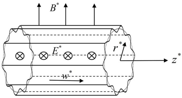
The EMHD flow inside a micropipe with stationary random surface roughness is shown in Figure 1. The cylindrical coordinate system (r*, θ, z*) is established, and the mean radius is R. The pipe is exposed to orthogonal magnetic and electric fields. The magnetic induction intensity B* of the constant magnetic field is oriented vertically upward with the magnitude B0, and the direction of the electric field strength E* with the magnitude E0 is from the outside to the inside. The combined effect of the electric and magnetic fields produces the Lorentz force J* × B* in the z-axis. The current density is J* = σ(E* + u* × B*), where σ stands for conductivity, and the velocity in cylindrical coordinate system is given as u*(u*,v*,w*). It is assumed that the fluid flow is along the z-direction; i.e., u* = 0, v* = 0, and w*(r*,θ) ≠ 0, and the velocity w* in the z-direction is the function of r* and θ for steady flow. For a small magnetic Reynolds number, the momentum equation and induced magnetic field equation can be decoupled, and the Navier–Stokes equation of MHD flow in the micropipe can be expressed as
| (1) |
where μ is the dynamic viscosity, is the pressure gradient, [28] is the modified pressure by magnetic pressure, and μm is the magnetic permeability. The rough wall of the micropipe can be written as , where n(θ) is a random process, and is a perturbation parameter. The no-slip boundary condition at can be expressed as
| (2) |
Figure 1.
Sketch of the EMHD flow inside a micropipe with stationary random surface roughness.
Assuming that n(θ) is a stationary random process and its mean is zero:
| (3) |
and the spectral representation of n(θ) by Fourier–Stieltjes integrals is:
| (4) |
where ω is the frequency domain parameter, and h(ω) is the spectral process of the n(θ). The spectral process increment dh(ω) has the following properties:
| (5) |
| (6) |
where the ˉ represents the complex conjugate, and F(ω) is a function defined by the correlation function of n(θ).
| (7) |
The correlation function of n(θ) can be expressed as a Fourier integral:
| (8) |
f(ω) is the spectral density of n(θ), expressed as
| (9) |
Then, the relation (6) becomes
| (10) |
Assuming that the scale of velocity is known to be U, utilizing R and μU/2R2 as the length and pressure scales, respectively, the nondimensional governing equations of (1) and (2) become
| (11) |
| (12) |
where , , and are the dimensionless electric parameter, the Hartmann number, and the dimensionless pressure gradient, respectively. Using the small parameter expansion method, the solution can be assumed as the form
| (13) |
By substituting (13) into (11), the governing equations for powers of ε are as follows:
| (14) |
| (15) |
| (16) |
By substituting (13) into the boundary conditions (12) and employing the Taylor expansion for the average position of the pipe walls (r = 1), we obtain the boundary condition as
| (17) |
On collecting terms of equal powers of ε, we obtain the boundary conditions for Equations (14)–(16), respectively:
| (18) |
| (19) |
| (20) |
From Equations (14) and (18), the leading-order solution can be solved as
| (21) |
where Ik represents the first kind of modified Bessel function of the order k.
Substituting the leading-order solution into condition (19), the second-order boundary condition can be expressed as
| (22) |
The first order solution w1(r,θ) is considered as a spectral representation, which is suggested by the condition (22)
| (23) |
The ordinary differential equation with respect to φ1 is obtained by substituting the solution (23) into the first-order Equation (15):
| (24) |
The general solution of Equation (24) is
| (25) |
where A and B are arbitrary constants. The boundary condition of Equation (24) is
| (26) |
Since φ1(0,ω) has a finite value, and Kω(0) trends to infinite, B is equal to 0. From condition (26) and general solution (25), Equation (24) can be solved as
| (27) |
Substituting expression (27) into (23), the analytic expression of w1(r,θ) becomes
| (28) |
Taking the leading-order and first-order solutions into condition (20), the second-order boundary condition is written as
| (29) |
where D(ω) is
| (30) |
The second order solution w2(r,θ) is considered as a spectral representation, which is suggested by the condition (29):
| (31) |
The ordinary differential equation satisfied by φ2(r) can be obtained by substituting Equation (31) into Equation (16):
| (32) |
The general solution of Equation (32) is
| (33) |
where A and B are arbitrary constants. The boundary condition of Equation (30) is
| (34) |
Similarly, since φ2(0,ω) has a finite value, B is equal to 0. From condition (34) and general solution (33), the solution of Equation (32) can be written as
| (35) |
Substituting expression (35) into (31), the analytic expression of w2(r,θ) becomes
| (36) |
The rate of flow per unit length in the micropipe is obtained as
| (37) |
The formula (37) can be expanded in the Taylor series about the mean wall positions r = 1:
| (38) |
Taking the average of formula (38), we obtain the expression as
| (39) |
The portions of the second-order term of ε taking the mean value are shown, respectively,
| (40) |
| (41) |
| (42) |
The mean rate of flow Q0 in a smooth micropipe is described as
| (43) |
Formula (39) can be arranged in the form of
| (44) |
where is defined as a deviation in the flow rate ratio with roughness to the case having no roughness in a smooth micropipe and
| (45) |
Assuming n(θ) holds Dirichlet’s condition, it can be expressed as a Fourier sinusoidal series:
| (46) |
where bk is the amplitude, and λ is the wave number. The correlation function and spectral density function of n(θ), respectively, are [22,23,24]
| (47) |
| (48) |
where δ(·) is the generalized Dirac function.
3. Two Special Examples
3.1. Sinusoidal Corrugation
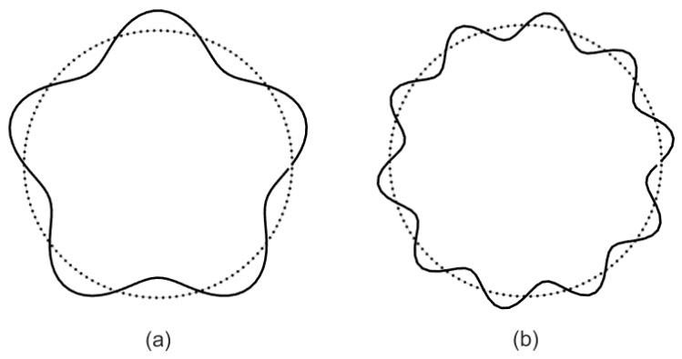
Using the results of the prior investigation, we consider two types of corrugations. The stationary random process n(θ) reduces to sin(λθ) when the micropipe has sinusoidal corrugation. According to (46), we can obtain that b1 = 1 and bk = 0, k ≥ 2 for n(θ) = sin(λθ) (Figure 2). Formula (44) in this situation can be written as
| (49) |
| (50) |
Figure 2.
Cross section of a cylindrical pipe with sinusoidal roughness. (a) ε = 0.15, λ = 5, (b) ε = 0.1, λ = 10.
3.2. Triangular Corrugation
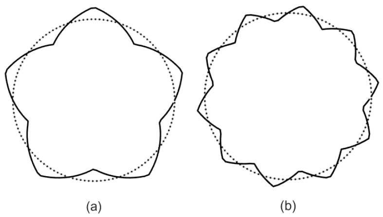
When the micropipe has triangular corrugation (Figure 3), the stationary random process n(θ) reduces to
| (51) |
Figure 3.
Cross section of a cylindrical pipe with triangular roughness. (a) ε = 0.15, λ = 5, (b) ε = 0.1, λ = 10.
Expanding (51) into a sinusoidal series, the radius of the micropipe with triangular corrugation is obtained:
| (52) |
where bn = 8(−1)n− 1/(π2(2n − 1)2). Formula (44) in this situation can be written as
| (53) |
| (54) |
4. Results and Discussion
Based on the reference [29], the range of dimensionless parameters is estimated as follows. The radius of the pipe is R~10–500 μm, viscosity μ~10−3–1.5 × 10⁻³ kg/(ms), electrical conductivity σ~2.2 × 10⁻⁴ S/m, and the strength of magnetic field B~0.01–1 T. The order of the Hartmann number O(Ha) ranges from 0 to 5, and the order of S ranges from 0 to 6 × 10³.
The influence of Ha on ζ1 is shown in Figure 4a, when the wave number λ = 0, 1, 3, 5, 10, and 15. A larger wave number means a rougher wall. ζ1 represents the deviation between the flow rate of a rough wall with sinusoidal corrugation and the flow rate of a smooth wall. ζ1 is positive, and it approaches 0 with the increase in Ha when the wave number is 3, 5, 10, and 15, which indicates that roughness has an impeding effect on flow, and the effect is gradually weakened with the increase in Ha. This phenomenon also occurs in the electromagnetic flow between microparallel plates with transversely wavy surfaces [22] and electromagnetic flow in microchannels with random surface roughness [27]. In particular, when the wave number is 0 and 1, the deviation is negative, and it approaches 0 with the increase in Ha, which means that roughness has a promoting effect on the flow, and the effect also weakens with the increase in Ha.
Figure 4.
The variations in the sinusoidal corrugation function ζ1 with (a) Ha for different λ, (b) λ for different Ha.
The influence of λ on ζ1 is shown in Figure 4b when the Hartmann number Ha = 0.1, 0.5, 1, 1.5, 3, and 5. The deviation ζ1 progressively increases from zero with the increase in wave number when the wave number is greater than 2. Since the deviation ζ1 is positive, it is clear that roughness impedes the flow on micropipe, and this effect steadily reinforces as the wave number grows. This conclusion is consistent with the conclusion in reference [22,27]. The deviation ζ1 approaches to 0 from a negative value with an increase in λ from 0 to 2, which also means that the roughness has a promoting effect on the flow, and the effect weakens with an increase in the wave number. A similar phenomenon also appears in Ref. [26], perhaps because the method has certain errors in the case of a small wave number.
The influence of Ha on ζ2 is shown in Figure 5a when the wave number λ = 0, 1, 3, 5, 10, and 15. ζ2 represents the deviation between the flow rate of a rough wall with triangular corrugation and the flow rate of a smooth wall. The influence of λ on ζ2 is shown in Figure 5b when Ha = 0.1, 0.5, 1, 1.5, 3, and 5. There are a few differences between Figure 4 and Figure 5. Figure 6 compares the two cases in detail.
Figure 5.
The variations in the triangular corrugation function ζ2 with (a) Ha for different λ, (b) λ for different Ha.
Figure 6.
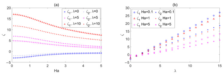
(a) depicts the change curves of ζ1 and ζ2 in relation to Ha when λ = 0, 5, and 10; (b) depicts the change curves of ζ1 and ζ2 in relation to λ when Ha = 0.1, 1, and 5.
The influence of Ha on deviation ζ1 and ζ2 with Ha when λ = 0, 5, and 10 is depicted in Figure 6a. Figure 6b depicts the influence of λ on deviation ζ1 and ζ2 when Ha = 0.1, 1, and 5. The graph indicates that ζ1 is greater than ζ2 for the same Ha and λ. This means that compared with triangular corrugation, sinusoidal corrugation has a larger resistant effect on flow. This conclusion is similar to the conclusion in Ref. [26].
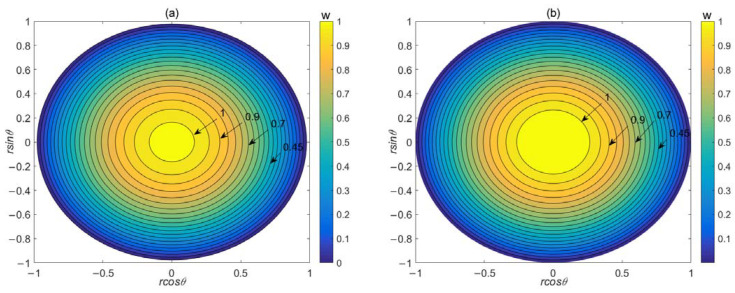
Figure 7 depicts the mean velocity distribution in the micropipe with both sinusoidal corrugation and triangular corrugation when P = −0.5, S = 8, Ha = 0.5, λ = 5, and ε = 0.1. Taking the average of velocity is essentially equivalent to taking the average of the surface roughness. This method is essentially used to transform the flow problem within micropipes with roughness into the problem within smooth micropipes. Because different roughness types have different effects on the flow inside the micropipes, this leads to different velocity distributions. The velocity distribution we obtained is actually the corrected velocity distributions of different types of roughness within smooth micropipes. From Figure 7a,b, it can be observed that at the same dimensionless parameters, the velocity distribution within micropipes with triangular corrugation is generally larger than that within micropipes with sinusoidal corrugation. The reason for this is that sinusoidal corrugation has a stronger influence on the flow rate compared with triangular corrugation. Under the same corrugation parameters, sinusoidal corrugation has a larger resistant effect on flow, resulting in lower flow velocities. This more intuitively demonstrates our conclusion about the influence of these two types of corrugated surfaces on flow rate.
Figure 7.
Mean velocity distribution in the micropipe with (a) sinusoidal corrugation and (b) triangular corrugation. P = −0.5, S = 8, Ha = 0.5, λ = 5, ε = 0.1.
5. Conclusions
The effect of random roughness on the electromagnetic flow in a micropipe is investigated using random function theory. The random corrugation function ζ, which is a measure of the flow rate deviation from the situation with no pipeline roughness, is analytically expressed by expanding the velocity with small parameters and using some stationary random process features. Two particular micropipes with sinusoidal and triangular corrugations are explored in this work. By examining graphical fluctuations in the roughness function concerning the Hartmann number Ha and wave number λ, it is revealed that the effect of roughness on the flow rate decreases with an increase in Ha and increases with an increase in the wave number λ. The sinusoidal corrugation has a stronger influence on the flow rate under the same values of Ha and λ compared with triangular corrugation. The mean velocity distribution indicates that the overall velocity within the micropipe with sinusoidal corrugation is relatively low. This is primarily due to the larger impact of sinusoidal corrugation on the flow rate. Meanwhile, this implies that the influence in obstructing the flow is more pronounced. This method is essentially used to transform the flow problem within micropipes with roughness into the problem within smooth micropipes to study the influence of roughness on the flow rate, and the velocity distribution will be different according to the different roughness types. This method is not only effective for a given corrugation but also effective for random roughness.
Abbreviations
The bold font represents vectors and the normal font represents scalars.
| (r,θ,x) | cylindrical coordinate system |
| B | magnetic field |
| B0 | the magnitude of the magnetic field |
| E | electric field |
| E0 | the magnitude of the electric field |
| J | electrical current density |
| u | velocity vector |
| σ | specific conductance |
| u, v, w | components of velocity vector |
| p | pressure of the liquid |
| R | channel radius |
| μ | dynamic viscosity |
| n(θ ) | stationary random functions |
| ε | amplitude of the corrugation |
| dh(ω) | interval random function |
| F(ω) | real non-decreasing bounded functions |
| f(ω) | spectral densities of n(θ) |
| C | correlation function |
| In | modified Bessel function of the first kind |
| Kn | modified Bessel function of the second kind |
| Ha | Hartmann number |
| S | dimensionless electric field strength |
| Q | flow rate per unit length |
| Q0 | the mean rate of flow in smooth micropipe |
| ζ | corrugation function |
| λ | wave number |
| δ | the Dirac generalized function |
| θ | phase difference |
Author Contributions
Z.W.: Investigation, Methodology, Validation, Formal analysis, Writing—original draft, Writing—review and editing. Y.S.: Visualization, Investigation, Methodology. Y.J.: Supervision, Writing—review and editing. All authors have read and agreed to the published version of the manuscript.
Data Availability Statement
Data sharing not applicable.
Conflicts of Interest
The authors declare no conflict of interest.
Funding Statement
The authors acknowledge the financial support provided by the National Natural Science Foundation of China (Grant No. 12262026), the Natural Science Foundation of Inner Mongolia Autonomous Region of China (Grant No. 2021MS01007), the Program for Innovative Research Team in Universities of Inner Mongolia Autonomous Region (Grant No. NMGIRT2323), the Inner Mongolia Grassland Talent (No. 12000-12102013), and the Research Program of Science and Technology at Universities of Inner Mongolia Autonomous Region (Grant No. NJZY23054).
Footnotes
Disclaimer/Publisher’s Note: The statements, opinions and data contained in all publications are solely those of the individual author(s) and contributor(s) and not of MDPI and/or the editor(s). MDPI and/or the editor(s) disclaim responsibility for any injury to people or property resulting from any ideas, methods, instructions or products referred to in the content.
References
- 1.Laser D.J., Santiago J.G. A review of micropumps. J. Micromech. Microeng. 2004;14:R35–R64. doi: 10.1088/0960-1317/14/6/R01. [DOI] [Google Scholar]
- 2.Shojaeian M., Shojaeian M. Analytical solution of mixed electromagnetic/pressure driven gaseous flows in microchannels. Microfluid. Nanofluid. 2012;12:553–564. doi: 10.1007/s10404-011-0897-z. [DOI] [Google Scholar]
- 3.Xie Z.Y., Jian Y.J. Rotating electroosmotic flow of power-law fluids at high zeta potentials. Colloid Surf. A. 2014;467:231–239. doi: 10.1016/j.colsurfa.2014.07.051. [DOI] [Google Scholar]
- 4.Jian Y.J., Liu Q.S., Yang L.G. AC electroosmotic flow of generalized Maxwell fluids in a rectangular microchannel. J. Non-Newton. Fluid Mech. 2011;166:1304–1314. doi: 10.1016/j.jnnfm.2011.08.009. [DOI] [Google Scholar]
- 5.Jian Y.J., Su J., Chang L., Liu Q.S., He G.W. Transient electroosmotic flow of general Maxwell fluids through a slit microchannel. Z. Angew. Math. Phys. 2014;65:435–447. doi: 10.1007/s00033-013-0341-1. [DOI] [Google Scholar]
- 6.Jian Y.J., Yang L.G., Liu Q.S. Time periodic electro-osmotic flow through a microannulus. Phys. Fluids. 2010;22:042001. doi: 10.1063/1.3358473. [DOI] [Google Scholar]
- 7.Li S.X., Jian Y.J., Xie Z.Y., Liu Q.S., Li F.Q. Rotating electro-osmotic flow of third grade fluids between two microparallel plates. Colloid Surf. A. 2015;470:240–247. doi: 10.1016/j.colsurfa.2015.01.081. [DOI] [Google Scholar]
- 8.Qin M., Bau H.H. When MHD-based microfluidics is equivalent to pressure-driven flow. Microfluid. Nanofluid. 2011;10:287–300. doi: 10.1007/s10404-010-0668-2. [DOI] [Google Scholar]
- 9.Ezzat M.A. Thermoelectric MHD non-Newtonian fluid with fractional derivative heat transfer. Physica B. 2010;405:4188–4194. doi: 10.1016/j.physb.2010.07.009. [DOI] [Google Scholar]
- 10.Jang J., Lee S.S. Theoretical and experimental study of MHD magnetohydrodynamic micropump. Sens. Actuators A-Phys. 2000;80:84–89. doi: 10.1016/S0924-4247(99)00302-7. [DOI] [Google Scholar]
- 11.Ho J.E. Characteristic study of MHD pump with channel in rectangular ducts. J. Mar. Sci. Tech. 2007;15:315–321. doi: 10.51400/2709-6998.2048. [DOI] [Google Scholar]
- 12.Moghaddam S. Analytical solution of MHD micropump with circular channel. Int. J. Appl. Electrom. 2012;40:309–322. doi: 10.3233/JAE-2012-1594. [DOI] [Google Scholar]
- 13.Homsy A., Koster S., Eijkel J.C.T., Berg A., Lucklum F., Verpoorte, DeRooij N.F. A high current density DC magnetohydrodynamic (MHD) micropump. Lab Chip. 2005;5:466–471. doi: 10.1039/b417892k. [DOI] [PubMed] [Google Scholar]
- 14.Gao C.H., Jian Y.J. Analytical solution of magnetohydrodynamic flow of Jeffrey fluid through a circular microchannel. J. Mol. Liq. 2015;211:803–811. doi: 10.1016/j.molliq.2015.08.004. [DOI] [Google Scholar]
- 15.Cheng C.-K., Cho C.-C. Electrokinetically-driven flow mixing in microchannels with wavy surface. J. Colloid Interface Sci. 2007;312:470–480. doi: 10.1016/j.jcis.2007.03.033. [DOI] [PubMed] [Google Scholar]
- 16.Nishimura T., Bian Y.N., Kunitsugu K. Mass-Transfer Enhancement in a Wavy-Walled Tube by Imposed Fluid Oscillation. AIChE J. 2004;50:762–770. doi: 10.1002/aic.10070. [DOI] [Google Scholar]
- 17.Ligrani P., Blanchard D., Gale B. Slip due to surface roughness for a Newtonian liquid in a viscous microscale disk pump. Phys. Fluids. 2010;22:052002. doi: 10.1063/1.3419081. [DOI] [Google Scholar]
- 18.Phan-Thien N. On the stokes flow of viscous fluids through corrugated pipes. J. Appl. Mech. 1980;47:961. doi: 10.1115/1.3153825. [DOI] [Google Scholar]
- 19.Kwang-Hua Chu Z. Slip flow in an annulus with corrugated walls. J. Phys. D Appl. Phys. 2000;33:627. doi: 10.1088/0022-3727/33/6/307. [DOI] [Google Scholar]
- 20.Grant Mills Z., Shah T., Warey A., Balestrino S., Alexeev A. Onset of unsteady flow in wavy walled channels at low reynolds number. Phys. Fluids. 2014;26:084104. doi: 10.1063/1.4892345. [DOI] [Google Scholar]
- 21.Buren M., Jian Y.J., Chang L. Electromagnetohydrodynamic flow through a microparallel channel with corrugated walls. J. Phys. D Appl. Phys. 2014;47:425501. doi: 10.1088/0022-3727/47/42/425501. [DOI] [Google Scholar]
- 22.Buren M., Jian Y.J. Electromagnetohydrodynamic (EMHD) flow between two transversely wavy microparallel plates. Electrophoresis. 2015;36:1539–1548. doi: 10.1002/elps.201500029. [DOI] [PubMed] [Google Scholar]
- 23.Phan-Thien N. On Stokes flow between parallel plates with stationary random surface roughness. Z. Angew. Math. Mech. 1980;60:675–679. doi: 10.1002/zamm.19800601206. [DOI] [Google Scholar]
- 24.Wang C.Y. On Stokes flow between corrugated Plates. J. Appl. Mech. 1979;46:462–464. doi: 10.1115/1.3424575. [DOI] [Google Scholar]
- 25.Phan-Thien N. On Stokes flows in channels and pipes with parallel stationary random surface roughness. Z. Angew. Math. Mech. 1981;61:193–199. doi: 10.1002/zamm.19810610308. [DOI] [Google Scholar]
- 26.Faltas M.S., Sherief H.H., Mansour M.A. Slip-brinkman flow through corrugated channel with stationary random model. J. Porous Media. 2017;20:723–748. doi: 10.1615/JPorMedia.v20.i8.40. [DOI] [Google Scholar]
- 27.Ma N.L., Sun Y.J., Jian Y.J. Electromagnetohydrodynamic (EMHD) Flow in a Microchannel with Random Surface Roughness. Micromachines. 2023;14:1617. doi: 10.3390/mi14081617. [DOI] [PMC free article] [PubMed] [Google Scholar]
- 28.Chandrasekhar S. Hydrodynamic and Hydrodynamic Stability. Oxford University Press; London, UK: 1961. [Google Scholar]
- 29.Jian Y.J. Transient MHD heat transfer and entropy generation in a microparallel channel combined with pressure and electroosmotic effects. Int. J. Heat Mass Transf. 2013;89:193–205. doi: 10.1016/j.ijheatmasstransfer.2015.05.045. [DOI] [Google Scholar]
Associated Data
This section collects any data citations, data availability statements, or supplementary materials included in this article.
Data Availability Statement
Data sharing not applicable.


