

Abstract
This paper reports on the development of a novel soft robotic system for remote ultrasound applications. Direct contact of the ultrasound probe with the patient's body represents a safety risk and therefore control of the probe's positioning and applied force is a crucial task. The proposed robot uses a passive control system that provides safe interaction between the robot and the patient by leveraging soft robotics technology. The soft robot's structure can be considered as a nonlinear spring which can be designed to exert a safe force within the robot's workspace to guarantee the safety of human–robot interaction. The literature suggests that effective ultrasound imaging of both the heart and abdomen requires six degrees-of-freedom. These degrees-of-freedom consist of three translational motions, which are achieved using a novel hybrid soft cable-driven parallel robot, and three wrist motions, which is based on a universal joint design. The experimental results show that the robot can achieve all these six degrees-of-freedom, and its blocking force can be engineered to generate a uniform force within the workspace.
1 Introduction
Ultrasound imaging is one of the least invasive and most cost-effective imagining modalities, which is widely used in diagnostic applications. However, this modality is notoriously difficult to interpret due to a relatively small field of view and contrast features. Therefore, specialists are typically required to both control and interpret the acquired images. This requirement has led to the development of robotic systems as an alternative to human control, particularly in remote applications (e.g., natural disasters and low-income settings) that require portable systems.
Application of soft robotics technology for biomedical applications encourages safe human interactions which are less invasive, and cost-effective [1–4]. This paper aims to develop a remote ultrasound robotic system. Application of soft material provides easy access for ultrasound imaging procedures at odd angles, less human intervention, and human error. Portable ultrasound systems are capable of imaging procedures during natural disasters and low-income families. Ren et al. developed a portable and wearable soft robotic system that achieves movements in three different directions to successfully proceed through ultrasound imaging automatically. The soft robot replaces mechanical robots with its mechanical movement, allowing the soft robot to move with 3 degrees-of-freedom by pressurized air actuated by the soft robot [5]. The system encourages the replacement of manual workloads, which then leads to the minimization of demanding clinical tasks.
Soft material provides safe interaction between robot and human biomedical applications [6,7]. Lindenroth et al. advanced in a parallel soft robot that uses soft fluidic actuators to establish safe adaptable interaction between ultrasound probe and patient with force levels that are required to process good quality ultrasound images and demonstrate controllability and imaging capabilities on the patient. The soft robot provides a stable and consistent contact between the probe and patient, which improves the strain injury sonographers experience [8]. Rigid robotic systems rely on active force control methods for safe human robot interaction and biomedical environment [9]; however, soft robotic systems take advantage of passive force control mechanisms.
In the biomedical engineering field, Yang et al. experienced more exploration in nanomaterials and nanosoft robots in applications that include basic invasive surgery in the human body beneath skin and surgery to physical rehabilitation [10]. Due to compliance and soft material properties of the material, soft robots are adequate for the accurate and meticulous requirements produced by biomedical field applications. A soft robotic cable-driven manipulator that utilizes magnetic resonance imaging (MRI) to image soft tissue contrast to detect brain tumors and abnormalities. Kim et al. advanced in a soft robot is used to remove brain tumors, which reduces hand tremor and increases accuracy, in the future improves neurosurgery [11].
The body of the soft robot consists of springs for continuous actuation and flexibility. A seven degree-of-freedom cable-driven arm with a shoulder, elbow, and a wrist; it allows for high flexibility. Cui et al. developed the exoskeleton (CAREX-7), which is used for dexterous motion such as assistance, training, or rehabilitation of a whole-arm [12,13]. Cable-driven robots transmit motion and forces by the cables, to allow the actuators to be attached away from the links [14], the CAREX-7 uses the lightweight cables to actuate the cuffs that are attached to the human limbs, granting low weight, inertia, and cost. Usually, 6 degrees-of-freedom are implemented, but the more degrees-of-freedom a robot has the more points of weakness; once a link fails the entire robot begins to malfunction.
The paper is organized as follows. In Sec. 2, the design and fabrication process of the remote ultrasound system will be discussed. Section 3 contains controls and modeling used to actuate the system as accurately as well as model the system correctly to estimate system configurations. Section 4 provides the experimental data and results of the robot. Finally, Sec. 5 is the conclusion.
2 Design
This section discusses the design and fabrication of the remote ultrasound soft robot and demonstrates the experimental results. In the first part, the concept of hybrid soft cable-driven parallel robots will be discussed. Next, the designed objective for the soft ultrasound robot will be detailed, and finally, the design and fabrication of the soft robot prototype will be presented. In our previous research works [15–19] we have detailed the design, and fabrication of two, three, and six degrees-of-freedom (DOFs) soft robots.
According to Fig. 1, soft parallel robots can be designed by replacing the rigid links and joints in the structure of rigid parallel robots with soft links and joints [18]. The addition of soft links to the structure of soft parallel robots will provide an extra design feature to adjust the overall stiffness of the robot. Thus, by engineering the stiffness of the robot we can guarantee safe human robot interaction. In the design of soft parallel robots typically soft active links transfer the desired motion to the robot end-effector.
Fig. 1.

Evolution of design from a rigid parallel robot to a hybrid cable-driven soft parallel robot
Considering the nonlinear complex deformation of soft links, modeling and control of soft parallel robots can be challenging. Alternatively, we can directly transfer the motion to the end-effector using cable-driven actuators combined with passive soft links (Figs. 1(c) and 1(d)). This new design, which combines cable-driven robots and soft robots has the potential to simplify the modeling and control of the soft robots (Fig. 1(d)).
2.1 Designed Objective for the Soft Ultrasound Robot.
The soft robot must have 6DOF (three translations and three rotations), its workspace must cover an area of interest above the abdomen of the patient, and overall stiffness of the soft robot must be designed such that it can apply the required forces for proper imaging and be within the safe range for the patient. Figure 2 illustrates the basic design strategy for the soft ultrasound robot. The structure of the soft robot can be considered as a nonlinear spring where the reaction force of the soft robot (F) is the function of robot displacement (g(Δx)).
Fig. 2.

Mechanical design of the soft robot structure: (a) The soft robot can be considered as nonlinear spring which requires to have proper longitudinal and shear stiffness. (b) An analogous linear spring example can be used to explain the design process: once the required range of motion is obtained from the kinematic model, the stiffness of the spring can be optimized to satisfy the constrain on the required blocking force of the system.
The complete design process will require several iterations to optimize the shape and number of the soft links for a given set of workspace and force constraints according to Fig. 2(b). In this case, can start the design process based on the workspace constraint (this is the required area to be scanned on the patient body) to obtain the length of the soft links and size of the based and moving platform of the robot and consequently change the thickness and number of soft links to satisfy the force constraint (this is the required force for ultrasound imaging).
This process can be repeated several times so that it can converge to an optimal solution. While obtaining an optimal solution is beyond the scope of the current work, we will demonstrate that the robot can achieve six DOF, and its interaction force is relatively uniform within its workspace and can be adjusted by changing the number of soft links used in the design.
2.2 Soft Cable-Driven Parallel Robot.
To create a parallel robot with six DOF the starting design point can be the structure of well-known Stewart mechanism [20]. This mechanism consists of a fixed and a moving platform which are connected together through six linear actuators. To transform this mechanism to its equivalent hybrid soft cable-driven parallel robot, the six linear actuators can be replaced by six cable-driven actuators which connect the fixed plat form to the moving plat form through soft links. Our initial experimental data demonstrated that while the Stewart mechanism design can effectively create three translational motions for the soft robot, it fails to generate the required orientation for the robot. Thus, we decided to modify the design and use only three cable driven actuators to create the required three translational motions and adding a three DOF wrist to moving plat form to accommodate the required orientation of the robot, this is displayed in Fig. 3 below.
Fig. 3.

(a) Computer-aided design (CAD) model and three-dimensional (3D) printed prototype of the soft robot with three-soft links. (b) CAD model and 3D printed prototype of the soft robot with six-soft links.
According to Fig. 3, the robot consists of a fixed and a moving platform which are connected with three or more passive soft links (we have shown three and six links designs, however, to satisfy the force constraint more soft links can be added as needed). Three electromotors 120 deg apart actuate the moving platform through cable and pulley mechanism. This will create three translational motions, and to generate three rotations a three DOF wrist mechanism is added to the top platform.
The base is circular with three mounting plates around the outer diameter of the base. Each of the servos are placed at an angle of about 15 deg from each of the two edge anchor points of the top platform and shifted about 4 cm clockwise around the base, to avoid slippage and provide accurate tension from the cables. The servos control the winded cable around the wire wheel and secure at the anchor points of the top platform. The top platform is also rigid to support uniformity of forces applied from the top section. The top section holds the 9 g servo that actuates the universal joint. The cables keep the links in tension and provide flexibility in complex environments for motion. The links are connected to the top and bottom base to grant constant force when applied and nonlinear actuation.
2.3 Three Degrees-of-Freedom Wrist (Universal Joint Design).
Probably the simplest design to create a three DOF wrist is to use a three perpendicular axis rotation by adding a yaw motion to a universal joint. The universal joint is composed of 3 parts: two yokes and a cross. One yoke and two opposite rods of the cross contain a servomount to hold the servo-and produce desired motion. Two rods are secured together with a screw to assemble a cross. The universal joint pictured in Fig. 4 below, is controlled by three 9 gm servos, and the first servo is in the slot of the top platform to produce yaw movement. The two remaining servos are attached, one at each opposite yoke to produce roll and pitch movements. Figure 5 shows the CAD model of the soft ultrasound robot and how it will be mounted to perform the imaging procedure.
Fig. 4.

(a) CAD Assembly design of the universal joint. (b) 3D printed prototype of the universal joint.
Fig. 5.

Frame assignment for the soft parallel robot
2.4 Fabrication of the Soft Robot.
The printing parameters were optimized to acquire the best results and save material. The remote ultrasound robot uses common materials for 3D printers, such as polylactic acid and Ninjaflex for simple and low-cost fabrication [20,21]. The soft links, which are pliable and hexagonal shaped, were printed with Ninja with 80% infill. Meanwhile, the base, top platform, wire wheels, servoholders, servomounts and the components of the universal joint, were all produced using PLA and printed with 80% infill. The cross of the universal joint is printed separately into two rods for security and simple assembly. One end of each rod is printed with servomounts to produce the necessary movements, such as roll, pitch and yaw. The two yokes were printed in two parts in polylactic acid to secure the cross and the yokes.
3 Modeling and Control
This section discusses the kinematic modeling and the trajectory planning of the ultrasound robot, all code is executed in matlab or in the Arduino microcontroller. The kinematic model consists of two components. The first part is the model of the hybrid soft cable-driven robot which generates three translational motions in x, y, and z directions, and the second part of simulation uses the rotation matrix (Euler angels) to generate the orientation of the robot using the three DOF wrist.
3.1 Soft Cable Driven Controls.
To develop the kinematics model of the soft robot we assume that the cables are always in tension (this is due to the stiffness of soft passive links), and the moving platform remains parallel to the bottom platform. Next, proper frames will be assigned to the soft robot platforms. Based on Fig. 5, the kinematics model of the soft robot can be defined as follows:
| (1) |
where is the position of the vertex of robot fixed platform, is the position of the cables, is the position of the end-effector, and is the position of the vertex of moving platform.
3.2 Universal Joint Controls.
This section covers the controls used to derive the desired trajectory of the universal joint as well as the servo-inputs needed to complete these trajectories. The controls of the universal joint are straightforward, the user is able to input the movement that is desired in roll, pitch and yaw movements as well as how long the pattern should be actuated. The script then applies the movement pattern over the desired time-frame and finds the angle desired for each servo-over the trajectory. The script then stores all of these angles in an array that is used later in the controls process. It is worth noting that the time-frame used in this script is often imported from the hybrid soft cable driven controls to ensure that the system actuates for the same amount of time across each of the six servos as shown in Figs. 6–8.
Fig. 6.

Simulation of the kinematics model: (a) circular trajectory and (b) associated change in the cable length
Fig. 8.

Simulation of the kinematics model: (a) helical trajectory and (b) associated change in the cable length
Fig. 7.

Simulation of the kinematics model: (a) square trajectory and (b) associated change in the cable length
3.3 Communications and Coupled Controls.
This section details the Full controls flow as well as the communication process between the different scripts for generating the hybrid soft cable driven trajectory, the universal joint trajectory, and the Arduino microcontroller. The basic control flow is detailed in the Fig. 9 below.
Fig. 9.

Controls flow for ultrasound robotic system. The control system is divided into two parts. The left part comprises the matlab scripting steps, and the right is the Arduino scripting and controls steps.
The controls flow described in Fig. 9 is separated into two parts, matlab and arduino. The matlab controls flow goes as follows. The desired X, Y, Z, roll, pitch, yaw trajectories are input by the user into their respective scripts. From there, the desired trajectory for the X, Y, and Z movement is given to the model of the hybrid soft robot system which outputs the changes in the lengths of the cables needed to complete the trajectory. The Universal joint trajectory planning uses the rotational matrix of the robot to calculate the angles for each servo on the universal joint for each given point.
These angles as well as the changes in length derived from the model of the hybrid soft cable driven system are given to the control merging and transformation script which finds the angles of the bottom three servomotors required to actuate to the desired position and combines these angles with the universal joint controls into a single control matrix. This matrix is then given to the Arduino communication script which transmits the angles to the Microcontroller. This begins the Arduino controls flow; the Arduino is receiving the angles via serial communication from the laptop. It reads in the six desired angles simultaneously for each point in the trajectory. Then the microcontroller sends each desired angle to the servos in both the universal join and to the servos in the base-plate of the hybrid soft cable driven system.
4 Experimental Results and Setup
In this section, the experimental setup and results are performed to demonstrate and to measure the relative error of different types of trajectories between the typical kinematics of a steward robot and this robot. The position data was taken for all six degrees-of-freedom in several different trajectories detailed below. The force data was collected on the ultrasound robotic system, that utilizes 3 support links and 6 support links. The data from all tests as well as a brief discussion of the strengths and weaknesses of the system are contained in Sec. 4.1.
4.1 Experimental Setups.
The experimental setups for the testing processes for both the position and force data are detailed in this section. The first setup, described in Fig. 10, was used to take all position setup as well as all roll, pitch and yaw data. This experimental setup consists of the ultrasound robot as well as an external power supply to support the six servos in the system. A laptop is used to connect to the Arduino microcontroller used in the ultrasound robot.
Fig. 10.

Experimental setup for X, Y, Z and Roll, Pitch, and Yaw data. The power supply, electromagnetic transmitter, ultrasound robot, position sensor, sensor electronics unit, and laptop are all labeled.
This laptop runs the matlab scripts used to create the desired trajectories and send the desired angles to the ultrasound robot. The sensor electronics unit connects to the electromagnetic transmitter and the position sensor, which reads in its position compared to the transmitter. The position sensor is affixed to the top of the universal joint of the robot then the position data is taken from the different trajectories tested.
The next experimental setup, displayed in Fig. 11 was used in the force profile testing that was done on the system. This experimental setup also contains the ultrasound robot system as well as an external power supply for the actuation of the servos in the system. The laptop is attached to the Arduino microcontroller to control the system's actuation during force testing. The force sensor in the setup is attached to the laptop to be able to send live force data from the system to the laptop where it is then processed.
Fig. 11.

Experimental setup for force data. The power supply, ultrasound robot, force sensor, and laptop are all labeled.
Now that the experimental setups have been defined the remaining sections will cover the data recorded over the testing process.
4.2 Roll, Pitch, Yaw Data.
This section details the data taken from the universal joint attached to the robotic system. The data recorded was applied to three different rotational movements in a 3D space. The universal joint accomplished movements in 3D to present increased flexibility in all directions. The movements recorded by the universal joint are as follows roll, pitch and yaw. The experiment was established to ensure stability, maneuverability, and efficiency. Position data were recorded and determined in matlab.
For all movements, there is an experimental movement of the universal joint on the ultrasound robot and a desired path of the universal joint. Beside the position data there is the recorded error along the roll, pitch and yaw axis. Figure 12 below illustrates the experimental trajectory and planned trajectory of roll.
Fig. 12.

Roll, pitch, yaw data in degrees. The sine wave control used for each of the trajectories is in blue and the experimental data are in a red dotted line.
Figure 12 exhibits the experimented position data of the roll, pitch and yaw movement in degrees. The generated movement is shown in blue while the experimental trajectory is shown in red dashes. The experimental data shows a clear depiction of the planned path, although there are some errors in the recorded data. There is minuscule error within the roll, pitch and yaw collected data displays a distinct pattern within all the position data. Throughout the collected roll, pitch and yaw trajectories the graph depicts that the data has less curvature than the planned trajectory.
4.3 Movement Data.
This section is comprised of the experimental setup that measures position data. The results were performed on several different trajectories. The ultrasound robot can perform complex movements, which provides increased functionality and improved accuracy. The trajectories recorded within the experiment are circle, square and spiral trajectories. For each of the following trajectories, the experimental data is projected along with the planned trajectory. Alongside the trajectories is the error aligned the X, Y, Z axis. Position data analysis and graphing was concluded in matlab. The graph below is experiment trajectory and desired trajectory of a square.
Figure 13 shows the results of the square trajectory. The planned square trajectory is demonstrated in blue while the experimental square trajectory from ultrasound robotic system is shown in red dashes. The experimental results show a change in the recorded position data, where there are changes in the X and Y axis. The experimental trajectory accomplished by the ultrasound robot displays a clear representation of the planned trajectory, though there are errors within the resulting data. In the X direction, there was error present at the peak of around 9 mm, and in the Y direction there was error, peaking at 5 mm.
Fig. 13.

(a) Square trajectory versus desired trajectory. The planned trajectory is in blue and the red dotted line is the data recorded by the first experimental setup. (b) Y and X error of the square trajectory the top subgraph is Y error and the bottom subgraph is X error.
Figure 14 above is the resulting data of the circle trajectory. The experiment was conducted to examine the performance of the ultrasound robot in achieving smooth motion, in both X and Y directions. The planned circle trajectory is demonstrated in blue while the experimental circle trajectory is represented by red dashes. The path planned is a circle, but the results of the robot produced a slightly shifted circle trajectory. The maximum error in the X direction reached 7 mm, while the error in the Y direction maxed at 6 mm.
Fig. 14.

(a) Circle trajectory versus desired trajectory. The planned trajectory is in blue and the red dotted line is the data recorded by the first experimental setup. (b) Y and X error of the circle trajectory the top subgraph is Y error, and the bottom subgraph is Xerror.
Figure 15 above displays a spiral trajectory. The data collected were from a 3D experimental test, this test aims to evaluate ultrasound robot's accuracy in executing movements in all special directions. The desired spiral trajectory is demonstrated in blue, and the resulting circle trajectory is displayed in red dashes. The experimental data evidently represents the planned path of a spiral. The error demonstrated by the experimental trajectory was minuscule, in the Z direction there was a maximum error of 3 mm. In the X and Y direction the errors resulted in the ultrasound robot peaked at about 4 mm, though the error is slightly more error in X and Y direction than in the Z direction.
Fig. 15.

(a) Spiral trajectory versus desired trajectory. The planned trajectory is in blue and the red dotted line is the data recorded by the first experimental setup. (b) Y, X, and Z error of the spiral trajectory the top subgraph is the Z error the middle subgraph is the Y error and the bottom subgraph is X error.
4.4 Force Profile.
This section explains the basic force profile that was collected from the soft robotic system. The profile was created using the second experimental setup detailed in Sec. 4.3. The force profile was taken for two different versions of the soft robotic system one with three soft supports and six soft supports, and these two models are displayed in Fig. 16.
Fig. 16.
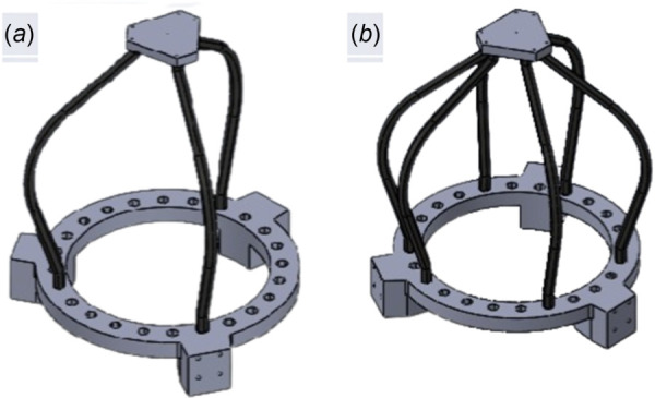
(a) CAD Assembly of the three-support system and (b)CAD assembly of the six-support system
The data were taken using various circle trajectories, a circle with radii of 0.05 m, 0.025 m, and 0.01 m, the data were also taken at the normal operating height at both systems. The data were taken by having the robot actuate in said circles stopping ten times in every circle, the robot then realizes a bit of tension from the cables causing the top part of the system to drift up slightly. The force sensor is placed on the top as it drifts upward and the force at that point is then recorded digitally using measurelite software. The trajectory stopping points are listed in Fig. 17.
Fig. 17.

It shows stopping points and workspace for force testing. The blue triangle displays the fixed based of the robot, and the lines between stopping points are used to categorize the data later.
The three circles of red points represent the stopping points where the force data was recorded. The points of the blue triangle represent the placement of each of the servos in the base-plate of the hybrid soft cable driven robot. The data was recorded starting at the rightmost point of the largest circle, clockwise around the largest circle, then inward to the smaller circle. The data from the testing is displayed in Tables 1 and 2.
Table 1.
Testing data from six support in Newtons. The data max is 6.69 N, and the minimum is 6.25 N.
| Angle (deg) | 5 mm | 2.5 mm | 1 mm | 1 mm | 2.5 mm | 5 mm |
|---|---|---|---|---|---|---|
| 0 | 6.66 | 6.47 | 6.25 | 6.36 | 6.47 | 6.61 |
| 36 | 6.5 | 6.55 | 6.74 | 6.58 | 6.57 | 6.49 |
| 72 | 6.45 | 6.51 | 6.5 | 6.5 | 6.57 | 6.51 |
| 108 | 6.64 | 6.62 | 6.54 | 6.45 | 6.69 | 6.57 |
| 144 | 6.61 | 6.52 | 6.61 | 6.48 | 6.61 | 6.57 |
Table 2.
Testing data from three support in Newtons. The data max is 2.89 N, and the minimum is 2.69 N.
| Angle (deg) | 5 mm | 2.5 mm | 1 mm | 1 mm | 2.5 mm | 5 mm |
|---|---|---|---|---|---|---|
| 0 | 2.73 | 2.76 | 2.74 | 2.74 | 2.91 | 2.79 |
| 36 | 2.82 | 2.78 | 2.76 | 2.81 | 2.75 | 2.81 |
| 72 | 2.75 | 2.81 | 2.82 | 2.76 | 2.73 | 2.72 |
| 108 | 2.85 | 2.92 | 2.69 | 2.77 | 2.89 | 2.81 |
| 144 | 2.85 | 2.84 | 2.86 | 2.84 | 2.64 | 2.64 |
The two tables cover force data from the six-support setup 1 and the second being from the three-support setup 2. The first ten testing data points represent the largest circle, data points eleven through twenty represent the middle circle and data points twenty-one through thirty represent the smallest circle. The data across all three circles for both the six- and three-support setups is quite consistent. The six-support setup produces a constant force of approximately 6.6 N at all data points tested. The three-support setup produces a constant force of approximately 2.7 N at all data points tested.
There were no large spikes of force in the data at any tested point, showing that the system's supportive force output is constant across the central workspace. The force could be alerted by doing this trajectory at a different Z point making it closer or farther from the base-plate. The number of soft supports could also be changed until the desired static supporting force is reached.
5 Conclusion
This paper discussed the development of a novel ultrasound robotic system. Through numerical simulations and experimental results, it has been shown that the robot has six DOF and can move in any 3D arbitrary trajectories within its workspace. The blocking force of the robot has been measured and showed that it is uniform in any radial direction within the workspace.
Moreover, by changing the number of passive links from three to six, it has been shown that the blocking force of the robot can be adjusted to satisfy the force constraint of the problem. Our future work includes the development of closed-loop control systems for robust position control of the robot, optimization of the robot soft links so that it can be used for abdomen ultrasound imaging, and integration of six DOF joystick to steer the robot remotely.
Acknowledgment
The research reported in this publication was partially supported by the National Institute of Biomedical Imaging and Bio-engineering of the National Institutes of Health under Award No. R15EB032189. The content is solely the responsibility of the authors and does not necessarily represent the official views of the National Institutes of Health. Turaj Ashuri, and Amir Ali Amiri Moghadam would like to thank Kennesaw State University for the support received. SA thank New Mexico State University for their support.
Data Availability Statement
The datasets generated and supporting the findings of this article are obtainable from the corresponding author upon reasonable request.
References
- [1]. Gong, Z. , Cheng, J. , Chen, X. , Sun, W. , Fang, X. , Hu, K. , Xie, Z. , Wang, T. , and Wen, L. , 2018, “ A Bio-Inspired Soft Robotic Arm: Kinematic Modeling and Hydrodynamic Experiments,” J. Bionic Eng., 15(2), pp. 204–219. 10.1007/s42235-018-0016-x [DOI] [Google Scholar]
- [2]. Goldfield, E. C. , Park, Y.-L. , Chen, B.-R. , Hsu, W.-H. , Young, D. , Wehner, M. , Kelty-Stephen, D. G. , et al., 2012, “ Bio-Inspired Design of Soft Robotic Assistive Devices: The Interface of Physics, Biology, and Behavior,” Ecological Psychol., 24(4), pp. 300–327. 10.1080/10407413.2012.726179 [DOI] [Google Scholar]
- [3]. Ashuri, T. , Armani, A. , Jalilzadeh Hamidi, R. , Reasnor, T. , Ahmadi, S. , and Iqbal, K. , 2020, “ Biomedical Soft Robots: Current Status and Perspective,” Biomed. Eng. Lett., 10(3), pp. 369–385. 10.1007/s13534-020-00157-6 [DOI] [PMC free article] [PubMed] [Google Scholar]
- [4]. Parsa, F. , Moghadam, A. A. A. , Stollberg, D. , Tekes, A. , Coates, C. , and Ashuri, T. , 2022, “ A Novel Soft Robotic Hand for Prosthetic Applications,” IEEE 19th International Conference on Smart Communities: Improving Quality of Life Using ICT, IoT and AI (HONET), Marietta, GA, Dec. 19–21, pp. 1–6. 10.1109/HONET56683.2022.10019175 [DOI] [Google Scholar]
- [5]. Ren, H. , Gu, X. , and Tan, K. L. , 2016, “ Human-Compliant Body-Attached Soft Robots Towards Automatic Cooperative Ultrasound Imaging,” IEEE 20th International Conference on Computer Supported Cooperative Work in Design (CSCWD), Nanchang, China, May 4–6, pp. 653–658. 10.1109/CSCWD.2016.7566066 [DOI] [Google Scholar]
- [6]. Cianchetti, M. , Laschi, C. , Menciassi, A. , and Dario, P. , 2018, “ Biomedical Applications of Soft Robotics,” Nat. Rev. Mater., 3(6), pp. 143–153. 10.1038/s41578-018-0022-y [DOI] [Google Scholar]
- [7]. Yang, Y. , Li, Y. , and Chen, Y. , 2018, “ Principles and Methods for Stiffness Modulation in Soft Robot Design and Development,” Bio-Des. Manuf., 1(1), pp. 14–25. 10.1007/s42242-018-0001-6 [DOI] [Google Scholar]
- [8]. Lindenroth, L. , Housden, R. J. , Wang, S. , Back, J. , Rhode, K. , and Liu, H. , 2020, “ Design and Integration of a Parallel, Soft Robotic End-Effector for Extracorporeal Ultrasound,” IEEE Trans. Biomed. Eng., 67(8), pp. 2215–2229. 10.1109/TBME.2019.2957609 [DOI] [PMC free article] [PubMed] [Google Scholar]
- [9]. Banerjee, H. , Tse, Z. T. H. , and Ren, H. , 2018, “ Soft Robotics With Compliance and Adaptation for Biomedical Applications and Forthcoming Challenges,” Int. J. Robot. Autom., 33(1), pp. 69–80. 10.2316/Journal.206.2018.1.206-4981 [DOI] [Google Scholar]
- [10]. Yang, Y. , and Jiao, P. , 2023, “ Nanomaterials and Nanotechnology for Biomedical Soft Robots,” Mater. Today Adv., 17, p. 100338. 10.1016/j.mtadv.2022.100338 [DOI] [Google Scholar]
- [11]. Kim, Y. , Cheng, S. S. , and Desai, J. P. , 2015, “ Towards the Development of a Spring-Based Continuum Robot for Neurosurgery,” Proc. SPIE, 9415, pp. 429–434. 10.1117/12.2082193 [DOI] [Google Scholar]
- [12]. Cui, X. , Chen, W. , Jin, X. , and Agrawal, S. K. , 2017, “ Design of a 7-Dof Cable-Driven Arm Exoskeleton (Carex-7) and a Controller for Dexterous Motion Training or Assistance,” IEEE/ASME Trans. Mechatron., 22(1), pp. 161–172. 10.1109/TMECH.2016.2618888 [DOI] [Google Scholar]
- [13]. Galiana, I. , Hammond, F. L. , Howe, R. D. , and Popovic, M. B. , 2012, “ Wearable Soft Robotic Device for Post-Stroke Shoulder Rehabilitation: Identifying Misalignments,” IEEE/RSJ International Conference on Intelligent Robots and Systems, Vilamoura-Algarve, Portuga, Oct. 7–12, pp. 317–322. 10.1109/IROS.2012.6385786 [DOI] [Google Scholar]
- [14]. Qian, S. , Zi, B. , Shang, W.-W. , and Xu, Q.-S. , 2018, “ A Review on Cable-Driven Parallel Robots,” Chin. J. Mech. Eng., 31(1), pp. 1–11. 10.1186/s10033-018-0267-9 [DOI] [Google Scholar]
- [15]. Moghadam, A. A. A. , Kouzani, A. , Torabi, K. , Kaynak, A. , and Shahinpoor, M. , 2015, “ Development of a Novel Soft Parallel Robot Equipped With Polymeric Artificial Muscles,” Smart Mater. Struct., 24(3), p. 035017. 10.1088/0964-1726/24/3/035017 [DOI] [Google Scholar]
- [16]. Papendorp, S. , Iyun, O. , Schneider, C. , Tekes, A. , Ashuri, T. , and Amiri Moghadam, A. A. , 2022, “ Development of 3D Printed Soft Pneumatic Hand Motion Sensors,” ASME Paper No. IMECE2022-94580. 10.1115/IMECE2022-94580 [DOI]
- [17]. Garcia, M. , Pena, P. , Tekes, A. , and Moghadam, A. A. A. , 2021, “ Development of Novel Three-Dimensional Soft Parallel Robot,” SoutheastCon 2021, Atlanta, GA, Dec., 20, pp. 1–6. 10.1109/SoutheastCon45413.2021.9401902 [DOI] [Google Scholar]
- [18]. Grace, D. , Lee-Ortiz, J. , Garcia, M. , Contreras-Esquen, A. , Tekes, A. , and Moghadam, A. A. A. , 2022, “ Development of a Novel Six Dof Soft Parallel Robot,” SoutheastCon 2022, Mobile, AL, pp. 81–86. 10.1109/SoutheastCon48659.2022.9764135 [DOI] [Google Scholar]
- [19]. Abidoye, C. , Grace, D. , Contreras-Esquen, A. , Edwards, A. , Ashuri, T. , Tekes, A. , and Amiri Moghadam, A. A. , 2022, “ Development of a Novel 3-Universal-Spherical-Revolote Soft Parallel Robot,” ASME Paper No. IMECE2022-95235. 10.1115/IMECE2022-95235 [DOI]
- [20]. Virgil Petrescu, R. V. , Aversa, R. , Apicella, A. , Mirsayar, M. , Kozaitis, S. , Abu-Lebdeh, T. , Petrescu, F. I. T. , et al., 2018, “ Inverse Kinematics of a Stewart Platform,” J. Mechatron. Rob., 2(1), pp. 45–59. 10.3844/jmrsp.2018.45.59 [DOI] [Google Scholar]
- [21]. Steele, S. , Rodriguez, J. D. , Sripathy, S. , Ashuri, T. , Gharaie, S. , Chang, Y. , and Moghadam, A. A. A. , 2023, “ Development of a Fish Robot Equipped With Novel 3D Printed Soft Bending Actuators,” SoutheastCon 2023, Orlando, FL, Apr. 1–16, pp. 596–602. 10.1109/SoutheastCon51012.2023.10115181 [DOI] [Google Scholar]