Abstract
Objective:
We aim to develop and evaluate an MR-conditional concentric tube robot for intracerebral hemorrhage (ICH) evacuation.
Methods:
We fabricated the concentric tube robot hardware with plastic tubes and customized pneumatic motors. The robot kinematic model was developed using a discretized piece-wise constant curvature (D-PCC) approach to account for variable curvature along the tube shape, and tube mechanics modeling with friction to compensate torsional deflection of the inner tube. The MR-safe pneumatic motors were controlled using a variable gain PID algorithm. The robot hardware was validated in a series of systematic bench-top and MRI experiments, and the robot’s evacuation efficacy was tested in MR-guided phantom trials.
Results:
The pneumatic motor was able to achieve a rotational accuracy of 0.32°±0.30° with the proposed variable gain PID control algorithm. The kinematic model provided a positional accuracy of the tube tip of 1.39±0.54 mm. The robot was able to evacuate an initial 38.36 mL clot, leaving a residual hematoma of 8.14 mL after 5 minutes, well below the 15 mL guideline suggesting good post-ICH evacuation clinical outcomes.
Conclusion:
This robotic platform provides an effective method for MR-guided ICH evacuation.
Significance:
ICH evacuation is feasible under MRI guidance using a plastic concentric tube, indicating potential feasibility in future animal studies.
Keywords: Concentric Tube Robot, MR-conditional Robot, Intracerebral Hemorrhage Removal
I. Introduction
The World Health Organization (WHO) reported stroke as the cause of over six million deaths in 2019, second only to ischemic heart disease as the leading cause of death [1]. Of these deaths, intracerebral hemorrhage (ICH), which is the hemorrhaging of blood due to ruptured blood vessels within the brain, accounts for 20% of total stroke deaths, bestowing it the title of the deadliest stroke sub-type. Due to the aggressive nature of ICH, 40% of deaths occur within two days of symptom onset, suggesting a benefit to early hemorrhage evacuation following clinical decompensation to reduce intracranial pressure and perihematomal edema (PHE) development rate [2]. Despite the dismal outcomes of ICH and the need for urgency, conservative management (“watchful waiting”) has been a common treatment method due to the cortical disruption and brain shift associated with large craniotomies in these often critically ill patients [3].
Minimally invasive surgery (MIS) has proven to be a safer alternative to larger, open craniotomies for hemorrhagic clot evacuation [2]. Compared to craniotomy, MIS utilizes a narrow surgical corridor, which minimizes disruption, reduces recovery time, reduces risk of infection, and lowers medical costs [2]. Despite the many benefits and positive outcomes of MIS procedures, they are hindered by a lack of adequate hemorrhage visualization and tool dexterity [4]. This is due to the workspace constraint defined by the burr hole drilled into the skull, coupled with the limited degrees of freedom (DoF) of current rigid endoscopes [5], requiring surgeons to tilt and torque the stiff metal endoscopes (i.e., Artemis™, BrainPath®) through the burr hole to achieve a wide workspace [6]. This approach leads to brain tissue damage, creating what is colloquially referred to as a “cone of destruction” [6, 7].
In recent studies, there has been a push to develop dexterous interventional devices with intraprocedural visualization techniques to address the limitations associated with conventional MIS. These dexterous MIS robots can generally be classified based on their method of achieving manipulation dexterity in the task space. These classifications are: (i) tendon-driven [8–12], (ii) bevel-tipped [13], (iii) shape memory alloy (SMA)-actuated [14–16], and (iv) concentric tube robots (CTR) [17]. CTRs are the ideal candidates for ICH evacuation as the inner tube of CTRs can be directly used for aspiration purposes. Several groups have implemented CTRs for a variety of neurosurgical procedures, including tumor resection, colloid cyst removal, and ICH evacuation [18–20].
Despite these novel robotic approaches for improving dexterity, none of the previously listed robotic systems completely address the lack of effective visualization intraoperatively. Godage, et al. presented a design that allows for CTR-based ICH evacuation with intraoperative discrete CT images [21]. However, CT applies ionizing radiation to the patient, requiring a cost-benefit balance between dynamic visualization and ionizing radiation exposure [22]. In our recent work, we have used MR-guidance for obtaining intraprocedural information on the clot topology during the evacuation procedure [23, 24]. However, the prior CTR prototype fabricated with nitinol materials created significant image artifacts, limiting the capability to accurately monitor the clot topology. For example, in [23], the nitinol tube induces a void 500% larger than the tube at the tip. Additionally, the potential heating of the metallic materials is another risk [25–29].
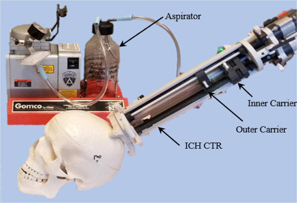
Motivated by the clinical needs and the current technical limitations, we propose the design and evaluation of a skull-mounted MR-conditional CTR made entirely of non-metallic materials for ICH evacuation, as shown in Fig. 1. While 3D-printed tubes have been used in the past for CTRs [30, 31], this paper presents the first use of off-the-shelf plastic tubes. Herein, we discuss the corresponding design, kinematic modeling, and overall system implementation and validation. This paper is arranged in the following way. Section II presents the clinical requirements for the robotic system, the robot hardware design, control algorithm, and the surgical workflow. Section III presents the plastic tube selection and the corresponding kinematic modeling of the variable curvature shape. Section IV presents the experimental setup, procedure, and results. The paper is concluded in Section V.
Fig. 1.
The proposed MR-conditional Concentric Tube Robot (CTR) for ICH treatment.
II. Design, Modeling, and Implementation
A. Clinical Requirements
Commercial ICH evacuation tubes possess an inner diameter ranging from 0.90 to 5 mm for evacuation of hematomas [6, 7, 32–34]. Herein, we elect to use a plastic tube possessing a relatively large inner diameter of 4 mm for the following reasons: (i) improved evacuation efficiency, (ii) elimination of the potential heat risk [29], and (iii) similar stiffness to metallic tubes used previously (Section III–A). It should be noted that while increasing the evacuation vacuum for smaller evacuating tubes can also improve efficiency and provide a less invasive approach, this does not provide the desired stiffness for brain tissue penetration if using plastic tubes with the same diameter. Conventional endoscopes used for delivery of the evacuation tube are generally 10 mm in diameter or less [35, 36]. Thus, to minimize tissue disruption, we also select an outer tube with a comparable outer diameter. Several groups have demonstrated ICH evacuation using CTRs with a radius of curvature (RoC) ranging from 20 to 30 mm and lengths of curvature (LoC) ranging from 27 to 55 mm in the curved portion of the tube [21, 23, 37]. However, their tubes possessed an outer diameter < 2 mm. Due to strain limitations of larger diameters, we elect to minimize the RoC (30 mm) of our tube based on the tube’s material (nylon) and its strain limit (10%) [31]. Additionally, the translational distance requirement of the CTR platform is determined as 85 mm. This is based on the finding that the most common ICH occurs at the basal ganglia [38], which is approximately 85 mm from the frontal bone. It should be noted that in this paper it is desired to obtain a positional accuracy similar to prior CTRs for ICH evacuation (< 2 mm) [23, 24, 39].
B. Mechanical Design Overview
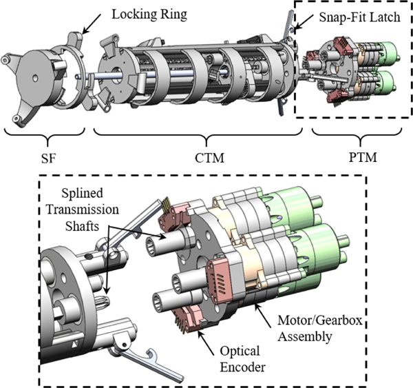
The robotic system is divided into three modular components (Fig. 2). These include: (i) a custom-designed stereotactic frame (SF), (ii) a three DoF concentric tube module (CTM), and (iii) a pneumatic transmission module (PTM). The proposed system is mounted to the patient with three screws via a 3D-printed SF, inspired by state-of-the-art personalized mounting methods [40, 41]. The SF is printed out of polylactic acid (PLA) using a 3D printer (F170, Stratasys, MN, USA). This allows a custom, compact skull mount to be made for a patient within 4 hours after the initial scan, ensuring robust mounting and reducing the time between clinical decompensation and evacuation. Note that although the frame does not include additional DoF, this frame’s compact nature enables entry through an incision anterior to the coronal suture while the patient is in the supine positione in the MRI bore, often the clinician’s predilection for entry in most ICH evacuations [42]. The CTM is linked to the SF using a quarter-turn locking ring. The PTM is coupled to the CTM through a series of plastic locating dowel pins, snap-fit latches, and splined transmission shafts. When aspirating, the inner tube is connected to an aspirator (Gomco Model 300, Allied Healthcare, FL., USA) through a pneumatic union.
Fig. 2.
The ICH CTR in its disassembled state shows three modules. A detailed view of the PTM can be seen.
C. Concentric Tube Module (CTM)
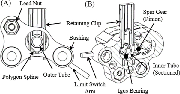
The CTM is made entirely of non-metallic components. The CTM chassis, inner and outer concentric tube carriers, and the inner concentric tube gears are all 3D-printed out of PLA. The CTM prototype is 66 mm in diameter and 242 mm in length. The CTM carriers are translated along carbon fiber rods (OD: 6.35 mm) with Delrin® bushings using plastic translational lead screws. The outer CTM carrier retains a fiberglass outer tube (OD: 7.93 mm, ID: 6.2 mm) using a polygon spline and retaining clip (Fig. 3A). In a similar manner, the inner CTM carrier retains a nylon inner tube (OD: 6 mm, ID: 4 mm). The female polygon spline for the inner tube is embedded into a spur gear (Fig. 3B). The carriers are homed using optical limit switches and the rotational motion of the inner tube is homed using the index pin on a quadrature digital encoder.
Fig. 3.
(A) The outer carrier chassis can be seen holding the outer tube with the polygon spline and retaining clip. (B) In a similar fashion, the inner carrier can be seen holding the inner tube in the sectioned view.
D. Pneumatic Transmission Module (PTM)
MR-conditional actuators can be divided into three categories [45]: (i) piezoelectric actuation (directly driven and cable driven), (ii) hydraulic actuation, and (iii) pneumatic actuation. This work elects to use pneumatic actuation as the joint-space actuation modality for enumerated reasons. (i) Pneumatic actuation eliminates the magnetic interference that often precludes synchronous imaging and motor operation in piezoelectric actuation [46]. (ii) Pneumatic actuation permits direct placement of the motor output shaft at the driven component. This prevents feedback corruption caused by backlash and hysteresis specific to the separation of the motor encoder feedback from the cable-driven robotic system. (iii) Pneumatic actuation can be provided by sterile air from the MRI room, avoiding the risk of compromising the sterile environment caused by leaking hydraulic actuation [45]. The PTM consists of three pneumatic bi-directional radial inflow turbines (Fig. 2), which were modified from our prior work [46]. Each motor is driven by two 10-m pneumatic lines routed through the MRI waveguide allowing bi-directional rotation. The long pneumatic lines are a unique feature of this motor, allowing decoupling of the electromagnetic interaction between the mechatronic devices and the MRI. Conversely, other pneumatic actuators often require pneumatic tubing less than three meters and the use of Faraday’s cages in the MRI room to eliminate image artifacts or safety concerns [47].
E. Mechatronic Hardware and Motor Control
The pneumatic motors are controlled using a 16-bit DMC-4163 Galil Motion Controller (DMC-4163, Galil, CA, USA). The flow to the motors is regulated using 5/3 normally closed pneumatic flow control valves (MPYE-5-M5–010-B, Festo, US). The DMC-4163 normally operates with constant user-defined PID values. However, our system has two contradictory complexities that preclude the implementation of standard PID.
Our turbine motors have a high nominal speed (45,000 rpm). Consequently, a large gear reduction must be used (≥100:1). As a result, the friction induced by the plastic gearbox cause a significant dead-band region and requires a high proportional gain to overcome the dead-band region.
Our imaging modality requires long pneumatic lines, which introduces a significant delay. Thus, steady-state oscillation is exhibited with high proportional gains.
In order to efficiently operate the motor and maintain the accuracy required by the clinical requirements, a control law was developed that modifies the proportional gain as a function of the error and motor state. This control algorithm is inspired by MATLAB state machines and is summarized as follows:
| (1) |
where is the proportional gain of the controller as a function of error, , and rotational speed, , is the acceptable error tolerance is the upper error bound for transitioning between a constant proportional gain (Region III) and a variable proportional gain (Region II), is the minimum voltage signal necessary to move the motor when rotational velocity is zero, and is the minimum voltage signal necessary to avoid the dead-band region as the motor approaches the target in Region II with a non-zero rotational velocity. The integral gain was to avoid a lagging behavior introduced by integral gains and the derivative gain was (the controller maximum).
F. Intraoperative MR Imaging and Clinical Workflow
The MR-guided intervention was performed in a 70 cm wide bore, Philips 3 Tesla Ingenia Elition MRI System with a 2-channel body transmit/2-channel flex coil receive setup. The robot and clot were localized using 3D scout imaging and MR visible fiducials placed on the SF. The robot was registered using rigid-body registration. Dynamic images were taken at the region of interest (ROI) using single slice spoiled gradientecho imaging: FOV 240×240 mm2, 1×1 mm2 resolution, TR/TE = 5/2 ms, and a dynamic scan time of 1 s/image. Prior to the robot performing a move to a target, the inverse kinematics are used to calculate the rotational angle of the inner tube in the robot frame, and the imaging plane is set to correspond to this angle, ensuring the curved inner tube motion can be monitored via real-time image feedback.
As part of providing a comprehensive discussion on our system implementation, we propose the following workflow.
Perform a preoperative scan to localize the clot. The clinician will define an insertion path based on the scan.
Select a set of pre-fabricated inner tubes with different curvatures to evacuate the complex hematoma topology.
Print the SF based on the clinician-defined path.
Mount the SF and use it as a guide for drilling the burr hole.
Transfer the patient to the MRI room for evacuation.
Connect the robot to the workstation and home the robot.
Mount the robot to the SF from the superior end of the MRI bore and register it to the MRI’s coordinate system. Locate the clot in the robot coordinate frame.
Initiate dynamic imaging for CTR insertion monitoring.
Evacuate the hematoma under MRI guidance until an acceptable residual hematoma remains.
Home the robot and remove the robot and SF.
III. Plastic Tube Selection and Modeling
A. CTR Tube Selection
CTRs are typically fabricated with nitinol materials. However, our specified clinical requirements (minimize the MR-imaging artifact) of this project limit the scope of material selection to plastic materials with low elastic moduli (< 8 GPa), and consequently, larger inner diameters. This is justified by considering the tube used in our prior work [48]. The tube used was nitinol with the design parameters shown in Table 1 row 1. Using our force analysis model (Sec III–C), these design parameters result in a total force of 111.84 N needed to bend the tube into a straight configuration. Using nylon, a tube with the same design parameters as [48] requires only a total force of 4.96 N to bend the tube into a straight configuration. Note that this results in a tube with insufficient stiffness for the procedure. However, if the nylon tube matches our diametral dimensions, the total force to bend the tube into a straight configuration is 107.44 N (Table I). This analysis illustrates the need for larger plastic tubes for our clinical requirements. Herein, we use off-the-shelf, highly elastic nylon tubing for the inner tube with an outer diameter of 6 mm and inner diameter of 4 mm (50405K35, McMaster-Carr, GA, USA).
Table 1.
Comparison of Bending Stiffness to Tube Properties
Plastic materials provide the unique advantage of a lower heat-setting temperature. This allows the ability to fabricate patient-specific curved tubes based on the pre-operative scan. To validate this concept, a heat gun is brought to a temperature of 350 °C and the plastic tube is heated for 30 seconds. Then the tube is placed in a fixture defining the desired RoC. This tube is allowed to sit for 3 minutes in the fixture and is then removed and cooled under running water, setting the tube shape.
It should be noted that spring-back, the tendency of a bent elastic material to revert to its original form after shaping, is a prevalent issue during the heat-setting process of any material [49]. To validate whether the inner tube can retain the pre-shaped configuration during operation, the inner tube prototype was shape-set with a desired RoC of 30 mm. This was done by first shape-setting the tube with a RoC (20 mm) smaller than the minimum RoC (30 mm). The tube was then placed inside the outer tube for 1 hour after cooling. The 1-hour straightening is meant to induce spring-back. Following straightening, an image was taken and it was found that an average RoC of 32.4 mm was obtained. The tube was then cycled in and out of the outer tube for 1000 cycles with a translational lead-screw mechanism after shape setting. An image was taken after cycling and the resulting average RoC of the inner tube was calculated as 33.4 mm. Note that this resulted in a maximum difference in the tip position before and after the cycling of 0.38 mm. Thus, we conclude that for a single ICH procedure, the nylon tube can sufficiently retain its shape.
B. Forward Kinematics
In this work, it was observed that the plastic presented variability in curvature across the length of the tube after shape-setting. Thus, a constant curvature approach cannot be used directly. Herein, we use a discretized, piece-wise constant curvature (D-PCC) model for the proposed tube. Note that we assume the outer tube possesses zero curvature and a sufficiently high elastic and torsional modulus.
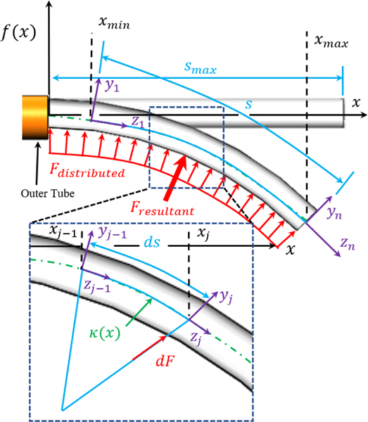
The model begins by first representing the inner tube’s shape as a function (Fig. 4). The inner tube’s first- and second-order derivatives are considered continuous, as the inner tube continuously bends. Thus, the curvature and arc length at any point along the function can be defined by
| (2) |
| (3) |
where and are the first and second derivative of the function, is the independent variable of the function, is the curvature of the function at some point , and and are the lower and upper bounds of integration used to determine the arc length for a discrete segment of the function.
Fig. 4.
The modeling strategy can be seen superimposed on a pre-curved tube of arbitrary shape defined by . The modeling strategy for analyzing torsion can also be seen. Herein, the distributed load (red) applied across the inner tube’s body is divided into discrete elements. Note that the force of the discrete segment is applied at the distal end while the proximal end is assumed fixed to ground, isolating the discrete segment.
Obtaining tube shape with respect to the insertion depth requires the lower and upper limits of . The upper limit of occurs at the distal tip of the tube, which is . However, the lower bound of integration decreases with increasing . We solve for numerically by driving the left-hand side of (4) to zero using the fzero() function in MATLAB.
| (4) |
Using (2) and (3), the change in shape of a discrete element of can be represented by the transformation matrix
| (5) |
Assuming that for an infinitesimal segment of the tube the curvature is constant, the tube can be discretized into points and the total shape of the tube given an insertion depth is
| (6) |
where is defined by
| (7) |
Thus, the CTR’s full configuration is
| (8) |
where is defined as the transformation matrix caused by outer tube extension and inner tube rotation [23].
C. Torsional Modeling
When the inner tube is inside the outer tube, the force applied by the outer tube that straightens the inner tube produces a resistive torque when the inner tube is rotated, resulting in a tip position RMSE as high as 1 mm from torsional displacement alone. In this section, we develop a mechanics-based model that compensates for the torsional deflection of the inner tube. We again use a function to describe the inner tube’s shape.
We begin by considering a discrete section of the tube bent with curvature as a cantilever beam and calculate the force necessary to straighten the discrete section, as shown in Fig. 4. We define the strain energy in this discrete section of the tube using Castigliano’s first theorem, which can be written as [50]
| (10) |
where is strain energy stored in the system, is the curvature of the tube, is the force applied to change the curvature of the discrete segment, and is the moment arm of the applied force. To solve for the strain energy associated with a discrete section of the tube, it is first recognized that the strain in an axial fiber of any cross-section based on curvature can be defined as [51]
| (11) |
where is the distance from a coordinate system defined in the cross-section of the rod and is the distance of the neutral bending plane from the same coordinate system. Using (11), the strain energy density within an axial fiber of the discrete section is equal to the area under the stress-strain curve of that fiber
| (12) |
where is the strain energy density as a function of strain and curvature, as defined by (11) and (2), and the stress . Thus, the strain energy induced by straightening a segment from its precurved configuration can be defined as
| (13) |
where and are the outer and inner radius of the inner tube and the length of the discretized segment. Using (13), we can rewrite (10) in its discretized form to find the force applied to that segment as
| (14) |
where is the moment arm. Using (14), the sum of all the discrete forces, i.e. the distributed load applied to the deflectable region of the inner tube when inside the outer tube, can be written as a function of insertion depth s as
| (15) |
where is the number of discrete segments and is defined as
| (16) |
where this section increases with insertion depth. can be numerically solved for by driving the left-hand side of the following to zero
| (17) |
It should be noted that (15) is the resultant force of the distributed load applied to the inner tube’s surface by the outer tube. By considering the resultant force to occur at a single point, the resistive torque can be solved for as
| (18) |
where is the torque applied to the tube and is the coefficient of static friction between the inner and outer tube, 0.17 in this case. However, before torsional deflection can be evaluated, the location of the resultant force must be determined, which can be expressed as [50]
| (19) |
where is the location of the resultant force. Note that occurs at the proximal end of the deflectable region of the inner tube. Using (18) and (19), the angular deflection caused by an applied torque is
| (20) |
where is the angular deflection in radians between the base of the inner tube (at the polygon spline) and the location of the resultant force, is the total length of the inner tube, is the polar second moment of inertia, and is the shear modulus of the inner tube. Using , the torsional deflection of the inner tube can be compensated, improving targeting accuracy.
IV. Experimental Procedure and Results
A. MR-conditional Pneumatic Motor Control
The pneumatic motor performance was evaluated with the robot in its assembled state, ensuring that system dynamics were included while characterizing the voltage values. The motors were driven using a compressor (8010, California Air, CA., USA) with a supply pressure of 90 psi. The starting voltage was measured by incrementing the signal voltage by 0.1 V, starting at 0 V. The voltage value corresponding to a non-zero rotational velocity was recorded as . In a similar fashion, was measured by incrementing the signal voltage by −0.1 V, starting at . The voltage value prior to zero rotational velocity was recorded as (i.e. if the motor stops rotating at 2.9 V, ). This was done for both clockwise and counter-clockwise rotation of the motor. For the motors controlling the translational axes, and . For the motor controlling the rotational axis of the inner tube, and . These parameters resulted in a motor accuracy of 0.32°±0.30° at the gearbox output shaft, which is an improvement on our prior work (1° error) [46].
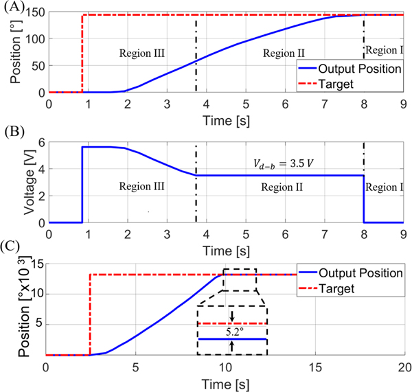
An example of the motor used for the rotational DoF (gear reduction of 2500:1) transitioning between the constant PID and variable portion of the control law region during the MR-guided experiment can be seen in Fig. 5A. A set point of 144° was prescribed at . The motor began to respond at 1.56 s and obtained a steady state error of zero at . The corresponding voltage signal provided by the control law is seen in Fig. 5B. It should be noted that the motor used to control the translational DoF use a 100:1 gear reduction (as shown in Fig. 5C), significantly increasing motor speed (resulting in a rotational speed of 302 rpm at the output shaft of the gearbox and a translational speed of ~4 mm per second). This provides an improved speed over state-of-the-art piezoelectric motors (LR17 of 44 rpm, LR23–50 of 27 rpm, and LR23–80 of 27 rpm, all made by Faulhaber [47]), as well as current pneumatic based-actuators, such as 15 rpm in [52] and 70 rpm in [53]. Note that Fig. 5C depicts a motor with a (i.e. not the characterized 3.0V) for the translational DoF, and the resulting dead-band position can be seen (~5° error). However, it should be noted that 5° error for the translational DoF corresponds to a translational error of <0.01 mm.
Fig. 5.
(A) The motor’s response to a setpoint of 144° with a resulting steady-state error of 0°. (B) The voltage signal supplied to the motor. The constant voltage in Region II is due to the control-law varying gain used to maintain a voltage level above the dead-band region. (C) The response of the translational motor can also be seen with a less than the characterized value. The resulting 5.2° error can be seen, showcasing the need for using the characterized dead-band voltage.
B. Kinematic Model Validation
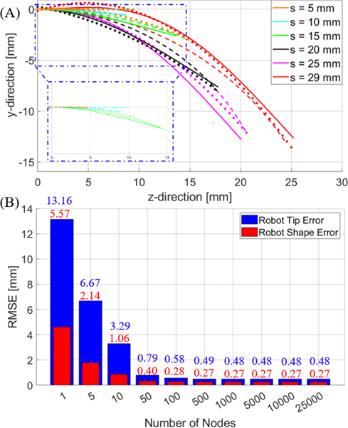
The kinematic model was validated first in 2D using a camera (5WH00002, Microsoft, USA) placed perpendicular to the longitudinal axis of the robot. The inner tube’s shape was characterized with the inner tube at an insertion depth of 29 mm (maximum insertion depth difference) with respect to the outer tube. A single picture of the tube was taken and a 4th order polynomial was fitted to the center-line of the tube shape. The inner tube was then configured with an initial insertion depth of 0 mm with respect to the outer tube (fully retracted), and inserted in increments of 1 mm up to 29 mm. At each increment, an image of the tube shape was recorded and points were selected along the center-line of the tube to obtain the experimental tube shape at each insertion depth. The model was then used to predict the tube shape at each increment. Examples of the tube shape using the model can be seen in Fig. 6A. Additionally, the model accuracy with respect to the number of nodes constructing the tube can be seen in Fig. 6B. Note that the model accuracy plateaus at approximately 100 nodes (the number of nodes used for evaluating accuracy in Table 2).
Fig. 6.
(A) depicts the tube shape for different insertion depths calculated using the model (solid line). The dots represent the image locations corresponding to the tube centerline and the dashed line represents the piece-wise constant curvature assumption evaluation for different insertion depths with tip error minimization. (B) Error bars representing the average RMSE of the robot tip (blue) and shape (red) of the model based on the number of nodes across all insertion depths tested (i.e. 1 mm to 29 mm in 1 mm increments).
Table 2.
In-Plane Comparison of the Constant Curvature and Characterization Modeling Approaches
| Insertion Depth [mm] | RoC [mm] (PCC) | Tip RMSE [mm] (PCC) | Robot Shape RMSE [mm] (PCC) | Tip RMSE [mm] (D-PCC (Our Method)) | Robot Shape RMSE [mm] (D-PCC (Our Method)) |
|---|---|---|---|---|---|
|
| |||||
| 9.52e03 | 0.02 | 0.02±0.01 | 0.03 | 0.01±0.01 | |
| 9.52e03 | 0.56 | 0.03±0.02 | 0.83 | 0.23±0.16 | |
| 38.32 | 0.22 | 0.17±0.09 | 0.16 | 0.33±0.20 | |
| 23.58 | 0.24 | 0.61±0.40 | 0.63 | 0.24±0.13 | |
| 23.49 | 0.03 | 0.51±0.39 | 0.95 | 0.47±0.46 | |
| 29.36 | 0.60 | 0.81±0.45 | 1.08 | 0.32±0.24 | |
| Average | ~ | 0.26 | 0.37 | 0.58 | 0.28 |
The results of the model and the piecewise constant curvature assumption at each insertion depth were both compared to the experimental images. The curvature for the piecewise constant curvature (PCC) (with respect to insertion depth) plot values were obtained by minimizing the error between the constant curvature assumption and the experimentally measured tip value using MATLAB’s fminsearch(). Table 2 presents the results of the two models compared to the experimental results. Note that the “Average” row represents the average RMSE for all insertion depths from 1 mm to 29 mm in 1 mm increments. The metrics of comparison were the average RMSE of the tip position of the tube and the average RMSE of the tube’s shape. The RMSE of the tube’s shape is defined as the average of the minimum RMSE at 1 mm increments along the tube’s body.
For example, at , the minimum RMSE between the model and the experiment would be calculated 10 times, one for each 1 mm increment, and then averaged. Note that while the model results are comparable, the PCC model requires a priori knowledge of the tip position at each insertion depth (e.g. one image per desired insertion increment), as the shape is unknown. This does potentially improve tip accuracy, as the curvature value selected is obtained by minimizing the error of the tip position. Conversely, our model (D-PCC) obtains the tube shape based on a continuous function with a single image and improves the tube shape results.
C. Free-Space Modeling Validation
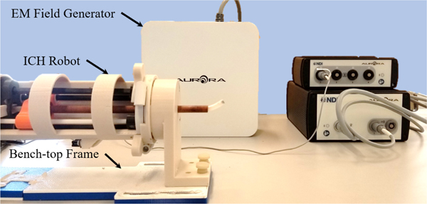
A set of experiments were performed in free-space to validate the model and robotic system in 3D (Fig. 7). The inner tube’s tip position was recorded using an Electro-Magnetic (EM) field generator (Aurora, NDI Medical, Ontario, Canada). The robot was rigidly mounted to the table and its coordinate frame was registered to the tracker coordinate frame through the point-based registration method. Forty-eight target points were randomly selected in the robot’s coordinate frame. The x and y target locations ranged between 8 and −8 mm results in ) and the z target location varied between 20 and 70 mm. The robot was able to maintain a targeting RMSE of 1.39±0.54 mm, which is an improvement over the case when torsion is not considered (RMSE 1.66±0.91 mm for forty-eight additional points). Note that this average RMSE is comparable to CTRs that use metallic tubes (1.26 mm in [23], 1.73 mm in [24], and 1.00 mm in [39]).
Fig. 7.
Bench-top setup used to validate the robot’s kinematic model.
D. Robot MR-conditionality and MRI Tube Artifact
MR-conditionality was validated using 3D T1 weighted imaging (Fig. 8A). A bottle water-phantom was located at the isocenter of the MRI scanner and a region of interest (ROI) within the bottle was compared under two scenarios: (i) no robot in the MRI-scanner, and (ii) robot operating in the MRI-scanner. There was less than 1% change in signal to noise ratio (SNR) for both the robot off and robot operating conditions.
Fig. 8.
(A) T1-weight images of the bottle phantom can be seen (left to right) with no robot and the robot turned on and operating. (B) The outer tube, inner tube, and nitinol tube can be seen inside a water phantom in the coronal plane of the MRI. There was a percent increase of 2.14%, 6.07%, and 440% for the outer tube (initial OD: 7.93 mm), inner tube (initial OD: 6.00 mm), and nitinol tube (initial OD: 3.00 mm), respectively.
An imaging experiment was performed to provide a comparison of the signal void artifact produced by the selected plastic (6 mm OD) and fiberglass (7.93 mm OD) tubes to a nitinol tube (3 mm OD). 3D spoiled gradient-echo imaging (FOV: 240×240×240 mm3, 0.9×0.9 mm2 resolution, TR/TE = 5/2 ms) was performed to visualize the tube artifacts, as shown in Fig. 8B. The size of the artifact was then compared to the original tube’s size. The artifact of the outer fiberglass tube, inner plastic tube, and sample nitinol tube each had a percent increase of 2.14%, 6.07%, and 440%, respectively, compared to their original diameter. This indicates the need for non-metallic tubes for ICH evacuation with MR-guided procedures.
E. MRI Targeting Accuracy Characterization
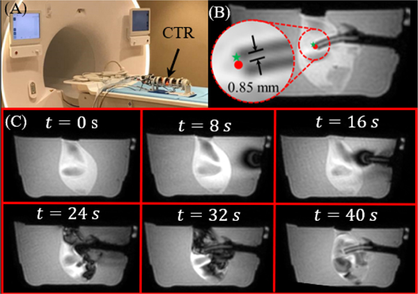
The robot’s tip accuracy was validated in the same scanner using a 10% by weight KnoxTM (Kraft Foods Global, Inc., USA) gelatin phantom (Fig. 9A). During the experiment, the phantom was placed in front of the robot with a pair of flexible imaging coils on either side of the phantom. The robot was first localized using MR visible fiducials (PinPoint® #128, Beekley, USA). Following localization, ten target locations were selected at different depths around the rotational axis of the inner tube in the MR coordinate system. These targets were converted to the robot’s coordinate frame and inverse kinematics were used to determine the joint space parameters needed to reach the target. Dynamic imaging (1 Hz) was performed (Fig. 9C) for visualization and accuracy validation. The accuracy was quantified based on the RMSE between the desired location and the robot’s final location, resulting in an average two-dimensional RMSE and standard deviation of 0.85±0.16 mm. It should be noted that the error is presumably lower for the MRI experiment due to the assumption that the center-line of the tube is in plane with the MRI’s 2D slice, as shown in Fig. 9B. However, the artifact of the tube in each 2D slice had an outer diameter of 6 mm, suggesting that the centerline of the tube lies in the slice plane.
Fig. 9.
(A) The robot in the MRI room. (B) An example of one dynamic slice can be seen with error between the target point (green star) and the tip position (red dot) superimposed on the image. (C) A time sequence of the inner tube entering from start to finish in the sagittal plane. Image intensity variations within the clot originate from artifacts caused by fluid flow.
F. MR-Guided Phantom Clot Evacuation
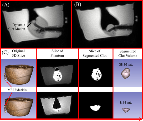
The clot evacuation efficiency was first tested in a phantom trial using a 10% by weight Knox™ (Kraft Foods Global, Inc., USA) gelatin phantom. The phantom was filled with a congealed artificial clot substitute that provided high contrast during MR-imaging, resulting in a 38.36 mL clot (Fig. 10A–B). The experimental setup was identical to the MRI phantom accuracy characterization; however, target points were periodically selected to evacuate the clot. After the procedure, the clot was segmented using 3D Slicer [54]. The resulting segmentation can be seen in Fig. 10C. The evacuation procedure lasted only 5 minutes under dynamic imaging, which is 10 times faster compared to our prior work. This is primarily due to the increased aspiration tube dimension. Note that this high-efficiency evacuation can be particularly beneficial for patients with acute hemorrhage, as physicians aim to evacuate the hematoma quickly to release the intracranial pressure, preserving brain tissue.
Fig. 10.
(A) The tube can be seen within the phantom at the start of the evacuation procedure and (B) after the evacuation procedure. Note that (A) and (B) show the aspiration tube reaching two different target points during the procedure. (C) 3D scan was performed before and after the procedure and the clot volume was segmented to show the evacuation outcome.
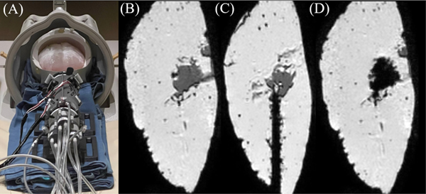
As part of developing a comprehensive evaluation of the robot, five additional artificial hematomas were evacuated under MR-guidance to identify unanticipated failure patterns of the robot. These include two gelatin-based phantoms, one with a water-based hematoma and one with a congealed artificial clot; and three Mount Sinai hydrogel brain phantoms (Fig. 11 A–D), two with a gelatinous hematoma and one with a congealed artificial clot substitute. Several observations were made that indicate potential for system improvement. One concern was the absence of a cutting edge provided by obturator often used for delivery into the brain in manual evacuation [35]. Inclusion of a similar obturator would enable easy penetration into the brain. Another concern is clot viscosity. For example, using the aspirator shown in Fig. 1, the robot can easily evacuate a hematoma made of water or gel. However, our congealed artificial clot was significantly thicker, and requires higher vacuum to prevent clogging of the tube (>150 mmHg available in MRI scanner room). As a final note, for the clot volumes investigated in this work (near the basal ganglia and < 50 mL in volume), the workspace of the robot was sufficient for evacuation (Fig. 11B–D). However, future studies will investigate optimization of tube geometry selection.
Fig. 11.
(A) Robotic system with Mount Sinai brain phantom. (B) Clot prior to evacuation. (C) CTR inside brain phantom. (D) Clot after evacuation. The black region inside the brain indicates the hollow cavity after clot evacuation.
V. Conclusions
In this article, we present the design and fabrication, mechanics modeling, and targeting validation of a CTR for MR-guided ICH evacuation. This article presents the first-ever use of off-the-shelf plastic tubes for CTR. Due to the variable curvature of these tubes and the low shear modulus of plastic, a new model was developed to analyze the kinematics. This model used a single image of the inner tube at its maximum insertion displacement from the outer tube to characterize the shape of the inner tube. The kinematics were then used in MR-guided evacuation, showcasing the robot’s evacuation efficiency. This work suggests plastic tubes can be effectively used for MR-guided ICH evacuation. Future work will investigate the development of a multi-DoF targeting frame for robot alignment, increasing functionality. Additionally, we aim to thoroughly investigate the modeling and control of the pneumatic motor.
Supplementary Material
ACKNOWLEDGMENT
The authors would like to thank Dylan Kingsbury and the team at Galil for their tireless assistance.
This research is funded by NIH R01 NS116148.
Contributor Information
Anthony L. Gunderman, Biomedical Engineering Department, Georgia Institute of Technology/Emory, Atlanta 30338 USA
Saikat Sengupta, Vanderbilt University Institute of Imaging Science, Vanderbilt University Medical Center, Nashville, TN 37232 USA.
Eleni Siampli, Sheikh Zayed Institute for Pediatric Surgical Innovation, Children’s National Hospital, Washington, DC 20010 USA.
Dimitri Sigounas, The George Washington University School of Medicine and Health Sciences, Department of Neurosurgery, George Washington University, Washington, DC, US.
Christopher Kellner, Department of Neurosurgery, Icahn School of Medicine at Mount Sinai, New York, New York.
Chima Oluigbo, Sheikh Zayed Institute for Pediatric Surgical Innovation, Children’s National Hospital, Washington, DC 20010 USA.
Karun Sharma, Sheikh Zayed Institute for Pediatric Surgical Innovation, Children’s National Hospital, Washington, DC 20010 USA.
Isuru Godage, Robotics and Medical Engineering (RoME) Laboratory, School of Computing, DePaul University, Chicago, IL 60604, USA..
Kevin Cleary, Sheikh Zayed Institute for Pediatric Surgical Innovation, Children’s National Hospital, Washington, DC 20010 USA.
Yue Chen, Biomedical Engineering Department, Georgia Institute of Technology/Emory, Atlanta 30338 USA.
REFERENCES
- [1].WHO. “The Top 10 Causes of Death.” World Health Organization. https://www.who.int/news-room/fact-sheets/detail/the-top-10-causes-of-death#:~:text=Since%202000%2C%20the%20largest%20increase,6%25%20of%20total%20deaths%20respectively (accessed February 12, December 9, 2022). [Google Scholar]
- [2].Wang WJ, Zhou NQ, and Wang C, “Minimally Invasive Surgery for Patients with Hypertensive Intracerebral Hemorrhage with Large Hematoma Volume: A Retrospective Study,” World Neurosurg, vol. 105, pp. 348–358, Sep 2017, doi: 10.1016/j.wneu.2017.05.158. [DOI] [PubMed] [Google Scholar]
- [3].Mendelow AD, Gregson BA, Fernandes HM, Murray GD, Teasdale GM, Hope DT, Karimi A, Shaw MDM, Barer DH, and Investigators S, “Early surgery versus initial conservative treatment in patients with spontaneous supratentorial intracerebral haematomas in the International Surgical Trial in Intracerebral Haemorrhage (STICH): a randomised trial,” Lancet, vol. 365, no. 9457, pp. 387–397, Jan-Feb 2005. [Online]. Available: <Go to ISI>://WOS:000226610900025. [DOI] [PubMed] [Google Scholar]
- [4].Carhuapoma JR, Barrett RJ, Keyl PM, Hanley DF, and Johnson RR, “Stereotactic aspiration-thrombolysis of intracerebral hemorrhage and its impact on perihematoma brain edema,” Neurocritical care, vol. 8, no. 3, pp. 322–329, 2008. [DOI] [PMC free article] [PubMed] [Google Scholar]
- [5].Rigante L, Borghei-Razavi H, Recinos PF, and Roser F, “An overview of endoscopy in neurologic surgery,” Clev Clin J Med, vol. 86, no. 10, Oct 2019, doi: 10.3949/ccjm.86.me.18142. [DOI] [PubMed] [Google Scholar]
- [6].Wang W-H, Hung Y-C, Hsu SP, Lin C-F, Chen H-H, Shih Y-H, and Lee C-C, “Endoscopic hematoma evacuation in patients with spontaneous supratentorial intracerebral hemorrhage,” Journal of the Chinese Medical Association, vol. 78, no. 2, pp. 101–107, 2015. [DOI] [PubMed] [Google Scholar]
- [7].Fukuhara A, Tsujita T, Sase K, Konno A, Nakagawa A, Endo T, Tominaga T, Jiang X, Abiko S, and Uchiyama M, “Securing an optimum operating field without undesired tissue damage in neurosurgery,” Advanced Robotics, vol. 30, no. 19, pp. 1245–1259, 2016. [Google Scholar]
- [8].Pacheco NE, Gafford JB, Atalla MA, Webster RJ III, and Fichera L, “Beyond Constant Curvature: A New Mechanics Model for Unidirectional Notched-Tube Continuum Wrists,” Journal of Medical Robotics Research, 2021. [DOI] [PMC free article] [PubMed] [Google Scholar]
- [9].Gunderman AL, Schmidt EJ, Morcos M, Tokuda J, Seethamraju RT, Halperin HR, Viswanathan AN, and Chen Y, “MR-Tracked Deflectable Stylet for Gynecologic Brachytherapy,” IEEE/ASME Transactions on Mechatronics, 2021. [DOI] [PMC free article] [PubMed] [Google Scholar]
- [10].Gunderman AL, Schmidt EJ, Viswanathan AN, Halperin HR, Tokuda J, Seethamraju RT, and Chen Y, “MR-Guided Tissue Puncture with On-Line Imaging for HighResolution Theranostics,” presented at the International Symposium on Medical Robotics Georgia Tech, 2020. [Google Scholar]
- [11].Li YC, Liu Y, Yamazaki K, Bai MF, and Chen Y, “Development of a Soft Robot Based Photodynamic Therapy for Pancreatic Cancer,” IEEE-ASME Transactions on Mechatronics, vol. 26, no. 6, pp. 2977–2985, Dec 2021, doi: 10.1109/Tmech.2021.3049354. [DOI] [Google Scholar]
- [12].Yan JY, Chen JB, Chen JF, Yan WQ, Ding QP, Yan K, Du JX, Lam CP, Wong GKC, and Cheng SS, “A Continuum Robotic Cannula With Tip Following Capability and Distal Dexterity for Intracerebral Hemorrhage Evacuation,” IEEE Transactions on Biomedical Engineering, vol. 69, no. 9, pp. 2958–2969, Sep 2022, doi: 10.1109/Tbme.2022.3158539. [DOI] [PubMed] [Google Scholar]
- [13].Engh JA, Podnar G, Kondziolka D, and Riviere CN, “Toward effective needle steering in brain tissue,” 2006 28th Annual International Conference of the IEEE Engineering in Medicine and Biology Society, Vols 1–15, pp. 3383-+, 2006. [Online]. Available: <Go to ISI>://WOS:000247284703214. [DOI] [PubMed] [Google Scholar]
- [14].Kim Y, Cheng S, Diakite M, Gullapalli RP, Simard JM, and Desai JP, “Toward the Development of a Flexible Mesoscale MRI-Compatible Neurosurgical Continuum Robot,” IEEE Transactions on Robotics, vol. vol. 33, no. 6, pp. 1386–1397, 2017, doi: 10.1109/TRO.2017.2719035. [DOI] [PMC free article] [PubMed] [Google Scholar]
- [15].Kim Y, Cheng SS, and Desai JP, “Towards the Development of a Spring-based Continuum Robot for Neurosurgery,” Medical Imaging 2015: Image-Guided Procedures, Robotic Interventions, and Modeling, vol. 9415, 2015, doi: Artn 10.1117/12.2082193. [DOI] [Google Scholar]
- [16].Sheng J. and Desai JP, “Towards a SMA-actuated Neurosurgical Intracerebral Hemorrhage Evacuation (NICHE) robot,” IEEE/RSJ International Conference on Intelligent Robots and Systems (IROS), pp. 3805–3810, 2015, doi: 10.1109/IROS.2015.7353911. [DOI] [Google Scholar]
- [17].Mahoney AW, Gilbert HB, and Webster III RJ, “A review of concentric tube robots: modeling, control, design, planning, and sensing,” in The Encyclopedia of MEDICAL ROBOTICS: Volume 1 Minimally Invasive Surgical Robotics vol. 1, ed, 2019, pp. 181–202. [Google Scholar]
- [18].Bruns TL, Remirez AA, Emerson MA, Lathrop RA, Mahoney AW, Gilbert HB, Liu CL, Russell PT, Labadie RF, Weaver KD, and Webster RJ, “A modular, multi-arm concentric tube robot system with application to transnasal surgery for orbital tumors,” International Journal of Robotics Research, vol. 40, no. 2–3, pp. 521–533, Feb 2021, doi: 10.1177/02783649211000074. [DOI] [Google Scholar]
- [19].Rox MF, Ropella DS, Hendrick RJ, Blum E, Naftel RP, Bow HC, Herrell SD, Weaver KD, Chambless LB, and Webster RJ, “Mechatronic Design of a Two-Arm Concentric Tube Robot System for Rigid Neuroendoscopy,” IEEE-ASME Transactions on Mechatronics, Article vol. 25, no. 3, pp. 1432–1443, JUN 2020. 2020, doi: 10.1109/TMECH.2020.2976897. [DOI] [PMC free article] [PubMed] [Google Scholar]
- [20].Zhu YF, Swaney PJ, Godage IS, Lathrop RA, and Webster RJ, “A Disposable Robot for Intracerebral Hemorrhage Removal,” Journal of Medical Devices-Transactions of the ASME, vol. 10, no. 2, Jun 2016, doi: Artn 10.1115/1.4033246. [DOI] [Google Scholar]
- [21].Godage IS, Remirez AA, Wirz R, Weaver KD, Burgner-Kahrs J, and Webster RJ, “Robotic Intracerebral Hemorrhage Evacuation: An InScanner Approach with Concentric Tube Robots,” 2015 IEEE/Rsj International Conference on Intelligent Robots and Systems (Iros), pp. 1447–1452, 2015. [Online]. Available: <Go to ISI>://WOS:000371885401089. [Google Scholar]
- [22].Ronckers CM, Land CE, Miller JS, Stovall M, Lonstein JE, and Doody MM, “Cancer Mortality among Women Frequently Exposed to Radiographic Examinations for Spinal Disorders,” Radiat Res, vol. 174, no. 1, pp. 83–90, Jul 2010, doi: 10.1667/Rr2022.1. [DOI] [PMC free article] [PubMed] [Google Scholar]
- [23].Chen Y, Godage IS, Sengupta S, Liu CL, Weaver KD, and Barth EJ, “MR-conditional steerable needle robot for intracerebral hemorrhage removal,” International journal of computer assisted radiology and surgery, vol. 14, no. 1, pp. 105–115, 2019. [DOI] [PMC free article] [PubMed] [Google Scholar]
- [24].Chen Y, Godage IS, Sengupta S, Liu CL, Weaver KD, Barth EJ, and Webster RJ, “An MRI-Compatible Robot for Intracerebral Hemorrhage Removal,” presented at the Proceedings of the 2017 Design of Medical Devices Conference. 2017 Design of Medical Devices Conference, Minneapolis, Minnesota, USA, 2017. [Google Scholar]
- [25].Sengupta S, Yan X, Hoyt TL, Drake G, Gunderman A, and Chen Y, “Minimal artifact actively shimmed metallic needles in MRI,” Magn Reson Med, vol. 87, no. 1, pp. 541–550, Jan 2022, doi: 10.1002/mrm.28977. [DOI] [PMC free article] [PubMed] [Google Scholar]
- [26].Konings MK, Bartels LW, Smits HFM, and Bakker CJG, “Heating around intravascular guidewires by resonating RF waves,” Journal of Magnetic Resonance Imaging, vol. 12, no. 1, pp. 79–85, Jul 2000, doi: Doi . [DOI] [PubMed] [Google Scholar]
- [27].Nitz WR, Oppelt A, Renz W, Manke C, Lenhart M, and Link J, “On the heating of linear conductive structures as guide wires and catheters in interventional MRI,” Journal of Magnetic Resonance Imaging, Article vol. 13, no. 1, pp. 105–114, JAN 2001. 2001, doi: . [DOI] [PubMed] [Google Scholar]
- [28].Ryu SC, Quek ZF, Koh JS, Renaud P, Black RJ, Moslehi B, Daniel BL, Cho KJ, and Cutkosky MR, “Design of an Optically Controlled MR-Compatible Active Needle,” IEEE Transactions on Robotics, vol. 31, no. 1, pp. 1–11, Feb 2015, doi: 10.1109/Tro.2014.2367351. [DOI] [PMC free article] [PubMed] [Google Scholar]
- [29].Alipour A, Meyer ES, Dumoulin CL, Watkins RD, Elahi H, Loew W, Schweitzer J, Olson G, Chen Y, Tao S, Guttman M, Kolandaivelu A, Halperin HR, and Schmidt EJ, “MRI Conditional Actively Tracked Metallic Electrophysiology Catheters and Guidewires With Miniature Tethered Radio-Frequency Traps: Theory, Design, and Validation,” IEEE Transactions on Biomedical Engineering, Article vol. 67, no. 6, pp. 1616–1627, JUN 2020. 2020, doi: 10.1109/TBME.2019.2941460. [DOI] [PMC free article] [PubMed] [Google Scholar]
- [30].Amanov E, Nguyen TD, and Burgner-Kahrs J, “Additive Manufacturing of Patient-Specific Tubular Continuum Manipulators,” Medical Imaging 2015: Image-Guided Procedures, Robotic Interventions, and Modeling, vol. 9415, 2015, doi: Artn 10.1117/12.2081999. [DOI] [Google Scholar]
- [31].Morimoto TK and Okamura AM, “Design of 3-D Printed Concentric Tube Robots,” IEEE Trans Robot, vol. 32, no. 6, pp. 1419–1430, Dec 2016, doi: 10.1109/TRO.2016.2602368. [DOI] [PMC free article] [PubMed] [Google Scholar]
- [32].Rothrock RJ, Chartrain AG, Scaggiante J, Pan J, Song R, Hom D, Lieber AC, Bederson JB, Mocco J, and Kellner CP, “Advanced Techniques for Endoscopic Intracerebral Hemorrhage Evacuation: A Technical Report With Case Examples,” Oper Neurosurg, vol. 20, no. 1, pp. 119–129, Jan 2021, doi: 10.1093/ons/opaa089. [DOI] [PMC free article] [PubMed] [Google Scholar]
- [33].Aylmore H, Dimitrakakis E, Carmichael J, Khan DZ, Stoyanov D, Dorward NL, and Marcus HJ, “Specialised Surgical Instruments for Endoscopic and Endoscope-Assisted Neurosurgery: A Systematic Review of Safety, Efficacy and Usability,” Cancers, vol. 14, no. 12, Jun 2022, doi: ARTN 10.3390/cancers14122931. [DOI] [PMC free article] [PubMed] [Google Scholar]
- [34].Katsuki M, Kakizawa Y, Nishikawa A, Yamamoto Y, and Uchiyama T, “Endoscopic hematoma removal of supratentorial intracerebral hemorrhage under local anesthesia reduces operative time compared to craniotomy,” Sci Rep-Uk, vol. 10, no. 1, Jun 25 2020, doi: ARTN 10.1038/s41598-020-67456-x. [DOI] [PMC free article] [PubMed] [Google Scholar]
- [35].Musa MJ, Carpenter AB, Kellner C, Sigounas D, Godage I, Sengupta S, Oluigbo C, Cleary K, and Chen Y, “Minimally Invasive Intracerebral Hemorrhage Evacuation: A review,” Ann Biomed Eng, Feb 28 2022, doi: 10.1007/s10439-022-02934-z. [DOI] [PubMed] [Google Scholar]
- [36].Shim K, Park E, Kim D, and Choi J, “Neuroendoscopy : Current and Future Perspectives,” Journal of Korean Neurosurgical Society, Review vol. 60, no. 3, pp. 322–326, MAY 2017. 2017, doi: 10.3340/jkns.2017.0202.006. [DOI] [PMC free article] [PubMed] [Google Scholar]
- [37].Burgner J, Swaney PJ, Lathrop RA, Weaver KD, and Webster RJ, “Debulking From Within: A Robotic Steerable Cannula for Intracerebral Hemorrhage Evacuation,” IEEE Transactions on Biomedical Engineering, vol. 60, no. 9, pp. 2567–2575, Sep 2013, doi: 10.1109/Tbme.2013.2260860. [DOI] [PubMed] [Google Scholar]
- [38].Zhang YX, Wei SQ, Xing YY, Liu Q, and He WJ, “Bilateral traumatic hemorrhage of the basal ganglia,” Chin J Traumatol, vol. 19, no. 4, pp. 247–8, Aug 1 2016, doi: 10.1016/j.cjtee.2015.11.022. [DOI] [PMC free article] [PubMed] [Google Scholar]
- [39].Su H, Cardona DC, Shang WJ, Camilo A, Cole GA, Rucker DC, Webster RJ, and Fischer GS, “A MRI-Guided Concentric Tube Continuum Robot with Piezoelectric Actuation: A Feasibility Study,” 2012 IEEE International Conference on Robotics and Automation (Icra), pp. 1939–1945, 2012. [Online]. Available: <Go to ISI>://WOS:000309406701145. [Google Scholar]
- [40].Buenamaizon RB, Villa F, Graffigna JP, and Rodrigues RE, “Neuronavetion Vs Starfix Stereotactic in localization SEEG,” 2021 Xix Workshop on Information Processing and Control (Rpic), 2021, doi: 10.1109/Rpic53795.2021.9648505. [DOI] [Google Scholar]
- [41].Dadey DYA, Kamath AA, Smyth MD, Chicoine MR, Leuthardt EC, and Kim AH, “Utilizing personalized stereotactic frames for laser interstitial thermal ablation of posterior fossa and mesiotemporal brain lesions: a single-institution series,” Neurosurgical Focus, vol. 41, no. 4, Oct 2016, doi: Artn 10.3171/2016.7.Focus16207. [DOI] [PubMed] [Google Scholar]
- [42].Kellner CP, Chartrain AG, Nistal DA, Scaggiante J, Hom D, Ghatan S, Bederson JB, and Mocco J, “The Stereotactic Intracerebral Hemorrhage Underwater Blood Aspiration (SCUBA) technique for minimally invasive endoscopic intracerebral hemorrhage evacuation,” J Neurointerv Surg, vol. 10, no. 8, pp. 771–776, Aug 2018, doi: 10.1136/neurintsurg-2017-013719. [DOI] [PMC free article] [PubMed] [Google Scholar]
- [43].Li G, Patel NA, Liu WQ, Wu D, Sharma K, Cleary K, Fritz J, and Iordachita I, “A Fully Actuated Body-Mounted Robotic Assistant for MRI-Guided Low Back Pain Injection,” IEEE Int Conf Robot, pp. 5495–5501, 2020. [Online]. Available: <Go to ISI>://WOS:000712319503117. [DOI] [PMC free article] [PubMed] [Google Scholar]
- [44].Wu D, Li G, Patel N, Yan JW, Kim GH, Monfaredi R, Cleary K, and Iordachita J, “Remotely Actuated Needle Driving Device for MRI-Guided Percutaneous Interventions: Force and Accuracy Evaluation,” IEEE Eng Med Bio, pp. 1985–1989, 2019. [Online]. Available: <Go to ISI>://WOS:000557295302094. [DOI] [PubMed] [Google Scholar]
- [45].Su H, Kwok KW, Cleary K, Iordachita I, Cavusoglu MC, Desai JP, and Fischer GS, “State of the Art and Future Opportunities in MRI-Guided Robot-Assisted Surgery and Interventions,” P IEEE, vol. 110, no. 7, pp. 968–992, Jul 2022, doi: 10.1109/Jproc.2022.3169146. [DOI] [PMC free article] [PubMed] [Google Scholar]
- [46].Chen Y, Godage IS, Tse ZTH, Webster RJ, and Barth EJ, “Characterization and Control of a Pneumatic Motor for MR-Conditional Robotic Applications,” IEEE-ASME Transactions on Mechatronics, vol. 22, no. 6, pp. 2780–2789, Dec 2017, doi: 10.1109/Tmech.2017.2767906. [DOI] [PMC free article] [PubMed] [Google Scholar]
- [47].Xiao QY, Monfaredi R, Musa M, Cleary K, and Chen Y, “MR-Conditional Actuations: A Review,” Annals of Biomedical Engineering, vol. 48, no. 12, pp. 2707–2733, Dec 2020, doi: 10.1007/s10439-020-02597-8. [DOI] [PMC free article] [PubMed] [Google Scholar]
- [48].Chen Y, Godage I, Sengupta S, Liu C, Weaver K, and Barth E, “MR-conditional steerable needle robot for intracerebral hemorrhage removal,” International Journal of Computer Assisted Radiology and Surgery, Article vol. 14, no. 1, pp. 105–115, JAN 2019. 2019, doi: 10.1007/s11548-018-1854-z. [DOI] [PMC free article] [PubMed] [Google Scholar]
- [49].Gilbert HB and Webster RJ, “Rapid, Reliable Shape Setting of Superelastic Nitinol for Prototyping Robots,” IEEE Robotics and Automation Letters, vol. 1, no. 1, pp. 98–105, Jan 2016, doi: 10.1109/Lra.2015.2507706. [DOI] [PMC free article] [PubMed] [Google Scholar]
- [50].Beer FP, Johnston ER Jr., DeWolf JT, and Mazurek DF, Mechanics of Materials, 7th ed. McGraw Hill, 2015. [Google Scholar]
- [51].Swaney P, York P, Gilbert H, Burgner-Kahrs J, and Webster R, “Design, Fabrication, and Testing of a Needle-Sized Wrist for Surgical Instruments,” Journal of Medical Devices-Transactions of the ASME, Article vol. 11, no. 1, MAR 2017. 2017, Art no. ARTN 014501, doi: 10.1115/1.4034575. [DOI] [PMC free article] [PubMed] [Google Scholar]
- [52].Stoianovici D, Patriciu A, Petrisor D, Mazilu D, and Kavoussi L, “A new type of motor: Pneumatic step motor,” IEEE-ASME Transactions on Mechatronics, vol. 12, no. 1, pp. 98–106, Feb 2007, doi: 10.1109/Tmech.2006.886258. [DOI] [PMC free article] [PubMed] [Google Scholar]
- [53].Wei Y, Chen YH, Yang Y, and Li YT, “Novel Design and 3-D Printing of Nonassembly Controllable Pneumatic Robots,” IEEE-ASME Transactions on Mechatronics, vol. 21, no. 2, pp. 649–659, Apr 2016, doi: 10.1109/Tmech.2015.2492623. [DOI] [Google Scholar]
- [54].Fedorov A, Beichel R, Kalpathy-Cramer J, Finet J, Fillion-Robin J-C., Pujol S, Bauer C, Jennings D, Fennessy FM, Sonka M, Buatti J, Aylward SR, Miller JV, Pieper S, and K. R, “3D Slicer as an Image Computing Platform for the Quantitative Imaging Network.,” Magn Reson Imaging, vol. 9, pp. 1323–41, 2012. [DOI] [PMC free article] [PubMed] [Google Scholar]
Associated Data
This section collects any data citations, data availability statements, or supplementary materials included in this article.


