Abstract
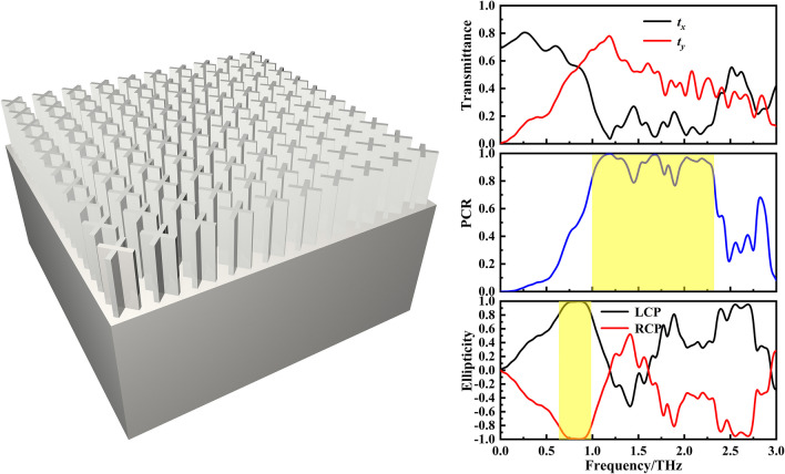
Polarization, a fundamental behavior of electromagnetic waves, holds immense potential across diverse domains such as environmental monitoring, biomedicine, and ocean exploration. However, achieving efficient modulation of terahertz waves with wide operational bandwidth poses significant challenges. Here, we introduce an all-silicon polarization converter designed specifically to operate in the terahertz range of the electromagnetic spectrum. Simulation results demonstrate that the average conversion efficiency of cross-linear waves exceeds 80% across a wide frequency range spanning from 1.00 to 2.32 THz, with the highest conversion efficiency peaking at an impressive 99.97%. Additionally, our proposed structure facilitates linear-to-circular polarization conversion with an ellipticity of 1 at 0.85 THz. Furthermore, by rotating the cross-shaped microstructure, active control over arbitrary polarization states can be achieved. To summarize, the proposed structure offers remarkable flexibility and ease of integration, providing a reliable and practical solution for achieving broadband and efficient polarization conversion of terahertz waves.
Graphical abstract
Keywords: Broadband, High efficiency, Polarization conversion, All-silicon
Introduction
With the significant advancements in terahertz (THz) science and technology, terahertz waves have become indispensable in radar [1], communication [2, 3], and imaging [4, 5]. These applications demand highly efficient optical devices, including lenses, wave plates, switches, and polarization rotators. Among these devices, polarization converters are crucial for controlling polarization and are typically constructed using optical gratings [6], birefringent crystals [7, 8] or anisotropic materials. However, traditional converters suffer from drawbacks such as large size, susceptibility to damage, and integration challenges [9, 10]. Moreover, the conventional natural materials chosen for traditional converters have significant limitations in electromagnetic response. Consequently, researchers are considering the use of metamaterials as substitutes for traditional materials.
Metamaterials [11, 12], as artificial composite materials, have gained substantial attention due to their unique electromagnetic properties, offering alternative possibilities for controlling the polarization of terahertz waves [13–17]. In 2018, Sun et al. demonstrated a transmissive metal polarization rotator with a double-layer structure, which, relative to pre-existing technologies, exhibited reduced loss and improved polarization conversion performance [18]. Cheng et al. further utilized chiral metamaterials to design a versatile terahertz polarization converter, achieving linear-to-circular polarization conversion at 1.14 and 1.34 THz, as well as cross-linear polarization conversion between 2.19 and 2.47 THz [19]. In 2020, Zi et al. proposed a transmissive dual-function terahertz wave plate based on all-dielectric metamaterials, enabling two different polarization conversions at 1.01 THz [20]. These designs operate in the transmissive mode, thereby to some extent avoiding the associated drawbacks of traditional converters and facilitating easy integration. However, their effective working bandwidth remains relatively narrow. Therefore, achieving a transmissive broadband device with high polarization conversion efficiency is important for development of control of the polarization state of terahertz waves.
In this paper, we present a broadband all-silicon transmissive multi-functional polarization converter with high efficiency, employing cross-shaped microstructures. This design enhances the effective electromagnetic response, thereby improving the device efficiency. In comparison to previously reported converters with limited working bandwidth, our proposed design offers a significantly broader operational range. Numerical simulations confirm the device’s capability to achieve polarization conversion for both cross-linear and linear-to-circular polarized waves in the terahertz frequency range. The proposed device holds potential applications in terahertz spectroscopy, imaging, and communications.
Theoretical model
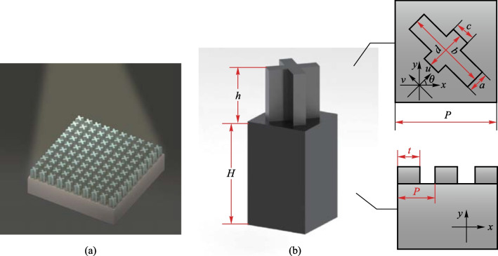
The unit cell of this polarization convertor is composed of a cross-shaped patch on top of a dielectric substrate (schematic in Fig. 1b). When a beam of terahertz waves passes through this device, its polarization direction will change. Here, is the incident polarized wave amplitude, Eix is incident wave amplitude, k is the wave number, and Eix represents the amplitude of the incident wave along the x-axis [21]. Then the transmitted wave can be expressed
| 1 |
where Etx and φx represent the amplitude and additional phase of the transmitted wave, respectively.
Fig. 1.
Schematic diagram of the designed cross-shaped microstructure. a Schematic of proposed convertor. b Stereograph of microstructure. Here, h represents height; H is substrate thickness; a–d show length and width; P is period; θ is the included angle between the cross-shaped secondary axis and the x-axis; t is the length of high-resistance silicon
If the cross-shaped microstructure in u-v coordination rotates through angle θ (θ is the included angle between the cross-shaped minor axis and the x-axis, as shown in Fig. 1b), the incident and transmitted wave amplitude in the x-direction can be expressed as [22]
| 2 |
| 3 |
The cross-shaped microstructure does not change θ, so for simplicity we usually consider that: φx = φu and φy = φv. The transmitted waves are then given by
| 4 |
Then the polarization state of transmitted waves is related to the rotated angle and the phase difference between the two orthogonal coordinate axes. The linear polarization direction of transmitted wave will rotate π/2 as long as the two polarization components along the x- and y-axis produce a phase difference of π [23],
| 5 |
where λ is the wavelength of incident wave, nu and nv are the refractive indices in u- and v-directions, respectively, and h is the thickness of cross-shaped microstructure. Since , the modulation of polarization state is related to permittivity [24], which is a unique and significant characteristic of metamaterials. We can handle the polarization direction through artificially changing the shape, size and distribution of the unit cell [25, 26]. It can be seen from Fig. 1b that the high-resistance silicon and air are arranged periodically. Therefore, the effective permittivity calculation formulas in the u-direction and v-direction can be expressed as
| 6 |
where ε1 and ε2 are the permittivities of high-resistance silicon and air, respectively, εeff is the effective permittivity, and f is the duty cycle of high resistance silicon. By appropriately adjusting the proportion of the high-resistance silicon and changing the refractive index of the convertor, the polarization direction of terahertz waves can be deflected toward the target angle.
From Eq. (4), the transmitted waves of x- and y-polarized components are also related to the rotated angle θ. When Δφ = φy − φx = π, the transmitted wave amplitudes are . Therefore, when θ = 45°, the x-polarized incident waves can be completely turned into y-polarized waves. According to Eq. (4), we set θ = 45° and the polarization direction of incident waves is then along the x-axis. The transmittance in x- and y-polarized directions are tx = Ex/Ei, ty = Ey/Ei. The polarization conversion rate (PCR) is defined as PCR = |ty|2/(|tx|2 + |ty|2). Here, Ex and Ey represent the output electrical field intensity of the terahertz waves polarized along x- and y-axis, respectively, Ei represents the electrical field intensity of incident terahertz waves.
To verify the design, the simulation is carried out in CST MWS, where the material is high-resistance silicon with ε = 11.9 and μ = 1.0. In the simulation, the periodic boundary condition in the x–y plane is applied to simulate the periodic array state. Meanwhile, the open condition along the z-direction is set to match the practical incident and transmitted terahertz wave paths. For the light source setup, we use a linearly polarized wave along the x-direction incident along the − z-axis to the metamaterial.
Results and discussion
Influence of parameters on device performance
There are several factors that affect the device performance: length, width, height, period, and substrate thickness. By varying these factors, we can obtain the influence of structural parameters on PCR, and the optimal structural parameters.
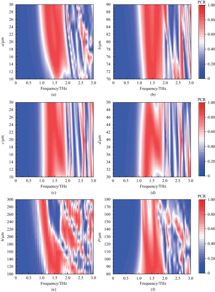
Table 1 shows the parameter scanning range of the cross-shaped microstructure. Through the parameter scanning, the optimal solution of PCR and the effective working bandwidth are obtained.
Table 1.
Scanning range of cross-shaped microstructure parameters
| Structural parameters (see Fig. 1) | Parameter scanning range/μm | Optimal value/μm |
|---|---|---|
| a | 10–30 | 30 |
| b | 70–90 | 80 |
| c | 10–30 | 30 |
| d | 30–50 | 40 |
| P | 80–180 | 80 |
| h | 100–300 | 180 |
Figure 2 illustrates the simulated PCR distributions for various structural parameters. (Here, the red area indicates that the device has high polarization conversion efficiency in this frequency band). The red areas represent PCR ≥ 80%. These area are concentrated on the range of 1.00–2.5 THz. Figure 2a–e show the impact of the cross-shaped parameters on the effective working bandwidth and PCR. When a = 30 μm, c = 30 μm, the device performance is the best. Figure 2b, d, e indicate that the effective working bandwidth increases first and then drops off, with the maximum at b = 80 μm, d = 40 μm, h = 180 μm. As shown in Fig. 2f, the period has great influence on device efficiency. With the period increasing, the effective working frequency range continuously reduces, and reaches the best value at P = 80 μm. By analyzing the influence of microstructure parameters on the polarization conversion, the optimum parameter combination of the cross-shaped microstructure is as follows: a = 30 μm; b = 80 μm; c = 30 μm; d = 40 μm; h = 180 μm; P = 80 μm.
Fig. 2.
Parameter scanning results of the microstructure. Here, the initial parameters are a = 10 μm, b = 70 μm, c = 10 μm, d = 30 μm, h = 150 μm, P = 100 μm. a–e Show the influence of the cross-shaped structure parameters on PCR, respectively. f shows the influence of the period of the microstructure on PCR
Function of broadband half-wave plate
According to the optimal structural parameters obtained by parameter scanning, the microstructure is then simulated. Figure 3 shows the transmittance and corresponding PCR of the device at the optimal parameters as determined by simulation. It can be understood that in the frequency range of 1.00–2.32 THz, PCR is greater than 80%, representing a very broad effective working bandwidth. In addition, Table 2 gives the performance of the proposed structure in comparsion with previous works. Compared with previously reported designs, our design for cross-polarization conversion has simple structure, wide operating bandwidth, and works well at wide incidence angles.
Fig. 3.
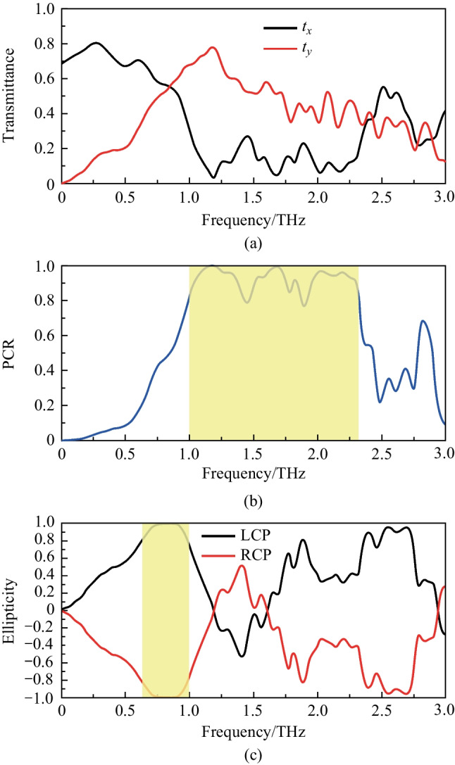
Simulation results of the polarization convertor. a Transmittance and b PCR of the cross shaped microstructure at the optimal parameters. The yellow area represents PCR exceeding 80% in this frequency range. c Performance of the device as a quarter wave plate at different incident polarized waves. The yellow area represents χ ≥ 80%. Here, a = 30 μm; b = 80 μm; c = 30 μm; d = 40 μm; h = 180 μm; P = 80 μm; H = 500 μm
Table 2.
Performance comparsion of the proposed struture with previous works
| References | Structure configuration | Operating mode | Method | Effective bandwidth/THz |
|---|---|---|---|---|
| [27] | Full dielectric elliptic column | Transmissive | The polarization conversion based on spatially staggered anisotropic birefringence effect | 0.4 (PCR ≥ 70%) |
| [28] | Three-layer metal structure | Transmissive | The polarization conversion based on wavefront manipulation | 0.6 (PCR ≥ 90%) |
| [29] | multilayer metamaterial | Transmissive | The polarization conversion of peak resonances based on GST225 material | 0.72 (PCR ≥ 70%) |
| [30] | Metal ring + multilayer film | Reflective | The polarization conversion based on VO2 phase transition properties | 0.58 (PCR ≥ 90%) |
| [31] | Z-shaped metal antennas + rods | Transmissive | The polarization conversion based on multiple interference models | 0.32 (PCR ≥ 80%) |
| This work | Cross-shaped pillars | Transmissive | The polarization conversion based on all dielectric metamaterial | 1.32 (PCR ≥ 80%) |
Function as a quarter-wave plate
In addition, this device can be used not only as a half-wave plate, but also as a quarter-wave plate. The quarter wave plate can convert linearly polarized waves into circularly or elliptically polarized waves. The expression of the quarter-wave plate can be expressed as
| 8 |
When the two orthogonal components of the transmitted waves are equal, the linearly polarized waves can be converted into circularly polarized waves. The Stokes formula describing ellipticity, χ = S1/S2, where S1 and S2 are the Stokes parameters, is used to evaluate the circular polarization effect. Here, S1 = 2|tx||ty|sinφ, S2 =|tx|2 + |ty|2, and φ is the phase difference. From Fig. 4, when the x-polarized incident waves impinge on the device, the transmitted waves are completely converted into left-handed circularly polarized waves in 0.85 THz.
Fig. 4.
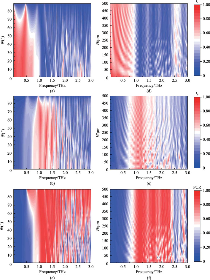
a–c Transmittance and PCR at different incident angles of the designed structure. Here, a and b represent the influence of different incident angles on the transmittance of terahertz waves in the x- and y-direction. c Represents the influence of different incident angles on PCR. d–f Transmittance and PCR at different substrate thicknesses. d, e represent transmittance of the x- and y-direction at different thicknesses. f represents PCR at different thicknesses. Here, the wider the red zone is, the better the device perform
In Fig. 4, a y-polarized wave is incident into the device, then it will be converted into right-handed circularly polarized wave at 0.85 THz. Additionally, we use PB (Pancharatnam-Berry) phase [32, 33] to change the polarization state of transmitted waves. By adjusting the spatial transformation of this device, it can also achieve a relatively effective modulation effect.
We also consider the angular dependence of the proposed polarization convertor. (The substrate thickness is set to 10 μm here). The numerically resolved transmittance and PCR are depicted in Fig. 4. As shown in Fig. 4a, b, the transmittance decreases with the increase of incident angle. While the polarization conversion performance (PCR) is minimally affected (Fig. 5c). These results show that the structure has good robustness, which is of great significance for practical applications.
Fig. 5.
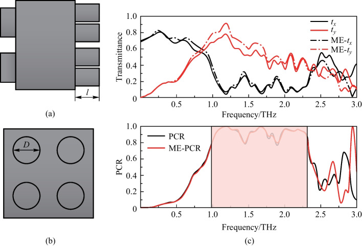
a, b Represents the microstructure with ME structure. l: height; D: diameter. c Influence of ME structure on transmittance and PCR, where solid line represents the device without ME structure, and dashed line represents adding ME structure. The red zone represents PCR exceeding 80%
Regarding the application situation of the proposed convertor, the influence of substrate thickness on device performance is analyzed. As shown in Fig. 4d–f, the red ranges represent that the transmittance and PCR are better than white areas. The redder the area, the higher the transmittance and PCR. Thus, the device is more easily integrated by reducing the thickness of substrate.
Optimization of polarization convertor
As shown in Fig. 5a–c, the incident angle seriously affects transmittance in x- and y-directions. With the angle increases, the transmittance decreases, which means that a lot of energy is lost in transmission. Therefore, it’s important to improve the energy efficiency of the device. We plate an anti-reflection film on the surface of the device to increase the transmittance [33]. Since the device adopts a metamaterial structure, the coating method is not applicable. A “moth-eye” (ME) structure is proposed to improve transmittance [34–36]. The ME structure is a periodic and regular arrangement of protrusions, as shown in Fig. 5a–b. It is always added at the bottom of the microstructure. Due to the protrusions on the surface, the reflected radiation is reduced, that is, the reflectivity is diminished and the transmittance is enhanced. Figure 5c shows the effect of the device on transmittance of terahertz waves after adding the ME structure. The ME structure with height l = 25 μm and diameter D = 35 μm have good influence on the performance of the device.
Conclusion
We present a new all-silicon metamaterial featuring a cross-shaped microstructure capable of simultaneously achieving cross-linear and linear-to-circular polarization conversion in the terahertz frequency range. By analyzing the scanning results, we determine the optimal structural parameters. Our device achieves a broadband conversion range of approximately 1.32 THz and demonstrates high efficiency, reaching up to 80% for orthogonal linear polarization conversion. Furthermore, we investigate the device’s response at various incident angles and find that it exhibits no angular dependence. Additionally, we observe that the thickness of the substrate has minimal impact on the device’s performance, confirming its excellent integration potential. To further enhance the transmittance of terahertz waves, we incorporate a magneto-electric (ME) structure. Overall, our device serves as a valuable reference for the design and theoretical analysis of transmissive broadband polarization converters, particularly in integrated terahertz systems.
Acknowledgements
The authors acknowledge the financial support from the National Key Research and Development Program of China (No. 2022YFA1203502) and the National Natural Science Foundation of China (Grant No. U2230114).
Biographies
Xiaohua Xing
is currently working toward the Ph.D. degree in Optoelectronic and Photonics Technology with the Department of Precision Instrument and Opto-Electronic Engineering, Tianjin University, Tianjin, China. He obtained his B.Sc. and Master degrees in in the School of Precision Instruments and Optoelectronics Engineering, Tianjin University. His research interests include terahertz, metamaterials, and artificial intelligence.
Die Zou
is currently working toward the Ph.D. degree in Optoelectronic and Photonics Technology with the Department of Precision Instrument and Opto-Electronic Engineering, Tianjin University, Tianjin, China. She received the B.S. degree in the School of Physical Science and Technology from Tianjin Polytechnic University, Tianjin, China, in 2019. Her research interests include terahertz, metamaterials, and bound state in the continuum (BIC).
Xin Ding
obtained his doctorate in the School of Precision Instruments and Opto Electronics Engineering, Tianjin University, Tianjin, China. His research interests are solid-state laser, tunable laser, nonlinear optical frequency transformation.
Jianquan Yao
obtained his B.Sc. and Master degrees in in the School of Precision Instruments and Opto Electronics Engineering, Tianjin University, Tianjin, China. His research interests are terahertz, metamaterials, nonlinear frequency-inversion laser.
Liang Wu
obtained his B.Sc. and Ph.D. degrees in Optical Engineering from Wuhan National Laboratory for Optoelectronics, Huazhong University of Science and Technology, Wuhan, China. Now he is an associate professor in Tianjin University, Tianjin, China, and teaches College Physics and Solid-State Physics. His research interests are terahertz, metamaterials, AI for science and topological photonics.
Author contribution
XX and DZ carried out the design and simulation studies of the polarization conversion structure and drafted the manuscript. XD and JY supervised this study. LW reviewed and edited the manuscript.
Availability of data and materials
The data that support the findings of this study are available from the corresponding author, upon reasonable request.
Declarations
Competing interests
The authors declare no competing interests.
Footnotes
Xiaohua Xing and Die Zou contributed equally to this work.
References
- 1.Nie XY, Zhang YL, Xiang FD, Lu JG, Huang X, Wang KJ, Liu JS, Yang ZG. Cross section measurements of scale-model tactical targets by using 0.1 THz compact radar system. Chin. Opt. Lett. 2017;15:112201. doi: 10.3788/COL201715.112201. [DOI] [Google Scholar]
- 2.Xiao ZY, Yang QJ, Huang JG, Huang ZM, Zhou W, Gao YQ, Shu R, He ZP. Terahertz communication windows and their point-to-point transmission verification. Appl. Opt. 2018;57:7673–7680. doi: 10.1364/AO.57.007673. [DOI] [PubMed] [Google Scholar]
- 3.Seeds AJ, Shams H, Fice MJ, Renaud CC. Terahertz photonics for wireless communications. J. Lightwave Technol. 2015;33:579–587. doi: 10.1109/JLT.2014.2355137. [DOI] [Google Scholar]
- 4.Funaki C, Toyouchi T, Hoshina H, Ozaki Y, Sato H. Terahertz imaging of the distribution of crystallinity and crystalline orientation in a poly(ɛ-caprolactone) film. Appl. Spectrosc.Spectrosc. 2017;71:1537–1542. doi: 10.1177/0003702816684838. [DOI] [PubMed] [Google Scholar]
- 5.Guerboukha H, Nallappan K, Skorobogatiy M. Toward real-time terahertz imaging. Adv. Opt. Photon. 2018;10:843–938. doi: 10.1364/AOP.10.000843. [DOI] [Google Scholar]
- 6.Caucheteur C, Guo T, Albert J. Polarization-assisted fiber Bragg grating sensors: tutorial and review. J. Lightwave Technol. 2017;35:3311–3322. doi: 10.1109/JLT.2016.2585738. [DOI] [Google Scholar]
- 7.Haigh JA, Kinebas Y, Ramsay AJ. Inverse conoscopy: a method to measure polarization using patterns generated by a single birefringent crystal. Appl. Opt. 2014;53:184–188. doi: 10.1364/AO.53.000184. [DOI] [PubMed] [Google Scholar]
- 8.Przhiyalkovskiy YV, Starostin NI, Morshnev SK, Sazonov AI. Polarization dynamics of light propagating in bent spun birefringent fiber. J. Lightwave Technol. 2020;38:6879–6885. doi: 10.1109/JLT.2020.3017795. [DOI] [Google Scholar]
- 9.Masson JB, Gallot G. Terahertz achromatic quarter-wave plate. Opt. Lett. 2006;31:265–267. doi: 10.1364/OL.31.000265. [DOI] [PubMed] [Google Scholar]
- 10.Kaveev AK, Kropotov GI, Tsygankova EV, Tzibizov IA, Ganichev SD, Danilov SN, Olbrich P, Zoth C, Kaveeva EG, Zhdanov AI, Ivanov AA, Deyanov RZ, Redlich B. Terahertz polarization conversion with quartz waveplate sets. Appl. Opt. 2013;52:B60–B69. doi: 10.1364/AO.52.000B60. [DOI] [PubMed] [Google Scholar]
- 11.Zhilin AA, Tagantsev DK, Alemaskin MY, Shepilov MP, Zapalova SS, Sazonov ME. Metamaterials with a network structure. J. Opt. Technol. 2012;79:241–245. doi: 10.1364/JOT.79.000241. [DOI] [Google Scholar]
- 12.Wang J, Wang S, Singh RJ, Zhang WL. Metamaterial inspired terahertz devices: from ultra-sensitive sensing to near field manipulation. Chin. Opt. Lett. 2013;11:011602. doi: 10.3788/COL201311.011602. [DOI] [Google Scholar]
- 13.Cheng YZ, Zhu XZ, Li J, Chen F, Luo H, Wu L. Terahertz broadband tunable reflective cross-polarization convertor based on complementary cross-shaped graphene metasurface. Phys E Low Dimens. Syst. 2021;134:114993. [Google Scholar]
- 14.Zhu, X. Z., Cheng, Y. Z., Fan, J. P., Chen, F., Luo, H., Wu, L.: Switchable efficiency terahertz anomalous refraction and focusing based on graphene metasurface. Diamond Relat Mater. 121,108743 (2022)
- 15.Cheng Y, Yu J, Li X. Tri-band high-efficiency circular polarization convertor based on double-split-ring resonator structures. Appl. Phys. B. 2022;128:1. doi: 10.1007/s00340-021-07724-4. [DOI] [Google Scholar]
- 16.Zhao J, Li N, Cheng Y. All-dielectric InSb metasurface for broadband and high-efficient thermal tunable terahertz reflective linear-polarization conversion. Opt. Commun.Commun. 2023;536:129372. doi: 10.1016/j.optcom.2023.129372. [DOI] [Google Scholar]
- 17.Li N, Zhao JC, Tang PY, Cheng YZ. Design of all-metal 3D anisotropic metamaterial for ultrabroadband terahertz reflective linear polarization conversion. Phys Status Solidi B Basic Res. 2023;260:2300104. doi: 10.1002/pssb.202300104. [DOI] [Google Scholar]
- 18.Sun H, Zhang YX, Wang KL, Zhao YC, Kou W, Liang SX, Han JG, Yang ZQ. Linear polarization conversion of transmitted terahertz wave with double-layer meta-grating surfaces. Chin. Opt. Lett. 2018;16:081601. doi: 10.3788/COL201816.081601. [DOI] [Google Scholar]
- 19.Cheng ZZ, Cheng YZ. A multi-functional polarization convertor based on chiral metamaterial for terahertz waves. Opt. Commun.Commun. 2019;435:178–182. doi: 10.1016/j.optcom.2018.11.038. [DOI] [Google Scholar]
- 20.Zi JC, Ji YF, Xi F, Xu Q, Liu HC, Zhang XX, Han JG, Zhang WL. Dual-functional terahertz waveplate based on all-dielectric metamaterial. Phys. Rev. Appl. 2020;13:034042. doi: 10.1103/PhysRevApplied.13.034042. [DOI] [Google Scholar]
- 21.Kumar A, Ghatak A. Polarization of light with applications in optical fibers. Bellingham, WA, USA: SPIE Press; 2011. [Google Scholar]
- 22.Zi J, Xu Q, Wang Q, Tian C, Li Y, Zhang X, Han J, Zhang W. Terahertz polarization converter based on all-dielectric high birefringence metamaterial with elliptical air holes. Opt. Commun.Commun. 2018;416:130–136. doi: 10.1016/j.optcom.2018.02.012. [DOI] [Google Scholar]
- 23.Maxwell JC. A treatise on electricity and magnetism. UK: Clarendon Press; 1873. [Google Scholar]
- 24.Born M, Wolf E. Principles of optics. London: Cambridge University Press; 1999. [Google Scholar]
- 25.Veselago VG. The electrodynamics of substances with simultaneously negative values of ε and µ. Soviet Physics Uspekhi. 1968;10:509. doi: 10.1070/PU1968v010n04ABEH003699. [DOI] [Google Scholar]
- 26.Fu X, Cui TJ. Recent progress on metamaterials: from effective medium model to real-time information processing system. Prog. Quantum Electron. 2019;67:100223. doi: 10.1016/j.pquantelec.2019.05.001. [DOI] [Google Scholar]
- 27.Li J, Zheng CL, Li JT, et al. Terahertz wavefront shaping with multi-channel polarization conversion based on all-dielectric metasurface. Photonics Res. 2021;9:1939–1947. doi: 10.1364/PRJ.431019. [DOI] [Google Scholar]
- 28.Yan W, Shaohe L, Hui W, et al. Broadband and efficient asymmetric wavefront manipulation via terahertz polarization-selective metasurface. Appl. Phys. Lett. 2022;121:151701. doi: 10.1063/5.0101731. [DOI] [Google Scholar]
- 29.Meng L, Ying S, Kuan L, et al. Nonvolatile switchable broadband polarization conversion with wearable terahertz chalcogenide metamaterials. Adv. Opt. Mater. 2023;11:2202439. doi: 10.1002/adom.202202439. [DOI] [Google Scholar]
- 30.Peng Z, Zheng Z, Yu Z, et al. Broadband absorption and polarization conversion switchable terahertz metamaterial device based on vanadium dioxide. Opt. Laser Technol. 2023;157:108723. doi: 10.1016/j.optlastec.2022.108723. [DOI] [Google Scholar]
- 31.Tao X, Qi L, Yang J, et al. Bifunctional terahertz metasurface for transmissive broadband linear-to-circular and linear polarization conversion. IEEE T THz Sci. Techn. 2023;13:254–261. doi: 10.1109/TTHZ.2023.3250943. [DOI] [Google Scholar]
- 32.Gutiérrez-Vega JC. Pancharatnam-Berry phase of optical systems. Opt. Lett. 2011;36:1143–1145. doi: 10.1364/OL.36.001143. [DOI] [PubMed] [Google Scholar]
- 33.Tian Y, Jing XF, Yu H, Gan HY, Li CX, Hong Z. Manipulation of the arbitrary scattering angle based on all-dielectric transmissive Pancharatnam Berry phase coding metasurfaces in the visible range. Opt. Express. 2020;28:32107–32123. doi: 10.1364/OE.409509. [DOI] [PubMed] [Google Scholar]
- 34.Zi J, Xu Q, Wang Q, Tian C, Li Y, Zhang X, Han J, Zhang W. Antireflection-assisted all-dielectric terahertz metamaterial polarization converter. Appl. Phys. Lett. 2018;113:101104. doi: 10.1063/1.5042784. [DOI] [Google Scholar]
- 35.Sakurai H, Nemoto N, Konishi K, Takaku R, Sakurai Y, Katayama N, Matsumura T, Yumoto J, Kuwata-Gonokami M. Terahertz broadband anti-reflection moth-eye structures fabricated by femtosecond laser processing. OSA Continuum. 2019;2:2764–2772. doi: 10.1364/OSAC.2.002764. [DOI] [Google Scholar]
- 36.Tan GJ, Lee J, Lan YH, Wei MK, Peng LH, Cheng IC, Wu ST. Broadband antireflection film with moth-eye-like structure for flexible display applications. Optica. 2017;4:678–683. doi: 10.1364/OPTICA.4.000678. [DOI] [Google Scholar]
Associated Data
This section collects any data citations, data availability statements, or supplementary materials included in this article.
Data Availability Statement
The data that support the findings of this study are available from the corresponding author, upon reasonable request.


