Abstract
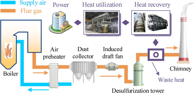
The saturated flue gas is difficult to recover and use as low-grade waste heat in a coal-fired power plant. The absorption heat pump is important equipment for recovering low-grade waste heat. In this article, the saturated flue gas waste heat is recovered to reduce the turbine extraction steam of low-pressure heaters. The simulation system is built, and the operational characteristics are analyzed. The feasibility of saturated flue gas waste heat recovered is verified by the absorption heat pump to heat the boiler feedwater. The results show that generator pressure and throttle pressure have significant influence on the operational performance of the absorption heat pump. There is the risk of solution crystallization with the high-concentration dehumidification solution. The equivalent enthalpy drop of the extraction steam is lower in the higher number of heater stages, representing the weaker electricity generation capacity. The waste heat temperature of saturated flue gas can be raised by 30–40 °C, which is used as the low-grade heat source for the absorption heat pump. The feedwater of low-pressure heaters is heated by the absorption heat pump, and its temperature ranges from 59.2 to 83.8 °C. The simulation system can efficiently recover the waste heat of saturated flue gas up to 9.99 MW and achieve additional electricity generation up to 0.56 MW in the coal-fired power plant.
1. Introduction
The coal is an important fossil energy source in China. It is significant to carry out research on energy saving and consumption reduction1,2 in the coal-fired power plants. At present, there are two main aspects of waste heat loss in the coal-fired power plants, respectively, for the waste heat of turbine exhaust steam3 and the waste heat of saturated flue gas.4 The former is the waste heat loss caused by condensation of turbine exhaust steam.5 The latter is the waste heat loss caused by the saturated flue gas exhaust through the chimney.6 The flue gas is scrubbed and purified by the wet desulfurization tower to reach the ultralow emission standard in the coal-fired power plant, and the flue gas is saturated with humidity.7,8 At the same time, the waste heat temperature of saturated flue gas is about 50–55 °C, and the waste heat temperature of turbine exhaust steam is about 30–40 °C in the condensing turbine. Compared with the turbine exhaust steam, the waste heat temperature of saturated flue gas is higher and the saturated flue gas waste heat is used in more various paths.
The waste heat of saturated flue gas is the largest heat loss in the boiler for a coal-fired power plant. In the 600 MW coal-fired power plant, the waste heat of saturated flue gas is about 58.9 MW. The saturated flue gas waste heat is mainly the latent heat of the water vapor at the desulfurization tower outlet. The literature9 aims to investigate the latent heat recovery from the saturated flue gas and built the pilot-scale testing system which the heat-transfer coefficient reached up to 275 W/(m2 K). The literature10 analyzed the heat- and mass-transfer characteristics of the spray tower, the experimental and simulation results are shown with relative agreement. The literature11 designed a heat recovery device which includes a condensing heat exchanger, spray unit, and sensible heat exchanger, and the spray unit effectively enhances the effect of the supply air being heated. The absorption heat pump is also important piece of equipment for waste heat recovery in a coal-fired power plant. The literature12 used the lithium bromide solution as the dehumidification solution, established an open absorption heat pump model to recovery flue gas waste heat, and found that the absorber and generator are critical to the system operation. The literature13 proposed the optimized absorption heat pump system with a two-stage generator, and the optimized absorption heat pump COP can be increased by 4.2%. There are also some scholars who focus on the utilization of saturated flue gas waste heat. The literature14 recovered flue gas waste heat by installing the nonphase change heat exchanger at the wet desulfurization tower inlet and preheated the combustion air by installing the phase change heat exchanger. The literature6 applied the compression heat pump in the heating system, which utilized electrical energy to heat feedwater with the return water as the low-grade heat source, and enhanced flue gas heat exchange capacity from 1.92 to 2.11 MW. At the same time, there are two types of flue gas waste heat recovery approaches for the contact and the noncontact. The direct-contact spray tower reduces the flue gas temperature by relying on the cold source medium. Compared with the traditional noncontact heat exchanger,15 the direct-contact spray tower has obvious advantages in the heat-transfer area and temperature difference.16−18 The direct-contact spray tower also helps to avoid the corrosion phenomenon of the heat-transfer material and reduce the operation cost and maintenance cost. In order to efficiently recover the waste heat of saturated flue gas, the literature19 designed a cooling tower device with an operation resistance no more than 240 Pa, and the device can recover waste heat with 24 MW in the 140 MW boiler. The literature18 also built an experiment platform, including a direct-contact spray tower to recover flue gas waste heat, and the heat recovery efficiency can reach 74.7%.
Combined with the current research, it is difficult to match the appropriate cold source media to recover the saturated flue gas waste heat. Meanwhile, the utilization pathway of the saturated flue gas waste heat is affected by the temperature level.14,24−26 The absorption heat pump can use dehumidification solutions as circulating media, which have strong hygroscopic properties,20−22 and provide the stable cold source medium to recover flue gas waste heat. This paper proposes a saturated flue gas waste heat recovery system including an absorption heat pump and a direct-contact spray tower. Based on the direct-contact spray tower, the absorption heat pump provides a significant enhancement to recover the saturated flue gas waste heat.23 Moreover, the saturated flue gas waste heat is used to heat the boiler feedwater. The waste heat utilization process reduces the turbine extraction steam of low-pressure heaters, which continues to do work in the turbine. Taking a 350 MW coal-fired power plant as an example, this paper analyzes the operation mechanism of the absorption heat pump and investigates the flue gas temperature, the turbine extraction steam enthalpy drop, etc., which affect the operation characteristics of the flue gas waste heat recovery system. Finally, the feasibility of recovering the saturated flue gas waste heat to heat boiler feedwater is clarified, and the energy-saving theory and the application effect are revealed in this paper.
1.1. Saturated Flue Gas Waste Heat Recovery System
1.1.1. Coal-fired Power Plant
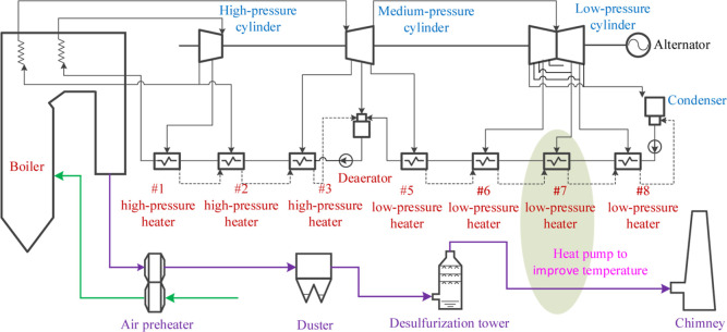
The typical 350 MW high-efficiency supercritical coal-fired power plant is selected as the research object. The flue gas discharge temperature is 125–135 °C at the air preheat outlet, and the flue gas flow is 1,338,000 N m3/h. The flue gas temperature is reduced to 50–55 °C by the wet desulfurization tower. Meanwhile, the extraction condensing turbine is used in the coal-fired power plant, which is produced by the Harbin Turbine Plant. As shown in Figure 1, the turbine is composed with a high-pressure cylinder, medium-pressure cylinder, and low-pressure cylinder. Moreover, there are 8 sections of return heat extraction arranged in the regeneration heat system. In addition, the flue gas is discharged into the atmosphere after a wet desulfurization tower by the chimney. In this paper, the saturated flue gas waste heat recovery system is built, which integrates the flue gas discharge system and the turbine regeneration heat system. The absorption heat pump is used to increase the temperature of the saturated flue gas waste heat. In addition, the flue gas waste heat is used to heat the feedwater of the low-pressure heater and reduce the extraction steam of low-pressure heaters, which returned to the turbine to increase the electricity generation capacity of the coal-fired power plant.
Figure 1.
Coal-fired power plant flue gas discharge and the regeneration heat system.
In the 350 MW coal-fired power plant, the temperature of new steam is 600 °C, the flow of new steam is 967.7 t/h, and the enthalpy of new steam is 3501.1 kJ/kg. Moreover, the temperature of the reheat steam is 600 °C, the flow of the reheat steam is 794.3 t/h, and the enthalpy of the reheat steam is 3668.6 kJ/kg. The temperature of exhaust steam at the low-pressure cylinder outlet is 33 °C, the flow of exhaust steam is 546.7 t/h, and the enthalpy of exhaust steam is 2362.2 kJ/kg. The parameters of extraction steam in the regeneration heat system are shown in Table 1. As the heater serial number increases, the extraction steam pressure decreases gradually, and the temperature and the enthalpy of extraction steam show the same change pattern.
Table 1. Extraction Steam Parameters of a Regeneration Heat System in the 350 MW Coal-fired Power Planta.
| heater serial number | temperature of extraction steam (°C) | flow of extraction steam (t/h) | pressure of extraction steam (MPa) | enthalpy of extraction steam (kJ/kg) | enthalpy of condensation water (kJ/kg) |
|---|---|---|---|---|---|
| #1 H.P. | 406.9 | 57.31 | 7.364 | 3170.6 | 1184.9 |
| #2 H.P. | 360.1 | 94.02 | 5.194 | 3091.4 | 948.8 |
| #3 H.P. | 476.9 | 48.75 | 2.195 | 3414.8 | 802.2 |
| deaerator | 365.3 | 19.87 | 1.007 | 3190.4 | 754.4 |
| #5 L.P. | 274.7 | 37.37 | 0.492 | 3012.5 | 512.5 |
| #6 L.P. | 183.2 | 38.68 | 0.205 | 2836.7 | 374.3 |
| #7 L.P. | 87.9 | 28.45 | 0.065 | 2638 | 271 |
| #8 L.P. | 63.1 | 24.5 | 0.023 | 2495.3 | 167.1 |
Note: L.P. means low-pressure heater, and H.P. means high-pressure heater.
1.1.2. Building the System Model
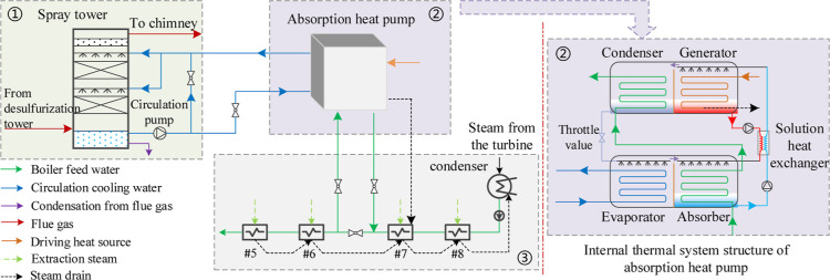
As shown in Figure 2, the saturated flue gas waste heat recovery system can be divided into three parts, including the waste heat recovery part, the waste heat raising part, and the waste heat utilization part. The direct-contact spray tower is the main equipment in the waste heat recovery part. The flue gas flows from the bottom to the top in the spray tower, and the circulation cooling water spray from the top to the bottom through the multilayer nozzle. The saturated flue gas flows in the opposite direction to the circulation cooling water, and the part of the saturated flues gas waste heat is transferred to the circulation cooling water through direct contact in the spray tower. The absorption heat pump is also the main equipment in the waste heat quality part. The absorption heat pump adopts the lithium bromide solution as the dehumidification solution.27,28 The main components of the absorption heat pump are the generator, condenser, evaporator, throttle, and absorber. The absorption heat pump utilizes the small amount of high-grade heat to produce the large amount of medium-grade heat with circulation cooling water as the low-grade heat source. The waste heat utilization part connects #7 low-pressure heater, absorption heat pump, and #6 low-pressure heater in series. Moreover, the boiler feedwater is initially heated by the steam drain in the #7 low-pressure heater and then enters into the #6 low-pressure heater after passing through the absorber and condenser in the absorption heat pump in turn. Meanwhile, the steam drain of the driving heat source from the absorption heat pump is sent to the #7 low-pressure heater, which is combined with the steam drain of the #5 low-pressure heater and #6 low-pressure heater.
Figure 2.
Saturated flue gas waste heat recovery system.
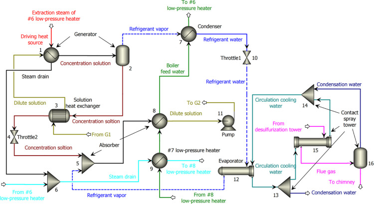
As shown in Figure 3, the Aspen Plus is used to construct the simulation model of the saturated flue gas waste heat recovery system.29,30 The simulation flow medium includes lithium bromide solution, water, and flue gas in the model. As shown in the following Table 2, the generator in the absorption heat pump is replaced by the heater and flash modules, the condenser in the absorption heat pump is replaced by a condenser module, the throttle in the absorption heat pump is replaced by throttle1 module, the evaporator in the absorption heat pump is replaced by the HeatX module, and the absorber in the absorption heat pump is replaced by mixer and heater modules. The #7 low-pressure heater is replaced by the heater module, and the direct-contract spray tower is replaced by mixer, FSplit, HeatX, and flash modules.
Figure 3.
Simulation system of saturated flue gas waste heat recovery.
Table 2. Critical Components in the Saturated Flue Gas Waste Heat Recovery System.
| system components | module types | module number | imported flow units | export flow units | |
|---|---|---|---|---|---|
| absorption heat pump | generator | heater + Flash2 | 1 + 2 | dilute solution turbine extraction steam | steam drain concentrated solution refrigerant vapor |
| absorption heat pump | condenser | heater | 7 | boiler feedwater refrigerant vapor | refrigerant fluid boiler feedwater |
| absorption heat pump | evaporator | HeatX | 12 | refrigerant fluid circulation cooling water | circulation cooling water refrigerant vapor |
| absorption heat pump | absorber | mixer + heater | 5 + 8 | refrigerant vapor concentrated solution boiler feedwater | dilute solution boiler feedwater |
| absorption heat pump | throttle | throttle1 | 10 | refrigerant fluid | refrigerant fluid |
| absorption heat pump | solution heat exchanger | HeatX | 3 | dilute solution concentrated solution | dilute solution concentrated solution |
| #7 low-pressure heater | heater | 9 | boiler feedwater steam drain | boiler feedwater steam drain | |
| spray tower | FSplit + mixer + HeatX + Flash2 | 13 + 14 + 15 + 16 | flue gas circulation cooling water | flue gas circulation cooling water condensation | |
2. Theoretical Analysis
2.1. Energy Flow Analysis
Figure 4 shows the saturated flue gas waste heat recovery model in a coal-fired power plant. The boiler feedwater has been heated to 288.8 °C from 34.3 °C by the extraction steam. The absorption heat pump is used to recover the saturated flue gas waste heat at the wet desulfurization tower outlet and produce a large amount of medium-grade heat to heat the feedwater of #7 low-pressure heater. Meanwhile, the absorption heat pump consumes the small amount of high-grade extraction steam as the driving heat source. As a result, the output heat is the sum of the driving heat and the flue gas waste heat in the absorption heat pump, and the temperature of output heat is higher than the waste heat temperature of saturated flue gas. The output heat of absorption heat pump can reduce extraction steam of #7 low-pressure heater, which returns to the turbine and increases electricity generation.
Figure 4.
Theoretical model of saturated flue gas waste heat recovery.
The absorption heat pump is the key piece of equipment in the saturated flue gas waste heat recovery system. Following the basic law of energy conservation, the sum of the driving heat source and the recovering saturated flue gas waste heat is equal to the medium-grade heat produced in the absorption heat pump.13 As shown in eq 1, the COP is used as the key indicator for evaluating operation performance of the absorption heat pump,7,31,32 and the value is the ratio of the medium-grade heat to the high-grade heat.
| 1 |
Where Q1 is the saturated flue gas waste heat recovered by the absorption heat pump, MW. Qh is the high-grade heat required in the absorption heat pump, MW. Qm is the medium-grade heat produced by the absorption heat pump, MW.
The saturated flue gas waste heat includes the latent heat of water vapor and the sensible heat of noncondensation gases.33,34 The composition percentages of flue gas waste heat are shown in eqs 2 and 3.
| 2 |
| 3 |
Where β is the percentage rate of latent heat in the saturated flue gas waste heat recovered, %. Qto is the total saturated flue gas waste heat recovered, MW. Qse is the sensible heat recovered from the saturated flue gas, MW. Qla is the latent heat recovered from the saturated flue gas, MW.
2.2. Evaluation Analysis of Turbine Extraction Steam
The enthalpy drop of the turbine extraction steam can be calculated in two ways: theoretical enthalpy drop and equivalent enthalpy drop, respectively. The theoretical enthalpy drop is the difference between the turbine extraction steam enthalpy and the turbine exhaust steam enthalpy. In addition, the equivalent enthalpy drop integrates the effect of extraction steam on the regenerative system. Therefore, it is more accurate to analyze the work capacity of the extraction steam by the equivalent enthalpy drop.35 The calculation method of the equivalent enthalpy drop is shown in eqs 4–6.
Where, there is the calculation method for equivalent enthalpy drop of extraction steam in the #8 low-pressure heater.
| 4 |
Where, there is the calculation method for an equivalent enthalpy drop of extraction steam in the #7 low-pressure heater.
| 5 |
Where, there is the calculation method for equivalent enthalpy drop of extraction steam in the #6 low-pressure heater.
 |
6 |
Where ΔHi is the equivalent enthalpy drop, kJ/kg. The subscript i is the heater serial number, for instance, 8, 7, 6, and so forth. Hc is the enthalpy of exhaust steam, kJ/kg. Hi is the turbine extraction steam enthalpy in the low-pressure heater, kJ/kg. Hji is the drain enthalpy of turbine extraction steam in the low-pressure heaters, kJ/kg.
The extraction steam efficiency means the ability of the turbine extraction steam to do work. According to the extraction steam efficiency, one can obviously distinguish the work capacity of the turbine extraction steam. The calculation formula is shown in eq 7.
| 7 |
Where ΔHi is the equivalent enthalpy drop of the turbine extraction steam, kJ/kg. qi is the heat released by the turbine extraction steam in the low-pressure heater, kJ/kg. ηi is the extraction steam efficiency.
2.3. Changing Characteristics of Electricity Generation
With the absorption heat pump to recover the saturated flue gas waste heat, the electricity generation is mainly related to the parameters of the driving heat source and the parameters of the reducing extraction steam. Taking the extraction steam of the #6 low-pressure heater as the driving heat source leads to the decrease in the amount of work steam in the turbine and reduces the electricity generation of the coal-fired power plant. At the same time, the medium-grade heat produced by the absorption heat pump reduces the turbine extraction steam and increases the electricity generation of the coal-fired power plant.36 The formulas are shown in eqs 8–10.
| 8 |
| 9 |
| 10 |
When the actuality temperature of feedwater is higher than the design temperature of feedwater at the #7 low-pressure heater outlet by the absorption heat pump, the turbine extraction steam to heat the feedwater of #6 low-pressure heater can be further reduced. Moreover at this time, the increased electricity generation is obtained in two parts, which are the extraction steam of #7 low-pressure heater and the extraction steam of #6 low-pressure heater. When the actuality temperature of feedwater is lower than the design temperature of feedwater at the #7 low-pressure heater outlet by the absorption heat pump, in order to make the actuality temperature of feedwater at the #6 low-pressure heater outlet reach the designed value, it is necessary to additionally increase the extraction steam of #6 low-pressure heater. The electricity generation is down in the coal-fired power plant. In summary, the influence characteristics of the saturated flue gas waste heat recovery to reduce the turbine extraction steam on the electricity generation can be analyzed by following eq 11.
| 11 |
Where P is the electricity generation change, MW. Pr is the electricity generation reduced by consuming the extraction steam of the #6 low-pressure heater, MW. Pa is the electricity generation increased by reducing extraction steam of the #7 low-pressure heater, MW. mw is the feedwater flow of the #6 low-pressure heater, kg/s. m7 is the extraction steam flow of the #7 low-pressure heater, kg/s. h6d is the design enthalpy value of feedwater at the #6 low-pressure heater inlet, kJ/kg. h6a is the actuality enthalpy value of feedwater at the 6 # low-pressure heater inlet, kJ/kg.
3. Results and Discussion
The saturated flue gas waste heat recovery system is constructed based on simulation software. The key node parameters are listed in Table 3. With the high-grade heat for heating the lithium bromide dilution solution in the absorption heat pump, the vapor phase fraction is 0.18 at the generator outlet, and the water vapor flow is 12.56 t/h at the condenser inlet. The circulation cooling water is used to reduce the saturated flue gas temperature by a direct-contact spray tower. Consequently, the vapor phase fraction of the saturated flue gas is changed from 1 to 0.98, and the condensation water flow from the saturated flue gas is 10.73 t/h. The feedwater temperature is 59.2 °C at the #8 low-pressure heater outlet, and it is gradually heated to 62.9, 74, and 83.9 °C through the #7 low-pressure heater, the absorber of absorption heat pump, and the condenser of absorption heat pump. Finally, the feedwater enters the #6 low-pressure heater. The boiler feedwater is heated by the absorption heat pump, which reduces the extraction steam flow of #7 low-pressure heater by 28.45 t/h. The saturated flue gas waste heat recovery system has increased the electricity generation by 0.19 MW in the coal-fired power plant.
Table 3. Operation Parameters for the Saturated Flue Gas Waste Heat Recovery System.
| |
cold
fluid medium |
hot
fluid medium |
|||||||
|---|---|---|---|---|---|---|---|---|---|
| projects | inlet/outlet temperature/°C | pressure/MPa | flow/t/h | vapor phase fraction | inlet/outlet temperature/°C | pressure/MPa | flow/t/h | vapor phase fraction | |
| the absorption heat pump | generator | 105.0/125.8 | 0.5 | 100 | 0 to 0.18 | 183.2/121.0 | 2.05 | 15.25 | 1 to 0 |
| the absorption heat pump | condenser | 74.0/83.9 | 729.2 | 1 to 0 | 125.8/78.3 | 0.5 | 12.56 | 0 | |
| the absorption heat pump | throttle | 78.3/39.3 | 0.07 | 12.56 | 0 to 0.07 | ||||
| the absorption heat pump | evaporator | 39.3/39.3 | 0.07 | 12.56 | 0 to 1 | 49/42.3 | 1 | 1010.7 | 0 |
| the absorption heat pump | absorber | 62.9/74 | 729.2 | 0 | 76/64.4 | 0.07 | 100 | 0.17 to 0 | |
| the absorption heat pump | solution heat exchanger | 64.4/105.0 | 0.5 | 100 | 0 | 125.8/76 | 0.5 | 87.4 | 0 |
| #7 low-pressure heater | 59.2/62.9 | 729.2 | 0 | 94.6/64.7 | 10 | 91.3 | 0 | ||
| direct-contact spray tower | 42.3/49 | 1010.7 | 0 | 52.0/49.6 | 956.8 | 1 to 0.98 | |||
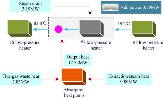
The saturated flue gas waste heat is recovered by the absorption heat pump to heat the boiler feedwater. The energy flow analysis of the thermal process in the saturated flue gas waste heat recovery system is shown in Figure 5. The energy flow of the driving heat source is 9.89 MW in the absorption heat pump, and the energy flow of the saturated flue gas waste heat recovered is 7.83 MW, and the energy flow of medium-grade heat source is 17.72 MW, which is the sum of driving heat source and the saturated flue gas waste heat recovered. At the same time, the steam drain from the #6 low-pressure heater enters the #7 low-pressure heater, and the steam drain energy flow is 3.19 MW, which is used to heat boiler feedwater. In summary, the boiler feedwater temperature is 59.2 °C at the #8 low-pressure heater outlet, and the boiler feedwater reaches the design temperature at the #6 low-pressure heater inlet, which is 83.8 °C. The electricity generation increased is 0.19 MW in the coal-fired power plant.
Figure 5.
Heat balance for the saturated flue gas waste heat recovery system.
3.1. Operational Characteristics of the Absorption Heat Pump
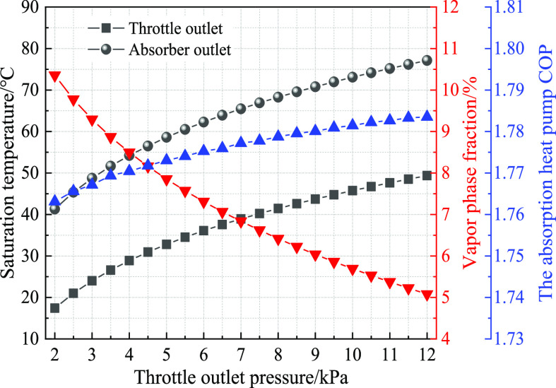
The absorption heat pump can reduce the refrigerant liquid pressure by a throttle valve. There is a small amount of refrigerant liquid evaporation after the throttle valve. Moreover, the refrigerant fluid temperature is reduced to the saturation state by the evaporation process. With refrigerant liquid entering the evaporator, the absorption heat pump can absorb heat from the low-grade heat source by the low-temperature refrigerant. Therefore, the refrigerant fluid becomes completely gas in the evaporator. As can be seen in Figure 6, with the outlet pressure of throttle valve increases, the saturation temperature of the refrigerant liquid also increases. When the outlet pressure of throttle valve increases from 2 to 12 kPa, the saturation temperature of refrigerant liquid is changed from 17.42 to 49.37 °C. At the same time, the saturated solution temperature at the absorber outlet increases with the outlet pressure of the throttle valve increases. When the outlet pressure of the throttle valve increases from 2 to 12 kPa, the saturated solution temperature at the absorber outlet is changed from 41.3 to 77.12 °C. The heat-transfer rate of the evaporator decreases along with the outlet pressure of the throttle valve increases because of increasing the saturated temperature of the refrigerant liquid. The heat-transfer rate of the absorber increases along with the outlet pressure of the throttle valve increases because of increasing the saturated temperature of lithium bromide solution. Thus, raising the outlet pressure of the throttle valve reduces the heat-transfer rate in the evaporator and increases the heat-transfer rate in the absorber. At the same time, the vapor phase fraction at the throttle valve outlet decreases by increasing the outlet pressure of the throttle valve. With the expansion of the heat absorption of the evaporator, the absorption heat pump COP rises from 1.76 to 1.78. The absorption heat pump COP is increased through increasing the outlet pressure of throttle valve and increasing the outlet pressure of throttle valve is equivalent to the low-grade flue gas waste heat with higher temperatures, which is consistent with the literature.37,38 Therefore, it is necessary to take into account the outlet pressure of the throttle valve because of the heat-transfer rate and the COP in the absorption heat pump.
Figure 6.
Effects of pressure parameters at the throttle valve outlet.
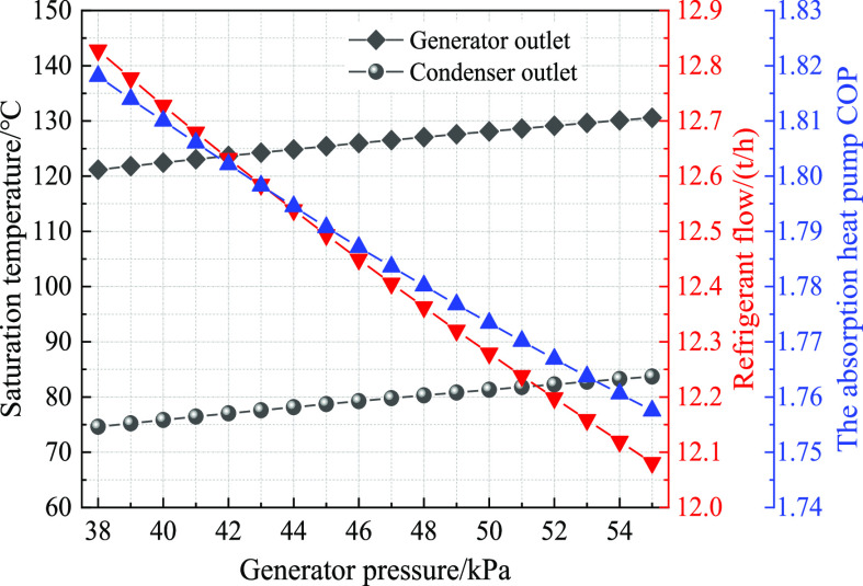
The lithium bromide dilute solution is heated by the high-grade heat source in the generator. The refrigerant vapor with a high temperature enters the condenser from the generator, which realizes the refrigerant regeneration. At the same time, the lithium bromide dilute solution is transformed into the lithium bromide concentration solution by splitting off the refrigerant vapor. As shown in Figure 7, with the generator pressure increase, the saturation refrigerant temperature increases. When the generator pressure is changed from 38 to 55 kPa, the saturation refrigerant temperature is changed from 121.17 to 130.58 °C. Also, the saturation refrigerant temperature at the condenser outlet also increases with increasing the generator pressure. When the generator pressure increases from 38 to 55 kPa, the saturation refrigerant temperature at the condenser outlet varies from 74.62 to 83.71 °C. At the same time, the generator pressure increases, and the saturation temperature of the lithium bromide solution also increases. Therefore, the sensible heat proportion increases for the same heat absorption in the generator, and the mass flow of refrigerant vapor evaporated decreases in the generator. Moreover, the refrigerant flow decreases, resulting in lower heat absorption in the evaporator. When the generator pressure increases from 38 to 55 kPa, the absorption heat pump COP is reduced from 1.82 to 1.76. Therefore, it is useful to improve the quality of the medium-grade heat source by increasing the generator pressure, but it is harmful to raise the absorption heat pump COP. It is also necessary to comprehensively consider the pressure selection of the generator.
Figure 7.
Effects of pressure parameters in the generator.
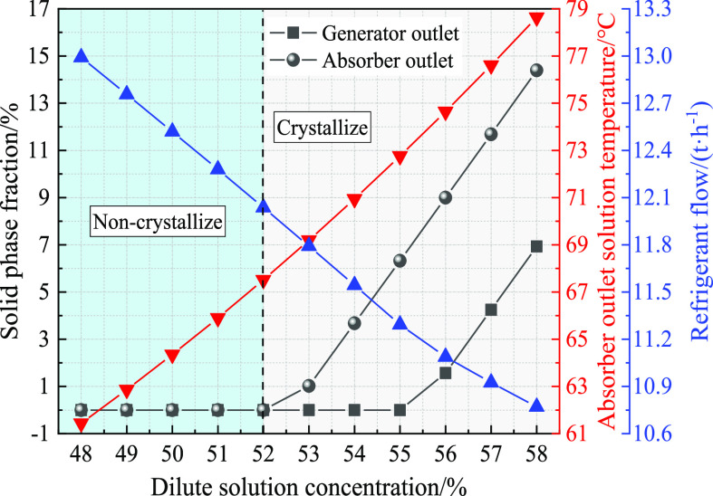
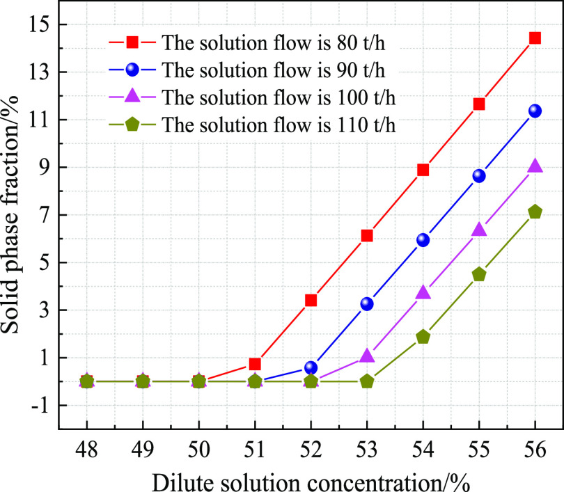
Based on the refrigerant absorption process and refrigerant regeneration process by the lithium bromide solution, the absorption heat pump completes the refrigerant circulation process. The lithium bromide dilute solution is heated in the generator, and the refrigerant vapors from the lithium bromide dilute solution are generated. Subsequently, the lithium bromide concentration solution enters the absorber after the temperature is decreased by the solution heat exchanger. As shown in Figure 8, when the lithium bromide solution flow is 100 t/h at the generator inlet, with increasing the concentration of lithium bromide solution, the solid crystals are gradually precipitated at the generator outlet and the absorber inlet. With increasing lithium bromide solution flow, the critical concentration of lithium bromide solution is higher where the solid crystals appear. The lithium bromide solution at the absorber inlet earlier appears as solid crystals compared to the lithium bromide solution at the generator outlet. It is shown that the crystallization phenomenon of lithium bromide solutions at the absorber outlet in Figure 9. When the lithium bromide solution flow is 80, 90, 100, and 110 t/h, the critical concentrations of the lithium bromide solution between the crystalline zones and noncrystalline zones are 50, 51, 52, and 53%, respectively. For a defined concentration of the lithium bromide solution, with the concentration of the lithium bromide solution increasing, the saturation temperature of the lithium bromide solution gradually increases at the absorber outlet; however, the refrigerant flow gradually decreases at the generator outlet. The reason is that there is a lower saturated pressure with the higher concentration for lithium bromide solution. In order to meet the same pressure conditions, the saturated temperature of lithium bromide solution will inevitably be increased, which will result in a higher sensible heat percentage by the lithium bromide solution and a lower latent heat percentage by refrigerant. The refrigerant flow reduction leads to the lower absorption heat pump COP, which is consistent with the literature.13 The literature13 uses calcium chloride solution as the dehumidification solution, and the lithium bromide solution is used as the dehumidification solution in this paper. Both the calcium chloride solution and the lithium bromide solution have some dehumidification properties. In order to ensure the operational safety of the absorption heat pump, the concentration selection and the flow selection of lithium bromide dilute solution should be comprehensively considered in the absorption heat pump.
Figure 8.
Effect of the lithium bromide solution concentration parameters.
Figure 9.
Crystallization phenomenon of lithium bromide solution.
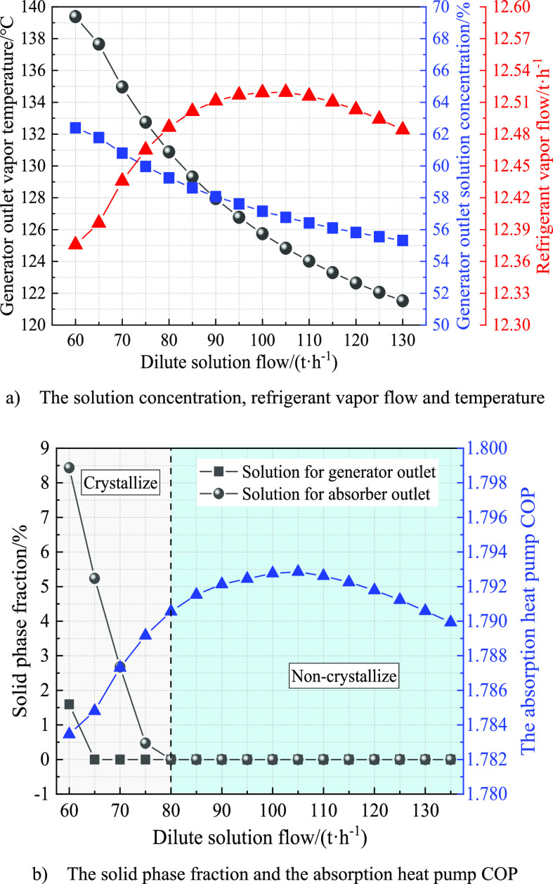
The lithium bromide solution concentration is 50%. As shown in Figure 10a, with increasing lithium bromide solution flow, the refrigerant temperature is gradually reduced at the generator outlet, and the lithium bromide solution concentration is also gradually reduced at the generator outlet. Moreover, with increasing the lithium bromide solution flow, a changing trend is shown that first increases and then decreases for the refrigerant liquid flow at the generator outlet. In Figure 10b, as the lithium bromide solution flow increases, the crystallization phenomenon of the lithium bromide solution gradually disappears at the absorber inlet. The crucial flow of the lithium bromide solution is 80 t/h between the crystalline zone and the noncrystalline zone, which is consistent with Figure 7. In addition, with increasing lithium bromide solution flow, a trend is also shown that first increases and then decreases for the absorption heat pump COP. When the lithium bromide solution flow is 105 t/h, the refrigerant flow is 12.52 t/h, and the absorption heat pump COP is 1.79. The lithium bromide solution with a lower concentration corresponds to the refrigerant vapor with a higher saturated pressure. Thus, increasing the refrigerant liquid flow at the generator outlet, the absorption heat pump COP rises. However, when the lithium bromide solution flow is increased to a certain value, the sensible heat absorption increases sharply for lithium bromide solution, the latent heat absorption decreases accordingly for refrigerant vapor, and the refrigerant vapor flow decreases at the generator outlet.
Figure 10.
Effects of lithium bromide dilute solution flow parameters.
3.2. Operational Characteristics of Turbine Extraction Steam
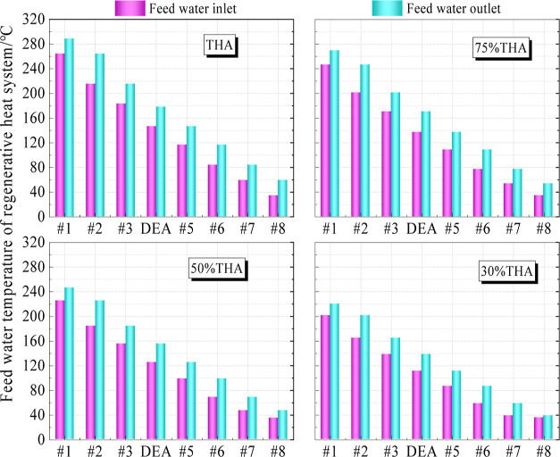
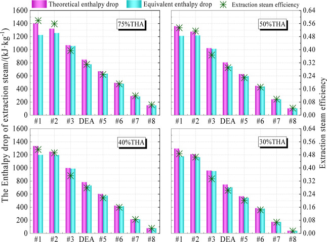
There are eight stages with turbine extraction steam arranged in the regenerative heat system. In Table 1, it can be seen that the extraction steam pressure decreases sequentially as the serial number of return heater increases. However, the extraction steam temperature shows a changing trend that first decreases then increases and finally decreases because of the primary intermediate reheating process of the turbine in the coal-fired plant. Figure 11 shows the variation trend of feedwater temperature in the regenerative heat system. The feedwater temperature gradually decreases with the serial number of the return heater increases. Under design operation conditions, the inlet/outlet temperatures of feedwater are 83.8/116.5, 59.2/83.8, and 34.3/83.8 in the low-pressure heaters at #6, #7, and #8, respectively. The enthalpy drop of extraction steam and extraction steam efficiency both reflect the work capacity of extraction steam. Figure 12 shows that the equivalent enthalpy drop of extraction steam is slightly lower than the theoretical enthalpy drop of extraction steam, and the difference between the equivalent enthalpy and the theoretical enthalpy is more obvious in the high-pressure heaters. The reason is that the drain heat of extraction steam decreases with the extraction steam flow decreases, and the lacking drain heat needs to be supplemented by more extraction steam in the next return heaters. At the same time, the extraction steam efficiency decreases significantly with the serial number of return heater increases. Under the design operation condition, and the extraction steam efficiencies are 0.188, 0.114, and 0.057 in the #6, #7, and #8 low-pressure heaters. The reducing turbine extraction steam leads to a higher flow of condensation water in the condenser, and the extraction steam flow also grows slightly to heat the feedwater. Additionally, it can also be seen that the feedwater temperature and extraction steam parameters in the same return heater are not the same with different working conditions, and they significantly decrease with the electricity generation reduction in the coal-fired power plant.
Figure 11.
Inlet/outlet temperature parameters of boiler feedwater.
Figure 12.
Enthalpy drop and extraction steam efficiency of turbine extraction steam.
3.3. Operational Characteristics of Flue Gas Waste Heat Recovery System
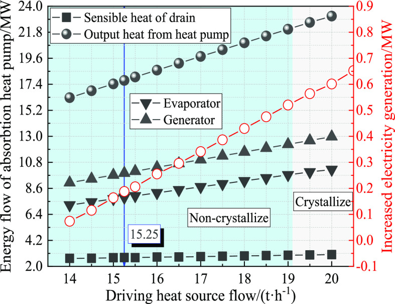
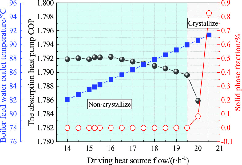
The driving heat source of the absorption heat pump is the turbine extraction steam of the #6 low-pressure heater. As shown in Figure 13, the sensible heat of steam drain is affected little by the extraction steam flow. Moreover, the evaporator energy flow, absorber energy flow, and output energy flow in the absorption heat pump all increase with increasing the extraction steam flow. At the same time, it can be seen that the boiler feedwater temperature at the absorption heat pump outlet increases linearly with the extraction steam flow of the driving heat source. The electricity generation of the coal-fired power plant also increases, which is consistent with the research conclusion of the literature.39 The feedwater temperature at the #6 low-pressure heater inlet is 83.8 °C, and the extraction steam flow is only 15.25 t/h for the absorption heat pump to meet the requirements. At the same time, the electricity generation increased is 0.19 MW in the coal-fired power plant. It can be seen in Figure 14 that the absorption heat pump COP shows a decreasing trend by increasing the extraction steam flow. When the driving heat source is above 19.5 t/h, there is the risk of crystallization in the absorption heat pump. The reason is that the lithium bromide solution concentration is increased with increasing the extraction steam as the driving heat source. Moreover, the cooling process can also cause the crystallization phenomenon in lithium bromide solution with high concentrations. Consequently, when the driving heat source is 14–19.5 t/h in the absorption heat pump, the saturated flue gas waste heat recovery system can recover low-grade heat source 7.19–9.99 MW and increase electricity generation 0.07–0.56 MW in the coal-fired power plant.
Figure 13.
Energy flow analysis of saturated flue gas waste heat recovery system.
Figure 14.
Operational performance analysis of the absorption heat pump.
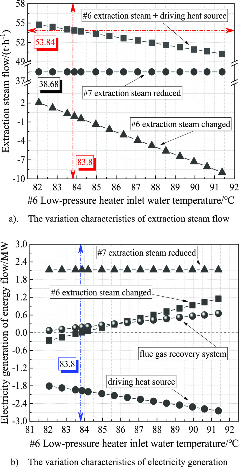
The condenser of absorption heat pump is connected to the #6 low-pressure heater, and the feedwater is sent to the #6 low-pressure heater after absorbing heat in the absorption heat pump. As shown in Figure 15a, the #7 extraction steam flow reduced is not affected by the inlet feedwater temperature of #6 low-pressure heater. At the same time, the extraction steam flow sum of the #6 low-pressure heater and driving heat source decreases with increasing #6 low-pressure heater inlet water temperature. In the regenerative heat system, the design flow of the extraction steam is 53.84 t/h in the #6 low-pressure heater, and the design feedwater temperature is 83.8 °C at the #6 low-pressure heater inlet. When the feedwater temperature is higher or lower than the design temperature at the #6 low-pressure heater inlet, the corresponding extraction steam flow will be reduced or increased, which in turn will have an impact on the electricity generation. As can be seen in Figure 15b, the change in characterization of electricity generation is composed by three components. First, the extraction steam of the #7 low-pressure heater returns to the turbine and continues to do work, corresponding to the electricity generation being 2.13 MW. Then, the driving heat source is the extraction steam of the #6 low-pressure heater, corresponding to the electricity generation being −1.81 ∼ −2.65 MW and the driving heat source flow is 14–20.5 t/h. Finally, when the feedwater temperature is greater than the design value at 0.3–4.6 °C at the #6 low-pressure heater inlet, the extraction steam flow reduced and can add an electricity generation of 0.06–1.15 MW. However, when the feedwater temperature is less than the design value at 0.4–1.8 °C at the #6 low-pressure heater inlet, the extraction steam flow increased and can reduce the electricity generation by 0.04–0.26 WM.
Figure 15.
Effects of feedwater temperature at the #6 low-pressure heater inlet.
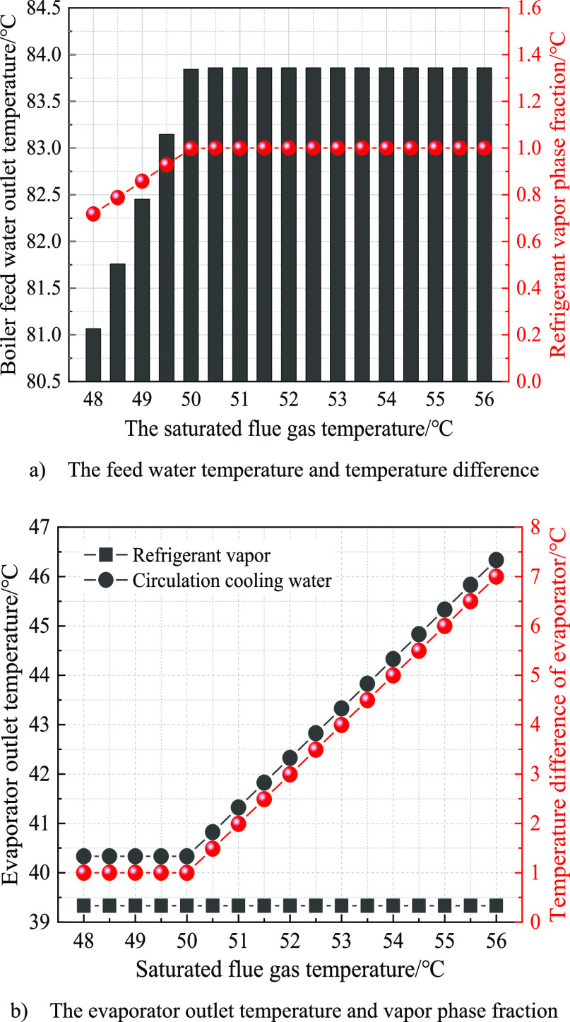
The saturated flue gas temperature is an important parameter for flue gas waste heat, which directly affects the stability of a low-grade heat source in the absorption heat pump. In Figure 16a, when the flue gas temperature is lower than 50 °C, the feedwater at the #6 low-pressure heater inlet does not reach the design value, which is 83.9 °C. It can be also seen in Figure 16a, the reason is that the evaporator does not absorb enough heat and the vapor phase fraction of refrigerant at the evaporator outlet is less than 1. At the same time, when the flue gas temperature is higher than 50 °C, the feedwater temperature at the #6 low-pressure heater inlet and the vapor phase fraction at the evaporator outlet both meet the design requirements. Combined with Figure 16b, by setting the heat-transfer difference to not less than 1 °C and no overheating phenomenon of refrigerant vapor in the evaporator, the saturated temperature of refrigerant vapor is constant. Along with the increasing saturated flue gas temperature, the circulation cooling water temperature increases at the evaporator outlet, and the heat-transfer efficiency is also significantly improved. For the same heat-transfer area, it is helpful to increase the heat-transfer ratio by increasing the heat-transfer temperature difference.
Figure 16.
Effects of saturated flue gas temperature for waste heat recovery system.
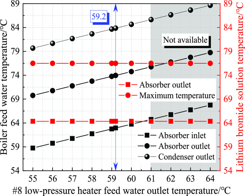
In the saturated flue gas waste heat recovery system, the boiler feedwater recovers part of the sensible heat of steam drain from the #7 low-pressure heater. Subsequently, the feedwater is reheated by the absorber and condenser in the absorption heat pump. Figure 17 illustrates the influence characteristics of the boiler feedwater temperature at the #8 low-pressure heater outlet. The lithium bromide solution temperature at the absorber outlet and the maximum saturation temperature in the absorber are not affected with the boiler feedwater temperature because the absorber has a certain pressure. The boiler feedwater temperature increases at the absorber outlet with the boiler feedwater temperature increasing at the #8 low-pressure heater outlet, and the boiler feedwater temperature also increases at the condenser outlet, which is consistent with the conclusion of literature.40 However, when the boiler feedwater temperature increases to 61 °C at the #8 low pressure heater outlet, the boiler feedwater temperature is higher at the absorber inlet than the lithium bromide solution temperature at the absorber outlet, which violates the laws of thermodynamics and is not achievable.
Figure 17.
Effects of boiler feedwater temperature at the #8 low-pressure heater outlet.
4. Conclusions
This paper discusses the waste heat losses caused by the saturated flue gas discharge and also analyzes the operation parameters of the regenerative heat system in the coal-fired plant. On this basis, the saturated flue gas waste heat recovery system was constructed with the absorption heat pump. The flue gas waste heat is used to reduce the extraction steam of low-pressure heaters and increase the electricity generation in a coal-fired power plant. Combined with the typical 350 MW coal-fired power plant, the operation parameters of the absorption heat pump are analyzed. Moreover, the operation performances of the flue gas waste heat recovery system is revealed.
-
(1)
The internal parameters have the important influence on the operational performances of the absorption heat pump. The lower throttle pressure reduces the waste heat temperature of flue gas, which can be recovered, but weakens the operation performance of absorption heat pump. The higher generator pressure not only increases the refrigerant vapor temperature but also weakens the operational performance of absorption heat pump. The higher lithium bromide solution concentration increases the refrigerant vapor temperature but has a risk of crystallization in the lithium bromide solution. The higher lithium bromide solution flow avoids crystallization but reduces the refrigerant vapor temperature, and the operation performance of the absorption heat pump is first increased and then reduced.
-
(2)
The extraction steam efficiency is calculated by equivalent enthalpy drop. The extraction steam efficiency decreases significantly with the serial number of the return heater increasing. The boiler feedwater temperatures is 59.2 °C at the #7 low-pressure heater inlet, and the boiler feedwater temperature is 83.8 °C at the #7 low-pressure heater outlet. The extraction steam efficiency is 0.19 in the #6 low-pressure heater, and the extraction steam efficiency is 0.11 in the #7 low-pressure heater. When the flue gas temperature is 52 °C, the saturated flue gas waste heat is recovered by the absorption heat pump, and it is the appropriate temperature for reducing the turbine extraction steam of #7 low-pressure heater.
-
(3)
The turbine extraction steam of #6 low-pressure heater is used as the driving heat source in the absorption heat pump. The saturated flue gas waste heat is recovered from 7.19 to 9.99 MW, which correspondingly increases the electricity generation by 0.07–0.56 MW in the coal-fired power plant. When the driving heat source flow is 19.5 t/h, the absorption heat pump recovers the saturated flue gas waste heat up to 9.99 MW, and electricity generation of 0.56 MW is added. When the actual temperature of the boiler feedwater at the absorption heat pump outlet is higher than the design temperature of the boiler feedwater at the #6 low-pressure heater inlet, the flue gas waste heat recovery system can reduce the turbine extraction steam of #6 low-pressure heater. Moreover, it helps to increase the electricity generation in the coal-fired power plant but corresponding to the high flow of the driving heat source will cause crystallization of the lithium bromide solution in the absorption heat pump.
Acknowledgments
This work is financially supported by the National Key R&D Program of China (2022YFC3701503) and Technology Program of Company (LYHB-23-02).
Author Contributions
Conceptualization, Ou Chen; methodology, Guangjie Lu; formal analysis, Dongxue Bi; investigation, Qijiu Zhang; resources, Li Li; data curation, Da Teng; writing-original draft preparation, Da Teng; and writing-review & editing, Da Teng.
The authors declare no competing financial interest.
References
- Davies G.; Lagoeiro H.; Turnell H.; Wegner M.; Foster A.; Evans J.; Revesz A.; Leiper A.; Smyth K.; Hamilton J.; Cooke H.; Maidment G. Evaluation of Low Temperature Waste Heat as a Low Carbon Heat Resource in the UK. Appl. Therm. Eng. 2023, 235, 121283. 10.1016/j.applthermaleng.2023.121283. [DOI] [Google Scholar]
- Yoo H.; Roh K.; Hunaidy A. S. A.; Imran H.; Lee J. H. Optimal Design of Heat and Water Recovery System Utilizing Waste Flue Gases for Refinery CO2 Reduction. Comput. Chem. Eng. 2019, 124, 140–152. 10.1016/j.compchemeng.2019.02.015. [DOI] [Google Scholar]
- Noroozian A.; Mohammadi A.; Bidi M.; Ahmadi M. H. Energy Exergy and Economic Analyses of a Novel System to Recover Waste Heat and Water in Steam Power Plants. Energy Convers. Manage. 2017, 144, 351–360. 10.1016/j.enconman.2017.04.067. [DOI] [Google Scholar]
- Jin Y.; Gao N.; Zhu T. Techno-Economic Analysis on a New Conceptual Design of Waste Heat Recovery for Boiler Exhaust Flue Gas of Coal-Fired Power Plants. Energy Convers. Manage. 2019, 200, 112097. 10.1016/j.enconman.2019.112097. [DOI] [Google Scholar]
- Zhao S.; Du X.; Ge Z.; Yang Y. Cascade Utilization of Flue Gas Waste Heat in Combined Heat and Power System with High Back-Pressure (CHP-HBP). Energy Procedia 2016, 104, 27–31. 10.1016/j.egypro.2016.12.006. [DOI] [Google Scholar]
- Zajacs A.; Bogdanovics R.; Borodinecs A. Analysis of Low Temperature Lift Heat Pump Application in a District Heating System for Flue Gas Condenser Efficiency Improvement. Sustain. Cities Soc. 2020, 57, 102130. 10.1016/j.scs.2020.102130. [DOI] [Google Scholar]
- Wang X.; Zhuo J.; Liu J.; Li S. Synergetic Process of Condensing Heat Exchanger and Absorption Heat Pump for Waste Heat and Water Recovery from Flue Gas. Appl. Energy 2020, 261, 114401. 10.1016/j.apenergy.2019.114401. [DOI] [Google Scholar]
- Darake S.; Hatamipour M. S.; Rahimi A. P.; Hamzeloui P. Hamzaloui, SO2 Removal by Seawater in a Spray Tower: Experimental Study and Mathematical Modeling. Chem. Eng. Res. Des. 2016, 109, 180–189. 10.1016/j.cherd.2015.11.027. [DOI] [Google Scholar]
- Xiong Y.; Tan H.; Wang Y.; Xu W.; Mikulčić H.; Duić N. Pilot-Scale Study on Water and Latent Heat Recovery from Flue Gas Using Fluorine Plastic Heat Exchangers. J. Clean. Prod. 2017, 161, 1416–1422. 10.1016/j.jclepro.2017.06.081. [DOI] [Google Scholar]
- Men Y.; Liu X.; Zhang T. Analytical Solutions of Heat and Mass Transfer Process in Combined Gas-Water Heat Exchanger Applied for Waste Heat Recovery. Energy 2020, 206, 118095. 10.1016/j.energy.2020.118095. [DOI] [Google Scholar]
- Chen W.; Shi W.; Wang B.; Shang S.; Li X. A Deep Heat Recovery Device Between Flue Gas and Supply Air of Gas-Fired Boiler by Using Non-Contact Total Heat Exchanger. Energy Procedia 2017, 105, 4976–4982. 10.1016/j.egypro.2017.03.994. [DOI] [Google Scholar]
- Wang Z.; Zhang X.; Li Z. Evaluation of a Flue Gas Driven Open Absorption System for Heat and Water Recovery from Fossil Fuel Boilers. Energy Convers. Manage. 2016, 128, 57–65. 10.1016/j.enconman.2016.09.050. [DOI] [Google Scholar]
- Zhang H.; Dong Y.; Lai Y.; Zhang H.; Zhang X. Waste Heat Recovery from Coal-Fired Boiler Flue Gas: Performance Optimization of a new Open Absorption Heat Pump. Appl. Therm. Eng. 2021, 183, 116111. 10.1016/j.applthermaleng.2020.116111. [DOI] [Google Scholar]
- Ma H.; Liang N.; Liu Y.; Luo X.; Hou C.; Wang G. Experimental Study on Novel Waste Heat Recovery System for Sulfide-Containing Flue Gas. Energy 2021, 227, 120479. 10.1016/j.energy.2021.120479. [DOI] [Google Scholar]
- Stevanovic V. D.; Petrovic M. M.; Wala T.; Milivojevic S.; Ilic M.; Muszynski S. Efficiency and Power Upgrade at the Aged Lignite-Fired Power Plant by Flue Gas Waste Heat Utilization: High Pressure Versus Low Pressure Economizer Installation. Energy 2019, 187, 115980. 10.1016/j.energy.2019.115980. [DOI] [Google Scholar]
- Jia G.; Cai M.; Xu W.; Shi Y. Energy Conversion Characteristics of Reciprocating Piston Quasi-Isothermal Compression Systems Using Water Sprays. Sci. China Technol. Sci. 2018, 61, 285–298. 10.1007/s11431-017-9175-3. [DOI] [Google Scholar]
- Javed K. H.; Mahmud T.; Purba E. Enhancement of Mass Transfer in a Spray Tower Using Swirling Gas Flow. Chem. Eng. Res. Des. 2006, 84, 465–477. 10.1205/cherd.05119. [DOI] [Google Scholar]
- Wei H.; Huang S.; Zhang X. Experimental and Simulation Study on Heat and Mass Transfer Characteristics in Direct-Contact Total Heat Exchanger for Flue Gas Heat Recovery. Appl. Therm. Eng. 2022, 200, 117657. 10.1016/j.applthermaleng.2021.117657. [DOI] [Google Scholar]
- Cui Z.; Du Q.; Gao J.; Bie R. Optimum Design of a Deep Cooling Tower for Waste Heat and Water Recovery from Humid Flue Gas. Case Stud. Therm. Eng. 2023, 49, 103317. 10.1016/j.csite.2023.103317. [DOI] [Google Scholar]
- Yang B.; Jiang Y.; Fu L.; Zhang S. Experimental and Theoretical Investigation of a Novel Full-Open Absorption Heat Pump Applied to District Heating by Recovering Waste Heat of Flue Gas. Energy Build. 2018, 173, 45–57. 10.1016/j.enbuild.2018.05.021. [DOI] [Google Scholar]
- Kashif Shahzad M.; Ding Y.; Xuan Y.; Gao N.; Chen G. Performance Analysis of a Novel Double Stage Multifunctional Open Absorption Heat Pump System: an Industrial Moist Flue Gas Heat Recovery Application. Energy Convers. Manage. 2022, 254, 115224. 10.1016/j.enconman.2022.115224. [DOI] [Google Scholar]
- Ji L.; Shukla S. K.; Zuo Z.; Lu X.; Ji X.; Wang C. An Overview of the Progress of New Working Pairs in Absorption Heat Pumps. Energy Rep. 2023, 9, 703–729. 10.1016/j.egyr.2022.11.143. [DOI] [Google Scholar]
- Zhu X.; Sui X.; Zhao Y.; Meng J.; Li Z. Experimental Study of the Flow and Heat Transfer of a Gas-Water Mixture Through a Packed Channel. Sci. Bull. 2016, 61, 406–415. 10.1007/s11434-016-1018-x. [DOI] [Google Scholar]
- Zhang Q.; Huang H.; Zhai H.; Zhao W.; Lu X. Experimental Research on Direct Expansion Heat Pump Flue Gas Waste Heat Recovery and Humidification Nitrogen Reduction System. J. Clean. Prod. 2023, 406, 137000. 10.1016/j.jclepro.2023.137000. [DOI] [Google Scholar]
- Zhang Q.; Niu Y.; Yang X.; Sun D.; Xiao X.; Shen Q.; Wang G. Experimental Study of Flue Gas Condensing Heat Recovery Synergized with Low NOx Emission System. Appl. Energy 2020, 269, 115091. 10.1016/j.apenergy.2020.115091. [DOI] [Google Scholar]
- Hsieh J. C.; Lai C. C.; Chen Y. H. Thermoeconomic Analysis of a Waste Heat Recovery System with Fluctuating Flue Gas Scenario. Energy 2022, 258, 124866. 10.1016/j.energy.2022.124866. [DOI] [Google Scholar]
- Sun J.; Fu L.; Zhang S.; Hou W. A Mathematical Model with Experiments of Single Effect Absorption Heat Pump Using LiBr-H2O. Appl. Therm. Eng. 2010, 30, 2753–2762. 10.1016/j.applthermaleng.2010.07.032. [DOI] [Google Scholar]
- Shahzad M. K.; Ding Y.; Xuan Y.; Gao N.; Chen G. Modelling and Performance Analysis of a Single Stage Open Absorption Heat Pump System in Aspen Plus Using Aqueous LiBr and HCOOK a Waste Moist Heat Recovery Application. Proc. IME J. Power Energy 2022, 236, 538–554. 10.1177/09576509211047831. [DOI] [Google Scholar]
- Wu Z.; Jiang Y.; Wang Y.; You S.; Zhang H.; Liu S.; Fan X.; Pu J.; Wan Z.; Sha L.; Wei S. Investigating the Performance of Heat Exchangers in Absorption Heat Pump Systems Using both Numerical and Experimental Methods. Energy Convers. Manage. 2023, 278, 116744. 10.1016/j.enconman.2023.116744. [DOI] [Google Scholar]
- Wang X.; Zhang H.; Cui L.; Wang J.; Lee C.; Dong Y. Simulation Study of an Open Compression Absorption Heat Pump in Water and Heat Recovery of Low-Temperature and High-humidity Flue Gas. Energy Convers. Manage. 2022, 269, 116180. 10.1016/j.enconman.2022.116180. [DOI] [Google Scholar]
- Liu C.; Han W.; Xue X. Experimental Investigation of a High-Temperature Heat Pump for Industrial Steam Production. Appl. Energy 2022, 312, 118719. 10.1016/j.apenergy.2022.118719. [DOI] [Google Scholar]
- Xie X.; Yi Y.; Zhang H.; Jiang Y. Theoretical Model of Absorption Heat Pump from Ideal Solution to Real Solution: Temperature Lift Factor Model. Energy Convers. Manage. 2022, 271, 116328. 10.1016/j.enconman.2022.116328. [DOI] [Google Scholar]
- Gao D.; Li Z.; Zhang H.; Chen H.; Cheng C.; Liang K. Moisture and Latent Heat Recovery from Flue Gas by Nonporous Organic Membranes. J. Clean. Prod. 2019, 225, 1065–1078. 10.1016/j.jclepro.2019.03.326. [DOI] [Google Scholar]
- Terhan M.; Comakli K. Design and Economic Analysis of a Flue Gas Condenser to Recover Latent Heat from Exhaust Flue Gas. Appl. Therm. Eng. 2016, 100, 1007–1015. 10.1016/j.applthermaleng.2015.12.122. [DOI] [Google Scholar]
- Wang Y.; Chen Y.; Wang K.; Li X. Performance Evaluation and Thermal Analysis of Heat Pipe Flue Gas Waste Heat Utilization System. Energy Rep. 2022, 8, 210–217. 10.1016/j.egyr.2022.03.100. [DOI] [Google Scholar]
- Thiyagu S.; Naveen T. K.; Siddharthan B.; Manirathnam A. S. Numerical Investigation and Performance Enhancement of 210 MW Boiler by Utilization of Waste Heat in Flue Gas. Mater. Today 2020, 33, 756–762. 10.1016/j.matpr.2020.06.119. [DOI] [Google Scholar]
- Jeong S.; Kang B. H.; Karng S. W. Dynamic Simulation of an Absorption Heat Pump for Recovering Low Grade Waste heat. Appl. Therm. Eng. 1998, 18, 1–12. 10.1016/S1359-4311(97)00040-9. [DOI] [Google Scholar]
- Huicochea A. A Novel Advanced Absorption Heat Pump (Type III) for Cooling and Heating Using Low-Grade Waste Heat. Energy 2023, 278, 127938. 10.1016/j.energy.2023.127938. [DOI] [Google Scholar]
- Fan X.; Pu J.; Wu Z.; Wang Y.; You S.; Zhang H.; Liu J.; Jiang Y.; Liu S.; Wan Z. Thermodynamic Performance and Heat and Mass Transfer Analysis of Air Source Absorption Heat Pump for Heating. J. Build. Eng. 2023, 76, 107390. 10.1016/j.jobe.2023.107390. [DOI] [Google Scholar]
- Hu X.; Zhang S.; Peng Z.; Tang S.; Liu N. Dynamic Modeling and Operation Characteristics Analysis of LiBr Absorption Heat Pump. E3S Web Conf. 2021, 257, 01022. 10.1051/e3sconf/202125701022. [DOI] [Google Scholar]


