

Abstract
The anti-symmetric and anisotropic symmetric exchange interactions between two magnetic dipole moments – responsible for intriguing magnetic textures (e.g., magnetic skyrmions) – have been discovered since last century, while their electric analogues were either hidden for a long time or still not known. It is only recently that the anti-symmetric exchange interactions between electric dipoles was proved to exist (with materials hosting such an interaction being still rare) and the existence of anisotropic symmetric exchange interaction between electric dipoles remains ambiguous. Here, by symmetry analysis and first-principles calculations, we identify hafnia as a candidate material hosting the non-collinear dipole alignments, the analysis of which reveals the anti-symmetric and anisotropic symmetric exchange interactions between electric dipoles in this material. Our findings can hopefully deepen the current knowledge of electromagnetism in condensed matter, and imply the possibility of discovering novel states of matter (e.g., electric skyrmions) in hafnia-related materials.
Subject terms: Ferroelectrics and multiferroics, Ferroelectrics and multiferroics
Materials exhibiting anti-symmetric exchange interactions between electric dipoles are rare and the existence of the symmetric exchange interactions remains ambiguous. Here, authors identify hafnia as a candidate hosting such interactions by symmetry analysis and first-principles calculations.
Introduction
In the last century, the profound exchange couplings between magnetic dipole moments—namely, the magnetic anti-symmetric exchange interactions (also termed as magnetic Dzyaloshinskii–Moriya interaction, mDMI) and the magnetic anisotropic symmetric exchange interaction (mASEI)—were derived with the origin attributed to spin–orbit interaction (see e.g., refs. 1–3). The mDMI and mASEI are physical underpinnings for many intriguing non-collinear magnetic textures (e.g., magnetic vortices4,5, skyrmions6–13, and merons12–15) that are promising for novel device applications in information technology16–18. Strikingly, electric vortices, skyrmions and merons have also been observed and/or predicted in ferroelectric nanostructures such as Pb(Zr,Ti)O3 nanodisks, nanorods and thin films19–21, BaTiO3–SrTiO3 nanocomposites22, PbTiO3 thin films23, PbTiO3 nanodomains24 and SrTiO3/PbTiO3 superlattices25–29. Unlike the non-collinear magnetic textures, the mechanisms for these non-collinear dipolar textures were mostly ascribed to the depolarizing field or the Bloch-like domain walls, instead of the exchange interactions between electric dipoles19,22–29. To understand the non-collinear ferroelectricity in bulk materials (i.e., with no depolarizing field or domain wall)30–36, the exchange interactions between electric dipoles were recently revisited, yielding the disclosure of the electric DMI (eDMI)37–39—which may also be responsible for the recently observed and so-called double-Q-modulated structure40. Even so, materials that are known to host eDMI are rather rare and elusive in nature. Besides, whether there is electric anisotropic symmetric exchange interaction (eASEI) is currently ambiguous.
Here, via symmetry analysis and first-principles calculations, we identify hafnia (HfO2) material as an ideal candidate that accommodates the eDMI and eASEI between electric dipoles. We show that HfO2 has various polymorphisms (i.e., P21/c, Pmn21, Pca21, and Pbca phases) demonstrating non-collinear alignments of electric dipoles. The non-collinear dipole patterns (NCDP) herein are interpreted by our phenomenological theories, revealing the existence of eDMI which stems from the structural distortions associated with the oxygen sublattice. We further identify the eAESI in HfO2 (irrelevant to the NCDP), contributed by the oxygen-sublattice structural distortions as well as the long-range and short-range dipolar interactions.
Results
The NCDP in HfO2’s structural phases
Experimentally, HfO2 was found to be polymorphic, with a variety of structural phases such as 41, P42/nmc42, Pbca43, Pnma44, Pbcm45, Pca2146, and P21/c47. Recent works by first-principles simulations also highlight the possibility of achieving the polar Pmn21 phase of HfO2 (see, e.g., refs. 48–50). Of particular interest are the P21/c, Pmn21, Pca21 and Pbca phases. As will be shown below, these phases exhibit NCDP, and analyzing these NCDP enables the disclosure of the eDMI and eASEI in HfO2. In the following, we represent the electric dipoles in structural phases of HfO2 by the displacements of Hf ions, with respect to their positions in the reference structure. We shall show that the non-collinear alignments of dipoles in P21/c, Pmn21, Pca21, and Pbca phases can be well understood by investigating the structural distortions of HfO2. The possible structural distortions in HfO2 are described in Fig. 1 with the conventional cell of HfO2 being selected as our reference structure. The reasons for such a selection are as follows. First, our symmetry analysis based on the conventional cell of HfO2 can well describe the NCDP in P21/c, Pmn21, Pca21 and Pbca phases. Second, using a larger cell, although capturing more abundant structural distortions and NCDP, will significantly increase the difficulties for our symmetry analysis.
Fig. 1. The possible structural distortions in hafnia with respect to its cubic phase.

a The conventional cell of the cubic phase. b, c The sublattices made of Hf and O ions. d Four lattice modes associated with the Hf sublattice. e Definitions for the structural distortions. The combination of -type lattice mode and atomic displacement uα (α = x, y, z) yields the structural distortions. f Eight lattice modes associated with the O sublattice. g The collinear dipole patterns resulting from the combination of and distortions. h The collinear dipole patterns resulting from the combination of and distortions. i The non-collinear dipole patterns resulting from the combination of and distortions. The Hf and O ions are denoted by cyan and yellow spheres. The atomic displacement uα is represented by blue arrows. In b, each Hf ion is numbered by τ (τ = 1, 2, 3, 4). In d and f, the “+” and “−” signs indicate that the atomic displacement uα centered on that corresponding Hf or O site is along the +α and −α directions, respectively.
Now, we analyze the possible structural distortions accommodated by the high-symmetric phase of HfO2, prior to extracting the NCDP in P21/c, Pmn21, Pca21 and Pbca phases. As shown in Fig. 1a, the conventional cell of HfO2 is composed of two sublattices made of Hf ions (see Fig. 1b) and O ions (see Fig. 1c). The Hf sublattice hosts four types of lattice modes sketched in Fig. 1d and labeled by (U = F, X, Y, Z). By linking the mode with uα [i.e., atomic displacement along α direction (α = x, y, z)], we arrive at the structural distortion mode —termed as “order parameter” in the following. For example, the definitions of and order parameters are depicted by the red dash arrow, yellow solid arrow, and purple dot arrow, respectively (Fig. 1e). Similarly, we can define the other order parameters associated with Hf sublattice (Fig. 1d) and those contributed by the O sublattice (Fig. 1f) in a self-explanatory manner. In this regard, the order parameters associated with Hf and O sublattices are symbolized as and , respectively. Here, the superscript U or W indicates the lattice mode (Fig. 1d, f) and the subscript α or γ marks the direction of the atomic displacements. Following this convention, we have identified thirty-six order parameters for HfO2 [see Supplementary Note 1 in the Supplementary Information (SI) for details].
Starting from these thirty-six order parameters, we construct phenomenological theories that describe the NCDP in HfO2. We notice that the combination of and order parameters naturally yields NCDP, when U ≠ V and α ≠ β (see Fig. 1g–i). By symmetry arguments, and are possibly coexisting via the trilinear coupling, that mediated by the structural order parameter. As shown in Supplementary Note 1 of the SI, we have derived four effective Hamiltonians (H1–H4) involving trilinear couplings of our aforementioned kind, summarized in Table 1. We can verify the existence of the couplings in Hl (l = 1 − 4) by first-principles numerical calculations, using the following strategy (see Methods for details): to verify the coupling, we (i) start from the phase and impose a structural distortion according to with fixed amplitude, (ii) displace Hf ions following mode with varying magnitude, and (iii) measure the first-principles-calculated forces acting on the Hf sublattice and associated with the mode. The linear relationship between these forces (related to ) and the distortion amplitudes (of ) will corroborate the existence of the coupling. Figure 2 indeed numerically confirms the existence of several selective trilinear couplings, namely, and . For instance, the fittings in Fig. 2b—with the R2 (i.e., coefficient of determination) exceeding 0.999—indicate the linear dependence of and on . The fitting slopes of 14.58 eV Å−2 for and 11.04 eV Å−2 for show that the and terms contribute unequally in HfO2. Interestingly, our derived coupling coincides with the trilinear coupling that was claimed to drive the ferroelectricity of Pca21 HfO2 (see ref. 51).
Table 1.
Trilinear couplings resulting in non-collinear dipole patterns for various phases of hafnia
| Hamiltonian | Phases |
|---|---|
Here, the definitions of the notations (e.g., and ) are indicated in Fig. 1. The trilinear coupling associated with a specific phase of HfO2 is shown in the parentheses after the space group of that phase.
Fig. 2. Numerical verification of various trilinear couplings in hafnia.
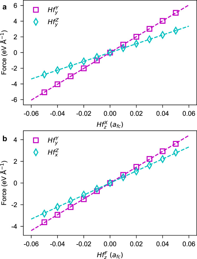
a Forces on Hf sublattice as a function of distortion. b Forces on Hf sublattice as a function of distortion. Purple square in (a): forces associated with mode in ( being fixed). Cyan diamond in a: forces associated with mode in ( being fixed). Purple square in b: forces associated with mode in ( being fixed). Cyan diamond in (b): forces associated with mode in ( being fixed). The dash lines in a and b display the linear fitting results.
By analyzing the structural distortions in P21/c, Pmn21, Pca21 and Pbca phases, we are able to extract the NCDP in HfO2 and link the NCDP to our derived trilinear couplings. Such detailed analysis can be found in Supplementary Note 2 of the SI. Here, we provide a graphical approach to “visualize” how our theories interpret the NCDP in HfO2 (see Fig. 3). Sketched in Fig. 3a, the and couple with each other via the intermediate distortion. In such sense, the distortion will lead to (via ) and vice versa— and coexisting. In the P21/c phase, the and trilinear couplings—shown in Table 1—imply the and combinations, respectively, yielding NCDP (Fig. 3b and h). As shown in Fig. 3c, f and g, the NCDP in Pca21 phase come from the and combinations, rooted in the and trilinear couplings (see Table 1 as well). Furthermore, the and couplings lead to the NCDP in Pmn21 phase [via and combinations, see Fig. 3e, f], while the coupling gives rise to the NCDP in the Pbca phase [via combination, see Fig. 3d]. Our aforementioned analysis thus emphasizes the importance of the -type of trilinear couplings (U ≠ V, α ≠ β) towards the NCDP in HfO2’s structural phases. Here, the central structural distortion is contributed by the O sublattice, mediating the interaction between and distortions. In other words, the -type distortion is the structural origin of the NCDP in HfO2.
Fig. 3. The non-collinear dipole patterns in hafnia resulting from the trilinear couplings.

a Schematic description of the coupling between and mediated by . b-h The non-collinear dipole patterns associated with and trilinear couplings. The cyan and yellow spheres denote Hf and O ions, respectively. The atomic displacements are represented by blue or pink arrows.
The -contributed anti-symmetric exchange interactions
The correlation between couplings (U ≠ V, α ≠ β) and NCDP opens a door to reveal the eDMI and eASEI in HfO2 oxide. In this section, we concentrate on the anti-symmetric eDMI. We recall that the magnetic exchange interaction is given by3,10
| 1 |
where mi,α and mj,β (α, β = x, y, z) are α- and β-component of magnetic dipole moments centered on the ith and jth ions, respectively, and Jij,αβ characterizes the strength of coupling between mi,α and mj,β. Equation (1) implies that the electric exchange interaction between ui,α and uj,β dipoles (if it exists) can be written as
| 2 |
Here, ui,α and uj,β are atomic displacements, depicting the electric dipoles centered on ith and jth ions.
We refer interested readers to Supplementary Note 3 of the SI for the detailed evaluation of in HfO2. In the following, we simply outline our derivation of and show the important results. We start from the phase and work with a big supercell made of N conventional cells. Such a supercell contains 4N Hf ions with their atomic coordinates given by Rm + rτ, where Rm locates the mth conventional cell (m = 1, 2, . . . , N) and rτ is the coordinate of Hf inside the mth cell (τ = 1, 2, 3, 4, see Fig. 1b). Every Hf ion in the supercell can displace along the α direction (α = x, y, z) with respect to Rm + rτ, creating a dipole um,τ,α (m, τ labeling i in ui,α). Following Fig. 1b and d, the and order parameters can be expanded as
| 3 |
Inserting these expansions into Hl (l = 1 − 4, see Table 1) yields the effective Hamiltonian as
| 4 |
where – a function of and β – characterizes the coupling between and dipoles. For instance, the term in H1 implies the coupling between electric dipoles as . By this procedure, we re-formulate each Hl (l = 1 − 4) in terms of electric dipole um,τ,α, and the corresponding interaction can be extracted via
| 5 |
By definition, the eDMI between ui ≡ (ui,x, ui,y, ui,z) and uj ≡ (uj,x, uj,y, uj,z) dipoles is with being the eDMI vector (see Refs. 37,39). Expanding results in . By and replacements, such an expansion together with Equations (2)–(5) yield the evaluation of eDMI strength as
| 6 |
where and .
We now explore the eDMI associated with two neighbored Hf ions which belong to the same conventional cell (e.g., ). For the convenience, we omit the cell labels and . As for each Hl effective Hamiltonian, the components—the eDMI between Hfτ and Hfκ pair (τ, κ = 1, 2, 3, 4)—form a 3 × 3 anti-symmetric matrix with its elements indexed by α and β. As shown in Supplementary Tables 2, 4, 6 and 8 of the SI, the component is determined by the -type distortion associated with the O sublattice. For example, we examine the interaction involving Hf1 and Hf2 ions, where rτ ≡ r1 = 0 and ( and c being the lattice vectors of ’s conventional cell). The H1 Hamiltonian suggests that [see Supplementary Equation (9) and Supplementary Table 2 of the SI]. Similarly, we can extract the eDMI contributed by the distortion, working with a more generalized Hamiltonian H = αH1 + βH2 + γH3 + δH4. The results are summarized in Table 2. The non-null (respectively, ) components of eDMI imply the non-collinear alignments of electric dipoles—within the xy plane—centered on Hf1 and Hf2 (respectively, Hf1 and Hf4) sites, coinciding with Fig. 3b and e. The detailed analysis confirms that the eDMI drives the NCDP in P21/c, Pmn21, Pca21 and Pbca phases of HfO2 (see Supplementary Note 4 of the SI).
Table 2.
The and exchange interactions in hafnia
| (Hfτ,Hfκ) | or | (Hfτ,Hfκ) | or | (Hfτ,Hfκ) | or |
| (Hf1,Hf2) | (Hf2,Hf3) | (Hf3,Hf4) | |||
| (Hf1,Hf3) | (Hf2,Hf4) | (Hf4,Hf1) | |||
| (Hf1,Hf4) | (Hf3,Hf1) | (Hf4,Hf2) | |||
| (Hf2,Hf1) | (Hf3,Hf2) | (Hf4,Hf3) |
The calculations are based on the effective Hamiltonian H = αH1 + βH2 + γH3 + δH4. In this table, we extract the interactions solely arising from distortion, by setting the other as zero. The twelve Hfτ-Hfκ interactions are marked by (Hfτ,Hfκ). Here, we only list the non-null elements of the and tensors (the unlisted elements are zero). The α1, α2 and α3 coefficients are proportional to α − β + γ − δ, − α − β + γ + δ and − α + β + γ − δ, respectively.
As shown in ref. 39, the can be evaluated by , where is the αβ-component of the force constant matrix between Hfτ and Hfκ sites [see also Equation (6)]. Now, we quantitatively assess the eDMI in HfO2 using the following strategy. We start from the HfO2, create the distortion, vary the distortion from −0.05 afc to + 0.05 afc, and compute the anti-symmetric exchange interaction . Figure 4 shows the anti-symmetric exchange interactions and as a function of the distortion. The almost-perfect linear fittings (i.e., versus , and versus ) validate our theories. The fittings also yield that α1 = − 0.99 eV Å−3 and α2 = 3.58 eV Å−3, implying the unequal dependences of and on .
Fig. 4. The eDMI in hafnia contributed by the distortion.

The dependence of and components on coincides with and , respectively (see Table 2). The appearance of can be interpreted by a more complicated model (see Supplementary Note 5 of the SI).
Before finishing this section, let us comment on our Table 2 and Fig. 4. Readers may find that Fig. 4 also displays the linear relationship between and distortion, which has not been predicted by our aforementioned theories (see Table 2). This is understandable when realizing that the interactions in Fig. 4 are computed by the finite displacement method, based on the 2 × 2 × 2 supercell (see “Methods”). Enlarging the crystallographic cell will involve more order parameters which implies more abundant couplings. In Supplementary Note 5 of the SI, we show that the anti-symmetric interaction (driven by ) can come from complicated couplings involving more complex order parameters. Such complex order parameters are redundant to capture our previously discussed NCDP in P21/c, Pmn21, Pca21 and Pbca phases of HfO2. Consequently, we will stop discussing more on these complex order parameters and their couplings.
The -contributed anisotropic symmetric exchange interactions
Compared with the mASEI (see e.g., refs. 3,10), the eASEI between ui ≡ (ui,x, ui,y, ui,z) and uj ≡ (uj,x, uj,y, uj,z) dipoles (if it exists) can be defined by , where and . Working with Eq. (2) and Eq. (5), the strength of the eASEI between and is extracted by
| 7 |
where δα,β = 1 for α = β and δα,β = 0 otherwise. The αβ-components of form a 3 × 3 matrix that is symmetric and traceless. Following H1, H2, H3 and H4, we calculate the eASEI between umτ and umκ dipoles in HfO2 (see Tables 3, 5, 7, and 9 of the SI). Similar to the eDMI (i.e., ), the eASEI (i.e., ) discussed here are contributed by the -type distortion as well. However, the dependencies of and on distortion are quite different. To demonstrate this, we consider again the Hamiltonian H = αH1 + βH2 + γH3 + δH4 and extract the associated with (see Table 2). For instance, the distortion results in the non-null eDMI for the Hf1–Hf2, Hf1–Hf4, Hf2–Hf3, and Hf3–Hf4 pairs, while it leads to the non-null eASEI for the Hf1–Hf3 and Hf2–Hf4 pairs. Interestingly, the alignments of the electric dipoles centered on Hf1 and Hf3 sites, linked with the non-null and components, are collinear (see Fig. 3b, e). Our detailed analysis, as shown in Supplementary Note 4 the SI, implies that the eASEI being hosted by H = αH1 + βH2 + γH3 + δH4 is not relevant to the NCDP in P21/c, Pmn21, Pca21 and Pbca phases of HfO2.
So far, our discussion is based on -type couplings (U ≠ V, α ≠ β) – as indicated in H1, H2, H3, and H4 – that are linked with NCDP. As a by-product, we additionally obtain seven other effective Hamiltonians Hl (l = 5 − 11). In contrast to Hl (l = 1 − 4), Hl (l = 5 − 7) and Hl (l = 8 − 11) are effective Hamiltonians with the types of (α ≠ β) and (U ≠ V), respectively, being irrelevant to the NCDP in P21/c, Pmn21, Pca21 and Pbca phases of HfO2. As shown in Supplementary Note 3 and Supplementary Tables 10–16 of the SI, these Hl (l = 5 − 11) yield the eASEI as well, with the structural origin being the -type distortion.
The long-range and short-range interactions
Apart from the exchange interactions mediated by distortion, other dipolar interactions can be hosted by HfO2. In ferroelectric theory, the dipolar interaction is written as 52, where involves both the long-range and short-range interactions between electric dipoles, and μi,α is the amplitude of the local mode centered on the ith cell. Replacing the local mode μi,α by our defined ui,α, we reach an effective Hamiltonian and relate the to our aforementioned in Eq. (2). As shown in Table 3, some non-zero components of can appear in high-symmetric phase of HfO2 (see and ). Here, the diagonal components and are 3.30, − 2.24, and − 2.24 eV Å−2, respectively. Furthermore, there are also two off-diagonal components, namely, eV Å−2. This indicates that the long-range and short-range dipolar interactions can create the eASEI in HfO2, without the participation of distortion. In phase, the is linked with by symmetry (e.g., ).
Table 3.
The dipolar interactions in hafnia
| (eV Å−2) | (eV Å−2) | (eV Å−2) | (eV Å−2) |
|---|---|---|---|
The [(τ, κ) = (1, 2) or (1, 3)] matrix characterizes the interactions (between electric dipoles centered on the Hfτ and Hfκ sites) for the cubic phase, while describes those for phase with a distortion. Here, the magnitude of the distortion is fixed to 0.05 afc, a typical value occurred in the structural phases of HfO2 (see “Methods” for details).
In the presence of structural distortion, the and matrices are modified to and , respectively. Now let us make a comparison between and . On one hand, the distortion changes the and components. Note that is not the driving force for these components since they originally emerge in the phase of HfO2. On the other hand, the distortion creates four additional anti-symmetric components (being our aforementioned -contributed eDMI). To be specific, distortion with a magnitude of 0.05 afc induces and of 0.88 and 0.73 eV Å−2, respectively, about 24% of the dipolar interaction. Regarding the and interactions, the distortion induces four additional components (being our aforementioned -driven eASEI), namely, eV Å−2 and eV Å−2. The value is about 8% of the dipolar interaction.
Exchange interactions: magnetic versus electric
Our previous discussion implies the similarities between the magnetic and electric exchange interactions. This can be further clarified in the following way. In magnetic materials, the magnetic dipole moments are carried by magnetically-active ions (e.g., Fe in LaFeO3). The exchange interaction between magnetic dipole moments mi ≡ (mi,x, mi,y, mi,z) and mj ≡ (mj,x, mj,y, mj,z) is given by (see e.g., Ref. 10). Here, i and j characterize the sites of the magnetically-active ions, and Jij,αβ can be seen as the “force constant” for magnetic dipole moments39. The interaction is often rewritten as10
| 8 |
where the first term is the Heisenberg exchange interaction, the second term the mDMI, and the third term the mASEI. The Heisenberg exchange parameter , the mDMI parameter Aij,αβ and mASEI parameter Sij,αβ relate to the Jij,αβ parameter via and 10. In the electric counterpart, the electric dipoles are characterized by the off-center displacements of ferroelectrically-active ions. Such a displacement ui ≡ (ui,x, ui,y, ui,z) is defined with respect to the equilibrium position of the ith ferroelectrically-active ion in the paraelectric phase. According to lattice dynamics theory, the effective Hamiltonian involving the off-center displacements can be written as , with being the force constant (of the paraelectric phase) associated with the ith and jth ferroelectrically-active ions. [This effective Hamiltonian is basically consistent with the ferroelectric theory proposed in ref. 52. In ref. 52, the electric dipoles are described by local modes (the collective displacements of ions), and the couplings between local modes at different sites include the long-range and short-range interactions]. Reorganizing the H effective Hamiltonian, we arrive at
| 9 |
with being the Heisenberg-like exchange parameter (between ui and uj dipoles). In this formula, the and are the eDMI and eASEI parameters. This time, the and parameters may be contributed by various factors such as structural distortions but also long-range and short-range dipolar interactions (i.e., not solely by structural distortions). This is readily clarified by comparing with (see Table 3). For example, the and —for HfO2 with distortion—are driven by the distortion, while and are rooted in the long-range and short-range dipolar interactions. By magnitude, the eV Å−2 from dipolar interactions is much larger than eV Å−2 from the distortion. To summarize this paragraph, Eq. (8) and Eq. (9) are quite similar in form, indicating the similarity between magnetic and electric exchange interactions.
Now we discuss the differences between the magnetic and electric exchange interactions. First of all, the magnetic dipole moment mi in Eq. (8) is seen as a vector with constant length and varied orientation—a good approximation for treating magnetic insulators, while the electric dipole ui in Eq. (9) has both varied length and orientation. Furthermore, the hierarchies of various exchange interactions [e.g., the versus ] are different in the magnetic and electric regimes53. For instance, the orders of magnitude for (1 × 10⁻²¹ J) and Aij,αβ (5 × 10⁻²² J) in the magnetic regime are comparable53; in sharp contrast, the order of magnitude for electric is 1 × 10⁻²⁰ J, being much larger than (5 × 10⁻²² J)53. In particular, the long-range interaction between magnetic dipoles (~5 × 10⁻²⁶ J) is much smaller than that (~1 × 10⁻²⁰ J) between electric dipoles53. This seems to interpret the following facts: most of the discovered non-collinear magnetic textures were ascribed to the mDMI, while the mechanisms for the non-collinear dipolar textures were usually ascribed to the depolarizing field rather than eDMI.
Discussion
Previously, we have demonstrated that electric dipoles, carried by different ferroelectrically-active ions, can couple with each other via electric exchange interactions—being the counterpart of the magnetic exchange interactions. The strength of the coupling between electric dipoles can be evaluated by calculating the interatomic force constants. We are also aware of a recent work focusing on the flexoelectric-like and Dzyaloshinskii–Moriya-like couplings in the continuum Hamiltonian, providing a first-principles approach for determining the various coupling coefficients (including e.g., the eDMI)54. Furthermore, we derive the symmetry rules regarding the eDMI and eASEI between electric dipoles (see Supplementary Note 6 of the SI). This allows us to quickly determine the conditions that prohibit some components of the and matrix.
To finish, we show that various structural phases of HfO2 exhibit NCDP. These NCDPs are rooted in the eDMI of electric dipoles. This implies a possible marriage between HfO2-based oxides—high-profile materials in semiconductor technology because of their compatibility with silicon46,55–64—and the topological textures of electric dipoles (e.g., electric skyrmions), which are desired states of matter towards the creation of novel information devices23,25–30,40. In other words, HfO2 and related materials [e.g., (Hf, Zr)O2 and Y-doped HfO2] may be ideal candidates to explore novel electric topological textures. Besides, we hope that our work can deepen the current knowledge of electromagnetism in condensed matter systems such as ferroelectrics, magnets, and multiferroics.
Methods
First-principles simulations
We employ the Vienna Ab-initio Simulation Package (VASP)65,66 to conduct first-principles simulations. We choose the PBEsol functional67 based on PAW approach68 as the exchange-correlation functional. In most of the cases, we work with the conventional cell of HfO2 containing four formula units, using the 12 × 12 × 12 k-point mesh for sampling the Brillouin Zone. In other cases, we do computations with respect to the 2 × 2 × 2 supercell of the conventional cell and employ the 6 × 6 × 6 k-point mesh. We set the kinetic cutoff energy of 650 eV, solving (5s, 5p, 5d, 6s) electrons for Hf and (2s, 2p) electrons for O. For each phase of HfO2, we carry out structural relaxations with the force convergence criterion of 5 meV Å−1. In this study, we also use a variety of tools or software—including the Mathematica (https://www.wolfram.com/mathematica), Bilbao Crystallographic Server (https://www.cryst.ehu.es)69–71 (e.g., AMPLIMODES72,73 and GENPOS70), ISOTROPY Software Suite (https://stokes.byu.edu/iso/isotropy.php) (e.g., FINDSYM74 and ISODISTORT75), VESTA76, Matplotlib77—and the Materials Project database (https://materialsproject.org)78.
Numerical verification of trilinear couplings
We use the following strategy to numerically verify our derived -type trilinear couplings in HfO2. Starting from the conventional cell of HfO2 (lattice constant being afc = 5.02 Å), we displace the O ions according to the mode by a fixed value of 0.05 afc. Next, we displace the Hf ions following the mode by various values varying from −0.05 afc to 0.05 afc with a step of 0.01 afc. This creates various structures with being fixed and being varied. Finally, we do first-principles self-consistent calculations (no structural relaxations) for these distorted structures, measure the resulted forces associated with the mode, and plot the forces as a function of mode. The numerical results regarding various trilinear couplings are shown in Fig. 2 of the Main Text and Supplementary Fig. 1 of the Supplementary Information.
The calculation of force constant matrix
We compute the force constant matrix by VASP65,66 and Phonopy79,80 using the finite displacement method. During the calculation, the 2 × 2 × 2 supercell (with respect to the conventional cell of HfO2) is used to diminish the interactions between ions and their “images”—arising from the periodic boundary condition. Note that, the -type distortions in HfO2 are estimated as (0.06 afc, 0.07 afc) for in P21/c phase, (0.06 afc, 0.06 afc, 0.05 afc) for in Pca21 phase, 0.04 afc for in Pmn21 phase, and 0.06 afc for in Pbca phase. Therefore, we fix the distortion to a typical value (that is, 0.05 afc) for the calculations of interactions in Table 3.
Supplementary information
Source data
Acknowledgements
This work was supported by the National Key Research and Development Program of China (Grant No. 2022YFA1402502), the National Natural Science Foundation of China (Grant No. 12274174, No. 52288102, No. 52090024, and No. 12034009), and the Strategic Priority Research Program of Chinese Academy of Sciences (XDB33000000). P.C. and L.B. thank the Office of Naval Research (ONR) under Grant No. N00014-17-1-2818 and the Vannevar Bush Faculty Fellowship (VBFF) Grant No. N00014-20-1-2834 from the Department of Defense. L.J.Y. acknowledges the support from the high-performance computing center of Jilin University and the support from the International Center of Future Science, Jilin University. The authors thank Prof. M. Alexe, Prof. Y. Nahas, and Prof. S. Prokhorenko for valuable discussion on the eDMI- and eASEI-related phenomena.
Author contributions
H.J.Z. and Y.M. conceived the project by discussing it with L.B. and P.C. L.J.Y. and H.J.Z. carried out the first-principles calculations and symmetry analysis. All authors contribute to the analysis of the data and the preparation of the paper.
Peer review
Peer review information
Nature Communications thanks the anonymous, reviewers for their contribution to the peer review of this work. A peer review file is available.
Data availability
The data that support the findings of this work can be found in the Main Text and the Supplementary Information with the provided source data. Additional information is available by contacting the corresponding authors upon reasonable request. Source data are provided in this paper.
Code availability
The codes for first-principles-related simulations can be found at https://www.vasp.at/ (VASP) and https://phonopy.github.io/phonopy/ (Phonopy). Other tools or software are available at https://www.cryst.ehu.es/ (AMPLIMODES and GENPOS), https://stokes.byu.edu/iso/isotropy.php/ (ISODISTORT and FINDSYM), https://www.wolfram.com/mathematica/ (Mathematica), https://matplotlib.org/ (Matplotlib), and http://jp-minerals.org/vesta/en/ (VESTA).
Competing interests
The authors declare no competing interests.
Footnotes
Publisher’s note Springer Nature remains neutral with regard to jurisdictional claims in published maps and institutional affiliations.
Contributor Information
Hong Jian Zhao, Email: physzhaohj@jlu.edu.cn.
Yanming Ma, Email: mym@jlu.edu.cn.
Supplementary information
The online version contains supplementary material available at 10.1038/s41467-023-43593-5.
References
- 1.Dzyaloshinsky I. Thermodynamic theory of “weak" ferromagnetism in antiferromagnetic substances. Sov. Phys. JEPT. 1957;5:1259–1272. [Google Scholar]
- 2.Dzyaloshinsky I. A thermodynamic theory of “weak" ferromagnetism of antiferromagnetics. J. Phys. Chem. Solids. 1958;4:241–255. doi: 10.1016/0022-3697(58)90076-3. [DOI] [Google Scholar]
- 3.Moriya T. Anisotropic superexchange interaction and weak ferromagnetism. Phys. Rev. 1960;120:91. doi: 10.1103/PhysRev.120.91. [DOI] [Google Scholar]
- 4.Im M-Y, et al. Symmetry breaking in the formation of magnetic vortex states in a permalloy nanodisk. Nat. Commun. 2012;3:983. doi: 10.1038/ncomms1978. [DOI] [PubMed] [Google Scholar]
- 5.Kwon HY, Kang SP, Wu YZ, Won C. Magnetic vortex generated by Dzyaloshinskii–Moriya interaction. J. Appl. Phys. 2013;113:133911. doi: 10.1063/1.4799401. [DOI] [Google Scholar]
- 6.Wang L, et al. Ferroelectrically tunable magnetic skyrmions in ultrathin oxide heterostructures. Nat. Mater. 2018;17:1087–1094. doi: 10.1038/s41563-018-0204-4. [DOI] [PubMed] [Google Scholar]
- 7.Gorkan T, et al. Skyrmion formation in Ni-based Janus dihalide monolayers: Interplay between magnetic frustration and Dzyaloshinskii-Moriya interaction. Phys. Rev. Mater. 2023;7:054006. doi: 10.1103/PhysRevMaterials.7.054006. [DOI] [Google Scholar]
- 8.Nikolaev SA, Solovyev IV. Skyrmionic order and magnetically induced polarization change in lacunar spinel compounds GaV4S8 and GaMo4S8: comparative theoretical study. Phys. Rev. B. 2020;102:014414. doi: 10.1103/PhysRevB.102.014414. [DOI] [Google Scholar]
- 9.Foster D, et al. Two-dimensional skyrmion bags in liquid crystals and ferromagnets. Nat. Phys. 2019;15:655–659. doi: 10.1038/s41567-019-0476-x. [DOI] [Google Scholar]
- 10.Amoroso D, Barone P, Picozzi S. Spontaneous skyrmionic lattice from anisotropic symmetric exchange in a Ni-halide monolayer. Nat. Commun. 2020;11:5784. doi: 10.1038/s41467-020-19535-w. [DOI] [PMC free article] [PubMed] [Google Scholar]
- 11.Legrand W, et al. Room-temperature stabilization of antiferromagnetic skyrmions in synthetic antiferromagnets. Nat. Mater. 2020;19:34–42. doi: 10.1038/s41563-019-0468-3. [DOI] [PubMed] [Google Scholar]
- 12.Yu X, et al. Transformation between meron and skyrmion topological spin textures in a chiral magnet. Nature. 2018;564:95–98. doi: 10.1038/s41586-018-0745-3. [DOI] [PubMed] [Google Scholar]
- 13.Yang H, Liang J, Cui Q. First-principles calculations for Dzyaloshinskii–Moriya interaction. Nat. Rev. Phys. 2022;5:43–61. doi: 10.1038/s42254-022-00529-0. [DOI] [Google Scholar]
- 14.Bera S, Mandal SS. Theory of the skyrmion, meron, antiskyrmion, and antimeron in chiral magnets. Phys. Rev. Res. 2019;1:033109. doi: 10.1103/PhysRevResearch.1.033109. [DOI] [Google Scholar]
- 15.Xu C, et al. Electric-field switching of magnetic topological charge in type-I multiferroics. Phys. Rev. Lett. 2020;125:037203. doi: 10.1103/PhysRevLett.125.037203. [DOI] [PubMed] [Google Scholar]
- 16.Fert A, Reyren N, Cros V. Magnetic skyrmions: advances in physics and potential applications. Nat. Rev. Mater. 2017;2:1–15. doi: 10.1038/natrevmats.2017.31. [DOI] [Google Scholar]
- 17.Bogdanov AN, Panagopoulos C. Physical foundations and basic properties of magnetic skyrmions. Nat. Rev. Phys. 2020;2:492–498. doi: 10.1038/s42254-020-0203-7. [DOI] [Google Scholar]
- 18.Tokura Y, Kanazawa N. Magnetic skyrmion materials. Chem. Rev. 2020;121:2857–2897. doi: 10.1021/acs.chemrev.0c00297. [DOI] [PubMed] [Google Scholar]
- 19.Naumov II, Bellaiche L, Fu H. Unusual phase transitions in ferroelectric nanodisks and nanorods. Nature. 2004;432:737–740. doi: 10.1038/nature03107. [DOI] [PubMed] [Google Scholar]
- 20.Govinden V, et al. Stability of ferroelectric bubble domains. Phys. Rev. Mater. 2023;7:L011401. doi: 10.1103/PhysRevMaterials.7.L011401. [DOI] [Google Scholar]
- 21.Nahas Y, et al. Topology and control of self-assembled domain patterns in low-dimensional ferroelectrics. Nat. Commun. 2020;11:5779. doi: 10.1038/s41467-020-19519-w. [DOI] [PMC free article] [PubMed] [Google Scholar]
- 22.Nahas Y, et al. Discovery of stable skyrmionic state in ferroelectric nanocomposites. Nat. Commun. 2015;6:8542. doi: 10.1038/ncomms9542. [DOI] [PMC free article] [PubMed] [Google Scholar]
- 23.Wang Y, et al. Polar meron lattice in strained oxide ferroelectrics. Nat. Mater. 2020;19:881–886. doi: 10.1038/s41563-020-0694-8. [DOI] [PubMed] [Google Scholar]
- 24.Pereira Gonçalves MA, Escorihuela-Sayalero C, Garca-Fernández P, Junquera J, Íñiguez J. Theoretical guidelines to create and tune electric skyrmion bubbles. Sci. Adv. 2019;5:eaau7023. doi: 10.1126/sciadv.aau7023. [DOI] [PMC free article] [PubMed] [Google Scholar]
- 25.Hong Z, et al. Stability of polar vortex lattice in ferroelectric superlattices. Nano Lett. 2017;17:2246–2252. doi: 10.1021/acs.nanolett.6b04875. [DOI] [PubMed] [Google Scholar]
- 26.Yadav A, et al. Observation of polar vortices in oxide superlattices. Nature. 2016;530:198–201. doi: 10.1038/nature16463. [DOI] [PubMed] [Google Scholar]
- 27.Das S, et al. Observation of room-temperature polar skyrmions. Nature. 2019;568:368–372. doi: 10.1038/s41586-019-1092-8. [DOI] [PubMed] [Google Scholar]
- 28.Das S, et al. Local negative permittivity and topological phase transition in polar skyrmions. Nat. Mater. 2021;20:194–201. doi: 10.1038/s41563-020-00818-y. [DOI] [PubMed] [Google Scholar]
- 29.Han L, et al. High-density switchable skyrmion-like polar nanodomains integrated on silicon. Nature. 2022;603:63–67. doi: 10.1038/s41586-021-04338-w. [DOI] [PubMed] [Google Scholar]
- 30.Khalyavin DD, et al. Emergent helical texture of electric dipoles. Science. 2020;369:680–684. doi: 10.1126/science.aay7356. [DOI] [PubMed] [Google Scholar]
- 31.Lin L-F, Zhang Y, Moreo A, Dagotto E, Dong S. Frustrated dipole order induces noncollinear proper ferrielectricity in two dimensions. Phys. Rev. Lett. 2019;123:067601. doi: 10.1103/PhysRevLett.123.067601. [DOI] [PubMed] [Google Scholar]
- 32.Varignon J, Bristowe NC, Ghosez P. Electric field control of Jahn-Teller distortions in bulk perovskites. Phys. Rev. Lett. 2016;116:057602. doi: 10.1103/PhysRevLett.116.057602. [DOI] [PubMed] [Google Scholar]
- 33.Zhao HJ, et al. Creating multiferroics with large tunable electrical polarization from paraelectric rare-earth orthoferrites. J. Phys. Condens. 2014;26:472201. doi: 10.1088/0953-8984/26/47/472201. [DOI] [PubMed] [Google Scholar]
- 34.Yang Y, Ren W, Stengel M, Yan X, Bellaiche L. Revisiting properties of ferroelectric and multiferroic thin films under tensile strain from first principles. Phys. Rev. Lett. 2012;109:057602. doi: 10.1103/PhysRevLett.109.057602. [DOI] [PubMed] [Google Scholar]
- 35.Yang Y, Stengel M, Ren W, Yan X, Bellaiche L. Epitaxial short-period PbTiO3/BiFeO3 superlattices studied by first-principles calculations. Phys. Rev. B. 2012;86:144114. doi: 10.1103/PhysRevB.86.144114. [DOI] [Google Scholar]
- 36.Belik AA, Stefanovich SY, Lazoryak BI, Takayama-Muromachi E. BiInO3: a polar oxide with GdFeO3-type perovskite structure. Chem. Mater. 2006;18:1964–1968. doi: 10.1021/cm052627s. [DOI] [Google Scholar]
- 37.Zhao HJ, Chen P, Prosandeev S, Artyukhin S, Bellaiche L. Dzyaloshinskii–Moriya-like interaction in ferroelectrics and antiferroelectrics. Nat. Mater. 2021;20:341–345. doi: 10.1038/s41563-020-00821-3. [DOI] [PubMed] [Google Scholar]
- 38.Erb KC, Hlinka J. Vector, Bidirector, and Bloch skyrmion phases induced by structural crystallographic symmetry breaking. Phys. Rev. B. 2020;102:024110. doi: 10.1103/PhysRevB.102.024110. [DOI] [Google Scholar]
- 39.Chen P, Zhao HJ, Prosandeev S, Artyukhin S, Bellaiche L. Microscopic origin of the electric Dzyaloshinskii-Moriya interaction. Phys. Rev. B. 2022;106:224101. doi: 10.1103/PhysRevB.106.224101. [DOI] [Google Scholar]
- 40.Rusu D, et al. Ferroelectric incommensurate spin crystals. Nature. 2022;602:240–244. doi: 10.1038/s41586-021-04260-1. [DOI] [PubMed] [Google Scholar]
- 41.Wang J, Li H, Stevens R. Hafnia and hafnia-toughened ceramics. J. Mater. Sci. 1992;27:5397–5430. doi: 10.1007/BF00541601. [DOI] [Google Scholar]
- 42.Curtis C, Doney L, Johnson J. Some properties of hafnium oxide, hafnium silicate, calcium hafnate, and hafnium carbide. J. Am. Ceram. Soc. 1954;37:458–465. doi: 10.1111/j.1151-2916.1954.tb13977.x. [DOI] [Google Scholar]
- 43.Ohtaka O, Yamanaka T, Kume S. Synthesis and X-ray structural analysis by the rietveld method of orthorhombic hafnia. J. Ceram. Soc. Jpn. 1991;99:826–827. doi: 10.2109/jcersj.99.826. [DOI] [Google Scholar]
- 44.Liu L-G. New high pressure phases of ZrO2 and HfO2. J. Phys. Chem. Solids. 1980;41:331–334. doi: 10.1016/0022-3697(80)90205-X. [DOI] [Google Scholar]
- 45.Pathak S, Mandal G, Das P, Dey AB. Structural characteristics of HfO2 under extreme conditions. Mater. Chem. Phys. 2020;255:123633. doi: 10.1016/j.matchemphys.2020.123633. [DOI] [Google Scholar]
- 46.Xu X, et al. Kinetically stabilized ferroelectricity in bulk single-crystalline HfO2: Y. Nat. Mater. 2021;20:826–832. doi: 10.1038/s41563-020-00897-x. [DOI] [PubMed] [Google Scholar]
- 47.Hann RE, Suitch PR, Pentecost JL. Monoclinic crystal structures of ZrO2 and HfO2 refined from X-ray powder diffraction data. J. Am. Ceram. Soc. 1985;68:C–285. doi: 10.1111/j.1151-2916.1985.tb11534.x. [DOI] [Google Scholar]
- 48.Qi Y, et al. Stabilization of competing ferroelectric phases of HfO2 under epitaxial strain. Phys. Rev. Lett. 2020;125:257603. doi: 10.1103/PhysRevLett.125.257603. [DOI] [PubMed] [Google Scholar]
- 49.Huan TD, Sharma V, Rossetti GA, Ramprasad R. Pathways towards ferroelectricity in hafnia. Phys. Rev. B. 2014;90:064111. doi: 10.1103/PhysRevB.90.064111. [DOI] [Google Scholar]
- 50.Batra R, Tran HD, Ramprasad R. Stabilization of metastable phases in hafnia owing to surface energy effects. Appl. Phys. Lett. 2016;108:172902. doi: 10.1063/1.4947490. [DOI] [Google Scholar]
- 51.Delodovici F, Barone P, Picozzi S. Trilinear-coupling-driven ferroelectricity in HfO2. Phys. Rev. Mater. 2021;5:064405. doi: 10.1103/PhysRevMaterials.5.064405. [DOI] [Google Scholar]
- 52.Zhong W, Vanderbilt D, Rabe KM. First-principles theory of ferroelectric phase transitions for perovskites: The case of BaTiO3. Phys. Rev. B. 1995;52:6301–6312. doi: 10.1103/PhysRevB.52.6301. [DOI] [PubMed] [Google Scholar]
- 53.Junquera J, et al. Topological phases in polar oxide nanostructures. Rev. Mod. Phys. 2023;95:025001. doi: 10.1103/RevModPhys.95.025001. [DOI] [Google Scholar]
- 54.Stengel, M. Macroscopic polarization from nonlinear gradient couplings. Preprint at arXivhttps://arxiv.org/abs/2304.06613 (2023). [DOI] [PubMed]
- 55.Schroeder U, Park MH, Mikolajick T, Hwang CS. The fundamentals and applications of ferroelectric HfO2. Nat. Rev. Mater. 2022;7:653–669. doi: 10.1038/s41578-022-00431-2. [DOI] [Google Scholar]
- 56.Wei Y, et al. A rhombohedral ferroelectric phase in epitaxially strained Hf0.5Zr0.5O2 thin films. Nat. Mater. 2018;17:1095–1100. doi: 10.1038/s41563-018-0196-0. [DOI] [PubMed] [Google Scholar]
- 57.Nukala P, et al. Reversible oxygen migration and phase transitions in hafnia-based ferroelectric devices. Science. 2021;372:630–635. doi: 10.1126/science.abf3789. [DOI] [PubMed] [Google Scholar]
- 58.Cheema SS, et al. Enhanced ferroelectricity in ultrathin films grown directly on silicon. Nature. 2020;580:478–482. doi: 10.1038/s41586-020-2208-x. [DOI] [PubMed] [Google Scholar]
- 59.Noheda B, Íñiguez J. A key piece of the ferroelectric hafnia puzzle. Science. 2020;369:1300–1301. doi: 10.1126/science.abd1212. [DOI] [PubMed] [Google Scholar]
- 60.Lee H-J, et al. Scale-free ferroelectricity induced by flat phonon bands in HfO2. Science. 2020;369:1343–1347. doi: 10.1126/science.aba0067. [DOI] [PubMed] [Google Scholar]
- 61.Yun Y, et al. Intrinsic ferroelectricity in Y-doped HfO2 thin films. Nat. Mater. 2022;21:903–909. doi: 10.1038/s41563-022-01282-6. [DOI] [PubMed] [Google Scholar]
- 62.Cheema SS, et al. Ultrathin ferroic HfO2–ZrO2 superlattice gate stack for advanced transistors. Nature. 2022;604:65–71. doi: 10.1038/s41586-022-04425-6. [DOI] [PubMed] [Google Scholar]
- 63.Cheema SS, et al. Emergent ferroelectricity in subnanometer binary oxide films on silicon. Science. 2022;376:648–652. doi: 10.1126/science.abm8642. [DOI] [PubMed] [Google Scholar]
- 64.Kang S, et al. Highly enhanced ferroelectricity in HfO2-based ferroelectric thin film by light ion bombardment. Science. 2022;376:731–738. doi: 10.1126/science.abk3195. [DOI] [PubMed] [Google Scholar]
- 65.Kresse G, Furthmüller J. Efficient iterative schemes for ab initio total-energy calculations using a plane-wave basis set. Phys. Rev. B. 1996;54:11169. doi: 10.1103/PhysRevB.54.11169. [DOI] [PubMed] [Google Scholar]
- 66.Kresse G, Joubert D. From ultrasoft pseudopotentials to the projector augmented-wave method. Phys. Rev. B. 1999;59:1758. doi: 10.1103/PhysRevB.59.1758. [DOI] [Google Scholar]
- 67.Csonka GI, et al. Assessing the performance of recent density functionals for bulk solids. Phys. Rev. B. 2009;79:155107. doi: 10.1103/PhysRevB.79.155107. [DOI] [Google Scholar]
- 68.Blöchl PE. Projector augmented-wave method. Phys. Rev. B. 1994;50:17953. doi: 10.1103/PhysRevB.50.17953. [DOI] [PubMed] [Google Scholar]
- 69.Aroyo MI, et al. Crystallography online: Bilbao crystallographic server. Bulg. Chem. Commun. 2011;43:183–197. [Google Scholar]
- 70.Aroyo MI, et al. Bilbao Crystallographic Server: I. Databases and crystallographic computing programs. Z. Kristallogr. Cryst. Mater. 2006;221:15–27. doi: 10.1524/zkri.2006.221.1.15. [DOI] [Google Scholar]
- 71.Aroyo MI, Kirov A, Capillas C, Perez-Mato J, Wondratschek H. Bilbao crystallographic server: II. Representations of crystallographic point groups and space groups. Acta Crystallogr. A. 2006;62:115–128. doi: 10.1107/S0108767305040286. [DOI] [PubMed] [Google Scholar]
- 72.Orobengoa D, Capillas C, Aroyo MI, Perez-Mato JM. Amplimodes: symmetry-mode analysis on the bilbao crystallographic server. J. Appl. Crystallogr. 2009;42:820–833. doi: 10.1107/S0021889809028064. [DOI] [Google Scholar]
- 73.Perez-Mato J, Orobengoa D, Aroyo M. Mode crystallography of distorted structures. Acta Crystallogr. A. 2010;66:558–590. doi: 10.1107/S0108767310016247. [DOI] [PubMed] [Google Scholar]
- 74.Stokes HT, Hatch DM. Findsym: program for identifying the space-group symmetry of a crystal. J. Appl. Crystallogr. 2005;38:237–238. doi: 10.1107/S0021889804031528. [DOI] [Google Scholar]
- 75.Campbell BJ, Stokes HT, Tanner DE, Hatch DM. Isodisplace: a web-based tool for exploring structural distortions. J. Appl. Crystallogr. 2006;39:607–614. doi: 10.1107/S0021889806014075. [DOI] [Google Scholar]
- 76.Momma K, Izumi F. VESTA 3 for three-dimensional visualization of crystal, volumetric and morphology data. J. Appl. Crystallogr. 2011;44:1272–1276. doi: 10.1107/S0021889811038970. [DOI] [Google Scholar]
- 77.Hunter JD. Matplotlib: a 2D graphics environment. Comput. Sci. Eng. 2007;9:90–95. doi: 10.1109/MCSE.2007.55. [DOI] [Google Scholar]
- 78.Jain A, et al. The materials project: a materials genome approach to accelerating materials innovation. APL Mater. 2013;1:011002. doi: 10.1063/1.4812323. [DOI] [Google Scholar]
- 79.Togo A, Chaput L, Tadano T, Tanaka I. Implementation strategies in Phonopy and Phono3py. J. Phys. Condens. Matter. 2023;35:353001. doi: 10.1088/1361-648X/acd831. [DOI] [PubMed] [Google Scholar]
- 80.Togo A. First-principles phonon calculations with Phonopy and Phono3py. J. Phys. Soc. Jpn. 2023;92:012001. doi: 10.7566/JPSJ.92.012001. [DOI] [Google Scholar]
Associated Data
This section collects any data citations, data availability statements, or supplementary materials included in this article.
Supplementary Materials
Data Availability Statement
The data that support the findings of this work can be found in the Main Text and the Supplementary Information with the provided source data. Additional information is available by contacting the corresponding authors upon reasonable request. Source data are provided in this paper.
The codes for first-principles-related simulations can be found at https://www.vasp.at/ (VASP) and https://phonopy.github.io/phonopy/ (Phonopy). Other tools or software are available at https://www.cryst.ehu.es/ (AMPLIMODES and GENPOS), https://stokes.byu.edu/iso/isotropy.php/ (ISODISTORT and FINDSYM), https://www.wolfram.com/mathematica/ (Mathematica), https://matplotlib.org/ (Matplotlib), and http://jp-minerals.org/vesta/en/ (VESTA).