Abstract
Mitral regurgitation (MR) is one of the most common valvular abnormalities, and the gold-standard for treatment is surgical mitral valve repair/replacement. Most patients with severe MR are over the age of 75, which makes open-heart surgery challenging. Thus, minimally invasive surgeries using transcatheter approaches are gaining popularity. This paper proposes the next generation of a robotic transcatheter delivery system for the mitral valve implant that focuses on the design of the actuation system, modeling, and task space control. The proposed actuation system is compact while still enabling bidirectional torsion, bending, and prismatic joint motion. A pulley structure is employed to actuate the torsion and bending joints using only one motor per joint in conjunction with an antagonistic passive spring to reduce tendon slack. The robotic transcatheter is also optimized to increase its stability and reduce bending deflection. An inverse kinematics model (with an optimization algorithm), singularity analysis method, and joint hysteresis and compensation model are developed and verified. Finally, a task space controller is also proposed. Experiments, including trajectory tracking and demonstrations of the robot motion in an ex vivo porcine heart and a phantom heart through a tortuous path are presented.
I. Introduction
Mitral regurgitation (MR) is a common valvular disorder where the valve between the left atrium (LA) and left ventricle (LV) does not close properly during systole [1]. MR occurs in up to 10% of the general population and approximately 15% of patients over the age of 50 [1], [2]. Open-heart surgery can provide immediate relief through mitral valve repair or replacement, while medications can only reduce the symptoms. However, 50% of the patients suffering from MR are not recommended an open-heart surgery due to their age and high possibility of post-operative complications [3]. Therefore, minimally invasive surgeries with benefits like reduced postoperative pain and faster recovery time are becoming popular [4]–[6].
The management of MR is determined by the severity of the condition and pathology of the mitral valve [7]. In the case of primary MR, repairing the valve instead of replacing it ensures the preservation of cardiac structure and function [8]. Repair also carries a much lower risk of mortality and requires less maintenance than replacement [9] and has become the procedure of choice to treat patients with mitral insufficiency [10], [11]. Data suggests that minimally invasive mitral valve surgery using a right mini-thoracotomy has long-term outcomes compared to the conventional gold standard mitral valve surgery, but transcatheter mitral valve repair (TMVR) therapy is preferred in patients who are judged inoperable as it does not require a cardiopulmonary bypass [7], [8]. TMVR therapies include [12]: mitral annuloplasty (Cardioband Mitral System, Edwards Lifesciences, CA), mitral valve chordal repair (NeoChord Artificial Chordae Delivery System, NeoChord, MN), and edge-to-edge mitral valve repair (MitraClip System, Abbott, IL). The existing transcatheter systems, such as MitraClip G4 (Abbott, IL) and PASCAL (Edwards Lifesciences, CA), are used for mitral valve repair [13], [14]. The transcatheter mitral-valve repair resulted in a lower rate of patient hospitalization and lower overall mortality within 24 months of follow-up compared to medical therapy alone [15]. The dexterity of a transcatheter is vital for proper implantation of a clip onto the mitral valve to perform edge-to-edge repair. By using a torsion joint aids in positioning and orienting the implant with respect to the mitral valve leaflet while ensuring minimal impairment. However, commercially available catheters are manually actuated and have limited torsion capabilities at the distal end of the catheter, i.e., their remote torquing causes torque transmission loss [16].
For minimally invasive procedures performed under image guidance, robot-assisted catheter guidance is beneficial compared to manually actuated catheters to reduce radiation exposure for the physician and the clinical staff [17]–[19]. Furthermore, the dexterity [20], [21], accuracy, visualization, and hand-eye coordination can be improved using a robotically actuated catheter [17]. A robotic transcatheter system could potentially require lesser personnel in the operating room and would be highly repeatable [18]. These advantages can contribute to minimizing human error during standardized medical interventions. Also, precise control of the transcatheter tip within the heart, using an efficient feedback sensor, is essential to ensure safety during the procedure. Other challenges, including nonlinear behaviors (especially hysteresis), appropriate stiffness, and achieving high steering accuracy, need to be addressed in steerable catheters for minimally invasive surgeries [22]. However, developing a robotic transcatheter system that can tackle the above problems in mitral valve repair is challenging. Vrooijink et al. [23] did a preliminary study using a robotically-actuated delivery sheath (RADS) for a transapical aortic valve procedure. Loschak et al. [24] demonstrated automatic cardiac catheter navigation in vivo, but they used a commercial ultrasound imaging catheter. Ott et al. [25] focused on robotic assistance to follow a target using a flexible endoscopy, unlike the proposed robotic transcatheter in this paper for an implant delivery procedure. Zhao et al. [26] developed a robust and real-time vessel reconstruction algorithm for endovascular navigation based on intravascular ultrasound (IVUS) and electromagnetic (EM) sensing. They used a commercial catheter and two aortic phantoms to verify the algorithm. Shi et al. [27] presented a comprehensive survey of IVUS imaging-based 3D intravascular reconstruction for diagnosis, intraoperative navigation, etc. In our prior work [28]–[31], we developed steerable robots to manipulate the mitral valve implant; however, the design proposed in this paper brings it closer to clinical implementation. Additionally, in [32], we focused on developing a telerobotic transcatheter delivery system, which had different design, control, and hardware configuration compared to the work presented in this paper. Moreover, in this paper, the kinematics model, singularity analysis, hysteresis model, and close-loop (task space) control algorithm are included.
In this paper, according to the clinical requirements, we need to design a multi-degrees of freedom (DoF) robotic transcatheter system that can deploy an implant onto the mitral valve leaflet to repair the mitral valve. To achieve this goal, this paper proposes the next generation of a robotic transcatheter delivery system for the mitral valve implant and focuses on the actuation system design, modeling, and task space control. The proposed robot is a fundamental improvement in design, modeling, and control over the prior generation of robots that we have developed for mitral valve implant delivery procedure [28]–[30]. The improvements in design are: 1) a compact actuation system (CAS), which enables bidirectional motion capability for the torsion, bending, and prismatic joints, 2) miniature Nitinol tubes being introduced within the quadlumen tube to increase the overall stiffness and simultaneously reduce the bending deflection due to gravity and implant manipulation, and 3) a pulley-based transmission system to actuate the torsion and bending joints by using only one motor per joint coupled with an antagonistic passive spring, which has increased the range of motion as compared to [33]. This pulley-based transmission mechanism is different from the design in [34], which used a tendon and five pulleys to actuate a catheter/guidewire driver module. The improvements in modeling and control are: 1) a new inverse kinematics model (with an optimization algorithm), singularity analysis method, and joint hysteresis and compensation model and 2) a task space controller. Also, we conduct experiments, including trajectory tracking, an ex vivo porcine heart study, and a study of a phantom heart through a tortuous path, to evaluate the overall performance of our robotic system.
The rest of this paper is organized as follows: Sec. II describes the design of the robotic transcatheter and the compact actuation system. Sec. III presents robot modeling, including forward kinematics, inverse kinematics with an optimization algorithm, singularity analysis, and joint hysteresis compensation. Sec. IV and Sec. V introduce the controller design and experimental validation, respectively. Finally, conclusions are summarized in Sec. VI.
II. Hardware Design
To develop a highly steerable and flexible catheter robot to maneuver the implant for proper implantation, we propose two distinct sub-components for the hardware design: the robotic transcatheter and CAS. The robotic transcatheter is used to deliver the implant onto the mitral valve leaflet through a minimally invasive transseptal procedure and the CAS is used to actuate the robotic transcatheter remotely. In an actual clinical procedure, we envision a single-use catheter while keeping the CAS for subsequent procedures.
A. Robotic Transcatheter
The entire robotic transcatheter is shown in Fig. 1(a) and a schematic of all the joints of the robotic transcatheter are shown in Figs. 1(b)–(e). The distal end of the proposed robotic transcatheter consists of proximal torsion, bending, prismatic, and distal torsion joints. According to the clinical requirements, the proximal torsion, bending, prismatic, and distal torsion joints must at least achieve the following ranges of motion, respectively: [−45°,45°], [−120°,120°], [0 mm, 60 mm], and [−45°,45°].
Fig. 1:

Schematic of entire robotic transcatheter. (a) Entire robotic transcatheter, (b) proximal torsion joint, (c) bending joint, (d) prismatic joint, and (e) distal torsion joint.
Proximal Torsion Joint:
The proximal torsion joint (see Fig. 1(b)), determining the bending plane of the robotic transcatheter, consists of concentric top and bottom modules. Two antagonistic polyethylene (PE) tendons (Hercules, CA, see blue lines) are wrapped around the top module and guided along the walls of the bottom module into the hollow lumen of the robot (parameters: radius and height ). Given the tendon pull and release lengths, and , the proximal torsion joint can achieve an angle of [−75°,75°]. This is exceeds the clinical requirement.
Bending Joint:
The bending joint (see Fig. 1(c)) enables to reach the mitral valve opening once the bending plane is aligned properly. The bending joint is a stack of rings connected concentrically by two superelastic 0.13 mm Nitinol wires (Confluent Medical, AZ) and actuated by two antagonistic tendons routed through holes in a plane normal to the plane containing the Nitinol tendons (parameters: , radius , and distance between two rings ). By controlling the tendon pull, , and release lengths, , of the antagonistic PE tendons, the bending joint can be actuated to achieve an angle of [−120°,120°] (maximum [−264°,264°], derived in [30]). The total length of the bending joint is 22 mm and can be adjusted by varying .
Prismatic Joint:
The prismatic joint (see Figs. 1(a) and 1(d)) helps to get the implant under the mitral valve for proper implantation. It includes a quadlumen tube (Pebax 55D Quad Lumen, OD 1.65 mm, Small Lumen ID 0.51 mm, Spectrum Plastics Group, GA), four PE tendons for implant manipulation, and four Nitinol tubes (OD 0.48 mm and ID 0.40 mm). To reduce the bending deflection of the quadlumen tube due to external forces, e.g., gravity of the quadlumen tube and component of the distal joint and the tendon force actuating the distal torsion joint along the quadlumen tube, we introduce two long miniature Nitinol tubes (~100 mm in length from the quadlumen tube tip, see Sec. II-B) within the quadlumen tube. We observe that two notches cutting on the quadlumen tube and one notch cutting on each long Nitinol tube (for distal joint tendon routing) reduce the stiffness of the tip of these tubes. To address this issue, we introduce another two short Nitinol tubes (10.2 mm in length) within the quadlumen tube. Four Nitinol tubes (one free end) are soldered together and attached to the tip of the quadlumen tube, as shown in Fig. 1(d). The quadlumen tube is routed through the steerable guide, outer and inner tube, connector, rubber disk, static stiff tube, and is attached to the moving stiff tube (304 stainless steel, OD 2.41 mm, and ID 1.80 mm, see Fig. 1(a)). The rubber disk (OD 9 mm and thickness 3.18 mm) is embedded into the connector (Fig. 2(a)) to waterproof the CAS. The prismatic joint is designed to actuate in the following range: [0 mm, 60 mm]. This range can be extended, if necessary. Additionally, as an improvement to the design in [30], the coupling wire, attached parallel to the quadlumen tube, and grooves, present in each ring of the bending joint (shown in [30]), are removed to improve the stability of the mechanical system. This only changes the orientation of the task frame with respect to the base frame of the robot but the position of the task frame remains the same as [30] (see Sec. III-A).
Fig. 2:
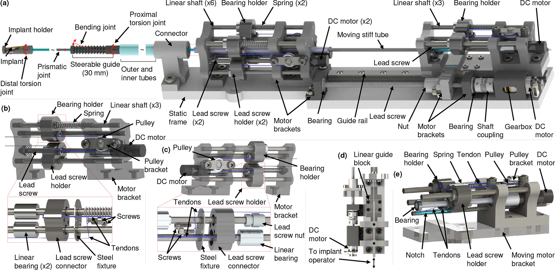
Schematic of compact actuation system. (a) CAS with the robotic transcatheter, (b) proximal torsion joint actuator and an exploded view of the bearing holder, (c) bending joint actuator and an exploded view of the lead screw holder, (d) prismatic joint actuator, and (e) distal torsion joint actuator.
Distal Torsion Joint:
The distal torsion joint (see Fig. 1(e)) orients the implant with the respect to the mitral valve leaflet and is also driven by two antagonistic PE tendons. The distal torsion joint consists of concentric top (implant holder) and bottom modules with the same mechanism as the proximal torsion joint (radius and height ). Unlike the proximal torsion tendons, routed through the inner tube of the robot, the distal torsion tendons are routed through the corresponding notches cutting on the quadlumen tube and two long Nitinol tubes (see Fig. 1(d)). The quadlumen tube is attached to the bottom module of the distal torsion joint. By controlling the required tendon pull, , and release lengths, , the distal torsion joint can achieve an angle of [−75°,75°], which also exceeds the clinical requirement. Additionally, the implant and joint manipulation PE tendons (see Fig. 1(a)) are actuated by the CAS (see Sec. II-B).
B. Compact Actuation System
The proposed CAS (268 mm (length) × 48 mm (width) × 45 mm (height)) consists of proximal torsion, bending, prismatic, and distal torsion joint actuators (see Fig. 2). The robotic transcatheter is actuated in 3D space by these actuators. The torsion and bending joints are actuated by two antagonistic PE tendons, each of which (PE tendon) have one end attached to a bearing holder (see Fig. 2(b)) or lead screw holder (see Fig. 2(c)) and the other end is attached to the corresponding joint of the robotic transcatheter (see Fig. 1). The bearing holder (see Fig. 2(b)) consists of six parts: a 3D-printed lead screw connector (Projet 5600, 3D Systems, South Carolina), two screws (M2 × 8 mm), a steel fixture, and two linear bearings (OD 9.53 mm and ID 3.18 mm). The steel fixture (304 stainless steel sheet, thickness 0.4 mm), micromachined using a femtosecond laser (Optec Laser S.A., Frameries, Belgium), is used to increase the stiffness of the bearing holder where the PE tendons are fastened using screws. The lead screw holder (see Fig. 2(c)), similar to the bearing holder, includes a 3D-printed lead screw connector, two screws, a steel fixture, a lead screw nut, and a linear bearing. The lead screw holder, guided by a linear shaft, moves linearly along the lead screw (50 mm long with 0.5 mm pitch) when actuated by a DC motor (0.5 W, 8 mm, Maxon Precision Motors, MA) with a gearbox of gear ratio 16:1. Each torsion joint and bending joint has a bearing holder and a lead screw holder.
Proximal Torsion Joint Actuator:
A pulley structure is attached to the proximal torsion joint actuator (see Fig.2(b)) to achieve bidirectional motion. One of the antagonistic proximal torsion tendons from the robotic transcatheter is attached to the bearing holder while the other tendon is attached to the lead screw holder, actuated by a DC motor (0.5 W, 8 mm, Maxon Precision Motors, MA). The two holders mentioned above are connected to each other by a PE tendon wrapped around the pulley. Also, a passive spring constrained by a linear shaft is attached to the bearing holder to reduce slack. The proximal torsion joint actuator is mounted on the static frame by the motor bracket. By pulling one tendon and releasing the other one from the robotic transcatheter, the proximal joint can be actuated to obtain the required torsion angle, . The mapping between the torsion angle, , and the tendon pull and release lengths, and , are given in Sec. III-D.
Bending Joint Actuator:
One end of each antagonistic tendon is attached to the topmost ring of the bending joint while the other free end is attached to a bearing holder or lead screw holder (see Fig. 2(c)). The tendon passes through the steerable guide, outer and inner tubes, connector, and motor bracket. Controlling two tendon lengths, and , the robotic transcatheter can also achieve the required bending angle, . The mapping between the bending angle, , and the required tendon pull and release lengths, and , are provided in Sec. III-D.
Prismatic Joint Actuator:
The prismatic joint actuator (see Figs. 2(a) and 2(d)) is used to advance the prismatic joint by translating the quadlumen tube, which is housed inside the moving stiff tube. Two notches are cut at diametrically opposite sides of the stiff tube (see Figs. 1(a) and 2(e)) using the femtosecond laser, and the same length of notch is cut from the quadlumen tube using a utility knife. This is done to route the distal torsion tendons to the distal torsion joint actuator. Both tubes are fixed with respect to each other and the moving motor bracket. The moving motor bracket, mounted on the linear guide block (LWL7-B, IKO, GA) and lead screw nut (thread size 3.18 mm), moves along the linear guide rail (LWL7-B, IKO, GA) and lead screw (thread size 3.18 mm). The DC gearmotor (HPCB 6V dual-shaft, gear ratio 100:1, Pololu Corp., NV) actuates the lead screw through a flexible shaft coupling (OD 9.53 mm and ID 3.18 mm × 1.59 mm), thereby advancing the prismatic joint. The implant tendons (see Figs.1(a) and 2(d)) are free to actuate by an operator. The prismatic joint can be actuated to 70 mm, but we restrict the motion to 60 mm for this application which is the clinical requirement. In our prior work [30], the prismatic joint was manually actuated. In this paper, the prismatic joint is advanced by the proposed linear actuation mechanism such that we can control the motion of all joints automatically.
Distal Torsion Joint Actuator:
The distal torsion joint actuator (see Fig. 2(e)), attached to the moving motor bracket, has the same pulley structure as that of the proximal joint actuator. By pulling one distal torsion tendon, , and releasing the other distal torsion tendon, , the distal joint can be actuated to obtain the required torsion angle, . In addition, compared to our prior work in [30], this paper proposed a pulley-based transmission system to actuate the torsion and bending joints by using only one DC motor per joint coupled with an antagonistic passive spring. This design reduces the dimension of the actuator by employing a precision miniature gearmotor. The miniature gearmotor also minimizes the backlash in the actuator. Also, as the tendons are attached to the bearing holder and the lead screw holder, this design can prevent the tendons from derailing (a potential problem with the pulley used in [30]). The single-use catheter (see Fig. 1(a)) can be disconnected or replaced by removing: 1) six tendons from the corresponding bearing holders and lead screw holders (see Figs. 2(b), 2(c), and 2(e)), 2) the connector from the static frame (see Fig. 2(a)), and 3) the moving stiff tube. The single-use catheter will be disposed and multi-use CAS can be draped to avoid contamination in addition to sterilizing.
III. Modeling
A. Forward Kinematics
We develop the forward kinematics model to map the joint space coordinates to the Cartesian space position and orientation of the end-effector. The robot has four joints: proximal torsion , bending (modeled as a revolute-prismatic-revolute (RPR) joint [30]: ,,), prismatic , and distal torsion joints. The coordinate frames , attached to the robot (see Fig. 3(a)), are defined as follows:
Proximal torsion angle, , rotation about ;
Bending revolute-1, , rotation about ;
Bending prismatic, , translation along ;
Bending revolute-2, , rotation about ;
Prismatic, , translation about ;
Distal torsion angle, , rotation about ;
is attached to the tip of the robot.
The link lengths of the robot are also shown in Fig. 3(a), and we assume that the bending joint bends with a constant curvature as shown in Figs. 1(c) and 3(c). Also, and . Using the product of exponentials (POE) formula [35], we derive the forward kinematics as follows: First, the transformation from the tool frame, , to the base frame, , at is given by:
| (1) |
where, the joint parameters are defined as .
Fig. 3:
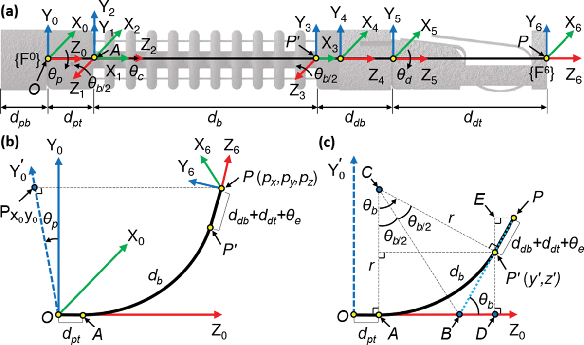
Coordinate frames assignment and geometric projections of the robot. (a) Coordinate frames assignment, (b) three-dimensional (3D) view, and (c) view.
The twists, derived in [30], are given by:
| (2) |
Finally, the forward kinematics is found to be:
| (3) |
| (4) |
| (5) |
where and represent the orientation and position of with respect to the base frame , respectively. Here, , and . Also, , and .
B. Inverse Kinematics
Given the tip position with respect to the base frame (see Fig. 3(b)), the proximal torsion joint angle can be determined by rotating the point about the axis by and projecting onto plane (the projected point is and determines a new axis ):
| (6) |
This equation produces results in the feasible range . Considering the kinematic constraints of the proximal torsion joint (see Sec. II-A), Eq. (6) is modified as:
| (7) |
where .
The angle shown in Fig. 3(c) can be calculated from the arc formed by the continuum section (bending joint) and tip point . Analyzing the projection plane (see Fig. 3(c)) gives the following results: when , we get ; when , we can infer the following geometric relationships (see Fig. 3(c)):
| (8) |
| (9) |
| (10) |
| (11) |
where point is the center of arc and . Point is the intersection of two tangents and of the arc . The radius of arc is . Point is the projection of onto the axis. Eq. (11) is obtained by applying the Pythagoras theorem to (see Fig.3(c)). Substituting (8), (9), and (10) into (11), we get:
| (12) |
We observe that (12) is a nonlinear equation in . Given , and , we use a nonlinear solver, fsolve (MAT-LAB 2021a, The Mathworks Inc., Natick, MA), to solve (12) to find the solution of , namely, . Considering the bidirectional bending configuration of the robot, the bending angle is given by:
| (13) |
Eq. (13), together with the condition when , results in a feasible range of in .
Once is obtained, we can find the prismatic joint variable, , by applying the Pythagoras theorem to (see Fig. 3(c)), where point denotes the intersection of the projection line of onto the axis and the projection line of onto the axis, and the geometric parameters (see Fig. 3(c)) are computed as:
| (14) |
| (15) |
| (16) |
Then is given by:
| (17) |
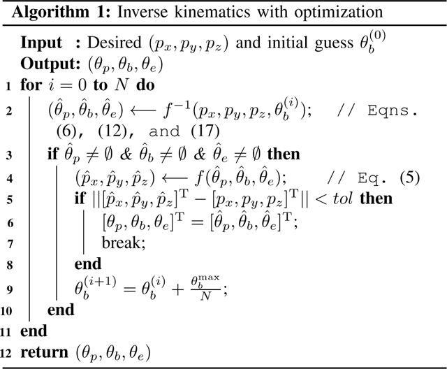
We observed that the initial guess has a significant effect to solve (12) because the nonlinear solver may result in multiple solutions and some of them may be undesirable. Hence, we propose a new algorithm (see algorithm 1) that can effectively find the optimal solution for the inverse kinematics.
For the algorithm, the tip position and an initial guess are the inputs and the joint variables are the outputs. Given the desired end tip position and an initial guess for the nonlinear solver, fsolve, we calculate the joint variables using (6), (12), and (17) as shown in Step 2. If all the joint variables are not equal to zero (Step 3), the resultant tip position is calculated using the joint variables found in Step 2 (forward kinematics). Next and are compared to see if the euclidean norm of their difference is less than a set tolereance, tol. If this condition is satisfied the calculated joint variables are an acceptable output or else the initial guess is iterated on till the condition is true.
To verify the proposed algorithm 1, we use the 3D lemniscate of Gerono (18) as a desired trajectory and compare it with the actual trajectory (recording in Step 6).
| (18) |
where . We also use the algorithm in [36], i.e., using the previous solution as the initial guess (executing Steps 2 and 9, in which Step 9 is replaced with ), to compare their performance. The parameters are as follows: initial guess degree, , and . We observe (see Fig. 4(a)) that the algorithm in [36] (red dash-dot lines) can track the desired trajectory (green lines) in the first 1/4 cycle but deviates from the desired trajectory afterwards. The proposed algorithm 1 (red dash-dot lines, see Fig.4(b)) can successfully track the whole desired trajectory (green lines). Furthermore, we use a more complicated trajectory below to verify the proposed algorithm 1:
| (19) |
where . All the parameters and setup are the same as those used in (18). We observe (see Fig. 4(c)) that the algorithm in [36] (red dash-dot lines) deviates from the desired trajectory (green lines). However, the proposed algorithm 1 (red dash-dot lines, see Fig. 4(d)) can still successfully track the whole desired trajectory (green lines).
Fig. 4:
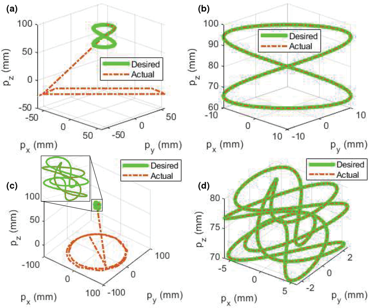
Comparison of different algorithms for inverse kinematics. (a) Algorithm in [36], (b) algorithm 1, (c) algorithm in [36], and (d) algorithm 1.
C. Singularity Analysis
Since the robot has four DoFs, here the task space variable and joint space coordinates are defined as and , respectively. The manipulator Jacobian matrix of the end effector with respect to the base frame is thus given by:
| (20) |
The joint space velocities can then be obtained by:
| (21) |
where and denote the task space and joint velocities, respectively. Since is a square matrix , we can find the analytical solution for (21) when is not singular. But when , i.e., is singular, using the L’Hôpital’s rule, we get:
| (22) |
Hence, .
In singular configuration, we propose a practical method (especially suitable for numerical computation) which can be implemented as follows:
- Step 1: For , we can approximate and . Eq. (20) is thus simplified as:
(23) - Step 2: Using the Levenberg-Marquardt method (damped least squares) [37], we can obtain the joint velocities:
where and are the damping factor and identity matrix, respectively. is the threshold value.(24)
When , we can use (21) to determine .
To evaluate the proposed approach for small values of , we consider the following example using MATLAB 2021a. The desired task space variables, and , are given by:
| (25) |
where , and . Substituting these values into the corresponding equations ((6)–(24)) we can find the joint coordinates, , and velocities, . Taking the phase portrait of the bending joint as an example (see Fig. 5), we observe that (21) provides accurate solutions when and (24) can successfully result in solutions when . In practice, one can choose a small values of which is subject to . In Sec. IV, we will use (21) and (24) for controller design.
Fig. 5:
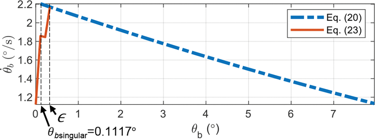
Singularity analysis for the bending joint.
D. Joint Hysteresis Compensation
The bending and torsion joints are actuated by controlling the lengths of two tendons so that they can achieve desired angles (see Sec. II). However, we observed that the accuracy is affected by joint hysteresis, which is hypothesized to be as a result of backlash in the gears and joints, assembly errors, and coupling of torsion and bending joints. Also, the tendons in torsion joints may take an undesired path due to friction between the top module and the PE tendons. To compensate for joint hysteresis, we derive the joint model as follows:
Bending Joint Hysteresis and Compensation:
Given the bending joint angle, , the required tendon pull and release lengths, and (Fig. 1(d)), can be theoretically computed as [30]:
| (26) |
| (27) |
where , and are joint parameters (see Fig. 1(d)). Since , the number of rings, is equal to 10, is close to zero in the feasible region . Therefore we can approximate and . Hence, Eqns. (26) and (27) can be simplified as a general linear equation:
| (28) |
where is the slope of the linear equation, and are experimentally determined though calibration. For each side (see Fig. 6(a)), we observe that two segments of (28) (dotted red lines in Fig. 6(a)) is a good fit for the experimental data (green lines), where the coefficients (see Fig.6(a)) are obtained by applying the least square linear regression method to the data.
Fig. 6:
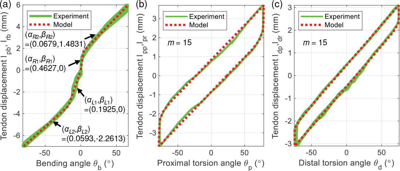
Validation of joint hysteresis compensation model. (a) Bending joint, (b) proximal torsion joint, and (c) distal torsion joint.
Torsion Joint Hysteresis and Compensation:
The hysteresis behavior of torsion joints is modeled by summing elementary Prandtl-Ishlinskii (PI) backlash operators, i.e.,
| (29) |
where and represent the input (torsion joint angle or ) and output (tendon displacement or of torsion joints, respectively (see Figs. 1(b) and 1(e)). , and are vectors of weighting value, threshold, and initial output. are inverse PI model parameters [38], [39]. where the operator and initial condition is given by:
| (30) |
| (31) |
where , and denotes the initial output. The parameters identification procedure can be found in [38], [39]. In Figs. 6(b) and 6(c), we observe that the hysteresis model for the torsion joints (dotted red lines in Fig. 6) has a good fit for the experimental data (green lines). However, we also observe some minor deviation of the experimental data (green lines, see Fig. 6) from the model (dotted red lines in Fig. 6), which affects the position accuracy of the robot tip. In Sec. IV, we will use a control technique to improve the position accuracy.
Furthermore, the PI hysteresis model for torsion joints was validated in [30]. In this paper, we extend this model by using inverse PI model parameters, and , as shown in (29). The modified generalized asymmetric Bouc-Wen model [40] could have been used but it approximates an asymmetric backlash hysteresis model and the parameter identification procedure is more complicated.
IV. Controller Design
Control techniques are essential to accurately guide the robot inside the heart to treat mitral regurgitation. There are some candidate control strategies such as model predictive control [41] and adaptive fuzzy controller [42] that can achieve this goal; however, in this paper, we are interested in developing a less complicated yet effective controller. The proposed control law, u, (see Fig. 7) is designed as:
| (32) |
where , and are nonnegative gains ( nonnegative diagonal matrices). The error vector between the reference and measurement (Cartesian position and orientation of the end-effector) is defined as denotes the error of task space velocity. and are errors of joint space coordinates and velocities. Given the reference , the nominal input , obtained using , provides feed-forward action for the robot. represents the procedure when (6), (12), (17), and algorithm 1 are used. The joint hysteresis compensation model, , is obtained in Sec. III-D ((28)–(31)). The matrix is obtained using (21) and (24), where is equal to in (21). Furthermore, the observer, a series arrangement of a median filter and a 3rd sliding mode filter, is proposed to estimate the state signals from an external tracking system. Generally, fluoroscopy or transesophageal echocardiographic guidance [43] is used as an external tracking system. In this work, we employ an electromagnetic (EM) tracker (Aurora, Northern Digital Inc., Waterloo, Ontario, Canada), which can minimize the need to use intraoperative fluoroscopy to continuously track robot positions (see Fig. 7). In the control strategy given in Fig. 7, to follow a reference trajectory and , the controller (32) minimizes the tracking errors over time by adjusting .
Fig. 7:
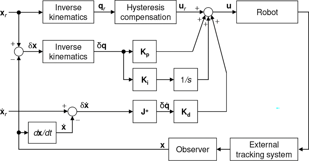
Task space control block diagram.
V. Experiment
A. Task Space Control Validation
We attached a 6-DoF EM tracker to the implant holder (see Fig. 8(a)) to gather the robot tip position and orientation, , with respect to the base frame (see Figs. 3(a) and 8(b)) to evaluate the control performance. Then, a general time-varying trajectory, according to the clinical application, i.e., beginning with a movement to the desired Cartesian point and followed by a rotation of the implant (distal joint) using setup time, , is given by:
| (33) |
where and . For , we obtain:
| (34) |
| (35) |
where and , obtained from the EM tracker, are the quaternions of the robot’s tip at time and , respectively. After sufficient tuning, the parameters in (24) and (32) are set as , , and . The experimental results are shown in Fig. 8, where is equal to 300 s and s. In Fig. 8(b), we depict the robot states (following the trajectory in (33)) at an interval of from (initial state) to 45 s, and to , where the controller is used, namely control ON. The results (see Fig. 8(c) and Table I) show that without using the controller, namely control OFF, the RMSE values in the , and directions and orientatison are as follows: , and . However, with control ON a significantly higher position accuracy is achieved ( and ), indicating the effectiveness of the proposed controller. In Fig. 8(b), the robot’s maximum bending angle is 36.45°. We did similar experiments for larger bending angles: 60°, 90°, and 120° (see Fig. 9), by setting final positions as, ,, and , respectively. The above experiments also had small RMSEs of , and , respectively. From Figs. 6(b), 6(c), 8(c), and 9(b), we observed that the clinical requirements for the proximal torsion, bending, and distal torsion angles of , and , respectively, were achieved. In Fig. 8(b), the maximum length of the prismatic joint is about (at ). However, based on the prismatic joint design discussed in Sec. II-A and the prismatic joint actuation mentioned in Sec. II-B, the prismatic joint can be actuated up to . From Fig. 8(b) and Fig. 9, we also observed that the prismatic joint is flexible enough to adapt to different bending angles and stiff enough to ensure minor deflection during prismatic joint motion.
Fig. 8:
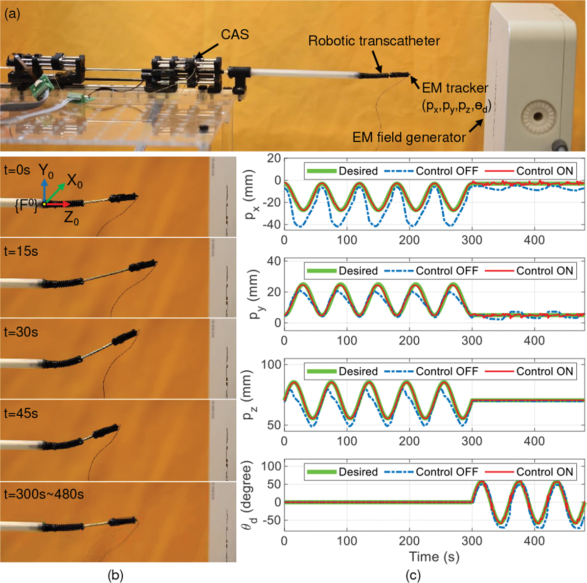
Trajectory tracking with task space control. (a) Experimental setup, (b) robot states at 15 s intervals from to (control ON) and to , and (c) comparison between control OFF and control ON for tracking the end point and the orientation of the implant holder .
TABLE I:
RMSE values by using control ON and control OFF modes in free space.
| Method | X (mm) | Y (mm) | Z (mm) | 3D (mm) | |
|---|---|---|---|---|---|
| Control OFF | 9.72 | 2.90 | 5.56 | 11.57 | 10.51 |
| Control ON | 0.73 | 0.65 | 0.22 | 1.00 | 2.00 |
Fig. 9:

Large bending angle validation with control ON for: (a) 60° bend, (b) 90° bend, and (c) 120° bend.
B. Demonstration in an Ex Vivo Porcine Heart
In this experiment, the robotic transcatheter is introduced into the left atrium of a porcine heart (LAMPIRE Biological Laboratories, Pipersville, PA) and is manipulated to reach and get under the mitral valve leaflet. The experimental setup is shown in Fig. 10(a), where the left atrium is kept dilated by attaching it to a reservoir of water at a relative height of . The water is drained out periodically through a puncture in left ventricle (at the apex of the heart) to get a clear view of the robotic transcather at all times. The aortic opening is closed using a cloth tied around it. A PTFE graft is sutured to a manually made transseptal puncture (TSP) in the inter-atrial wall of the heart and the robotic transcatheter is introduced through this graft into the left atrium. An endoscope (NIDAGE, Shenzhen, China) is introduced using another PTFE graft through a manually made opening in the left atrial wall to view the robotic transcatheter’s movement.
Fig. 10:
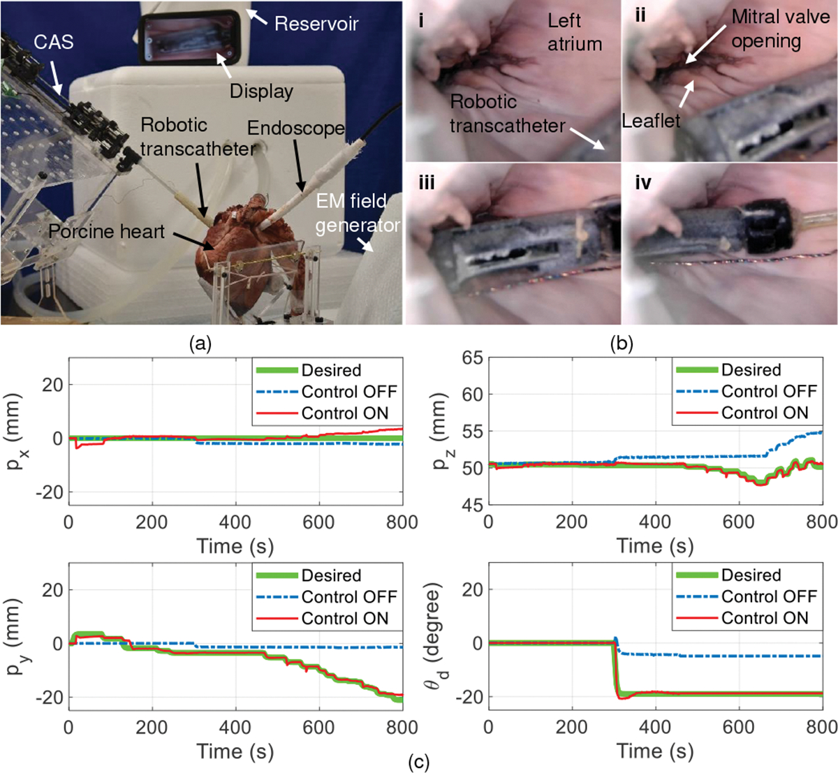
Demonstration of robotic transcatheter system in an ex vivo porcine heart. (a) Ex vivo experimental setup, (b) robot states: i) The robot is manually guided into the left atrium (control OFF), ii) the robot is advanced to be close to the mitral valve opening (control ON), iii) the robot’s tip is at the mitral valve opening (control ON), and iv) the robot’s tip is under the mitral valve leaflet (control ON), and (c) comparison between control ON and control OFF for tracking the end point and the orientation of the implant holder .
Fig. 10(b) shows the steps (i) - (iv) followed to validate the feasibility of the proposed robotic transcatheter to de-liver the mitral valve implant when control ON mode is applied. In Table II, compared to the control OFF mode (, and ), the control ON mode has a significantly higher position accuracy (, and . The interaction (friction and collision) between the robotic transcatheter and heart tissue can significantly effect position accuracy. To reduce this interaction, it is important to make a TSP posterior and slightly superior. This is an optimal puncture site as it provides a favorable working height in the left atrium. Also, the aorta was held vertically up to stop the left atrium from collapsing inwards and hence decreasing its interaction with the robotic transcatheter. Moreover, as the position and orientation of the robot’s tip are controlled separately, a slight change in orientation was observed sometimes when the robot’s tip position changed. This is possibly due to reduction of tendon friction within the robot or the friction between the robot and the heart tissue. We plan to address these challenges using force control strategies in our future work.
TABLE II:
RMSE values by using control ON and control OFF modes in the ex vivo porcine heart.
| Method | X (mm) | Y (mm) | Z (mm) | 3D (mm) | |
|---|---|---|---|---|---|
| Control OFF | 1.59 | 7.88 | 2.00 | 8.29 | 11.30 |
| Control ON | 1.43 | 0.67 | 0.21 | 1.59 | 0.59 |
C. Demonstration in a Phantom Heart through a Tortuous Path
In this experiment, we subject the robotic transcatheter to a 90° bend, to introduce tortuosity, using a 3D-printed outer sheath and then maneuver the robotic end tip within a phantom heart, as shown in Fig. 11. The 90° bend is the only tortuosity the robotic transcatheter gets subjected to while being introduced from the femoral vein into the left atrium through a steerable outer sheath (used in the clinical application). In Fig. 11(a), the robotic transcatheter is introduced into the left atrium of the phantom heart through the outer sheath. The aim of this experiment is to maneuver the robot’s end tip to reach under the mitral valve leaflet. However, we observe that the robot’s end tip cannot reach the mitral valve opening in the control OFF mode. But, when the control ON mode is applied, the robot’s end tip successfully gets under the leaflet (see Fig. 11(b)). Consequently, the control ON mode also achieves a significantly higher position tracking accuracy (see Fig. 11(c), , and compared to the control OFF mode (, and ).
Fig. 11:
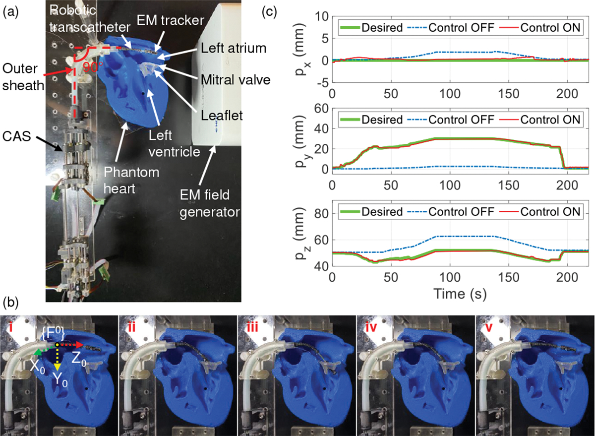
Demonstrating the maneuverability of the robotic transcatheter system in a phantom heart through an outer sheath with a 90° bend. (a) Experimental setup, (b) robot states (control ON): i) The robotic transcatheter is manually guided into the left atrium, ii) the robot’s end tip is at the mitral valve opening, iii) the end tip is under the leaflet, iv) the end tip is retracted back to the mitral valve opening, and v) the end tip returns to the home configuration, and (c) comparison between control OFF and control ON modes for tracking the end tip position.
VI. Conclusions and Future Work
This paper proposes a highly steerable and flexible catheter robot to navigate inside the heart to treat mitral regurgitation. The compact actuation system can actuate the torsion, bending, and prismatic joints bidirectionally, and joint motion exceeds clinical requirement. A pulley structure was employed to actuate the torsion and bending joints using one motor per joint and an antagonistic passive spring. The robotic transcatheter was also optimized to increase its stability and reduce bending deflection. These design improvements ensure a robust performance of the overall robotic system compared to our prior generation mitral valve delivery system designs. We proposed a new inverse kinematics model (with an optimization algorithm) and joint hysteresis and compensation model. The proposed singularity analysis method can successfully result in solutions when the Jacobian matrix is singular. These models were evaluated using case studies. To achieve task space control, we also developed a less complicated yet effective controller. A 3D trajectory tracking experiment was conducted to evaluate the effectiveness of the controller to demonstrate its feasibility. We observed that with control ON mode, a significantly higher position accuracy was achieved, indicating the effectiveness of the proposed controller. Also, using the robotic system in an ex vivo porcine heart and a phantom heart through a tortuous path were demonstrated. Compared to the control OFF mode, the control ON mode had a significantly higher position accuracy and the robot’s tip can be successfully advanced under the mitral valve leaflet. In our future work we will use ultrasound imaging, since the tracking volume with EM tracking is limited, and employ a force sensing system as feedback to evaluate the control performance of the robot in a porcine heart.
Acknowledgments
This work was supported in part by the National Heart, Lung, And Blood Institute of the National Institutes of Health under Award Number R01HL140325. The content is solely the responsibility of the authors and does not necessarily represent the official views of the National Institutes of Health.
References
- [1].Wu S, Chai A et al. , “Incidence and treatment of severe primary mitral regurgitation in contemporary clinical practice,” Cardiovascular Radiation Medicine, vol. 19, no. 8, pp. 960–963, 2018. [DOI] [PubMed] [Google Scholar]
- [2].Nishimura RA, Vahanian A et al. , “Mitral valve disease—current management and future challenges,” The Lancet, vol. 387, no. 10025, pp. 1324–1334, 2016. [DOI] [PubMed] [Google Scholar]
- [3].Mirabel M, Iung B et al. , “What are the characteristics of patients with severe, symptomatic, mitral regurgitation who are denied surgery?” European Heart Journal, vol. 28, no. 11, pp. 1358–1365, 2007. [DOI] [PubMed] [Google Scholar]
- [4].Goldstone AB, Atluri P et al. , “Minimally invasive approach provides at least equivalent results for surgical correction of mitral regurgitation: a propensity-matched comparison,” Journal of Thoracic and Cardiovascular Surgery, vol. 145, no. 3, pp. 748–756, 2013. [DOI] [PMC free article] [PubMed] [Google Scholar]
- [5].Meier S, Seeburger J, and Borger MA, “Advances in mitral valve surgery,” Current Treatment Options in Cardiovascular Medicine, vol. 20, 2018. [DOI] [PubMed] [Google Scholar]
- [6].Van Praet KM, Stamm C et al. , “Minimally invasive surgical mitral valve repair: State of the art review,” Interventional Cardiology Review, vol. 13, no. 1, pp. 14–19, 2018. [DOI] [PMC free article] [PubMed] [Google Scholar]
- [7].Nishimura RA, Otto CM et al. , “2017 AHA/ACC focused update of the 2014 aha/acc guideline for the management of patients with valvular heart disease: A report of the american college of cardiology/american heart association task force on clinical practice guidelines,” Circulation, vol. 135, no. 25, pp. e1159–e1195, 2017. [DOI] [PubMed] [Google Scholar]
- [8].Yandrapalli S, Biswas M, and Kaplan J, “Mitral valve minimally invasive surgical treatment,” In: StatPearls; [Internet], 2021. [Google Scholar]
- [9].Daon E, “Mitral Valve Repair and Replacement Options Improve Symptoms, Delay Heart Failure and Reduce Mortality,” Dec. 20 2019, [Accessed: August 5, 2022]. [Online]. Available: https://www.kansashealthsystem.com/news-room/blog/2019/12/mitral-valve-repair-replacement
- [10].Braunberger E, Deloche A et al. , “Very long-term results (more than 20 years) of valve repair with carpentier’s techniques in nonrheumatic mitral valve insufficiency,” Circulation, vol. 104, no. Suppl 1, pp. I–8–I–11, 2001. [PubMed] [Google Scholar]
- [11].Gogbashian A, Sepic J et al. , “Operative and long-term survival of elderly is significantly improved by mitral valve repair,” American Heart Journal, vol. 151, no. 6, pp. 1325–1333, 2006. [DOI] [PubMed] [Google Scholar]
- [12].De Backer O, Wong I et al. , “Transcatheter mitral valve repair: an overview of current and future devices,” Open Heart, vol. 8, no. 1, 2021. [DOI] [PMC free article] [PubMed] [Google Scholar]
- [13].Chen M and Sun L, “What is the next generation of transcatheter mitral valve repair devices?” Frontiers in Cardiovascular Medicine, vol. 8, 2021. [DOI] [PMC free article] [PubMed] [Google Scholar]
- [14].Corpataux N, Winkel M et al. , “The pascal device–early experience with a leaflet approximation device: What are the benefits/limitations compared with the mitraclip?” Current Cardiology Reports, vol. 22, pp. 74:1–74:7, 2020. [DOI] [PubMed] [Google Scholar]
- [15].Stone GW, Lindenfeld J et al. , “Transcatheter mitral-valve repair in patients with heart failure,” New England Journal of Medicine, vol. 379, no. 24, pp. 2307–2318, 2018. [DOI] [PubMed] [Google Scholar]
- [16].Abbott Laboratories. (2013) MitraClip® Clip Delivery System. [Accessed: August 5, 2022]. [Online]. Available: https://www.accessdata.fda.gov/cdrh_docs/pdf10/P100009c.pdf.
- [17].Lanfranco AR, Castellanos AE et al. , “Robotic surgery: a current perspective,” Annals of Surgery, vol. 239, no. 1, pp. 14–21, Jan 2004. [DOI] [PMC free article] [PubMed] [Google Scholar]
- [18].M R and KP S, “Robotic-Assisted Percutaneous Coronary Intervention: Rationale, Implementation, Case Selection and Limitations of Current Technology,” Journal of Clinical Medicine, vol. 7, no. 3, Jan 2018. [DOI] [PMC free article] [PubMed] [Google Scholar]
- [19].Godzik J, Mastorakos GM et al. , “Surgeon and staff radiation exposure in minimally invasive spinal surgery: prospective series using a personal dosimeter,” Journal of Neurosurgery: Spine, Feb 2020. [DOI] [PubMed] [Google Scholar]
- [20].DH A and A A, “Pitfalls and limitations in measuring and interpreting the outcomes of mitral valve repair,” Journal of Cardiothoracic Surgery, vol. 131, no. 3, Mar 2006. [DOI] [PubMed] [Google Scholar]
- [21].Kato T, King F et al. , “Robotized catheter with enhanced distal targeting for peripheral pulmonary biopsy,” IEEE/ASME Transactions on Mechatronics, vol. 26, no. 5, pp. 2451–2461, 2021. [Google Scholar]
- [22].Hu X, Chen A et al. , “Steerable catheters for minimally invasive surgery: a review and future directions,” Computer Assisted Surgery, vol. 23, no. 1, pp. 21–41, 2018. [DOI] [PubMed] [Google Scholar]
- [23].Vrooijink GJ, Ellenbroek TTM et al. , “A preliminary study on using a robotically-actuated delivery sheath (rads) for transapical aortic valve implantation,” in 2014 IEEE International Conference on Robotics and Automation (ICRA), 2014, pp. 4380–4386. [Google Scholar]
- [24].Loschak PM, Degirmenci A et al. , “Automatically steering cardiac catheters in vivo with respiratory motion compensation,” The International Journal of Robotics Research, vol. 39, no. 5, pp. 586–597, 2020. [DOI] [PMC free article] [PubMed] [Google Scholar]
- [25].Ott L, Nageotte F et al. , “Robotic assistance to flexible endoscopy by physiological-motion tracking,” IEEE Transactions on Robotics, vol. 27, no. 2, pp. 346–359, 2011. [Google Scholar]
- [26].Zhao L, Giannarou S et al. , “SCEM+: Real-time robust simultaneous catheter and environment modeling for endovascular navigation,” IEEE Robotics and Automation Letters, vol. 1, no. 2, pp. 961–968, 2016. [Google Scholar]
- [27].Shi C, Luo X et al. , “Three-dimensional intravascular reconstruction techniques based on intravascular ultrasound: A technical review,” IEEE Journal of Biomedical and Health Informatics, vol. 22, no. 3, pp. 806–817, 2018. [DOI] [PubMed] [Google Scholar]
- [28].Nayar N, Jeong S, and Desai JP, “Towards the development of a robotic transcatheter delivery system for mitral valve implant,” in Proc. International Conference on Intelligent Robots and Systems, 2020, pp. 3172–3177. [Google Scholar]
- [29].Nayar N, Jeong S, and Desai JP, “Design and control of 5-dof robotically steerable catheter for the delivery of the mitral valve implant,” in Proc. International Conference on Robotics and Automation, 2021, pp. 12268–12274. [Google Scholar]
- [30].Nayar NU, Qi R, and Desai JP, “Toward the design and development of a robotic transcatheter delivery system for mitral valve implant,” IEEE Transactions on Medical Robotics and Bionics, pp. 1–12, 2022. [DOI] [PMC free article] [PubMed] [Google Scholar]
- [31].Nayar NU, Qi R, and Desai JP, “Modeling of a robotic transcatheter delivery system,” in Proc. International Conference on Robotics and Automation, 2023, pp. 4675–4681. [Google Scholar]
- [32].Qi R, Nayar NU, and Desai JP, “Telerobotic transcatheter delivery system for mitral valve implant,” IEEE Robotics and Automation Letters, vol. 8, no. 6, pp. 3629–3636, 2023. [DOI] [PMC free article] [PubMed] [Google Scholar]
- [33].Melchiorri C and Kaneko M, Robot Hands. Berlin, Heidelberg: Springer Berlin Heidelberg, 2008, pp. 345–360. [Google Scholar]
- [34].Zhou W, Guo S et al. , “Kinetics analysis and ADRC-based controller for a string-driven vascular intervention surgical robotic system,” Micromachines, vol. 13, no. 5, 2022. [DOI] [PMC free article] [PubMed] [Google Scholar]
- [35].Murray RM, Li Z, and Sastry SS, A Mathematical Introduction to Robotic Manipulation. CRC press, 1994. [Google Scholar]
- [36].Donev A, “Numerical Methods I: Solving Nonlinear Equations,” Oct. 2014, [Accessed: August 5, 2022]. [Online]. Available: https://cims.nyu.edu/~donev/Teaching/NMI-Fall2014/Lectures.html [Google Scholar]
- [37].Chiaverini S, Siciliano B, and Egeland O, “Review of the damped least-squares inverse kinematics with experiments on an industrial robot manipulator,” IEEE Transactions on Control Systems Technology, vol. 2, no. 2, pp. 123–134, 1994. [Google Scholar]
- [38].Xu Q and Tan KK, Feedforward Control Based on Inverse Hysteresis Models. Cham, Switzerland: Springer, 2016, pp. 23–55. [Google Scholar]
- [39].Zhang J, Iyer K et al. , “Modeling and inverse compensation of hysteresis in supercoiled polymer artificial muscles,” IEEE Robotics and Automation Letters, vol. 2, no. 2, pp. 773–780, 2017. [Google Scholar]
- [40].Do T, Tjahjowidodo T et al. , “Hysteresis modeling and position control of tendon-sheath mechanism in flexible endoscopic systems,” Mechatronics, vol. 24, no. 1, pp. 12–22, 2014. [Google Scholar]
- [41].Qi R, Rushton M et al. , “Decoupled modeling and model predictive control of a hybrid cable-driven robot (hcdr),” Robotics and Autonomous Systems, vol. 118, pp. 1–12, 2019. [Google Scholar]
- [42].Kong L, He W et al. , “Adaptive fuzzy control for coordinated multiple robots with constraint using impedance learning,” IEEE Transactions on Cybernetics, vol. 49, no. 8, pp. 3052–3063, 2019. [DOI] [PubMed] [Google Scholar]
- [43].Ramlawi B and Gammie JS, “Mitral valve surgery: Current minimally invasive and transcatheter options,” Methodist DeBakey Cardiovascular Journal, vol. 12, no. 1, pp. 20–26, 2016. [DOI] [PMC free article] [PubMed] [Google Scholar]


